Article

A Demountable Connection for Low-Rise Precast Concrete Structures with DfD for Construction Sustainability-A Preliminary Test under Cyclic Loads

1
Key Laboratory of Deep Underground Science and Engineering (Ministry of Education), College of Architecture and Environment, Sichuan University, Chengdu 610065, China
2
Department of Architecture, Faculty of Engineering, Fukuoka University, Fukuoka 814-0180, Japan
3
Univ Lyon, Ecole Nationale d’Ingénieurs de Saint-Etienne (ENISE), Laboratoire de Tribologie et de Dynamique des Systèmes (LTDS), UMR 5513, 58 Rue Jean Parot, 42023 Saint-Etienne Cedex 2, France
4
School of Civil Engineering, Architecture & Environment, Xihua University, Chengdu 610039, China
*
Author to whom correspondence should be addressed.
Sustainability 2019, 11(13), 3696; https://doi.org/10.3390/su11133696
Submission received: 11 May 2019 / Revised: 3 July 2019 / Accepted: 3 July 2019 / Published: 5 July 2019

Abstract

:
As a demountable structure, the structure with design for deconstruction (DfD) is considered as a key contribution on the promotion of current construction sustainability by directly reusing valuable components from old structures. As a preliminary study, this paper investigated the cyclic behavior of bolted joints consisting of three reinforced concrete blocks bolted by steel bolts under axial compressive, focusing on the damage and failure modes, resistance mechanism and stiffness development of the joints. Results showed that the number of steel bolts, the tightening process of the bolts and concrete compressive strength all had a significant effect on the overall performance and capacity of the joints. The failure mode of most of tested joints was considered as fracture of stirrups and steel bolts in the tested joints. According to the investigation of this study, several recommendations on the design of the joints were provided.

1. Introduction

Precast concrete (PcaC) structures play a significant role on modern construction industries, which can be simply divided into three types for building structures, i.e., PcaC wall-based structures, PcaC frame structures and PcaC frame-wall combined structures [1,2,3,4]. Regardless of which type, however, the key technology of the PcaC structures is the connection between components, usually including the connections of column-wall, beam-wall, column-beam, wall-floor, etc. To be specified, the overall performance of the connections, energy-consuming capacity and economic performance play a leading role for the PcaC structures. Generally, according to previous research, there were two connection methods applied widely for the joints, wet joints and dry joints.
Wet-joint is a connection method using re-casting concrete or grouting on the site by working together with steel bars at the edge of the members, while dry connection is the method of welding or bolting at the joints. For the wet joints, there may be less secondary concrete placement on site during assembling. The overall performance of the wet joints is good and can be regarded as equivalent to that of the cast-in-place connections, but the joint construction may be complicated and the quality is not easy to guarantee, as well as the cost is high. The construction of dry joints is quick and is convenient to be constructed, reduces secondary watering on the site and is easy to be maintained and reused. It can truly reflect the advantages of modern construction industrialization and development of prefabricated structures. Dry connection has certain application in Europe and other countries, but it is limited to be used in earthquake-prone zones such as Japan and China, especially for high-rise structures. The important constraint factor is that the seismic performance of the joints needs to be strengthened to meet the requirements of the structures in the zones.
On the other hand, as a demountable connection, dry connection is a key technology for the structures with design for deconstruction (DfD), which can significantly promote the construction sustainability for the reuse of the components connected by the joints, including almost all structures such as steel and reinforced concrete (RC) structures. The direct reuse of valuable components obtained from old structures is being attracted by engineers and researchers worldwide, for the process of reuse can effectively control the pollution of construction and demolition wastes well, can reduce the use amount of raw construction materials for new structures, can consume less energy for the process of the construction, which all can promote the construction sustainability. Comparing with the recycling of construction and demolition wastes, the reuse of the wastes shows its superiority, as shown in Figure 1.
According to the literature, dry connection and wet connection including seaming of fabricated members such as shear walls have been researched well in the past 50 years. In the 1980s and 1990s, Wan et al. [5,6,7,8] studied the performance of the wet joints of prefabricated slab structures, including the influence of shear span ratio, axial pressure, reinforced concrete and joint types on the joints of large-slab structures was considered. Their results have been compiled into the “Design and Construction Regulations for Prefabricated Large-Span Residential Buildings” [9] and are still in use today. In 1989, Rizkalla et al. proposed a keyway-type wet joint to connecting shear walls through for PcaC shear wall systems [10]. The wet joint form of PcaC shear walls was an early and extremely simple form. However, the overall performance of the joints was much lower than that of the cast-in-place joints in the structures, indicating that the joints should be strengthened further. After that, many researchers [11,12,13,14,15,16,17] proposed some enhancement methods to improve the joints proposed by Rizkalla et al. such as increasing steel reinforcement and steel plate. In 1996, several professors such as Khaled in Canada proposed several types of precast concrete wall joints connected by steel bars, and conducted a pseudo-static test on the precast concrete walls with steel bars [18,19,20,21]. Among the wall joints proposed, the methods connecting the upper and lower steel bars by welding and bolting reduced the secondary concrete pouring at the joints. The core ideal of the proposals can be considered as a dry connection at that time, already. After that, the research on dry connection began to appear in large numbers.
In 2008, Crisafulli and Restrepo [22] proposed a dry connection method referring to the welded joints for steel structures. The connection method is simple and convenient, however, the application to the concrete structure system needs further study. In China, the Ye team [23,24,25,26] introduced a German composite panel design and production technology, and improved the seismic design of laminated plate shear walls [24] and studied the shear behavior of the joints. In 2010, Henry et al. [27,28,29] proposed a dry joint based on using bolting and welding and then performed a series of finite element analyses and experiments of the dry joints. In Japan, the early-age main research findings of prefabricated shear walls have been published by Architecture institute of Japan, such as Ref. [30]. Takagi et al. and Nagae et al. [31,32,33] proposed a steel rebar-steel plate welding method for prefabricated shear walls. In this joint, the floor slab is placed on the lower shear wall, the root of the upper shear wall is designed with an open connected by a wielded steel plate, and then the steel bars of the upper and lower shear walls are welded on the steel plates. Finally, the opening is closed with a non-shrinking high-strength mortar. Jiang et al. [34,35,36,37,38] also carried out many studies on assembled RC shear walls, and first proposed the "inserted reserved hole grouting steel lap joint members” for the wet joints [36]. The connection method used simple and effective spiral reinforcement stirrups inside, which strengthened the ferrule effect on the concrete and enhanced the anchoring performance of the steel inside the concrete [37,38]. The research teams of Qian et al. [39,40,41] proposed a vertical steel sleeve slurry anchor connection for PcaC shear walls, a single row steel bar indirect overlap method. Its failure mode, energy consumption capacity, stiffness, etc. was proved to be basically the same as the cast-in-place structure, and can be used as a joint connection for fabricated structures [42].
In recent years, Sun et al. [43] proposed a new fully assembled RC shear wall (IPSW) structure connected by high-strength bolts. Their core idea was: the horizontal joints were welded to an inset frame, which was first placed on PcaC wall panels and the lower edge, by connecting the end of the vertical reinforcing bar ends. The adjacent walls were connected by means of connecting steel frames and high-strength bolts for transferring the forces between adjacent wall panels. Since that, more domestic studies on dry nodes started to be presented in China, but the main research direction was focused on the form and behavior of dry-type joints, and the research on the overall performance and stress analysis of dry-type nodes is limited.
In summary, the form of previous proposed wet connections is usually complex comparing with dry connection. Since the wet joint solution has the ability to be equivalent to cast-in-place, early studies on the joints have focused on wet joints. The research on the wet connection joints of fabricated concrete structure has achieved a series of considerable results, however, the joints have the following problems: (1) The wet connection method can only increase the speed of construction to a certain extent, for secondary casting processes of concrete usually is necessary; (2) the construction quality of the wet connections is not easy to guarantee [33,34,40]; (3) the wet connection is costly [35]. Compared with wet connection solutions, dry connection solutions can effectively overcome the above problems, and have the advantages of reducing pollution on the site, reducing resource waste, and simplifying the construction process. In recent years, the research trend of fabricated shear wall joints has begun to shift to dry connection. In China, a variety of fabricated shear wall structure joints based on reserved holes and sleeve grouting have been proposed. With the improvement of construction quality and the requirements of construction speed, the research of dry joints began popular. At present, the research on dry joints mainly focuses on the verification of dry connection, the research on the resistance mechanism of dry joints is limited. The main objective of the study is to investigate the structural behavior of demountable bolted joints under cyclic loads to analyze the resistance mechanism of the joints under cyclic shear loading, to study the feasibility and overall performance of the joints for the low-rise structures in earthquake-prone zones.

2. Proposal of a Prefabricated Shear Wall System with DfD for Low-Rise Buildings

The study proposed a prefabricated shear wall system with DfD for low-rise buildings in earthquake zones with low and moderate seismic intensity. The horizontal and vertical components of the buildings are connected by demountable joint zones consisting of steel bolts and steel plates. The system can be assembled fast and easily, and be deconstructed when necessary, which is easy to reuse for next service life. Figure 2 elaborates the construction and deconstruction process of the system. After or during the deconstruction phage, the valuable and reusable components or elements in the structures first will be collected, and then their various performances such as structural capacity will be evaluated and improved if necessary. The components or elements will appear in a construction site of a new structure, as new components for the structure. This process extends the lifespan of the elements and saves the raw materials needed for construction industries, which both promote the construction sustainability. The main components and their features of the prefabricated shear wall systems with DfD for low-rise buildings are summarized as:
1)
Prefabricated corner members. The members work as tie columns in frame structures, which are divided into T-shaped, L-shaped or cross-shaped members at the corners of the structures.
2)
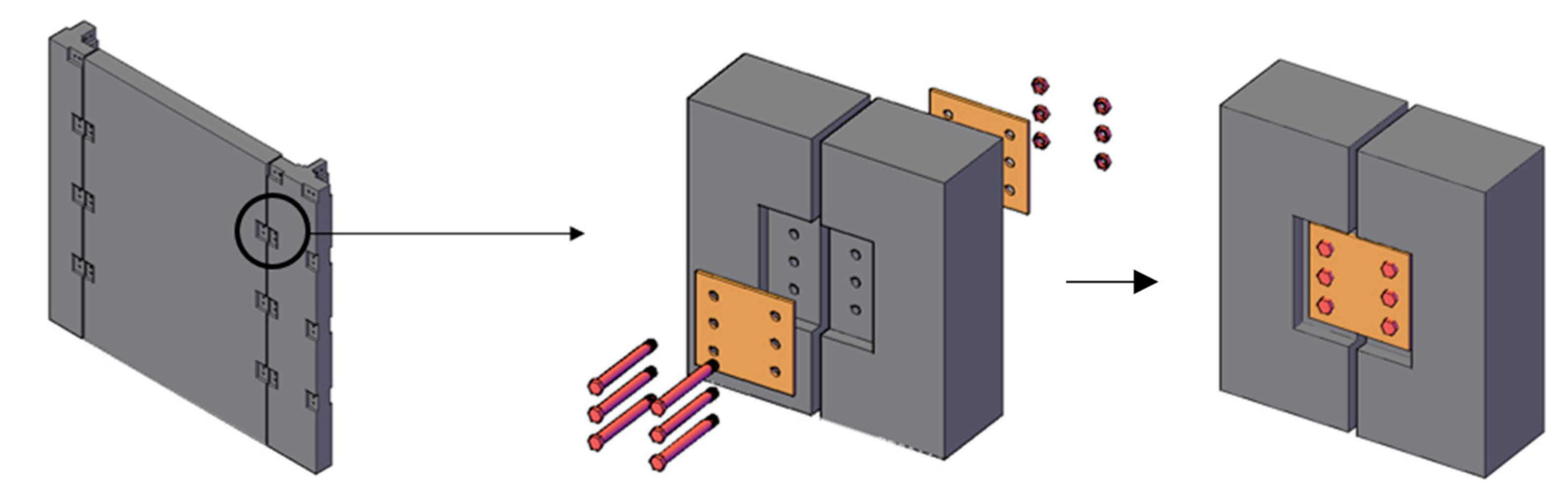
Prefabricated wall panels. The panels are connected with their surrounding members by dry nodes around the panels. The joints include horizontal and vertical type joints connected between the panels and corner members. The horizontal joints could be more complex for they are formed by connecting the lower wall panel, floor slab and the upper wall panel at the same time in some cases.
3)
Prefabricated slabs (roof panels). The elements are similar to the prefabricated wall panels described above. The four corners of the prefabricated slab are recessed inwardly to allow the prefabricated corner members to pass through. The edges of the slab are made as invisible beams to reinforce the joint zone and protrude 100 mm to overlap surrounding wall panels. Finally, the wall panel passes through the dry connection.
As shown in Figure 2, the installation and construction processes of the proposed structures are summarized as:
1)
Leveling the site and pouring foundation beams at the prefabricated corner members and the bottom surface of prefabricated wallboard, and pre-burying dry joints in the foundation beams.
2)
Positioning the prefabricated columns members. The prefabricated members are bolted to the dry joints of the foundation beams by connecting steel plates.
3)
The prefabricated wall panels are connected with the foundation beams and the prefabricated columns by bolting dry joints to make the walls and the foundation beams become a whole.
4)
PcaC floor slabs are overlapped at the reserved groove of wall panels and prefabricated column members, and the positions are determined, and then the dry connections are bolted to the wall panels to form a layer of the structures.
5)
Repeat the above steps to complete the installation of the structure.
As the key points of the systems with DfD, referring to the bolt connection method applied in steel structures, the proposed steel-bolted connection consists of steel bolts and steel plate. Firstly, the bolt holes are reserved and set in the invisible beam and column zones of the components using Polyvinyl chloride (PVC) pipes. After aligning the components according to the holes, the components are connected by the bolts and steel plates, as shown in Figure 3.

3. Experimental Investigation

This section studied the connection method proposed through experimentally investigating the vertical bolted joints consisting of three reinforced concrete blocks, demountable steel bolts and steel plate. It should be noticed that the specimens used for the preliminary study were of small scale meaning that the effect of geometry of the specimens should be taken into account in future studies.

3.1. Details of Test Specimens

Figure 4 shows the details of the specimens. Before casting the concrete blocks, 25 mm diameter PVC pipes were used to set the positions of bolt holes. A gap of 10 mm was reserved between the concrete blocks when assembling. The steel bolts and steel plates were paved and the concrete blocks were connected by fastened bolts to form the vertical bolted joint specimens. A total of five specimens were made, whose main study parameters are listed in Table 1. The main variables include compressive strength of concrete, the number of bolts and the arrangement of bolts in the joints. The M20 steel bolts were adopted for the joints. The reinforcement and steel plate diagram of the joints are shown in Figure 4 and Table 1. In addition, the basic material properties are shown in Table 2.

3.2. Loading Method and Measurement

The loading method applied in the current study was as per “Standard for test method of concrete structures” [44] and “Specification for seismic test of buildings” [45]. The controlling of the loading of the specimens was loading-control at the first stage, and then was changed as a load-displacement controlling method after the specimens yielded. The details of the loading history are shown in Figure 5. When the bearing capacity of the specimens dropped below 85% of their corresponding maximum load or the specimen was damaged heavily, the tests were stopped. During the tests, when the strain of reinforcement, or steel plate or concrete reached their yield levels or when the specimens presented an obvious plastic deformation, the specimens were considered reaching their yield status. The observations and records of the test include mainly: (a) Damage of the specimens, including cracking, concrete crushing, etc., which all were recorded at the corresponding positions; (b) compressive load and vertical displacement and (c) stress and strain history of reinforcements, concrete and steel plates. It should be noticed that the condition of the applied hydraulic jack was abnormal at the early stage of loading during the testing of the specimen LSSZ11. In this study, therefore, the behavior of the specimen was presented as a referring.

4. Results

4.1. Damage Observation

The failure process of the bolted joint specimens LSSZ4 and LSSZ5 was basically the same, as shown in Figure 6. The deformation and damage process of the specimens was: (1) The initial test phase, the specimens remained intact. (2) When the load reached about 80 kN, the concrete crack first appeared around the right bolt #4 of the central block and developed obliquely downward. After that, the concrete around the bolts #1 and #4 presented oblique cracks. (3) After the load reached about 180 kN, the concrete around the bolts #1 and #4 was crushed and the inner reinforcements of the block were gradually exposed. At this time, the steel plate began to show signs of a rotation with the bolt #3 around the side blocks. The rotation of the steel plate caused the concrete around the bolt to be crushed under pressure, and the bolts #1, #4 and the surrounding concrete or steel bars were squeezed to cause the surrounding concretes to be crushed, the longitudinal rib and the hoop of the blocks started to yield. After that, the concrete around the bolts #2 and #3 was cracked further. After the concrete around the bolts #2 and #3 was crushed, the steel plate rotated greatly and the surrounding concrete was damaged heavily. The central block lost its restraint and the specimens were destroyed. In summary, when the specimens LSSZ4 and LSSZ5 were destroyed heavily, the concrete in the joint zone was seriously damaged. The longitudinal steel rebars inside the blocks had reached yield level. The steel plate rotated around the side bolt #3 in the side blocks, and the bolts were less damaged in the two specimens.
Figure 7 shows the damage and deformation of the specimen LSSZ11. The specimen used more stirrups in its joint zone compared to the specimens LSSZ4 and LSSZ5, but using the same number of bolts in all the three joints. The first crack was found when the loading reached about 120 kN and at below of bolt #4 and then was developed obliquely. The damage observation in the joint was basically the same as that of the above two specimens. As the loading progressed, the oblique cracks appeared in the concrete around the bolts #1 and #4 and concrete was crushed, and the steel plate also rotated around the bolt #3 as the loading progressed, as shown in Figure 7c. When the load reached about 400 kN, the bolt #1 in the left block was suddenly cut, and a large displacement was confirmed in the central block. The steel plate rotated around the bolt #3 and immediately caused the longitudinal reinforcement of the joint zone of the right block to be bent, the stirrup was then broken and the bolt #1 was pulled out. At that time, the central block lost its constraint from two side blocks, the vertical displacement was largely increased, and the test specimen was then destroyed totally (Figure 7d). The damage characteristics of specimen LSSZ11 at an early stage were basically consistent with those of the specimens LSSZ4 and LSSZ5, because all the specimens used the same number of bolts in the joints. Due to more stirrups were used in LSSZ11, the concrete cracks appeared later and the bolt shearing fracture occurred for they were subjected higher resistance from the stronger joint (Figure 7d).
The damage process of the specimens LSSZ12 and LSSZ13 was similar, as shown in Figure 8, which was summarized here taking LSSZ12 as an example, as following: The oblique cracks mainly appeared around the bolts #1 and #6 when the loading was increased to about 280 kN. The vertical displacement of the central blocks in both specimens was small at this stage. After that, the strain value of the longitudinal bars in the joints reached or exceeded their tensile yield level. From Δy to 2Δy, the concrete cracks developed around the bolts #1 and #6, and then gradually became longer and wider and began to spall off (Figure 8b,c). After the concrete around the bolts #1 and #6 began to be crushed, the concrete cracks began to appear around the bolts #2 and #5, and the steel plate began to rotate around the bolt #5. Then, the bolts #1 and #6 significantly offset from the bolt holes and were squeezed by the surrounding concrete and steel bars to cause the surrounding concrete was crushed, and the longitudinal ribs and the stirrups were deformed in the blocks. Subsequently, the stirrups around the bolts #1 and #6 fractured, and the bolt #1 in the left block was cut. After that, the test specimens can continue to resist till about 570 kN, the bolt #1 in the right block was cut, and the steel plate rotated largely. Finally, the bolt #6 was pulled away from the bolt hole and the specimen was broken totally (see Figure 8). The damage of LSSZ12 was summarized as: The concrete in the joint zone was seriously damaged, the longitudinal reinforcements inside the blocks were obviously deformed and the stirrups were fractured, the steel plate rotated around the side steel bolts (bolt #5) and the bolts in the upper corner of the two side blocks (bolt #1) also were usually cut. Compared with specimen LSSZ11, the specimens LSSZ12 and LSSZ13 have a higher bearing capacity and more ductile damage characteristics.

4.2. Load-Displacement Relationship

The load-displacement curves of the tested bolted joints are shown in Figure 9. The abnormal behavior of the LSSZ11 was caused by the abnormal condition of hydraulic jack. The characteristics of the hysteresis curves of the specimens (except for LSSZ11) are as follows: (1) The residual deformation of the specimens LSSZ4 and LSSZ5 after unloading was large, and the smooth section caused by the slippage of the bolts occurred after the load reached about 160 kN. After the peak load was reached, the load-displacement curves dropped sharply for the joints were not able to continue to resist the compressive force. (2) The deformation of the specimens LSSZ12 and LSSZ13 were less till the loading of 150 kN and was basically in their elastic phases. After that phase, the specimens shown a large plastic deformation stage where the displacement increased rapidly but the axial load raised less, indicating that large damage occurred in the joint zone led to the larger slippage of the bolts. At the same time, the area of the hysteresis loop increased meaning that the energy consumption of the specimens increased for their plastic damage. (3) The specimen LSSZ12 exhibited some sudden changes at the latter loading stage in the load-displacement curve due to the shearing fracture of several bolts around 65 mm and 85 mm, while LSSZ13 also exhibited some similar drop sections at the displacement of 23 mm, 30 mm and 78 mm. In summary, the general characteristics of the curves of the bolted joints were: The load-displacement curves were not very full and the specimens owned a good ductility to absorb deformation energy. However, the large slippage of the steel bolts was observed in all the bolted joints.

4.3. Skeleton Curves

The skeleton curves of the bolted joints are shown in Figure 10. The overall characteristics of the skeleton curves are summarized as: (1) When the specimens LSSZ4 and LSSZ5 reached their peak loads, the curves both dropped rapidly indicating that the specimens quickly lost their bearing capacity. For this, the damages of the two specimens were considered as a brittle plastic damage. (2) The skeleton curve of the specimen LSSZ11 was basically the same as those of the specimens LSSZ4 and LSSZ5, except for its peak loading capacity. (3) Due to the increase of the number of steel bolts, the specimens LSSZ12 and LSSZ13 presented the significantly higher peak load than other specimens. A longer and smoother slippage stage appeared after all the specimens reached their yield status. Additionally, a staggered arrangement of the bolts in the joint LSSZ13 did not effectively enhance the loading capacity of the bolted joints, which was attributed to that the side bolts of the joint made the steel plates rotate largely. This is also because the side three bolts in the same line can make the joint more effective to resisting the loading before the concrete was crushed heavily near one of the corner bolts. The heavy damage of the corner bolt hole can destroy the balance of the three bolts more easily. Comparing with the welded joints [46], the stiffness corresponding to the maximum load of the bolted joints was much smaller, which can be attributed to the slippage of bolts caused by damage of concrete and deformation of steel bolts. However, the bolted joints showed a larger deformation capacity under such cyclic axial compressive loads.

4.4. Stiffness Degradation

The stiffness degradation curves of the joint specimens are shown in Figure 11. Here, the stiffness of joints represented the secant stiffness of maximum load of each cycle. It was found that the stiffness degradation of all the bolted joints could simply be divided into three phases: The rising phase, rapid falling phase and slow-degradation phase. The first one usually was caused by the slight slippage of the bolts at the early stage of the loading, while the rapid degradation phase generally started from the damage of concrete or deformation of steel bolts in the joints and ended at the yield status of the joints, where the slow degradation phase started till the end of the tests. Through the comparison of the stiffness degradation curves of the steel welded joint specimens [46], the stiffness degradation of the bolted specimens was sharper than those of the welded specimens, and the diacritical points between the second and third phase is more obvious, as shown in Figure 11. At the latter phase of the loading, the welded joints presented the larger stiffness than those of the bolted joints.

5. Discussions on Failure and Recommendations for Design of the Joints

5.1. Deformation and Resistance Mechanism of Joints

About the resistance and deformation mechanism of the bolted joints, several key features are summarized in the following sections. Here, in the name of the same specimens/blocks, “1” and “2” represent that the measured strain values at the upper and below parts of the specimens/blocks. For example, LSZ1-1 and LSZ1-2 of LSSZ4 in Figure 12 mean the strain values of longitudinal rebars located at the upper and below positions of the rebars in LSZ1 block of LSSZ4.
Resistance of steel reinforcements in the concrete block—at the initial stage of loading, the strain of the reinforcing rebars was small, and increased sharply after the displacement of central block reached 5–10 mm where the concrete started to crack. After the vertical displacement reached 15 mm, the strain of the rebars of the joint zone reached their yield levels and the deformation of the rebars developed till the final fracture of steel bars. Besides, when the concretes of the joints have stronger compressive strength, the contribution of reinforcing rebars in the blocks became lower, as specimen LSSZ13 shown in Figure 12.
Concrete deformation—according to the analyses, the deformation of concrete blocks was concentrated in the joint zone of the tested specimens, and the main damages of concrete are summarized orderly as: Concrete cracking occurred near the bolt holes, crack rapid development and heavy destroy of concrete and concrete spalling finally. As shown in Figure 13, the test data of the concrete strain proved above the analysis results, in which concrete strain increased as the displacement up to its peak strain. In addition, the strain development of the foot part of concrete blocks was presented as follows: The concrete strain increased slightly with applied loading, but the concrete strain of the parts was quite small and was between 50–400 με when the specimen was damaged. This indicates that the damage of the concrete block was local for the bolted joints in RC wall structures. Additionally, the strain of steel bars in the joint zone was much larger than those of other steel bars, which indicates that the steel rebars in the joint zone were severely damaged by the tensile stress but the reinforcements away from the joint zone was small. Figure 12 shows the development of strain of steel reinforcements in concrete blocks in two representative joints.
Deformation of the steel plate—similar to concrete deformation in the joints, the strain of the steel plate in two directions both increased as the vertical displacement of the joints. However, the increasing state was found in the early stage of loading except for the specimen LSSZ13. At the latter stage of the loading, as shown in Figure 14, except for that the main strain of steel plate of LSSZ13 exceeded the yield strain of the plate, the main strain of the steel plates of other specimens was much smaller than the yield strain of the plates, indicating that the bolts of the LSSZ13 worked more effectively to resist the deformation during the whole loading process. The reason can be explained as the arrangement of steel bars, which made the steel plate contribute more resistant at the latter stage of loading. From this point, we can understand that the steel plate should be improved for the enhancement of cyclic behavior of the bolted joints, not only by increasing the number of the steel bolts and providing a reasonable arrangement of steel bolts.

5.2. Main Features of the Load-Displacement Response of the Bolted Joints

As shown in Figure 15, the bolted joints may have a considerable loading capacity comparing with the welded joints with the same conditions, however, the slippage of the bolted joints should be noticed during the design of the joints. As a summary, the load-displacement response of the joints can be divided into five possible stages, as follows:
• Stage I—Elastic deformation stage.
In this stage, a well-tightened joint can make the bolted concrete blocks work well without large slippage and work elastically without large residual deformation after removing the loading. It should be noticed that the key process of the stage is the tightening of the bolts, which can be well controlled by current technologies. The mechanical properties of the steel bolts and steel plate also are very important influencing factors for the stage, such as using of high strength bolts is helpful to this stage.
• Stage II—Elastic-low plastic deformation stage.
The plastic deformation of the joint is caused by the small damage of bolted joints such as concrete cracking, which usually is started from the hole for plastic deformation resistance capacity of concrete usually is much smaller than other parts in the joints. The small bending deformation of the steel bolts also is one reason for the plastic behavior of the joints. Therefore, at this stage, the plastic deformation of the joints significantly depends upon the mechanical properties of concrete used and steel bolts. This stage usually is the end until the joint reaches its yield status.
• Stage III—Large plastic and slippage stage.
The slippage stage of the joints is a process of stiffness rapid degradation and a large number of plastic damages of the joint zone, mainly including the concrete crushing damage in holes in the blocks and the large bending deformation of steel bars. During this stage, the loading resistance of the joints still can keep increasing, however, the increase ratio of loading usually is low. This stage is usually ended at a feature point at where the joints start to enter a load hardening stage, which may be for the expansion deformation of the joint zone such as the possible expansion of two steel plate caused by crushed concrete.
• Stage IV—Hardening stage.
The hardening stage of the joints may be caused by following reasons: The steel bolts reached a re-tightening status caused by expansion of inside concrete; or the bolts contact with the inside stirrups; or the movement or slippage of steel plate is restrained by surrounding parts of the joints. This stage makes the joints rapidly develop the loading capacity to reach their maximum load resistance status.
• Stage V—Loading degradation stage.
After reaching the maximum loading of the joints, the loading capacity of the bolted joints usually starts to decrease because of the following reasons: (1) The shearing fracture of stirrups contacted with steel bolts, (2) shearing fracture of steel bolts, (3) put-out of the steel bolts and (4) cracking or fracture of the steel plate. Among them, the first two cases may usually happen when few stirrups are used or the used stirrups are too weak, or the steel bolts are too weak. The case (4) may occur when only a small number of steel bolts are used for the joints and the steel plate is too weak or too thin. When an out-plan load occurs in the joint face possibly caused by the out-plane deformation of the steel plate led by inside damaged concrete, case (3) can appear.

5.3. Possible Failure Modes of the Bolted Joints

According to this study, the possible failure modes of the steel bolted joints proposed for a RC structure with DfD have:
(1) Concrete crushing and stirrup shearing fracture.
The strong steel bolts develop the damage of concrete, especially when concrete is weak, and then the bolts contact directly surrounding stirrups. The coming loading makes the shearing fracture of steel stirrups happen.
(2) Shearing fracture of steel bolts.
When low-strength steel bolts are used or over high strength concrete and a steel plate are used for the joints, the failure mode might happen.
(3) Tensile fracture of steel bolts.
This mode usually is caused by the out-plane damage of concrete between steel plates, and it gets worse when a weak steel bolt is used.
(4) Put-out of steel bolts.
The over-damage of the concrete and steel plate ma the bolts under high tensile stress with their nuts together, which then widens the holes in the steel plate and concrete block. This failure mode usually occurs with a fracture of the bolts at their screwing zone.
(5) Fracture of the steel plate.
When enough steel bolts and a relative weak steel plate are used in the bolted joints, this mode possibly occurs because of the direct strong shear behavior of the bolts.

5.4. Recommendations for Design of Bolted Joints in a RC Structure with DfD

Based on this study, the following recommendations for the design of the steel bolted joints are provided here for improving the safety and sustainability of the RC structures with DfD:
A)
Improve the plastic deformation of concrete holes by using high strength concrete, or using a metal pipe inside the hole to increase the bolt-hole interface strength.
B)
Arrange a reinforcement enhancing zone to restrain the whole move/slippage of the bolts to help the stirrups to resist the movement of steel bolts.
C)
High strength bolts are recommended for the joints.
D)
Tightening of the steel bolts is a necessary and key process to controlling the slippage.
E)
Prevent the out-plane deformation of joint is also a key factor to avoid the put-out of steel bolts and the tensile fracture of steel bolts. Therefore, a demountable connection set consisting of two steel plates pre-connected with concrete blocks is recommended for the joints, which is being investigated in our next studies.

6. Conclusions

This paper proposed a simply demountable bolted vertical connection for low-rise buildings in earthquake-prone zones. As a preliminary study, this paper investigated the cyclic behavior of the demountable connection consisting of steel bolts and a steel plate, which could hopefully promote the current construction industrialization and sustainability. This promotion is reached by direct reusing of the components from old structures. However, it should be mentioned that this paper preliminarily studied as the number of the specimens was very limited and more studies are expected in the future. The main conclusions are drawn as follows:
  • The study verified that the rotation and slippage of the bolts was a very key factor for the steel-bolted joints. When the concrete was crushed heavily or the holes were destroyed, the large rotation of steel plate could occur.
  • A staggered arrangement of the bolts could not improve the load carrying capacity of the joints, which could be explained with the fact that the side bolts of the joints made the steel plate rotate largely at a large deformation stage.
  • As the possible failure modes of the steel bolted joints, according the preliminary study, the put-out of steel bolts and fracture of the steel plate also could occur, which complemented the well-understood failure mode of the joints described in the existing literature, such as concrete crushing and stirrup shearing fracture.
  • The paper provided several recommendations to improve the structural behavior of the joints based on investigation and analyses, such as using a demountable connection set consisting of two steel plates pre-connected with concrete blocks.

7. Patents

The invention patent based on the above content, “Low-layer assembled composite wall house bolt connection node structure” was authorized on 2016 [47] (Patent number: 201410171848.0).

Author Contributions

Conceptualization, G.C. and F. X.; Data curation, G.C., F.X. and Y.X.; Formal analysis, G.C., F.X., YX.; Funding acquisition, F.X.; Investigation, G.C., F.X., Y.X. and Y.L.; Methodology, G.C., F.X. and Y.X.; Project administration, F.X.; Resources, G. C. and F.X.; Software, G.C. and F. X.; Supervision, G.C. and F.X.; Validation, G.C., F.X. and Y.X.; Visualization, G.C. and F. X.; Writing – original draft, G.C., F.X. and Y.X.; Writing – review & editing, G.C., F.X., Y.X., A.S.L. and M.Y.

Funding

This research was funded by the National Key R&D Program of China, grant No. 2018YFD1100903-02. The APC was funded by the same funding, No. 2018YFD1100903-02.

Conflicts of Interest

The authors declare no conflict of interest.

References

  1. Elliott Kim, S. Precast Concrete Structures; CRC Press: Boca Raton, FL, USA, 2016. [Google Scholar]
  2. Aaleti, S.; Sritharan, S. A simplified analysis method for characterizing unbonded post-tensioned precast wall systems. Eng. Struct. 2009, 31, 2966–2975. [Google Scholar] [CrossRef]
  3. Perez, F.J.; Pessiki, S.; Sause, R. Experimental Lateral Load Response of Unbonded Post-Tensioned Precast Concrete Walls. ACI Struct. J. 2013, 110, 1045–1056. [Google Scholar]
  4. Frosch, R.J.; Li, W.; Jirsa, J.O.; Kreger, M.E. Retrofit of non-ductile moment-resisting frames using precast infill wall panels. Earthq. Spectra 1996, 12, 741–760. [Google Scholar] [CrossRef]
  5. Wan, M.; Zeng, B. Design and Calculation of Joints in Assembly Plate Structures. Build. Struct. 1984, 1, 43–50. (In Chinese) [Google Scholar]
  6. Wan, M.; Zeng, B. Strength and Stiffness of Joints in Large Plate Structures. J. Build. Struct. 1986, 4, 54–69. (In Chinese) [Google Scholar]
  7. Wan, M. Design of Joints for Large Plate Structures. Build. Sci. 1987, 2, 50–61. (In Chinese) [Google Scholar]
  8. Wan, M. Explanation on Some Problems in “Code for Design and Construction of Assembled Slab Residential Buildings”. Build. Sci. 1990, 4, 57–60. (In Chinese) [Google Scholar]
  9. Ministry of Housing and Urban-Rural Development of China (MHURD). JGJ1-1991, Specification for Design and Construction of Fabricated Board Civil Building Structures; MHURD: Beijing, China, 1991.
  10. Rizkalla, S.H.; Serrette, R.L.; Heuvel, J.S.; Attiogbe, E.K. Multiple Shear Key Connections for Precast Shear Wall Panels. PCI J. 1989, 104–120. [Google Scholar] [CrossRef]
  11. Foerster, H.R.; Rizkalla, S.H.; Heuvel, J.S. Behavior and design of shear connections for loadbearing wall panels. PCI J. 1989, 34, 102–119. [Google Scholar] [CrossRef]
  12. Nakaki, S.D.; Englekirk, R.E. PRESSS Industry Seismic Workshops: Concept Development. PCI J. 1991, 36, 54–61. [Google Scholar] [CrossRef]
  13. Priestley, M.J.N. Overview of PRESSS Research Program. PCI J. 1991, 36, 50–57. [Google Scholar] [CrossRef]
  14. Stanton, J.F.; Hawkins, N.M.; Hicks, T.R. PRESSS Project 1.3: Connection classification and evaluation. PCI J. 1991, 36, 62–71. [Google Scholar] [CrossRef]
  15. Priestley, M.J.N. The PRESSS Program: Current Status and Proposed Plans for Phase III. PCI J. 1996, 41, 22–40. [Google Scholar] [CrossRef]
  16. Priestley, M.J.N.; Sritharan, S.; Conley, J.R.; Pampanin, S. Preliminary Results and Conclusions from the PRESSS Five-Story Precast Concrete Test Buildings. PCI J. 1999, 44, 42–67. [Google Scholar] [CrossRef]
  17. Han, J.; Li, Z.; Song, X. A New Type of Connection for assembling concrete frame: Study on Prestressed. Assem. Fram. Struct. Constr. Ind. Constr. 2009, 39, 100–103. (In Chinese) [Google Scholar]
  18. Soudki, K.A.; Rizkalla, S.H.; Daikiw, R.W. Horizontal connections for precast concrete shear walls subjected to cyclic deformations. II: Prestressed connections. PCI J. 1995, 40, 82–96. [Google Scholar] [CrossRef]
  19. Soudki, K.A.; West, J.S.; Rizkalla, S.H.; Blackett, B. Horizontal connections for precast concrete shear wall panels under cyclic shear loading. PCI J. 1996, 41, 64–80. [Google Scholar] [CrossRef]
  20. Soudki, K.A.; Rizkalla, S.H.; LeBlanc, B. Horizontal connections for precast concrete shear walls subjected to cyclic deformations part 1: Mild steel connections. PCI J. 1995, 40, 78–96. [Google Scholar] [CrossRef]
  21. Park, R. A perspective on the seismic design of precast concrete structures in New Zealand. PCI J. 1995, 40, 40–60. [Google Scholar] [CrossRef]
  22. Crisafulli, F.J.; Restrepo, J.I. Ductile steel connections for seismic resistant precast buildings. J. Earthq. Eng. 2003, 7, 541–553. [Google Scholar] [CrossRef]
  23. Lian, X.; Ye, X.; Wang, D.; Jiang, Q.; Chang, L. Experimental Analysis of Seismic Behavior of Superimposed Slab Shear Walls. J. Hefei Univ. Technol. (Nat. Sci.) 2009, 32, 1219–1223. [Google Scholar]
  24. Lian, X.; Ye, X.; Jiang, Q.; Wang, D. A New Green Resident Structure System: The Superimposed Slab Shear Walls System. Ind. Constr. 2010, 40, 79–92. (In Chinese) [Google Scholar]
  25. Ren, J.; Ye, X. Seismic Behavior Research on the Superimposed Slab Shear Walls for Different Axial-Load Ratios. Struct. Eng. 2010, 26, 66–71. (In Chinese) [Google Scholar]
  26. Jiang, Q.; Ye, X.; Zhong, X. Calculation Model for Superimposed Slab Shear Walls. China Civ. Eng. J. 2012, 45, 8–12. (In Chinese) [Google Scholar]
  27. Henry, R.S.; Aaleti, S.; Sritharan, S.; Ingham, J.M. Concept and finite-element modeling of new steel shear connectors for self-centering wall systems. J. Eng. Mech. 2009, 136, 220–229. [Google Scholar] [CrossRef]
  28. Bournas, D.A.; Negro, P.; Molina, F.J. Pseudodynamic tests on a full-scale 3-storey precast concrete building: Behavior of the mechanical connections and floor diaphragms. Eng. Struct. 2013, 57, 609–627. [Google Scholar] [CrossRef]
  29. Negro, P.; Bournas, D.A.; Molina, F.J. Pseudodynamic tests on a full-scale 3-storey precast concrete building: Global response. Eng. Struct. 2013, 57, 594–608. [Google Scholar] [CrossRef]
  30. Architecture Institute of Japan (AIJ). Evaluation Method and Design of Shear Strength for Multi-Story Precast Reinforced Concrete Structural Walls; AIJ: Tokyo, Japan, 2002; p. 116. (In Japanese) [Google Scholar]
  31. Takagi, J.; Shimonishikida, S.; Kitayama, K.; Minami, S. Development of static analysis models of existing wall-type precast reinforced concrete residential buildings. J. Struct. Constr. Eng. (Trans. AIJ) 2012, 77, 113–120. (In Japanese) [Google Scholar] [CrossRef]
  32. Nagae, T.; Tahara, K.; Fukuyama, K.; Matsumori, T.; Shiohara, H.; Kabeyasawa, T.; Kono, S.; Nishiyama, M.; Nishiyama, I. Seismic performance assessment and improvement of prestressed concrete building based on E-defense shaking table test. J. Struct. Constr. Eng. (Trans. AIJ) 2012, 77, 75–84. (In Japanese) [Google Scholar] [CrossRef]
  33. Shiohara, H.; Imai, H.; Nishiyama, M. Recent Developments of Structural Regulations for Precast Concrete Buildings. Concr. J. 2003, 41, 3–9. (In Japanese) [Google Scholar] [CrossRef]
  34. Jiang, H. Research and Application of Prefabricated Concrete Shear Wall Structure Technology. Housing Ind. 2011, 6, 33–36. (In Chinese) [Google Scholar]
  35. Yang, Y. Experimental Research on Seismic Performance of Precast Shear Wall with Vertical Joint Surface. Master Thesis, Harbin Institute of Technology, Heilongjiang Sheng, China, 2011. (In Chinese). [Google Scholar]
  36. Liu, W.; Jiang, H.; Geng, Y.; Yan, H. Plug-In Type Preformed Hole Grouting Reinforcement Lapping Connection Component. Chinese Patent ZL200820090150.6, 8 April 2009. (In Chinese with English abstract). [Google Scholar]
  37. Jiang, H.; Zhang, H.; Liu, W.; Yan, H. Experimental Study on Plug-in Filling Hole for Steel Bar Anchorage of the PC Structure. J. Harbin Inst. Technol. 2011, 43, 28–36. (In Chinese) [Google Scholar]
  38. Jiang, H.; Chen, Z.; Zhang, J.; Wu, B.; Tian, Y.; Liu, W. Quasi-static test of precast reinforced concrete shear wall structure. J. Build. Struct. 2011, 32, 34–39. (In Chinese) [Google Scholar]
  39. Zhang, J. Experimental Research on Seismic Behavior of Full-scale Precast Shear Wall Substructure. Master Thesis, Harbin Institute of Technology, Heilongjiang Sheng, China, 2010. (In Chinese). [Google Scholar]
  40. Qian, J.; Peng, Y.; Zhang, J.; Qin, H.; Li, J.; Liu, G.; Zhao, F.; Li, L. Tests on seismic behavior of pre-cast shear walls with vertical reinforcements spliced by grout sleeves. Build. Struct. 2011, 41, 1–6. (In Chinese) [Google Scholar]
  41. Zhang, W.; Qian, J.; Chen, K.; Qin, H.; Liu, G.; Li, J. Tests on seismic behavior of precast shear walls with vertical distributed reinforcements spliced by a single row connection rebars. Build. Struct. 2011, 41, 12–16. (In Chinese) [Google Scholar]
  42. Zhang, W.; Qian, J.; Yu, J.; Qin, H.; Liu, G. Tests on seismic behavior of precast shear walls with cast-in-situ boundary elements and vertical distributed reinforcements spliced by a single row of steel bars. Chin. Civ. Eng. J. 2012, 45, 89–97. (In Chinese) [Google Scholar]
  43. Sun, J.; Qiu, H.X. Seismic behavior and mechanism analysis of innovative precast shear wall involving vertical joints. J. Cent. South Univ. 2015, 22, 1536–1547. [Google Scholar] [CrossRef]
  44. China Academy of Building Research. GB/T 50152-2012, Standard for Test Method of Concrete Structures; China Academy of Building Research: Beijing, China, 2012. (In Chinese) [Google Scholar]
  45. China Academy of Building Research. JGJ/T 101-2015, Specification for Seismic Test of Buildings; China Academy of Building Research: Beijing, China, 2010. (In Chinese) [Google Scholar]
  46. Xu, Y. Dry Connections for Precast Shear Walls in Rural Housing. Ph.D. Thesis, Sichuan University, Chengdu, China, 2017; p. 183. (In Chinese). [Google Scholar]
  47. Xiong, F.; Xu, J.; Xu, Y.; Liu, B. Lower Housing Prefabricated Composite Wall Structure of Nodes Connected. Chinese Patent ZL201410171848.0, 10 February 2016. (In Chinese with abstract). [Google Scholar]
Figure 1. Roles of reduction, recycling and reuse of wastes in construction sustainability.
Sustainability 11 03696 g001
Figure 2. Construction and deconstruction of precast concrete (PcaC) structures with design for deconstruction (DfD) for low-rise buildings.
Sustainability 11 03696 g002
Figure 3. The bolted connection for the proposed PcaC wall-based system.
Sustainability 11 03696 g003
Figure 4. Details of joint specimens.
Sustainability 11 03696 g004
Figure 5. Load history.
Sustainability 11 03696 g005
Figure 6. Damage of the bolted joint LSSZ4
Sustainability 11 03696 g006
Figure 7. Damage of specimen LSSZ11.
Sustainability 11 03696 g007
Figure 8. Damage of specimen LSSZ12.
Sustainability 11 03696 g008
Figure 9. Load-displacement relationship of tested specimens.
Sustainability 11 03696 g009
Figure 10. Skeleton curves of concrete block joint specimens.
Sustainability 11 03696 g010
Figure 11. Stiffness degradation of the bolted joints.
Sustainability 11 03696 g011
Figure 12. Development of strain of longitudinal rebars of representative specimens.
Sustainability 11 03696 g012
Figure 13. Development of strain of concrete of representative specimens.
Sustainability 11 03696 g013
Figure 14. Development of strain of the steel plate of tested specimens.
Sustainability 11 03696 g014
Figure 15. Schematic diagram of the load-deflection curve.
Sustainability 11 03696 g015
Table 1. Details of specimens.
#Size of Blocks (mm3)Stirrups (D@ Spacing)#of bolts / Line# of BoltsSteel Plate (Length × Width × Thickness; mm3)
LSSZ4, 5860 × 200 × 950D8@1504/2 Lines240 × 140 × 8
LSSZ11880 × 200 × 950D8@150 + D8@100
(joint zone)
4/2 Lines220 × 140 × 8
LSSZ12880 × 200 × 9506/3 Lines220 × 200 × 8
LSSZ13880 × 200 × 9506/3 Lines (staggered)280 × 200 × 8
Table 2. Material properties.
SpecimensConcrete MaterialsSteel Materials fy (MPa)/ fu (MPa)/εy (10-6)
fcu (MPa)Ec (MPa)εy (10-6)C8C12Q235BBolts
LSSZ424.628117262438.4/
619.1/
2192
459.3/
639.9/
2297
283.3/
399.8/
1417
320.0/
407.1/
1600
LSSZ522.723779286
LSSZ1150.434622292420.9/
595.0/
2105
447.6/
623.3/
2238
291.4/
397.5/
1457
320.0/
407.1/
1600
LSSZ1250.434622292
LSSZ1335.731525340

