Article

Seismic Performance of a New Type of Fabricated Tie-Column

1
Research Institute of Structural Engineering and Disaster Reduction, Tongji University, Shanghai 200092, China
2
State Key Laboratory of Disaster Reduction in Civil Engineering, Tongji University, Shanghai 200092, China
3
Key Laboratory of New Technology for Construction of Cities in Mountain Area, Chongqing University, Ministry of Education, Chongqing 400045, China
4
School of Civil Engineering, Chongqing University, Chongqing 400045, China
5
Chongqing Shixiao Dulong Technology Co., Ltd., Chongqing 400084, China
*
Author to whom correspondence should be addressed.
Sustainability 2018, 10(6), 1716; https://doi.org/10.3390/su10061716
Submission received: 6 May 2018 / Revised: 18 May 2018 / Accepted: 22 May 2018 / Published: 24 May 2018

Abstract

:
The reinforced concrete (RC) frames infilled with masonry walls are widely used in buildings. It has been well recognized that the arrangement of tie-columns can improve the wall integrity and seismic performance. However, the existing cast-in-situ tie-column (CSTC) has some problems, and a new type of fabricated tie-column (FTC) which can be recycled for secondary use is proposed in this study. Two specimens, the wall constrained by the cast-in-situ tie-columns (W-CSTC) and the wall constrained by the fabricated tie-columns (W-FTC), were designed and constructed. Low cyclic loading tests were carried out and some parameters, such as the failure modes, hysteretic curves and so forth, were used to evaluate the applicability of the FTC. The results show the W-FTC has a certain initial stiffness and strength, favorable deformation capacity, and the FTC can not only enhance the wall integrity to meet the functional requirements of tie-columns, but also solve the connection problems and reduce the adverse effects on the frame structure.

1. Introduction

In many parts of the world, Southern Europe, Asian and Latin America, and so forth, it is a common practice to use masonry infill walls as interior or exterior partitions in reinforced concrete (RC) structures. Many experiments have been conducted and proved that the presence of infill walls significantly increases the strength, stiffness and seismic energy dissipation capacity of buildings [1,2,3,4]. Besides, experience from actual earthquakes suggests that properly constructed infill walls might inhibit the collapse of inadequately designed or insufficiently detailed structural systems [5,6]. Since they are normally considered as nonstructural elements, their presence is often ignored by designers [7], and their contribution to the structural stiffness is not fully considered in many national design codes.
However, the experience during the past earthquakes has demonstrated that masonry infill walls in RC buildings caused several undesired effects under earthquakes, such as torsional effects induced by irregular arrangement in plane, soft-story effects induced by irregularities in elevation, short-column effects due to openings, and stress concentration in frame members due to the connection with infill walls [8]. Nevertheless, experimental researches showed that soft-story effects can occur even in uniform distribution of infill walls [9,10]. These undesired effects were mainly because of the lateral stiffness provided by infill walls. Gunay and Mosalam [11] indicated that if infill walls had larger stiffness compared to the frame surrounding it, the soft/weak story mechanism might be triggered by the sudden brittle failure of the stiffer walls due to the combined effects of in-plane and out-of-plane response. In the report of 2011 Van earthquake in Turkey [12], it was stated that infill walls made structures very stiff, therefore limited the lateral drifts as long as they kept their integrity inside the confining frames. In some cases, infill walls caused sudden changes in the lateral stiffness due to out-of-plane failure
Although researches have been enriched and analytical methods have been significantly improved over the last decades [13,14,15,16,17,18], it is still difficult to precisely describe the interaction between infill walls and the main structure [19,20]. It is not only because the characterization of masonry infill is discrete, but the contacting interface between infill walls and the surrounding frame also keeps changing as time goes by. In addition, some researches indicated the influence of the joists should be accounted since the joists could have great influence [21,22,23,24]. Therefore, based on their abundant practice experience and relevant studies, different countries have distinct design provisions to deal with this problem. For example, in the current Chinese seismic design code [25,26], the period reduction factor is usually applied to increase the seismic action, and certain measures should be taken to reduce the unfavorable effect of the infill wall, such as the flexible connection between masonry infill walls and the surrounding frame [7,27,28]; however, the analytical model including infill walls is still not necessary in the analysis and design procedure. In Eurocode 8 [29], in the case of severe irregularities in plan due to the unsymmetrical arrangement of the infill walls, spatial models including infill walls are required for the structural analysis. If there are considerable irregularities in elevation, the seismic effects in the vertical elements of each story would be increased [7].
To prevent walls from undesirable failure mode, tie-columns—which are commonly used in masonry structures—are adopted when the span of walls filled in the frame is too large or there is no constraint at the ends of infill walls. In seismic design, it is generally required that the tie-column could provide appropriate constraint on the infill wall, which has a favorable deformation capacity and energy dissipation capacity thus. Currently, tie-columns are mainly cast-in-place with two methods respectively: (1) Infill walls are constructed from the first floor, while 5.0 cm gap between the tie-column and the beam is reserved when casting the tie-column, bitumastic oakum or cement mortar is then used to seal the gap after all floors are completed. (2) Infill walls are constructed from the top floor, and the steel bar of the tie-column should be anchored into the upper beam (plate), and no gap is left between the tie-column and the beam. For both methods, the steel bar of the tie-column should be anchored into the upper beam (plate). However, there are some limitations of the existing cast-in-situ tie-column (CSTC): inconvenient construction, poor construction quality, and improper connection leading to insufficient restraint on the infill wall or excessive restraint on the frame. As mentioned before, reliable flexible connection between the main structure and the tie-column, the tie-column and the infill wall should be ensured; consequently, it is important to propose a new method to solve these problems.
Moreover, with the rapid social development, the demolition and reconstruction of the infill wall are very common, and the country is calling for certain measures to recycle demolished materials and save environmental resources. Therefore, in this paper, a new type of fabricated tie-column is proposed, which is composed of fabricated tie-column modules. The modules can be removed and replaced easily for secondary use. Two specimens, the wall constrained by the cast-in-situ tie-columns (W-CSTC) and the wall constrained by the fabricated tie-columns (W-FTC), were designed and constructed respectively, the behaviors of the specimens under low cyclic loading tests were compared, such as the bearing capacity, failure mode and hysteretic curve, and so forth Finally, its applicability is also discussed.

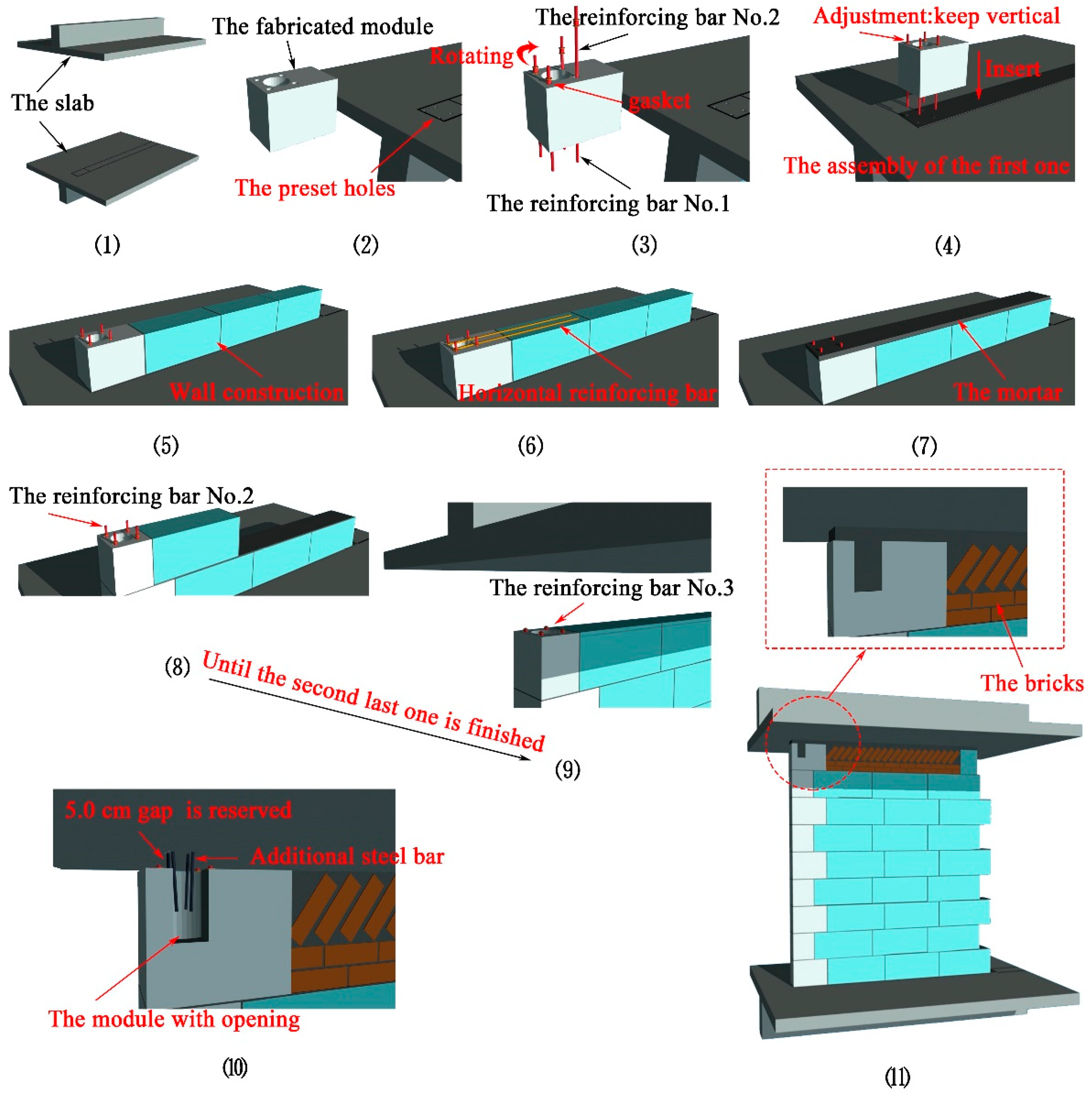
2. Fabricated Tie-Column

The new fabricated tie-column (FTC) mainly includes tie-column modules and reinforcing bars with screw threads. A larger cylindrical hole is reserved for pipeline installation in the center of the tie-column module, and four smaller cylindrical holes are also reserved around the larger one for tie-column modules connection by reinforcing bars (shown in Figure 1). Depending on the shapes, the new FTCs can be classified into different categories: standard-type, “-”-type, T-type, cross-type and L-type, which can meet various demands for different parts of the structure (shown in Figure 2).
The installation process is illustrated in Figure 3, and the disassembly process is its inverse process. The steps 1–4, which involve Figure 3(1)–3(11) in Figure 3, are introduced as follows:
  • Step1:
Figure 3(1): Determining the installation position of the wall and the tie-column. For instance, the slab is shown in this figure.
Figure 3(2): Preparation for the material (module, reinforcing bar and so forth), the preset holes and so forth
  • Step 2:
Figure 3(3): The installation detail for the reinforcing bars in the 1st module is presented. Two different types of reinforcing bars, the No. 1 and No. 2, are utilized, and the main difference of reinforcing bars is the length. The reinforcing bars are connected by the thread as shown in the figure.
Figure 3(4): Assembly of the 1st module. The holes in the slab are infilled with structural adhesive, and then the reinforcing bars No. 1 is inserted into the slab (worker can recognize the bars No. 1 as a support for bars No. 2). Worker can adjust the module to the right position, and the 1st module is fixed finally.
Figure 3(5): Wall construction.
Figure 3(6): Two horizontal reinforcing bars are applied for wall reinforcement at every 500 mm along the wall height direction, and both ends of the bars are anchored in the column.
Figure 3(7): The mortar laying for binding.
  • Step 3:
Figure 3(8): Assembly of the 2nd module. Different from the 1st module, the reinforcing bar No. 2 is only needed since the reinforcing bars in the 1st module can provide support, and the following progresses which are shown in Figure 3(5) and 3(6), such as the wall construction are omitted.
Figure 3(9): Repeating this work in the Figure 3(8) until the second last module is completed. The only difference for the second last module is the reinforcing bar No. 3, as shown in the figure. Compared with bar No. 2 (shown in Figure 3(5)), the end of the bar No. 3 is in the same level with the top of this module, which is prepared for the next step.
  • Step 4:
Figure 3(10): Assembly of the last module. The special module with opening and the reinforcing bar No. 3 are used, and 5.0 cm gap between the module and slab is reserved for bar tightening. In the opening, the additional steel bars are inserted into the roof for anchorage. As can be seen, the top of the infill wall is different, which is involved in the construction method, and the brown parts are bricks.
Figure 3(11): The 5.0 cm gap is cast with concrete later, and the completed diagram is shown in the figure.
Compared with the traditional cast-in-situ tie-column (CSTC), the proposed FTC has the advantages of convenient installation, simple and flexible construction, which greatly improves the construction efficiency and saves the construction cost. This product can retain the functions of traditional CSTC and greatly improve the aesthetics of tie-column. Furthermore, for solving the problem of column templates’ swelling and hollowing, it standardizes the “tooth” connection and improves the quality of secondary wall construction. In addition, it is also environment-friendly to use this product. Before removing the infill wall, workers can rotate the screw bar to the removable position, and the FTC can be divided into tie-column modules, hence the dismantled modules can be reused in somewhere else, which can save resources and costs, and increase economic benefits.

3. Experimental Program

3.1. Test Specimens

There are three kinds of failure modes of masonry wall: shear friction failure, diagonal compression failure and shear compression failure. The masonry wall with larger lateral force and smaller vertical force, tends to have shear friction failure; the masonry wall with larger vertical pressure and smaller lateral force, tends to have diagonal compression failure; for the masonry wall with appropriate proportion between the lateral force and vertical force, shear compression failure occurs. Post-earthquake data indicate that diagonal cracks are more common, which is also the characteristic of shear compression failure. Therefore, the shear compression failure mode, which is related to the aspect ratio and the ratio of compressive stress to shear stress in the cross section, is mainly investigated in this paper.
Two specimens, the wall constrained by the cast-in-situ tie-columns (W-CSTC) and the wall constrained by the fabricated tie-columns (W-FTC), were designed to investigate the seismic behavior of the fabricated tie-column (FTC), and the low-cyclic loading tests were carried out later. Some seismic performance parameters, such as the bearing capacity, failure mode, hysteretic curve, energy dissipative capacity, stiffness degradation, and so forth, were compared and analyzed to verify the applicability of the proposed new fabricated tie-column.
The configurations of specimens are shown in Figure 4. To prevent the specimens from sliding, the base beam was grooved with a depth of 20 mm, the visible height in Figure 4 is then 1480 mm, and 1480 mm plus 20 mm equals to 1500 mm. Both specimens were 1500 mm in height, 3000 mm in width and 190 mm in thickness. The cross-section of the tie-columns and the beams were a rectangle with the dimension of 200 × 200 mm, and 240 × 200 mm, respectively.
The masonry wall was made of clay bricks and cement mortar. The mean compressive strength of mortar, obtained by testing mortar prisms, was 7.05 MPa (with coefficient of variation (COV) = 8.65%). The concrete had average compressive strengths of 26.93 MPa (COV = 6.09%) for the tie-beam and tie-column. The compressive bearing capacity of two tie-column modules was measured, and the average value was 1016.67 kN (COV = 3.96%). For the specimen W-CSTC, the longitudinal reinforcement of the tie columns and beams consisted of 4 steel bars with 10 mm diameter and yield strength (fy) being 300 MPa, two horizontal reinforcing bars (fy = 300 MPa) with the diameter of 6 mm were applied for wall reinforcement at every 500 mm. For the other specimen, the only difference was that reinforcing bars shown in Figure 1b were applied to replace the whole longitudinal steel bar.

3.2. Test Setup

The testing system consists of reaction wall, loading equipment, sensors and data acquisition system. The test setup is illustrated in Figure 5. The specimen was tested under combined constant vertical load and reversed cyclic lateral load, simulating seismic effects scenario. At first, the vertical load was exerted on the upper beam by means of two hydraulic jacks and maintained to be 180 kN during the test. The lateral load was applied to specimens at the upper beam level. Prior to the cracking load, the lateral load was controlled by the force. After cracking, the lateral load was applied by displacement control mode. During load control stage, for accurately capturing the cracking load, the load for the first cycle was 40 kN and the following increment was 20 kN per each cycle. During displacement control stage, the initial displacement increment was 0.5 mm per each cycle, and it was increased to 1.0 mm later during the load decline stage. Each stage of loading consisted of only one fully reversed cycle to the selected amplitude level. The lateral loading protocol is illustrated in Figure 6. Each fully reversed load cycle was completed in one minute. Testing was stopped when the lateral load was reduced to 85% of the ultimate load.
The specimen was instrumented with two linear variable differential transformers (LVDTs), one for loading control and the other for displacement recording. One end of the LVDTs were connected to the specimen, and the other were connected to the base beam to eliminate the influence of relative displacement [30,31,32,33]. The average shear displacement of the infill wall was measured by diagonally placed dial gauges. During the whole test process, the force was recorded by the loading equipment. Arrangement of instruments is shown in Figure 5. Since specimens had been painted white, optical observation was used to record the cracks in specimens and all significant damage process that occurred during the tests (such as crack development in masonry and tie-columns).

4. Experimental Results and Analysis

4.1. Loading Process and Damage Behavior

Damage conditions at failure for specimens are shown in Figure 7. Both specimens were shear compression failure, and the specimens mainly experienced three stages: (a) elastic stage; (b) nonlinear stage; (c) bearing capacity decline stage. However, there are some differences.
For the wall constrained by the cast-in-situ tie-columns (W-CSTC), when the load increased to 200 kN, discontinuous horizontal and vertical micro-cracks initiated in the middle of the wall and extended to the upper and lower-left corner. With the lateral force increased to 240 kN, these cracks propagated and widened, and the significant cross-diagonal cracks emerged. Meanwhile, horizontal micro-cracks appeared at the upper part of tie-columns. When the ultimate load was almost arrived, these discontinuous cracks gradually penetrated into the whole specimen, and several main horizontal cracks appeared obviously in tie-columns. In subsequent loading stage, the bearing capacity decreased, but the deformation of the wall increased rapidly, companied with full development of cracks. In addition, many cracks appeared at the ends of the tie-beam.
For the wall constrained by the fabricated tie-columns (W-FTC), when the load increased to 120 kN, discontinuous diagonal micro-cracks initiated at the lower-right corner of the wall, and horizontal cracks appeared on the interface of tie-column modules. With the lateral force increased to 160 kN, these cracks propagated and widened, companied with the emergence of new cracks on the other diagonal direction, hence appearing a significant X-shape. Meanwhile, vertical cracks appeared on the interface between tie-columns and the wall. When the ultimate load was almost arrived, except for the features appeared in the third stage of the W-CSTC, some horizontal cracks along the horizontal reinforcing bars appeared obviously in the middle of the wall.
More cracks were distributed in the middle and lower part of the W-FTC, the cracks would not extend to the tie-beam, which could avoid unfavorable effects on the seismic performance of the beam. Thus, the damage condition of the W-FTC was more reasonable.

4.2. Hysteretic Characteristic Curve

The lateral load-displacement hysteretic curves of specimens are illustrated in Figure 8. The envelope curves of specimens are shown in Figure 9. For the infill wall, the deformation capacity and energy dissipation capacity are more important than the bearing capacity, the characteristics in three stages mentioned before are concluded as follows.
The specimens almost remained in elastic stage before cracking, the deformation and the area of hysteretic curves were considerably small. The initial stiffness of W-CSTC and W-FTC were 657.8 KN/mm and 205.9 KN/mm respectively (the former stiffness was about 3.2 times of the latter one), which indicated cast-in-situ tie-columns (CSTC) could provide a larger stiffness for the RC frame than fabricated tie-columns (FTC). For the lower stiffness with the FTC, the seismic action of the RC frame would be smaller. Lower stiffness also means lower constraint and interaction, which is beneficial for weakening the irregular arrangement and soft-story effects, especially for strong RC frame. In addition, the cracking displacements of W-CSTC and W-FTC were 0.54 mm and 1.13 mm respectively. With larger elastic deformation, the W-FTC may need no repair under minor earthquakes.
After cracking, the stiffness of W-CSTC changed little at first, it began to decrease with cracks propagation later. When the ultimate load was almost arrived, the stiffness degradation was drastic, but the displacement was still small (1.23 mm). On the other hand, the stiffness degradation of W-FTC appeared at first, the displacement under the ultimate load was 6.16 mm, and the area of the hysteretic curve increased obviously with better energy dissipation performance. Thus, the W-FTC maybe more repairable than W-CSTC under moderate earthquakes. In this situation, different types of retrofitting techniques can be utilized [34,35,36,37].
The deformation of specimens increased quickly in the bearing capacity decline stage. If the test was stopped before the lateral load was reduced to 85% of the ultimate load, the corresponding displacement of the amplitude level of the last cycle was the ultimate displacement. The results showed that the ultimate displacements of W-CSTC and W-FTC were 10.3 mm and 9.21 mm respectively, the deformation capacities were similar. However, the W-CSTC achieved a lower energy dissipation with narrower cycles, while the W-FTC was more favorable for the requirement of “no collapse under major earthquakes”, which is the most important design criterion in Chinese Seismic Design Code. For this purpose, various energy dissipation devices can also be incorporated to increase structural seismic resistance [38,39,40,41,42].

4.3. Energy Dissipation Capacity

In order to quantitatively evaluate the energy dissipation capacity of these specimens, among the numerous hysteretic cycles of each test, three typical hysteretic cycles corresponding to three critical states were chosen for further analyses. Similar to previous research [43], these critical states were defined on the basis of the observed damage propagation, being the cracking state, ultimate state, and failure state respectively. In addition, according to previous researches, the coefficient of equivalent viscous damping (CEVD) ξ and energy dissipation indicators (EDI) I E , d i s were evaluated to diagnose the energy dissipation capacity of the infill wall [43,44,45,46].
The CEVD ξ and EDI I E , d i s are calculated from experimental results using following equations:
ξ = E D 2 π E P
I E , d i s = E D E i n p
where E D is the energy dissipation per cycle, E P is the input potential energy in the same loading cycle, E i n p is the elastic input energy per cycle. The schematic diagrams are shown in Figure 10, the E D , E P and E i n p equal to the areas S A B C D , S O B E + S O D F , and S A B E + S C D F respectively. When the values of CEVD and EDI are larger, the elastic input energy has been efficiently dissipated. In addition, EDI is also an indicator for stiffness degradation according to the definition. The values of CEVD and EDI, which are presented in Table 1, can be used to evaluate the energy dissipation capacity effectively thus. In addition, the energy dissipation E D is also presented in Table 1.
The similar tendency of values of the CEVD and EDI is observed in Table 1. In the loading process, in general, these parameters of the W-FTC increased obviously, while these of the W-CSTC increased initially and then decreased. Thus, the energy dissipation capacity of the W-CSTC decreased, ranging from the ultimate load to the failure load companied with the stiffness degradation, which is also shown in Figure 8a. Therefore, although the W-CSTC had a larger deformation energy at the failure state, the performance would be unsustainable under the real earthquake scenario, since at that time, more and more energy would be input, while in this test, only one cycle was applied. On the other hand, the W-FTC exhibited superior energy dissipation performance with the increasing input energy, indicating that it would be more practical in real engineering projects which may be subjected to mega earthquakes beyond prediction.

5. Conclusions

A new type of fabricated tie-column (FTC), which is convenient for assembly and disassembly, is proposed in this paper for recycling use. The compositions, construction process and characteristics are introduced. The benefits are demonstrated, and the seismic performance of two specimens, the wall constrained by the cast-in-situ tie-columns (W-CSTC) and the wall constrained by the fabricated tie-columns (W-FTC), under low cyclic loading tests are comparatively studied and analyzed. Based on this study the following conclusions can be drawn:
(1)
The FTC can provide effective constraints for the infill wall. Although the deformation capacity of the W-FTC was similar to the W-CSTC, the initial stiffness of the W-FTC was only one third of the W-CSTC, indicating that it provides smaller stiffness and constraints for the RC frame, which is beneficial for weakening the irregular arrangement and soft-story effects, especially for strong RC frames. Compared with the W-CSTC, the W-FTC has more reasonable failure mode and cracks distribution. Additionally, no stiffness degradation is occurred when the failure load of the W-FTC is almost arrived.
(2)
The W-FTC has better energy dissipation capacity. The values of parameters, the coefficient of equivalent viscous damping (CEVD) and energy dissipation indicators (EDI), of the W-FTC are larger than the W-CSTC, which means the W-FTC could dissipate the input energy more efficient and sustainable.
In conclusion, the proposed new FTC can not only solve the connection problems and reduce the adverse effects on the frame structure, but also provide a better seismic performance for the infill wall. In addition, the assembly and disassembly processes are simple, which is also beneficial to industrial production and recycling process.

Author Contributions

Z.L. wrote the paper and directed the study. H.Z. analyzed the data and revised the paper. C.J. conceived the idea, provided valuable discussions and revised the paper. He took responsibility of the corresponding work. Z.P. carried out the experiment.

Acknowledgments

The authors gratefully acknowledge the financial supports from the National Natural Science Foundation of China (No. 51408080).

Conflicts of Interest

The authors declare no conflicts of interest.

References

  1. Mehrabi, A.B.; Shing, P.B.; Schuller, M.P.; Noland, J.L. Experimental evaluation of masonry-infilled RC frames. J. Struct. Eng. 1996, 122, 228–237. [Google Scholar] [CrossRef]
  2. Zovkic, J.; Sigmund, V.; Guljas, I. Cyclic testing of a single bay reinforced concrete frames with various types of masonry infill. Earthq. Eng. Struct. Dyn. 2013, 42, 1131–1149. [Google Scholar] [CrossRef]
  3. Misir, I.S.; Ozcelik, O.; Girgin, S.C.; Kahranman, S. Experimental work on seismic behavior of various types of masonry infilled RC frames. Struct. Eng. Mech. 2012, 44, 763–774. [Google Scholar] [CrossRef]
  4. Stylianidis, K.C. Experimental investigation of masonry infilled RC frames. Open Const. Build. Technol. J. 2012, 6, 194–212. [Google Scholar] [CrossRef]
  5. Kappos, A.J.; Stylianidis, K.C.; Michailids, C.N. Analytical model for brick masonry infilled I R/C frames under lateral loading. J. Earthq. Eng. 1998, 2, 59–87. [Google Scholar] [CrossRef]
  6. Lu, Z.; Chen, X.Y.; Lu, X.L.; Yang, Z. Shaking table test and numerical simulation of an RC frame-core tube structure for earthquake-induced collapse. Earthq. Eng. Struct. Dyn. 2016, 45, 1537–1556. [Google Scholar] [CrossRef]
  7. Jiang, H.J.; Liu, X.J.; Mao, J.J. Full-scale experimental study on masonry infilled RC moment-resisting frames under cyclic loads. Eng. Struct. 2015, 91, 70–84. [Google Scholar] [CrossRef]
  8. Negro, P.; Colombo, A. Irregularities induced by nonstructural masonry panels in framed buildings. Eng. Struct. 1997, 19, 576–585. [Google Scholar] [CrossRef]
  9. Dolšek, M.; Fajfar, P. Soft storey effects in uniformly infilled reinforced concrete frames. J. Earthq. Eng. 2001, 5, 1–12. [Google Scholar] [CrossRef]
  10. Verderame, G.M.; Luca, F.D.; Ricci, P.; Manfredi, G. Preliminary analysis of a soft-storey mechanism after the 2009L’Aquila earthquake. Earthq. Eng. Struct. Dyn. 2011, 40, 925–944. [Google Scholar] [CrossRef]
  11. Gunay, M.S.; Mosalam, K.M. Structural Engineering Reconnaissance of the April 6, 2009, Abruzzo, Italy, Earthquake, and Lessons Learned; Research, PEER 2010/105; University of California: Berkerly, CA, USA, 2010. [Google Scholar]
  12. METU-EERC. Area Survey of Seismic and Structural Damage in Relation to 23 October 2011 Mw 7.2 Van Earthquake; Research, METU/EERC 2011-04; Middle East Technical University: Ankara, Turkey, 2011. (In Turkish) [Google Scholar]
  13. Sezen, H.; Whittaker, A.S.; Elwood, K.J.; Mosalam, K.M. Performance of reinforced concrete buildings during the August 17, 1999 Kocaeli, Turkey earthquake, and seismic design and construction practise in Turkey. Eng. Struct. 2003, 25, 103–114. [Google Scholar] [CrossRef]
  14. Stavridis, A.; Koutromanos, I.; Shing, P.B. Shake-table tests of a three-story reinforced concrete frame with masonry infill walls. Earthq. Eng. Struct. Dyn. 2012, 41, 1089–1108. [Google Scholar] [CrossRef]
  15. Pujol, S.; Fick, D. The test of a full-scale three-story RC structure with masonry infill walls. Eng. Struct. 2010, 32, 3112–3121. [Google Scholar] [CrossRef]
  16. Teguh, M. Experimental evaluation of masonry infill walls of RC frame buildings subjected to cyclic loads. Procedia Eng. 2017, 171, 191–200. [Google Scholar] [CrossRef]
  17. Liang, X.W.; Li, B.; Li, X.W. Lateral Load-Carrying Capacity of Continuous Masonry Wall Supported on RC Frame. Adv. Struct. Eng. 2007, 10, 305–317. [Google Scholar] [CrossRef]
  18. Sigmund, V.; Penava, D. Influence of Openings, With and Without Confinement, on Cyclic Response of Infilled RC Frames—An Experimental Study. J. Earthq. Eng. 2014, 18, 113–146. [Google Scholar] [CrossRef]
  19. Colangelo, F. Pseudo-dynamic seismic response of reinforced concrete frames infilled with non-structural brick masonry. Earthq. Eng. Struct. Dyn. 2005, 34, 1219–1241. [Google Scholar] [CrossRef]
  20. Manfredi, G.; Ricci, P.; Verderame, G.M. Influence of infill panels and their distribution on seismic behavior of existing reinforced concrete buildings. Open Constr. Build Technol. J. 2012, 6, 236–253. [Google Scholar] [CrossRef]
  21. Montuori, R.; Nastri, E.; Piluso, V. Modelling of floor joists contribution to the lateral stiffness of RC buildings designed for gravity loads. Eng. Struct. 2016, 121, 85–96. [Google Scholar] [CrossRef]
  22. Dönmez, C. Seismic performance of wide-beam infill-joist block RC frames in Turkey. J. Perform. Constr. Facil. 2015, 29, 04014026. [Google Scholar] [CrossRef]
  23. Montuori, R.; Muscati, R. Smart and simple design of seismic resistant reinforced concrete frame. Compos. Part B Eng. 2017, 115, 360–368. [Google Scholar] [CrossRef]
  24. Montuori, R.; Muscati, R. A general design procedure for failure mechanism control of reinforced concrete frames. Eng. Struct. 2016, 118, 137–155. [Google Scholar] [CrossRef]
  25. Ministry of Construction of the People’s Republic of China. Code for Seismic Design of Buildings (GB50011-2010); China Architecture and Building Press: Beijing, China, 2010.
  26. Ministry of Construction of the People’s Republic of China. Code for Design of Masonry Structures (GB50003-2011); China Architecture and Building Press: Beijing, China, 2011.
  27. Li, J.B.; Wang, Y.; Lu, Z.; Xia, B. Shaking table test and numerical simulation of a superimposed reinforced concrete shear wall structure. Struct. Des. Tall Spec. Build. 2018, 27, e1412. [Google Scholar] [CrossRef]
  28. Li, J.B.; Wang, L.; Lu, Z.; Wang, Y. Experimental study of L-shaped precast RC shear walls with middle cast-in-situ joint. Struct. Des. Tall Spec. Build. 2018, 27, e1457. [Google Scholar] [CrossRef]
  29. CEN. Eurocode 8: Design of Structures for Earthquake Resistance. Part 1: General Rules, Seismic Actions and Rules for Buildings; CEN: Brussels, Belgium, 2004. [Google Scholar]
  30. Lu, Z.; Chen, X.Y.; Zhang, D.C.; Dai, K.S. Experimental and analytical study on the performance of particle tuned mass dampers under seismic excitation. Earthq. Eng. Struct. Dyn. 2017, 46, 697–714. [Google Scholar] [CrossRef]
  31. Dai, K.S.; Wang, J.Z.; Mao, R.F.; Lu, Z.; Chen, S.E. Experimental investigation on dynamic characterization and seismic control performance of a TLPD system. Struct. Des. Tall Spec. Build. 2017, 26, e1350. [Google Scholar] [CrossRef]
  32. Lu, Z.; Huang, B.; Zhou, Y. Theoretical study and experimental validation on the energy dissipation mechanism of particle dampers. Struct. Control Health Monit. 2018, 25, e2125. [Google Scholar] [CrossRef]
  33. Lu, Z.; Huang, B.; Zhang, Q.; Lu, X.L. Experimental and analytical study on vibration control effects of eddy-current tuned mass dampers under seismic excitations. J. Sound Vib. 2018, 421, 153–165. [Google Scholar] [CrossRef]
  34. Prota, A.; Manfredi, G.; Nardone, F. Assessment of Design Formulas for In-Plane FRP Strengthening of Masonry Walls. J. Compos. Constr. 2008, 12, 643–649. [Google Scholar] [CrossRef]
  35. Gattesco, N.; Amadio, C.; Bedon, C. Experimental and numerical study on the shear behavior of stone masonry walls strengthened with GFRP reinforced mortar coating and steel-cord reinforced repointing. Eng. Struct. 2015, 90, 143–157. [Google Scholar] [CrossRef] [Green Version]
  36. Lu, Z.; Yang, Y.L.; Lu, X.L.; Liu, C.Q. Preliminary study on the damping effect of a lateral damping buffer under a debris flow load. Appl. Sci. 2017, 7, 201. [Google Scholar] [CrossRef]
  37. Silva, B.; Benetta, M.D.; da Porto, F.; Modena, C. Experimental assessment of in-plane behaviour of three-leaf stone masonry walls. Constr. Build. Mater. 2014, 53, 149–161. [Google Scholar] [CrossRef]
  38. Lu, X.L.; Liu, Z.P.; Lu, Z. Optimization design and experimental verification of track nonlinear energy sink for vibration control under seismic excitation. Struct. Control Health Monit. 2017, 24, e2033. [Google Scholar] [CrossRef]
  39. Lu, Z.; Lu, X.L.; Masri, S.F. Studies of the performance of particle dampers under dynamic loads. J. Sound Vib. 2010, 329, 5415–5433. [Google Scholar] [CrossRef]
  40. Lu, Z.; Wang, Z.X.; Masri, S.F.; Lu, X.L. Particle Impact Dampers: Past, Present, and Future. Struct. Control Health Monit. 2018, 25, e2058. [Google Scholar] [CrossRef]
  41. Lu, Z.; Chen, X.Y.; Zhou, Y. An equivalent method for optimization of particle tuned mass damper based on experimental parametric study. J. Sound Vib. 2018, 419, 571–584. [Google Scholar] [CrossRef]
  42. Lu, Z.; Wang, Z.X.; Zhou, Y.; Lu, X.L. Nonlinear dissipative devices in structural vibration control: A review. J. Sound Vib. 2018, 423, 18–49. [Google Scholar] [CrossRef]
  43. Wang, G.J.; Li, Y.M.; Zheng, N.N.; Ingham, J.M. Testing and modelling the in-plane seismic response of clay brick masonry walls with boundary columns made of precast concrete interlocking blocks. Eng. Struct. 2017, 131, 513–529. [Google Scholar] [CrossRef]
  44. Zimmermann, T.; Strauss, A.; Wendner, R. Old masonry under seismic loads: Stiffness identification and degradation. In Proceedings of the Structures Congress 2011, Las Vegas, NV, USA, 14–16 April 2011; pp. 1736–1747. [Google Scholar]
  45. Lu, Z.; Wang, Z.X.; Li, J.B.; Huang, B. Studies on seismic performance of precast concrete columns with grouted splice sleeve. Appl. Sci. 2017, 7, 571. [Google Scholar] [CrossRef]
  46. Li, J.B.; Wang, Y.; Lu, Z.; Li, J.Z. Experimental study and numerical simulation of a laminated reinforced concrete shear wall with a vertical seam. Appl. Sci. 2017, 7, 629. [Google Scholar] [CrossRef]
Figure 1. Fabricated tie column (FTC) module and reinforcing bar with screw thread: (a) Module; (b) Reinforcing bar with threads.
Sustainability 10 01716 g001
Figure 2. Plan of tie-column modules: (a) Standard-type; (b) “-” -type; (c) T-type; (d) Cross-type; (e) L-type (dimensions in mm).
Sustainability 10 01716 g002
Figure 3. Illustration of the installation process.
Sustainability 10 01716 g003
Figure 4. Configuration of specimens: (a) Cast-in-situ tie-columns (W-CSTC); (b) W-FTC (dimensions in mm).
Sustainability 10 01716 g004
Figure 5. Schematic diagram of test setup (dimensions in mm).
Sustainability 10 01716 g005
Figure 6. Lateral loading protocol.
Sustainability 10 01716 g006
Figure 7. Damage condition of specimens at failure: (a) W-CSTC; (b) W-FTC.
Sustainability 10 01716 g007
Figure 8. Hysteretic curves of specimens: (a) W-CSTC; (b) W-FTC.
Sustainability 10 01716 g008
Figure 9. Envelope curves of specimens: (a) W-CSTC; (b) W-FTC.
Sustainability 10 01716 g009
Figure 10. Energy parameters during one cycle of loading: (a) The energy dissipation E D and input potential energy E P ; (b) The elastic input energy E i n p .
Sustainability 10 01716 g010
Table 1. The parameters for energy dissipation capacity evaluation.
SpecimensThe Cracking LoadThe Ultimate LoadThe Failure Load
E D ξ I E , d i s E D ξ I E , d i s E D ξ I E , d i s
W-CSTC1140.150.546660.210.8531860.160.72
W-FTC1830.160.6215140.240.8626080.280.89

