1. Introduction
For several decades, the utilization of renewable energy resources (RESs), such as wind, solar, and biomass energy, instead of fossil fuel resources has received more attention worldwide due to the increasing awareness regarding issues concerning global warming. However, RESs have significantly created discontinuity in power transfer, which affects the security, reliability, and power quality of power systems. Thus, the concept of the microgrid is considered as a possible solution to deal with such problems. The microgrid is composed of several small-power sources and energy storage systems (ESSs), which are well known as distributed energy resources (DERs) to supply power to the local-load areas. DERs are connected to the AC bus of the microgrid through power electronic devices, such as inverters. The microgrid can operate by connecting to a main grid, which is known as the grid-connected mode, or operate independently when a fault occurs in the main grid, which is known as the islanded mode [
1,
2,
3,
4].
In a grid-connected mode, the power is usually stored on the rotating masses of the synchronous generators in the main grid. When disturbances occur in the main grid, the microgrid can quickly respond to changes. As a result, the microgrid is able to maintain the frequency/voltage stability. Thus, in this mode the power within the microgrid is balanced by the main grid. In an islanded mode, the DERs are primarily responsible for maintaining the frequency/voltage stability within the microgrid. However, the behavior of the microgrid in this mode shows low inertia characteristics, because many devices are connected to the microgrid via the inverters. As a result, the DERs that have a slow response to disturbances may cause power imbalance and lead to frequency/voltage instability in the microgrid. This phenomenon is a challenge for energy management in the microgrid. To solve this problem, many researchers have shown interest in studying the installation of ESS in the microgrid to provide the voltage and frequency stability and to maintain the balance of the active and reactive powers. However, the applied ESS should have a fast response to the disturbances occurring in the islanded microgrid. Hence, the fast charge/discharge rate control method of the ESS has been significant and needs to be considered [
5,
6,
7,
8,
9].
Several control methods have been applied for the ESS controller. Each control method requires mathematical models for analysis to design the ESS controllers, such as a proportional-integral (PI) control or robust control. The PI control is the most applied method because it is simple to use and provides satisfactory performance. However, the performance of the PI control is degraded when the operating condition of the system changes [
10]. Therefore, the robust method has been an option to solve this issue. It actively permutes the operating conditions of the system and enables a fast response to the disturbances that occur. As a result, the ESS controller can quickly respond to deliver the active and reactive powers and reduce the frequency and voltage fluctuations of the system. However, this approach is popular to use for a single-input, single-output (SISO) system since an SISO system can be easy analyzed by a mathematical model [
11,
12]. Because of such restrictions, the fuzzy logic control method is another option that is applied to the design of ESS controllers. This method analyzes the system from the knowledge and experience of the expert. It does not need to linearize the system to be a mathematical model. Thus, this method is suitable for the complex, uncertain, SISO and multi-input, multi-output (MIMO) systems [
13].
Nowadays, the electrical system in the area of Mae Sariang District, Mae Hong Son Province, Thailand has supplied electricity from the Hod’s substation, which is about 110 km away. This system is a 22 kV distribution system of the Provincial Electricity Authority of Thailand (PEA), and it is called the Mae Sariang microgrid system. Even in this area, the electricity is produced from various types of small power sources such as diesel power plants, micro-hydro power plants, and solar power plants, but these are very uncertain for electricity production and insufficient for local load demand. Further, such uncertainty results power quality problems and leads to power failure. In the worst case, if a fault occurs at the main transmission line from the Hod’s substation, the Mae Sariang microgrid will blackout immediately. Therefore, the installation of ESS to maintain stability in the Mae Sariang microgrid is necessary.
The ESS technologies are divided into mechanical (such as pumped hydro, compressed air, and flywheels), electromagnetic (such as superconducting magnetic energy storage), electrochemical (such as hydrogen, flow batteries, and batteries) and thermal types. Operation principles and characteristics of each type have been demonstrated and compared in terms of power rating, response time, lifetime, discharge time, efficiency, and operation costs [
14]. Recently, battery energy storage systems (BESSs) have become one of the most popular ESS technologies. The BESS has several categories, including lithium-ion, lead-acid, nickel-cadmium, sodium sulfur, and vanadium redox flow batteries [
15]. It is known that the lithium-ion battery is characterized by a high discharge rate, high specific power and energy, as well as investment and operation cost reductions. Thus, this study uses a lithium-ion battery to cope with the output power uncertainties and dynamic problems from RESs in the Mae Sariang’s microgrid system.
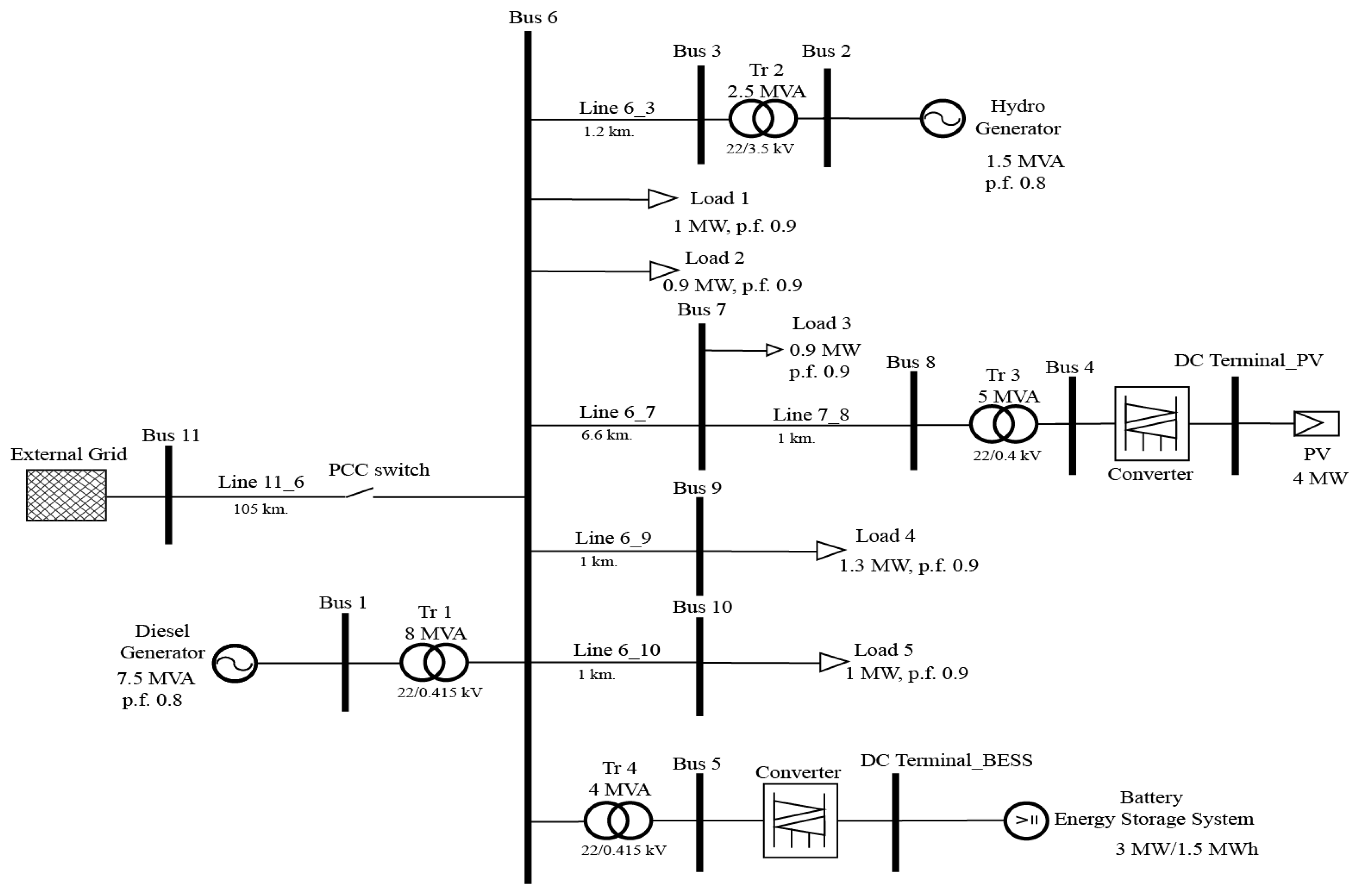
A pilot project of Mae Sariang’s microgrid system consists of a diesel power plant, a micro-hydro power plant, and a solar power plant without a BESS installed. Thus, this study focuses on the stabilization problems in the Mae Sariang’s microgrid system. Recently, several designed concepts of BESS have been tested on a Real Time Digital Simulator (RTDS). For example, in [
16], the conceptual of microgrid system (as in
Figure 1.) was tested on an RTDS to study a critical clearing time of overcurrent protection.
This study is inspired by the features of the ESS discussed earlier with a focus on improving the frequency/voltage stability in the Mae Sariang’s microgrid system in the case of an islanding condition. The fuzzy logic control and robust control methods are applied for the active and reactive power controls of the BESS in the microgrid during contingencies, to stabilize the frequency and voltage dynamic responses. The simulation results are implemented on the DIgSILENT PowerFactory software.
3. The Control Method of BESS
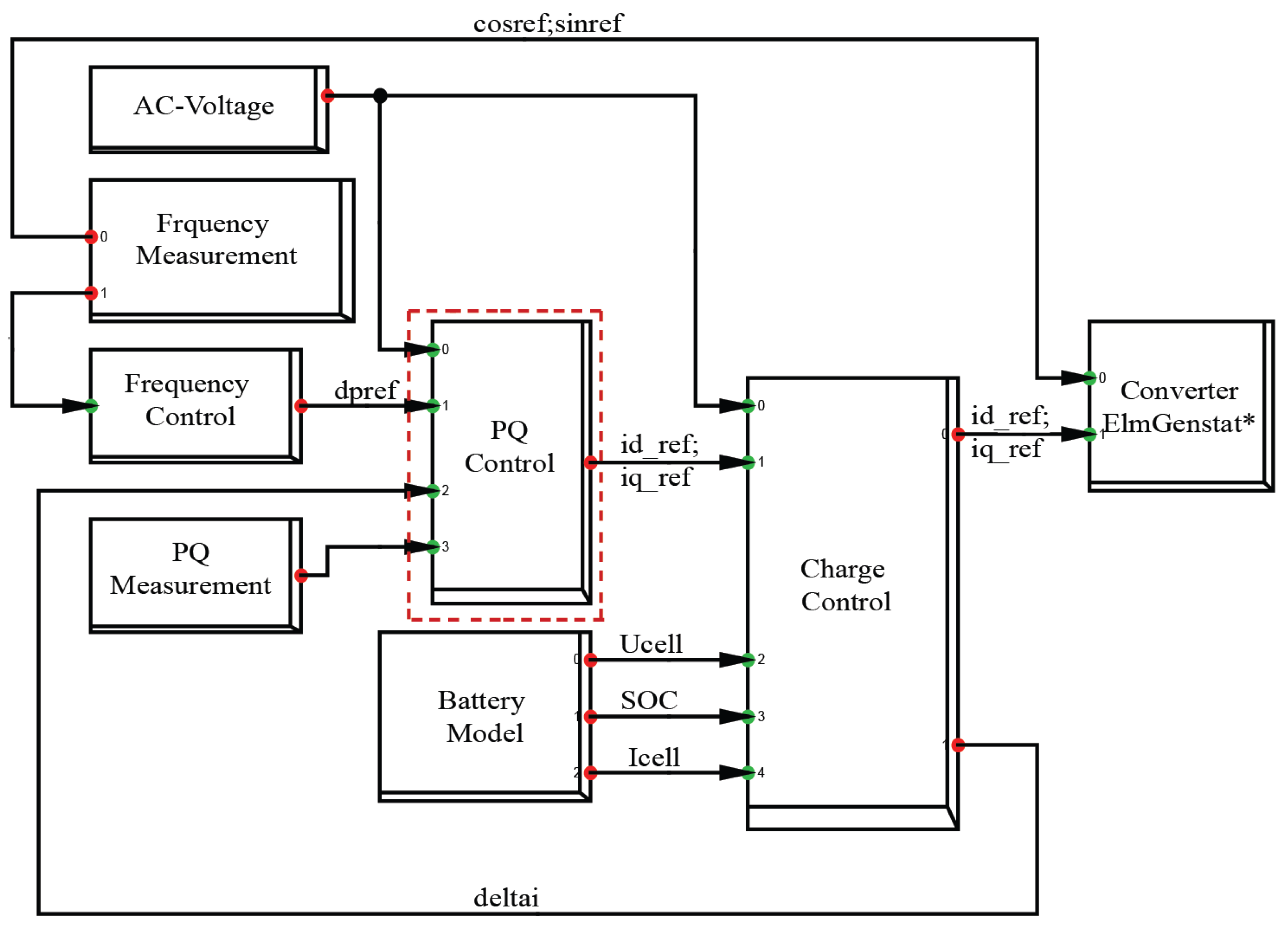
The BESS control method is the emphatic part of this study, as exhibited in the PQ control block in
Figure 3. It is composed of the active power controller of the BESS part (the P controller) and the reactive power controller of the BESS part (the Q controller). The signal of the active power is sent to the loop of the P controller and the signal of the reactive power is sent to the loop of the Q controller. Further, the output signal is transmitted to the converter and is finally sent back to the microgrid, to minimize the frequency and voltage deviations. When disturbances appear in the microgrid, it may result in the active and reactive power fluctuations and lead to the frequency and voltage deviations. Hence, such fluctuations can be eliminated by the equilibrium control between the power that supplies and the power demand through the BESS control.
Since decades, the fuzzy logic control method has been a widely used scheme, especially in the field of control systems, and it is a highly efficient control method. This method is based on the knowledge and experience of experts, serving as a basis for the intelligent designs, so such method has a human intelligence. Moreover, this method does not require accurate numerical modeling of the system, making it perfect for complex ambiguous, uncertainty, and multi-input systems. The fuzzy logic control method comprises four main parts: fuzzification, control rules, inference system, and defuzzification [
25]. In this study, the fuzzy logic control and robust control approaches are applied for the BESS control. The details for each method are demonstrated in
Section 3.1 and
Section 3.2, respectively.
3.1. Establishment of Fuzzy Logic Control
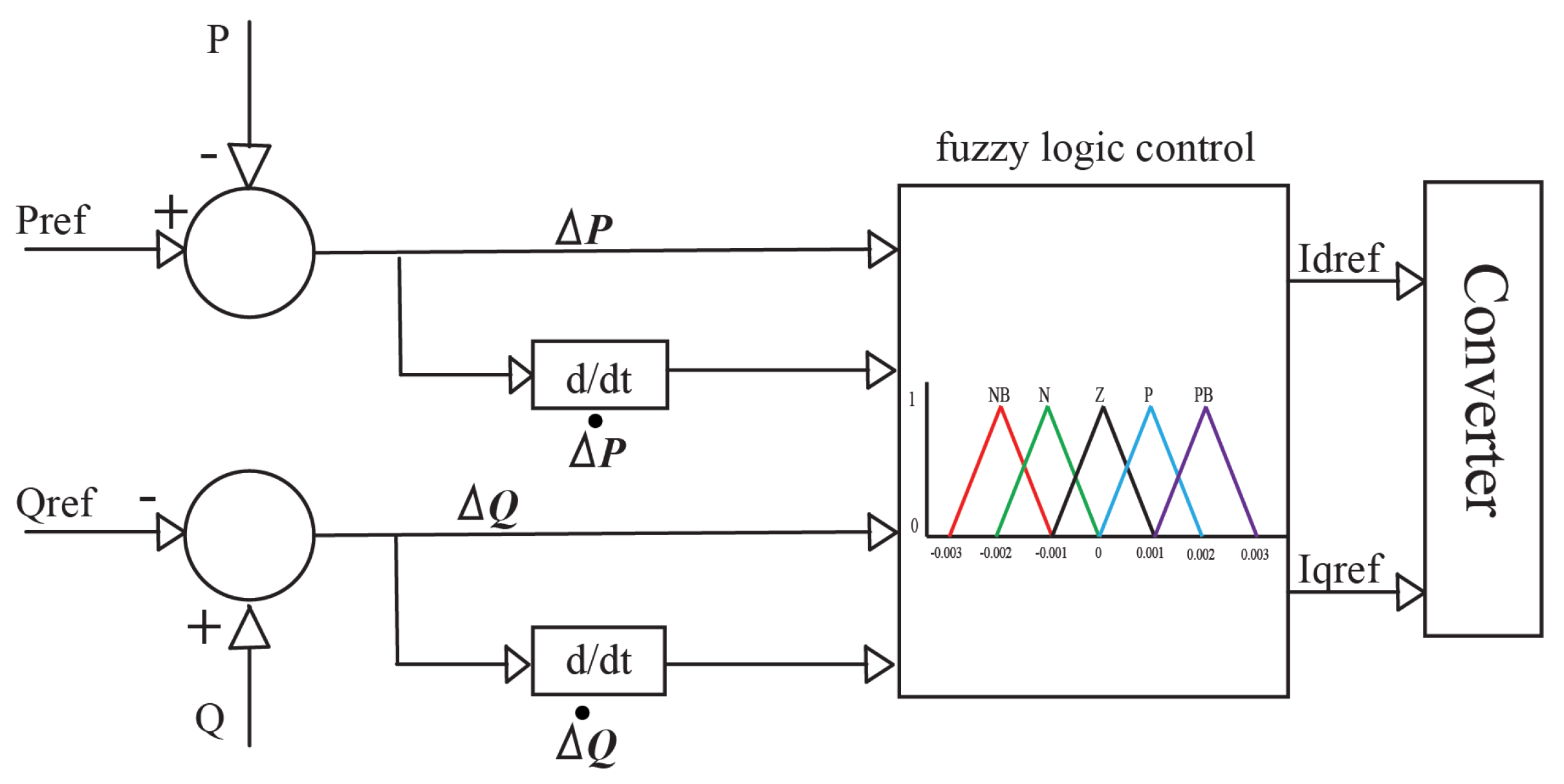
The fuzzy logic control method is applied with the BESS controller to maintain frequency and voltage stability within the desirable microgrid performance/constraint. The PQ control part inside (see in
Figure 3) is the proposed BESS fuzzy logic controller as demonstrated in
Figure 4.
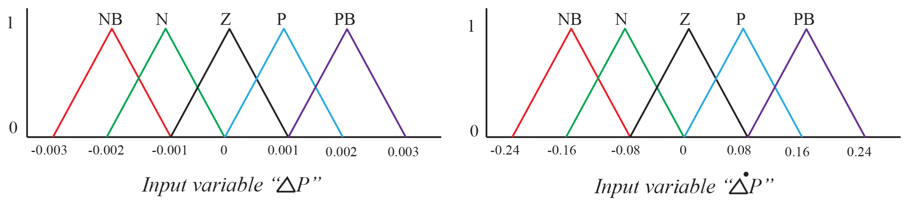
is the error and
is the BESS active power deviation of the error being the input signal.
is the output signal of the P controller part. These two inputs are divided into five input triangular membership functions;
(Negative Big),
N (Negative),
Z (Zero),
P (Positive), and
(Positive Big) as demonstrated in
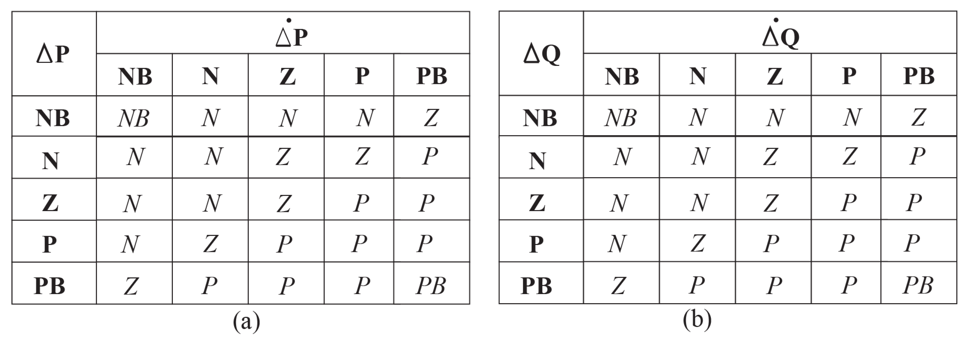
Figure 5. The control rules are indicated as follows: Rule 1: if
is
and
is
, then
should be
Z. These inputs have a total of 25 fuzzy logic control rules, including a convenient way to present a decision rule, which is to employ the decision tables as illustrated in
Figure 6a.
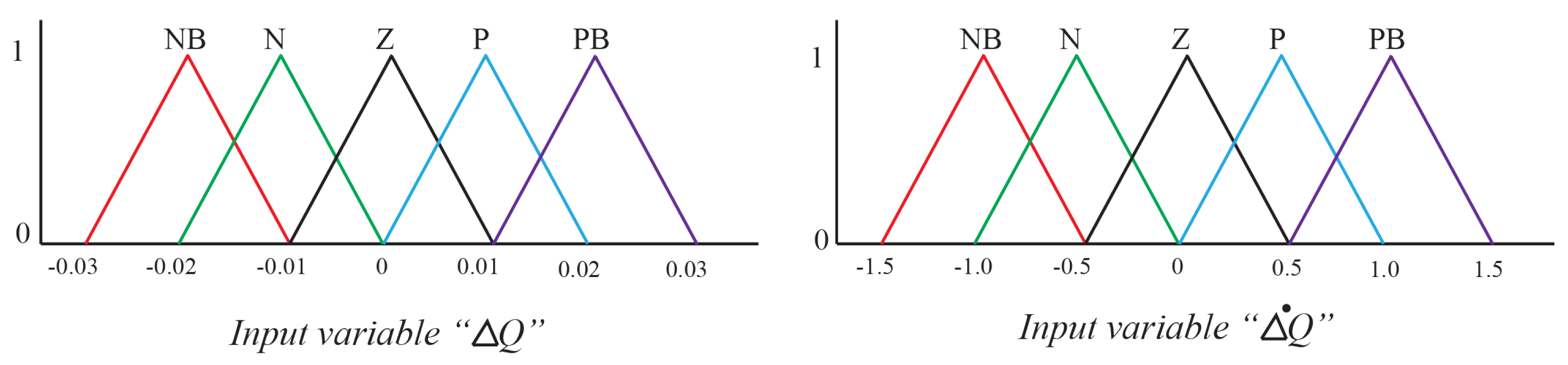
Similarly,
is the error and
is the change of the error of the BESS reactive power chosen to be the input signal.
is selected as the output signal of the Q controller part. The proposed method for determining of the membership functions and fuzzy logic control rules of the Q controller part is the same as the P controller part. The fuzzy rule base table and the membership function plots of the Q controller are illustrated in
Figure 6b and
Figure 7, respectively.
3.2. Establishment of Robust Control
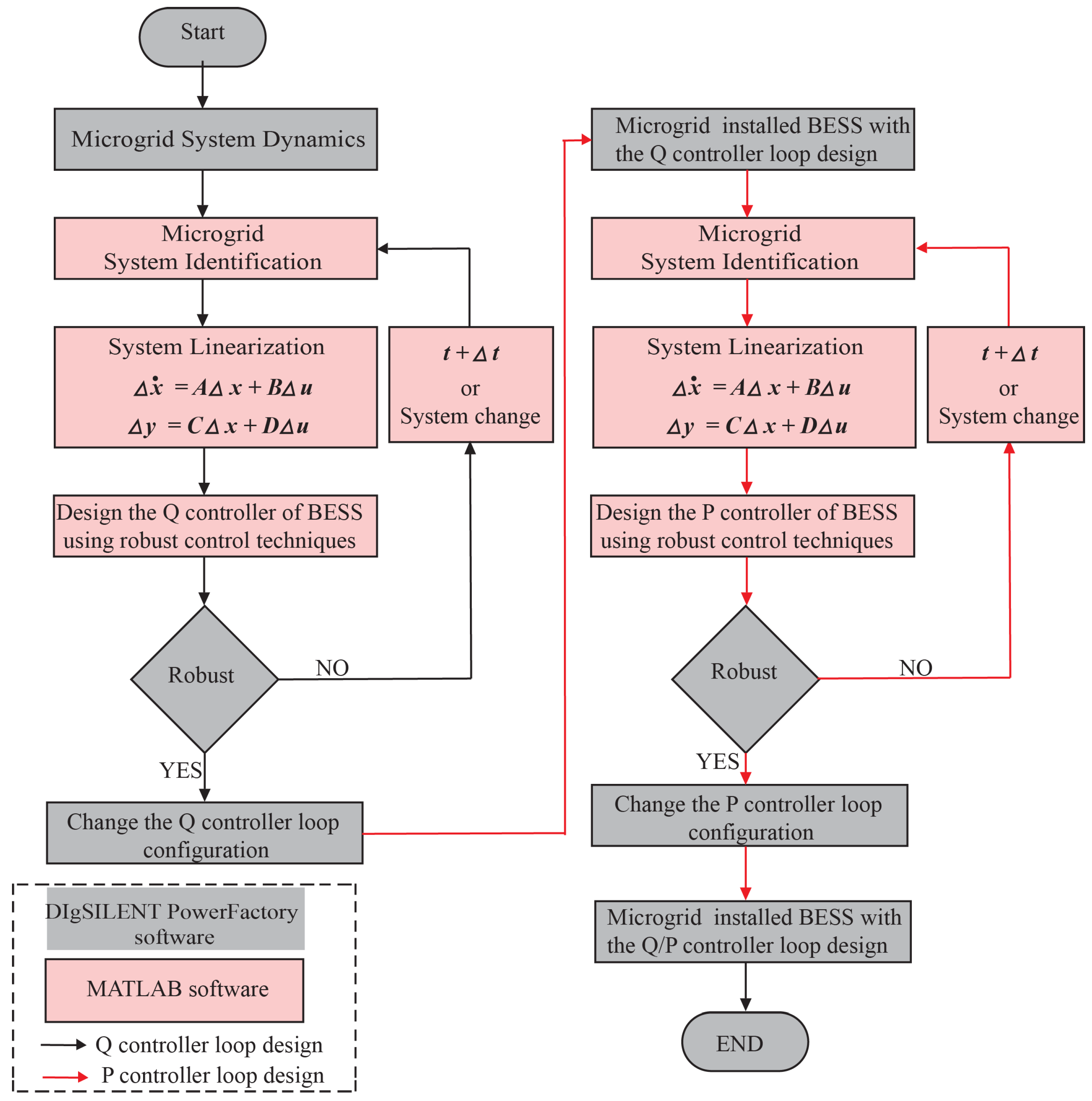
To examine the efficicency of the BESS fuzzy logic control method, the BESS robust control method is also designed for the frequency/voltage stabilization and improving the dynamic response in the islanded microgrid. In this study, the Q controller is primarily designed to maintain a steady voltage of the microgrid system and a perspective of the studied microgrid system analysis process is shown in
Figure 8. The process is expressed by the following steps.
Step 1: Formulate the microgrid model employed in this study using the DIgSILENT PowerFactory software, as demonstrated in
Figure 1.
Step 2: Create a mathematical model of the studied microgrid using the system identification technique, to design a robust BESS controller for the Q controller loop.
First, the input and output signals of the microgrid system are assigned. In this study, the q-axis component of the current fed into the converter (
) and the BESS reactive power deviation (△
Q) are the output and input signals of the Q controller loop design. The swept-frequency signal is injected at the input point. This process is accomplished by the DIgSILENT PowerFactory software. Second, the input and output signals are exported to the MATLAB software to obtain the appropriate transfer function of the microgrid system using the system identification technique. Further, the state-space equations of the microgrid system are established according to Equation (
1):
where
,
,
, and
are the input, output, and disturbance states, respectively, by assigning
,
,
,
, and
, which are the state estimation matrices.
Subsequently, the system linearization utilizing the gradient search is estimated to determine the applicable transfer function of the microgrid system, as expressed as
Step 3: Formulate the robust BESS controller.
from the previous step is administered for the robust BESS controller utilizing the robust control strategy. It has the following processes: First, choose the weighting transfer functions (
), which are selected based on low frequency response to offer the gain of the small sensitivity function at such frequency range. Second,
is applied for determining the plant transfer function (
), as written in Equation (
3).
where
is a lead compensator, and
is a lag compensator of the Q controller loop.
Third, establish the transfer function of the perturbed plant (
) to formulate the extent of the robust stability via
factor according to Equation (
4).
Figure 9 demonstrates the robust stability problem.
where
,
,
, and
are the transfer functions of the uncertainties of the plant
and assigning
.
Subsequently, create the BESS controller (
) of the Q controller loop as shown in the yellow part of
Figure 9, and
can be computed by Equation (
5). The first loop is defined to
. Further, the value of
is reduced until
, and this value is the most appropriate for the robust controller.
However, since the study of the microgrid system is complicated, the designed controller usually has a high order, and the controller is implemented as a second-order arrangement. Thereby, this study needs to reduce the order of controller using the suitable reduction strategy in the robust control toolbox of MATLAB [
26]. Finally, for the Q controller loop design,
is supplanted in constituent of the Q controller loop part. This process is accomplished utilizing the DIgSILENT PowerFactory software.
Finally, the reasonable transfer function for the Q controller loop can be represented in Equation (
6):
Step 4: Design the robust BESS controller () for the P controller loop.
has similar design processes with the Q controller loop. However, the microgrid system includes the robust Q controller loop of the BESS, which is applied for the P controller loop design. The d-axis component of the current is fed into the converter (
) and the BESS real power deviation (△
P) is the output/input signal of the P controller loop design. The robust stability problem structure is shown in the gray shaded blocks of
Figure 9. The BESS robust controller for the Q and P controller loops can be represented in Equations (
7)–(
8), respectively. The state-space matrices (
A,
B,
C, and
D) and the weighting transfer functions (
) are shown in
Appendix B.
Eventually, the achievement appraisal of the proposed robust BESS control is accomplished in
Section 4.
4. Simulation Results
The microgrid is illustrated in
Figure 1. It is used to investigate the control algorithms of the active and reactive power injections of the BESS, to maintain frequency and voltage stability in the microgrid. In this study, the maximum allowable frequency and voltage change is simulated to 5 % for its nominal value. The simulation was executed for 30 s in the DIgSILENT PowerFactory software.
To examine the performance of the proposed BESS controller in this study, two different scenarios were simulated, and each scenario was divided into three comparison cases as follows: Case I: the microgrid without a BESS, Case II: the microgrid with a BESS fuzzy logic controller, and Case III: the microgrid with a BESS robust controller.
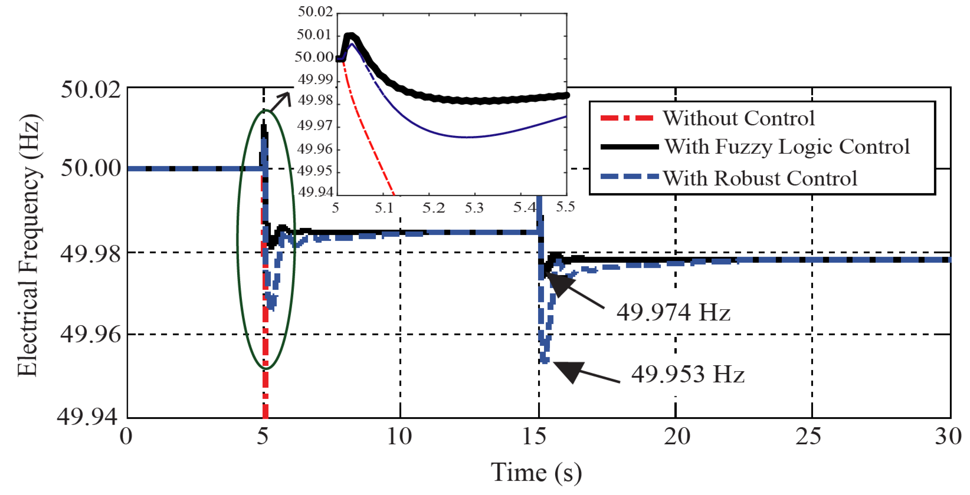
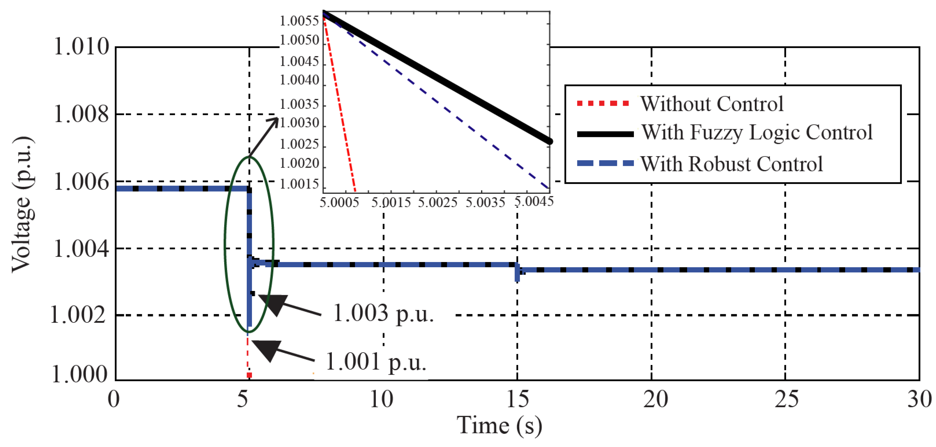
Scenario I: The microgrid operates in the islanded mode and has a very low inertia behavior. The simulation is executed for 30 s. The PCC switch is opened after 5 s, which indicates the isolation of the microgrid. The microgrid is then operated in the islanded mode for 15 s, and the hydro generator is then disconnected from the microgrid. This is an occurrence of the severe input disturbance. The frequency and voltage responses of the microgrid at Bus 6 and the management of the power generation in Scenario I demonstrated in
Figure 10 and
Figure 11, respectively. When the microgrid operates in the islanded mode, the frequency and voltage is rapidly changed due to the variations of the power unbalance between the supply and demand in the microgrid. In Case I, as demonstrated in the red line, it cannot maintain the microgrid stability. However, in Cases II and III, it can maintain the frequency and voltage within the acceptable range as demonstrated in black and blue lines, respectively. The amplified windows of
Figure 10 and
Figure 11 clearly show that the rate of change of frequency (df/dt) of Case I is equal to −0.488 Hz/s, while the df/dt of Case II and Case III are equal to −0.076 Hz/s and −0.185 Hz/s, respectively. Likewise, the rate of change of voltage (dV/dt) of Cases I, II, and III are equal to −8 p.u./s (or 176 V/ms), −0.6 p.u./s (or 13.2 V/ms), and −1 p.u. /s (or 22 V/ms), respectively.
At 15 s, the hydro generator is disconnected from the microgrid, resulting in frequency and voltage fluctuations. This issue can be solved by utilizing the BESS in Cases II and III. However, in the case of the microgrid with a BESS fuzzy logic controller installed (Case II) outperforms Case III (the microgrid with a BESS robust controller installed). In Case II, when disturbance occurs, the frequency becomes the lowest at 49.974 Hz, and the lowest voltage is 1.003 p.u. The frequency is rapidly restored to a constant value within 1 s, which is considered a highlight in this case.
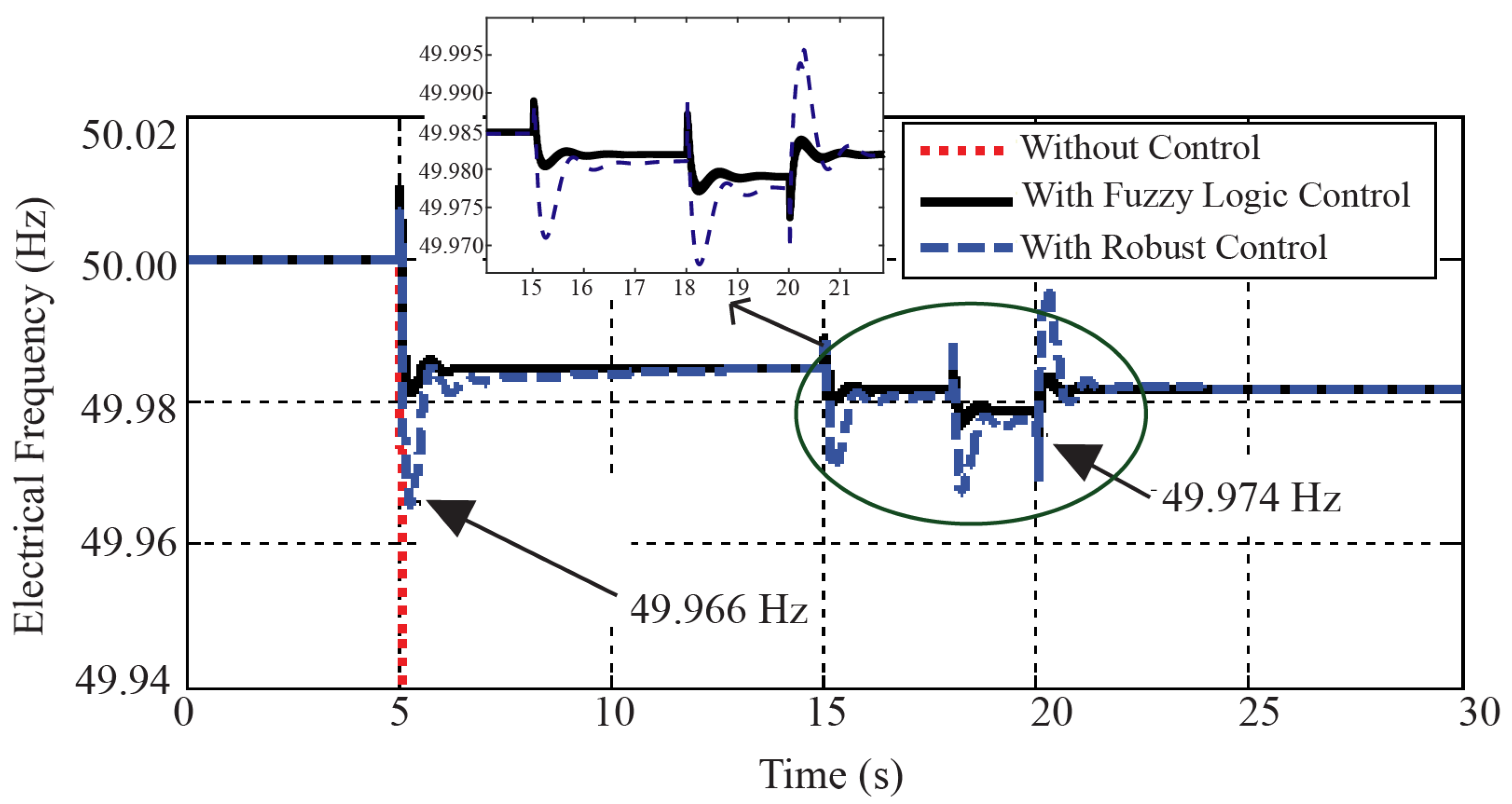
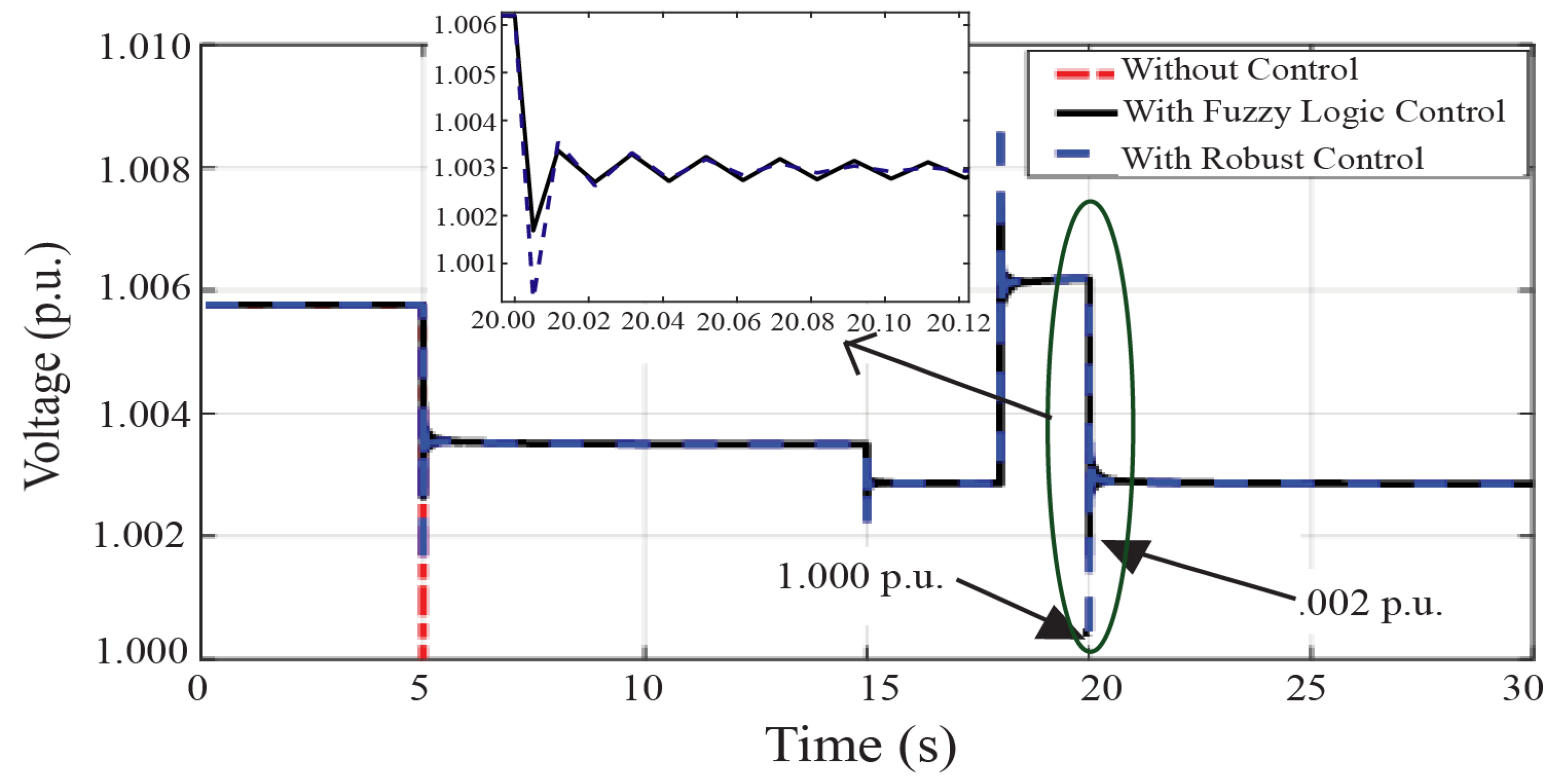
Scenario II: The microgrid operates in the islanded mode and has a high inertia behavior, with an increase in the load and uncertainty of the PV.
The simulation is executed for 30 s. The microgrid initially operates in the islanded mode at 5 s. At 15 s, Load 1 is increased by 50% from its nominal value, and the PV is then deactivated at 15–18 s.
Figure 12 and
Figure 13 indicate the frequency and voltage responses at Bus 6 in Scenario II, respectively. The blue line represents the frequency and voltage at Bus 6 of the BESS robust controller case and the black line is the frequency and voltage at Bus 6 of the BESS fuzzy logic controller case. It can be observed that, after the disturbance, the blue line has a minimum frequency of
Hz and has a minimum voltage of
p.u., while the frequency and voltage changes in a black line is small. In other words, the case where a BESS fuzzy logic controller is installed is superior in terms of frequency and voltage responses, with excellent resistance to disturbances. Hence, this case can effectively maintain the balance between the power supply and power demand in the island mode of the microgrid. These can be confirmed in the amplified windows of
Figure 12 and
Figure 13, showing that the BESS fuzzy logic controller has a better response.
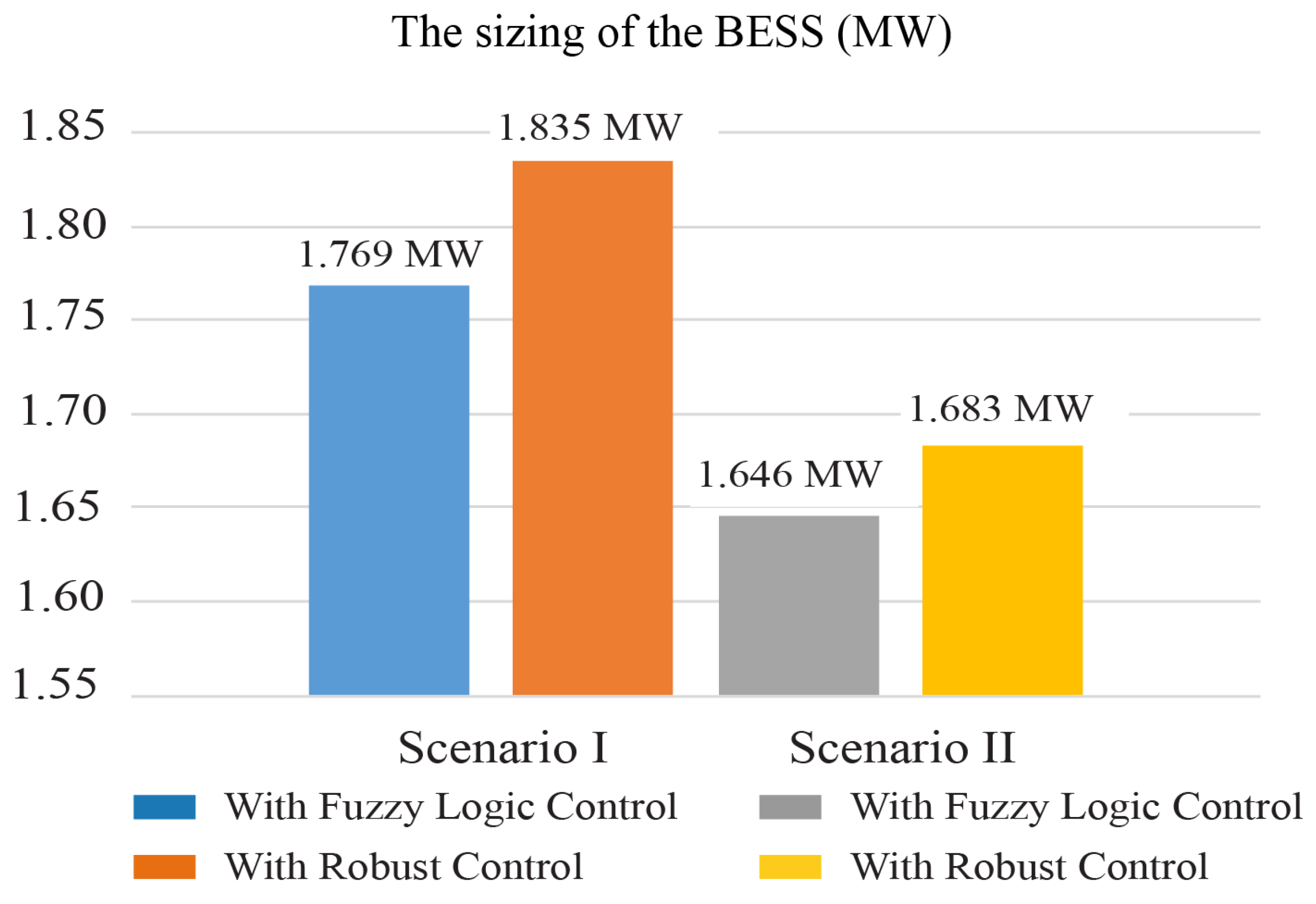
Figure 14 illustrates comparison results of the BESS sizing used to improve the dynamic stability of the microgrid. The rated capacity of BESS is equal to 3 MW (1.5 MWh). The state of charge (SOC) is kept between 20 and 80 % of the rated capacity (0.3 MWh to 1.2 MWh) for both absorption and injection. In Scenario I, the BESS capacity with a fuzzy logic controller is equal to 0.589 MWh (1.769 MW) and it takes 30.53 min to supply the power to the load, while the BESS capacity with a robust controller is equal to 0.612 MWh (1.835 MW) and it takes 29.42 min. In Scenario II, the BESS capacity with a fuzzy logic controller and the power discharge duration time are equal to 0.548 MWh (1.646 MW) and 33.20 min, respectively. The BESS capacity with robust controller and the power discharge duration time are equal to 0.587 MWh (1.683 MW) and 32.09 min, respectively. Overall results shown that the BESS with fuzzy logic controller is more effective to improve the frequency/voltage stability [
27]. When the microgrid is disconnected from the main grid, the BESS can supply the power to the load for approximately 30 min. If the microgrid is reconnected to the main grid, the BESS will be charged and the SOC is kept 80. In the worst-case scenarios, if the microgrid cannot connect to the main grid and the BESS is fully discharged, the standby generator will supply the power to the local load.
5. Conclusions
This study addresses the enhanced performance of an islanded Mae Sariang microgrid utilizing a battery energy storage system (BESS) with a fuzzy logic controller. The proposed fuzzy logic control approach has an important feature that allows the BESS to rapidly respond to the output power uncertainties from RESs. To prove the performance of the proposed method, the design has been implemented on a Mae Sariang microgrid system. The verification has been performed using the DIgSILENT PowerFactory software. The performance of the proposed fuzzy logic control is compared with a well-known robust control to show the superiority of the proposed fuzzy logic control. The simulation results demonstrated that the proposed BESS fuzzy logic and robust controllers have allowed that the BESS can control the active and reactive power transfer in the microgrid during contingencies, reducing the frequency/voltage fluctuation.
However, the proposed fuzzy logic controller has been significantly examined and it provides a rapid recovery of the frequency and voltage. Moreover, the complications of the designed method have been better than the robust controller. Additionally, another highlight is the reduced energy density of the deployed BESS with the proposed fuzzy logic controller (1.769 MW for Scenario I and 1.646 MW for Scenario II), which is smaller than the BESS with robust controller.


 ,
, 
