Surface Water Resource Protection in a Mining Process under Varying Strata Thickness—A Case Study of Buliangou Coal Mine, China

 ,
,
Abstract
:1. Introduction
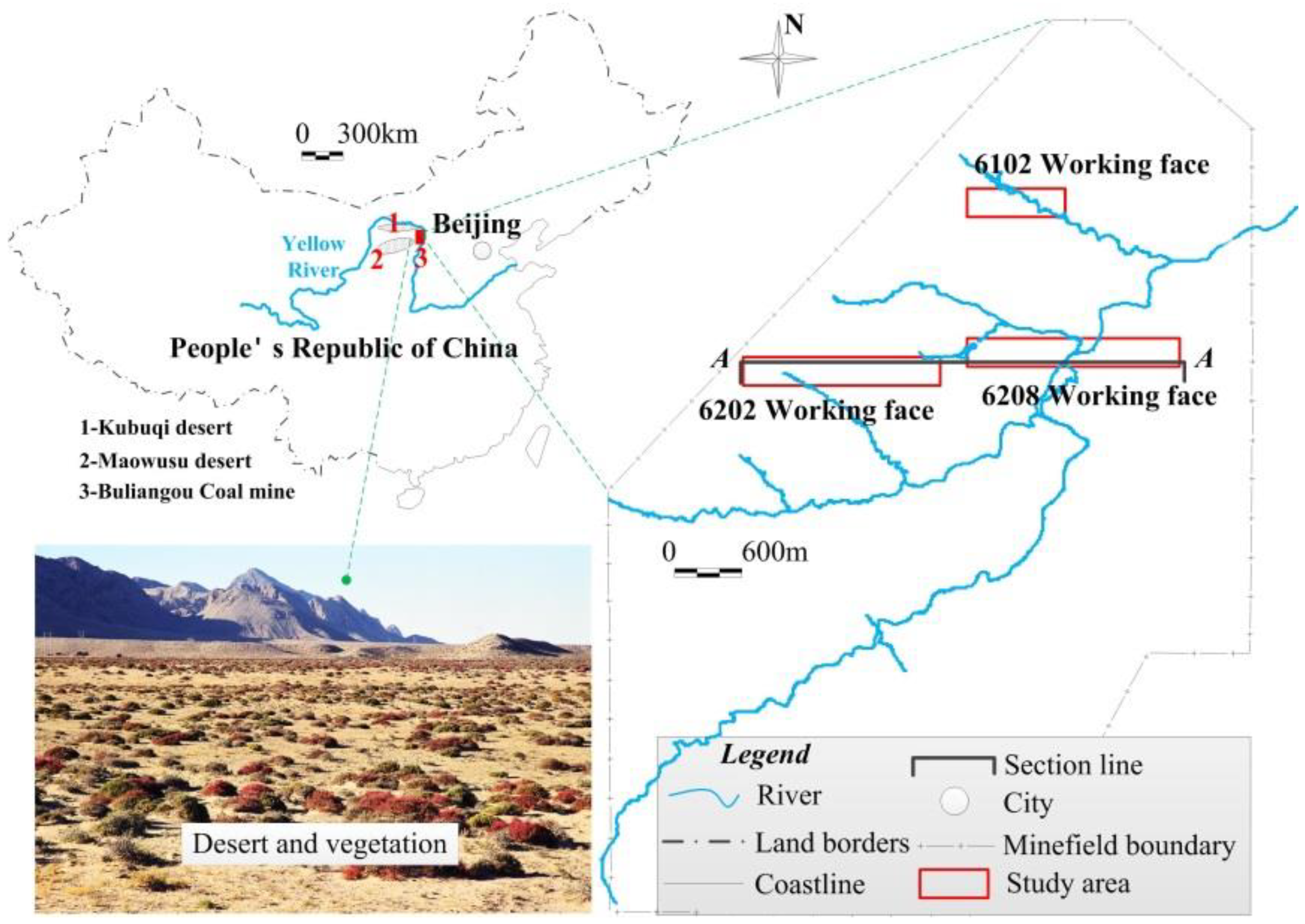
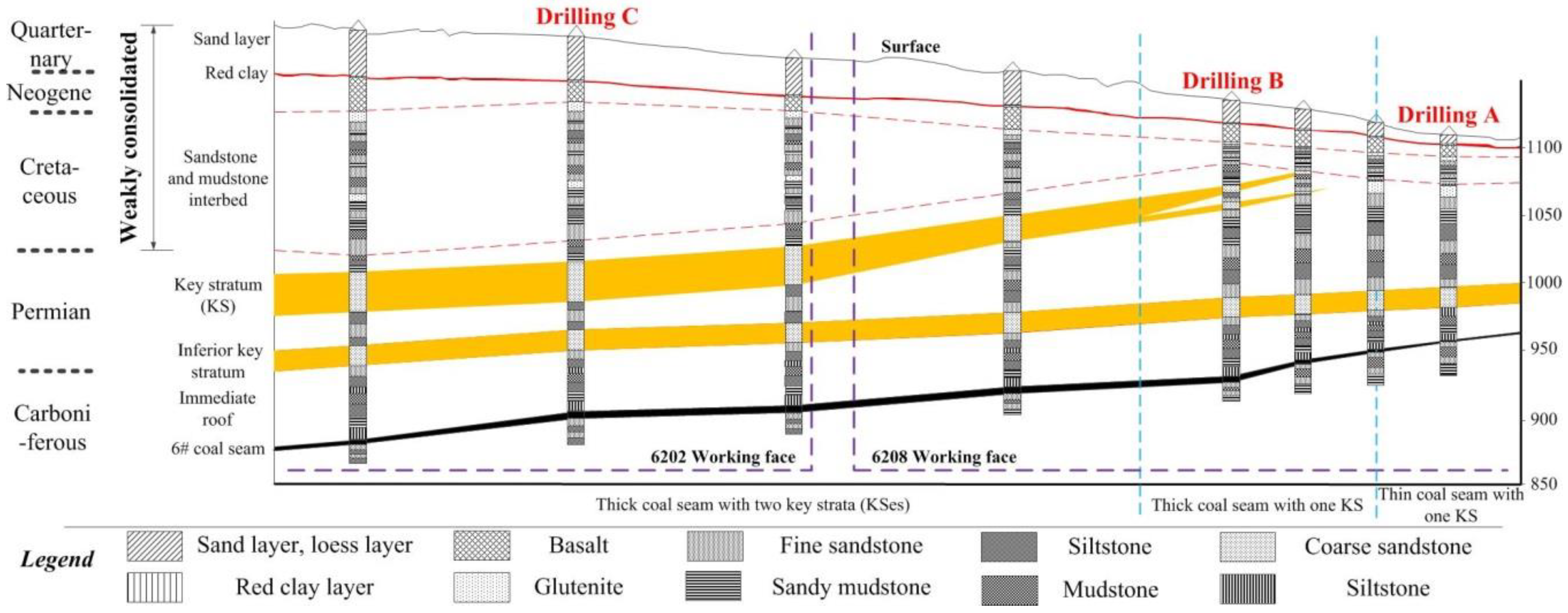
2. Study Area
2.1. Overview of Buliangou Mine
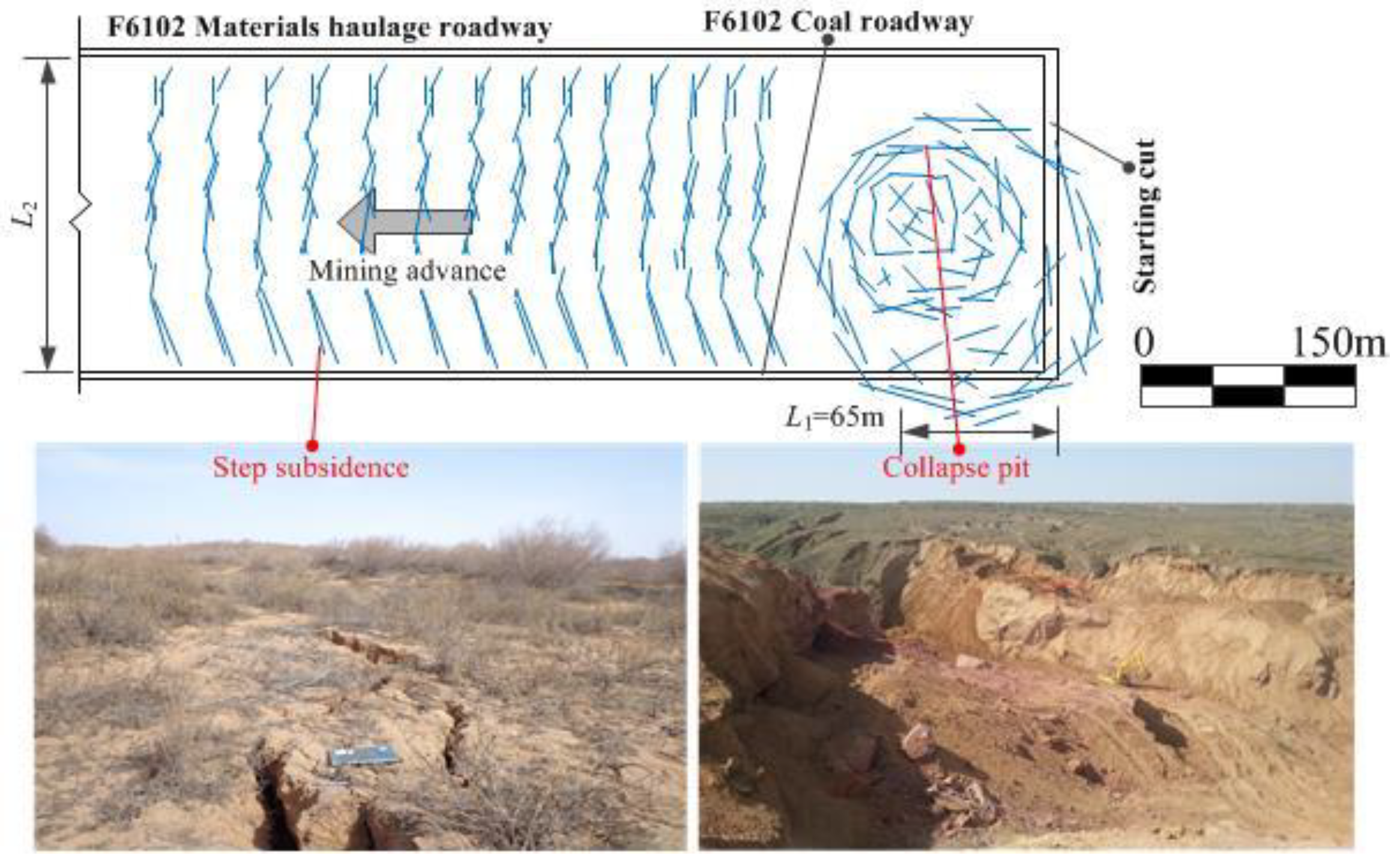
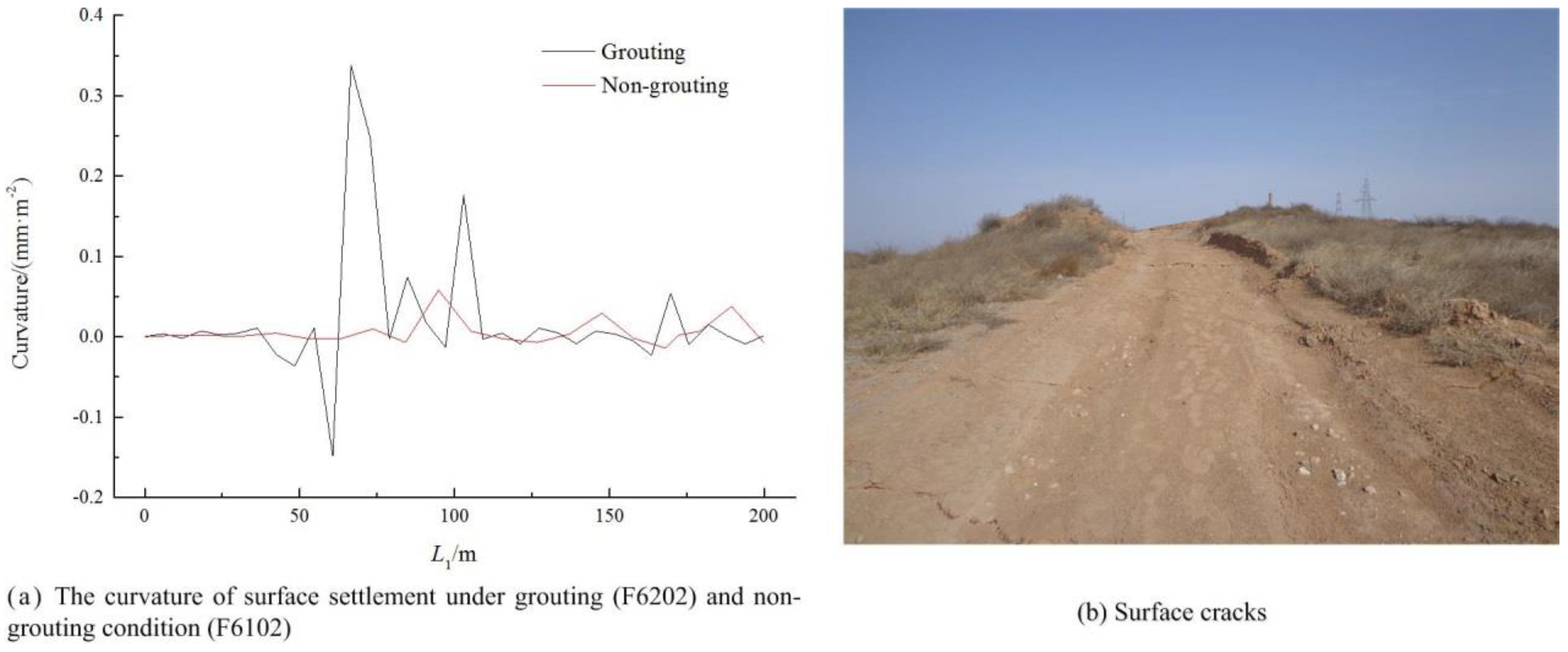
2.2. Mining Consequences in F6102 Working Face
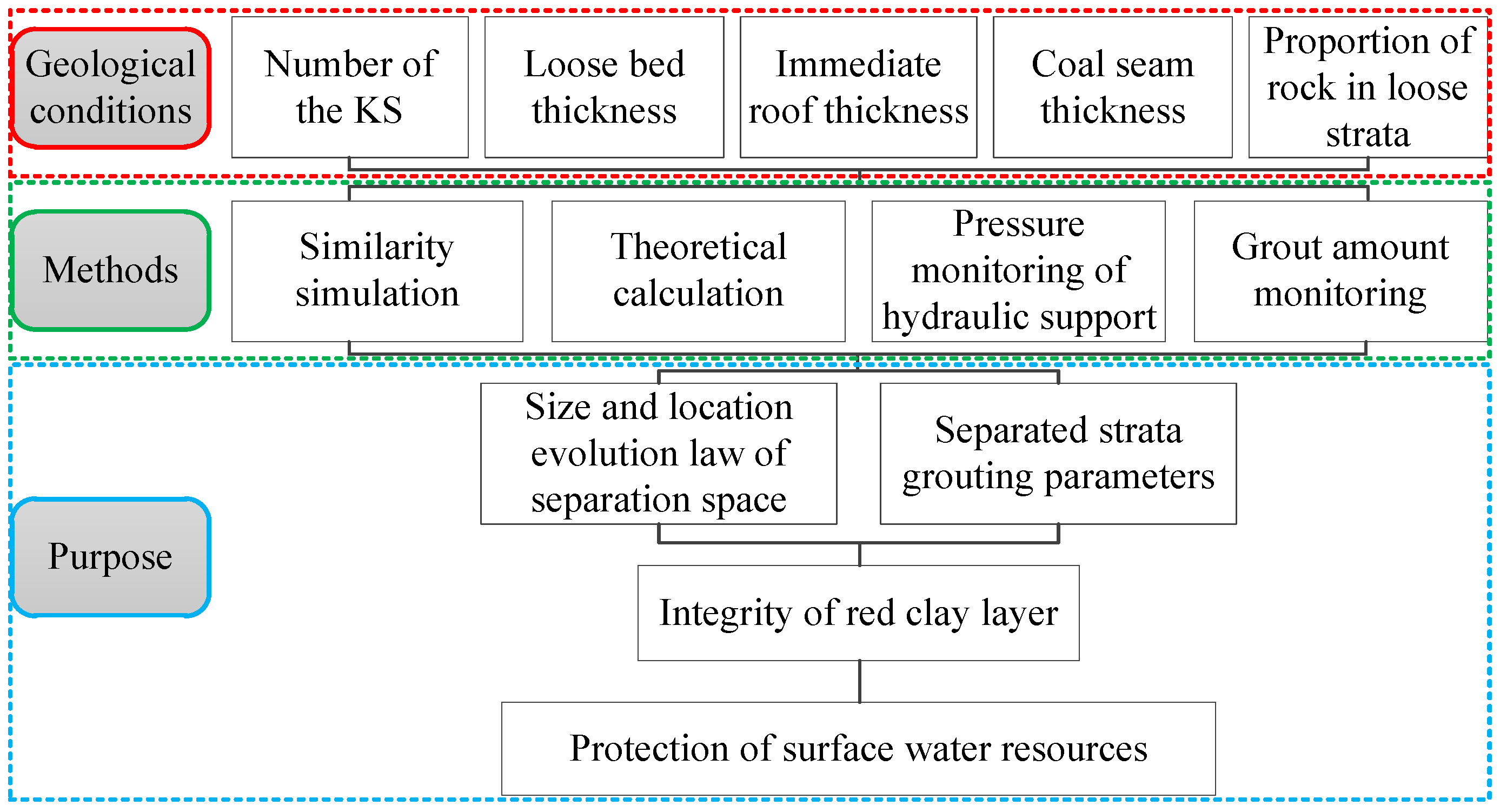
3. Methods
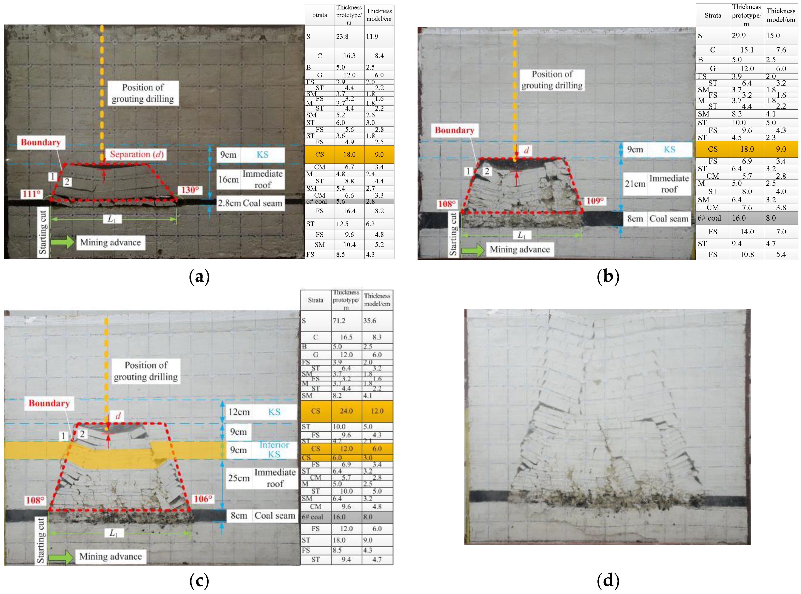
3.1. Similar Simulation Tests
3.1.1. Structure Formed by Broken Strata
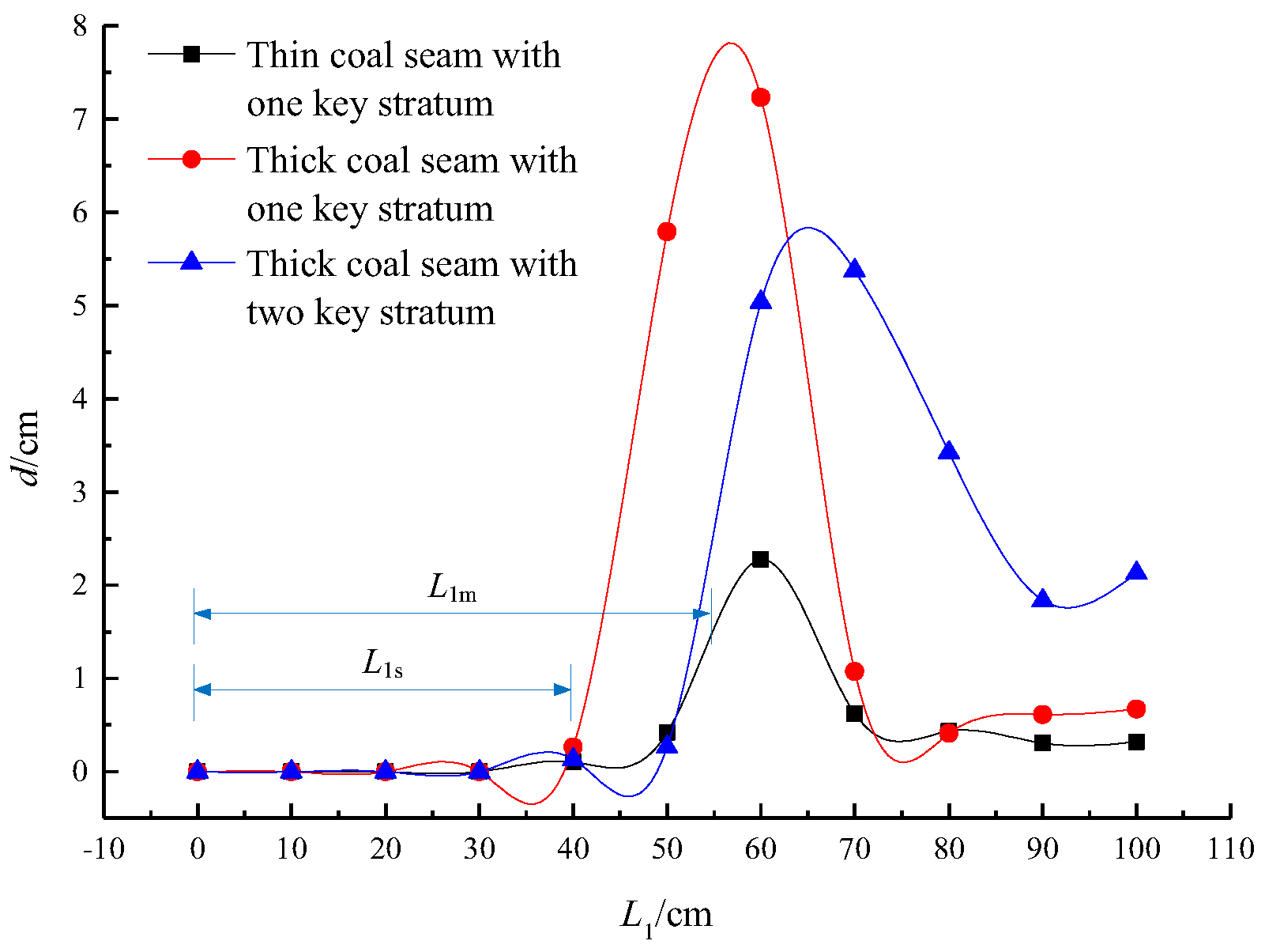
3.1.2. Range of Strata Separation under the KS
3.2. Theoretical Calculations
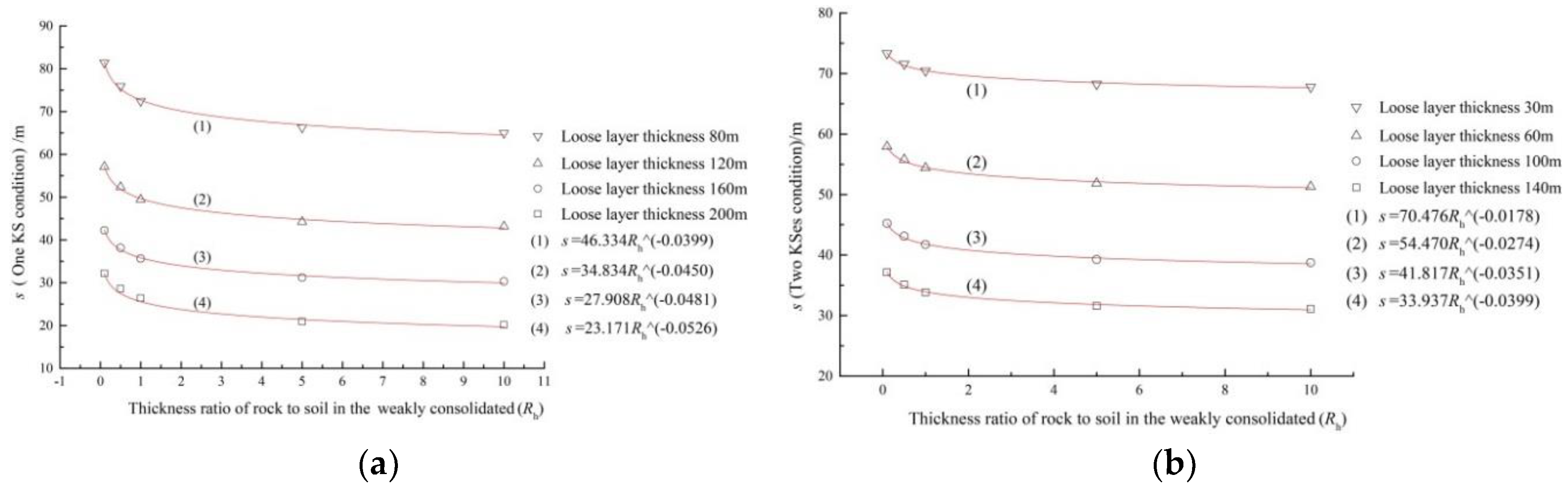
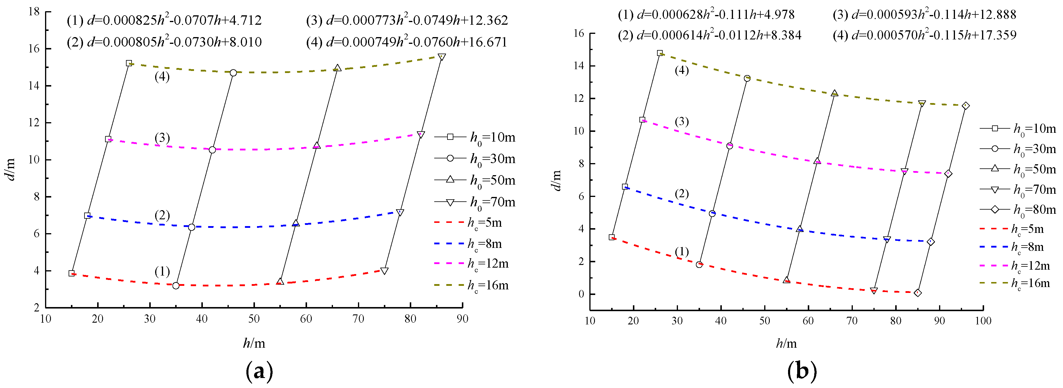
3.2.1. Equations for Geometric Parameters of Separation Space
3.2.2. Evolutionary Law of Separation Range
4. Grouting Scheme, Results, and Discussion
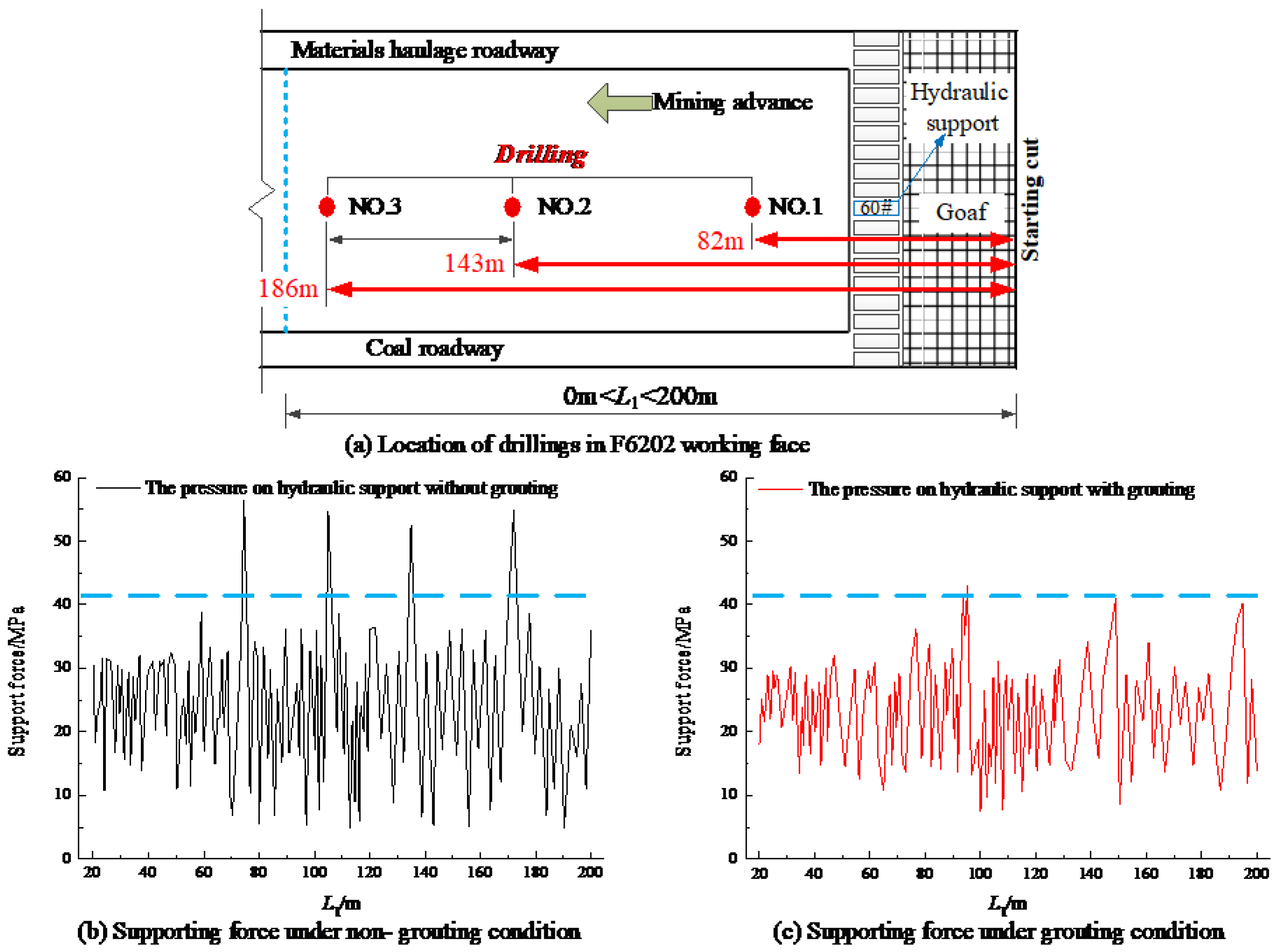
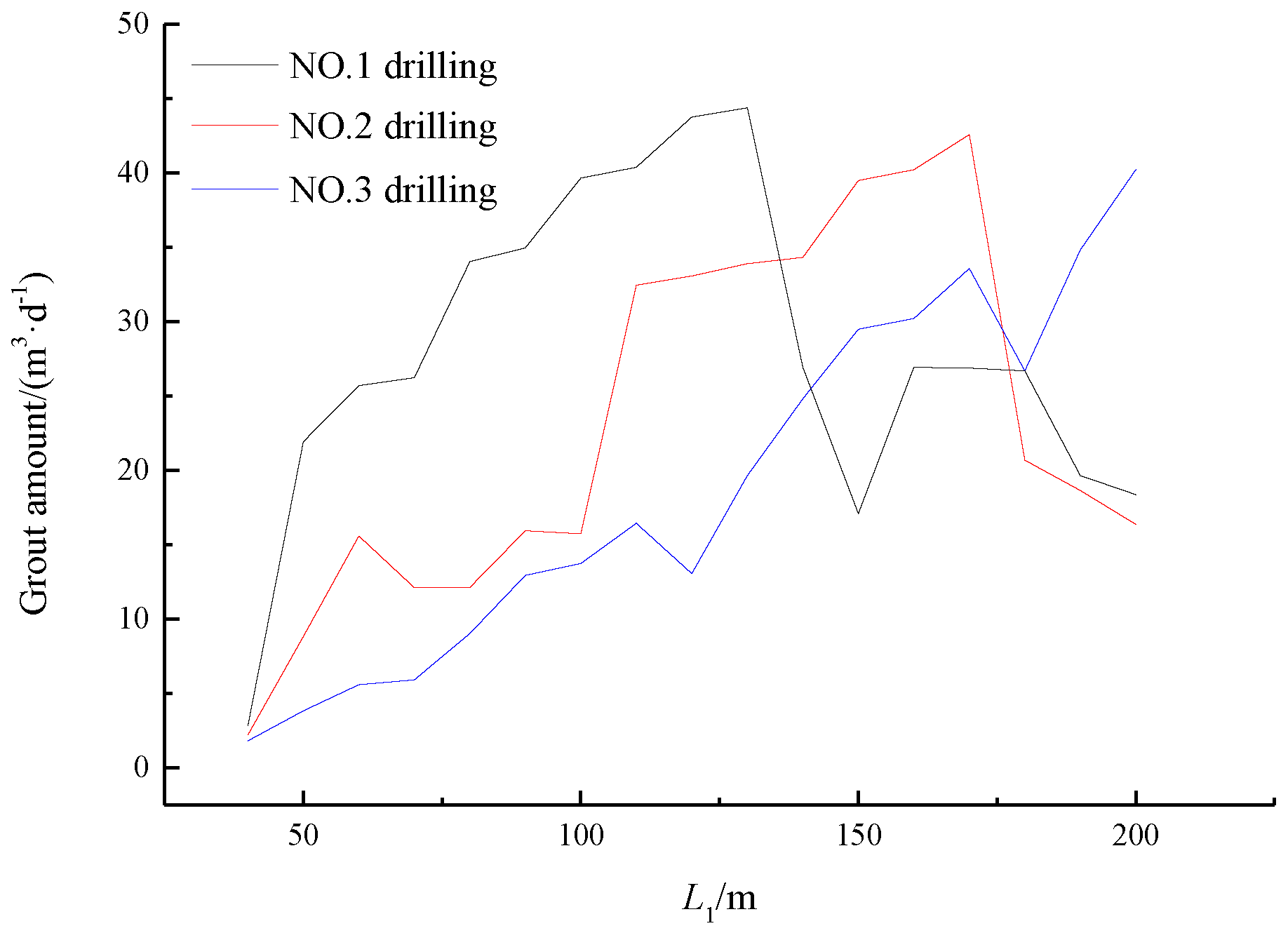
4.1. Practice and Results of Separated Strata Grouting
4.2. Discussion
5. Conclusions
Author Contributions
Funding
Acknowledgments
Conflicts of Interest
References
- Mariano, D.A.; Santos, C.A.C.D.; Wardlow, B.D.; Anderson, M.C.; Schiltmeyer, A.V.; Tadesse, T.; Svobodaa, M.D. Use of remote sensing indicators to assess effects of drought and human-induced land degradation on ecosystem health in northeastern Brazil. Remote. Sens. Environ. 2018, 213, 129–143. [Google Scholar] [CrossRef]
- Bernhardt, E.S.; Lutz, B.D.; King, R.S.; Fay, J.P.; Carter, C.E.; Helton, A.M.; Campagna, D.; Amos, J. How Many Mountains Can We Mine? Assessing the Regional Degradation of Central Appalachian Rivers by Surface Coal Mining. Environ. Sci. Technol. 2012, 46, 8115–8122. [Google Scholar] [CrossRef] [PubMed]
- Howladar, M.F. Coal mining impacts on water environs around the Barapukuria coal mining area, Dinajpur, Bangladesh. Environ. Earth. Sci. 2013, 70, 215–226. [Google Scholar] [CrossRef]
- Shipra, S.; Masto, R.E.; Ram, L.C.; Selvi, V.A.; Srivastava, N.K.; Tripathi, R.C.; George, J. Rhizosphere soil microbial index of tree species in a coal mining ecosystem. Soil. Biol. Biochem. 2009, 41, 1824–1832. [Google Scholar]
- Zhang, Q.; Wang, F.; Chen, M. Study on Wetland Connectivity Technology in the Urban Coalmine Subsidence Area of Huaibei, China—Hydrological Guarantee Analysis. Wetlands 2014, 34, 841–852. [Google Scholar] [CrossRef]
- Esaki, T.; Djamaluddin, I.; Mitani, Y.; Zhao, X.D. Development of gis-based evaluation support system for environmental protection against coal mining subsidence. Shigen-to-sozai 2006, 10, 513–521. [Google Scholar] [CrossRef]
- Yan, W.; Dai, H.; Chen, J. Surface crack and sand inrush disaster induced by high-strength mining: Example from the Shendong coal field, China. Geosci. J. 2017, 22, 1–11. [Google Scholar] [CrossRef]
- Seedsman, R.W. Geotechnical sedimentology—Its use in underground coal mining. Int. J. Coal Geol. 2001, 45, 147–153. [Google Scholar] [CrossRef]
- Zhu, G.A.; Dou, L.M.; Cao, A.Y.; Cai, W.; Wang, C.B. Assessment and analysis of strata movement with special reference to rock burst mechanism in island longwall panel. J. Cent. South. Univ. 2017, 24, 2951–2960. [Google Scholar] [CrossRef]
- Nie, L.; Wang, H.; Xu, Y.; Li, Z. A new prediction model for mining subsidence deformation: The arc tangent function model. Nat. Hazards 2015, 75, 2185–2198. [Google Scholar] [CrossRef]
- Chen, L.; Zhang, S.; Gui, H. Prevention of water and quicksand inrush during extracting contiguous coal seams under the lowermost aquifer in the unconsolidated Cenozoic alluvium—A case study. Arab. J. Geosci. 2014, 7, 2139–2149. [Google Scholar] [CrossRef]
- Wu, Q.; Fan, Z.; Zhang, Z.; Zhou, W. Evaluation and zoning of groundwater hazards in Pingshuo No. 1 underground coal mine, Shanxi Province, China. Hydrol. J. 2014, 22, 1693–1705. [Google Scholar] [CrossRef]
- Luan, H.J.; Jiang, Y.J.; Lin, H.L.; Wang, Y.H. A New Thin Seam Backfill Mining Technology and Its Application. Energies 2017, 10, 2023. [Google Scholar] [CrossRef]
- Zhao, T.B.; Ma, S.Q.; Zhang, Z.Y. Ground Control Monitoring in Backfilled Strip Mining under the Metropolitan District: Case Study. Int. J. Geomech. 2018, 18, 1–14. [Google Scholar] [CrossRef]
- Chen, S.J.; Yin, D.W.; Cao, F.W.; Liu, Y.; Ren, K.Q. Comprehensive technology and development prospect of reducing subsidence in coal mine. Chin. Min. Mag. 2015, 24, 104–108. [Google Scholar]
- Chen, S.; Yin, D.; Cao, F.; Liu, Y.; Ren, K. An overview of integrated surface subsidence-reducing technology in mining areas of China. Nat. Hazards. 2016, 81, 1129–1145. [Google Scholar] [CrossRef]
- Booth, C.J. Groundwater as an environmental constraint of longwall coal mining. Environ. Geol. 2006, 49, 796–803. [Google Scholar] [CrossRef]
- Gandy, C.J.; Younger, P.L. Predicting Groundwater Rebound in the South Yorkshire Coalfield, UK. Mine Water Environ. 2007, 26, 70–78. [Google Scholar] [CrossRef]
- Bai, H.; Miao, X. Hydrogeological characteristics and mine water inrush prevention of late Paleozoic coalfields. J. Chin. Univ. Min Technol. 2016, 45, 1–10. [Google Scholar]
- Li, H.; Bai, H.; Wu, J.; Ma, Z.; Ma, K.; Wu, G.; Du, Y.; He, S. A Cascade Disaster Caused by Geological and Coupled Hydro-Mechanical Factors—Water Inrush Mechanism from Karst Collapse Column under Confining Pressure. Energies 2017, 10, 1938–1957. [Google Scholar] [CrossRef]
- Wang, K.; Xu, Y.; Fang, Y. The fault block movements and the formation of the structural features in Yongxia coalfield. Chin Coal. 2015, 41, 44–48. [Google Scholar]
- Pang, Y.F.; Zhang, H.S.; Liu, Y.L. The Latest Comprehensive Technical Manual for Hydrogeological Exploration and Prevention of Water in Coal Mines; Coal Mine Science and Technology Press: Beijing, China, 2013; pp. 265–284. [Google Scholar]
- Li, X.H.; Lu, Y.Y.; Kang, Y.; Rao, B.H. Simulation Technology of Rock Mechanics Experiment; Science Press: Beijing, China, 2007; pp. 1–12. [Google Scholar]
- Hu, Z.; Xie, Y.; Lai, H. Research on Similar Materials for a Large Immersed Tunnel Model Test. Mod. Tunn. Technol. 2015, 52, 114–118. [Google Scholar]
- Jiang, F.; Zhang, S.; Li, X.; Hong, C.; Li, M.; Yang, W. Experimental Study on Materials Blending Proportion for Preparation Simulated Uranium Ore Based on Orthogonal Design. Min. Metall. Eng. 2018, 38, 20–24. [Google Scholar]
- Shen, Y.; Rong, T.; Yang, G.; Yuan, Y.; Yang, Y.; Yu, X. Experimental study on ratio of quasi-sandstone similar material. Adv. Sci. Technol. Water Resour. 2016, 36, 75–79. [Google Scholar]
- Qian, M.; Shi, P. Rock Pressure and Strata Control; China University of Mining and Technology Press: Xuzhou, China, 2003; pp. 173–185. [Google Scholar]
- Wang, Z.Q.; Guo, Y.; Gao, Y.; Chen, C.F.; Li, P.F.; Wang, L.; Zhao, J.L. Study of grouting technology of overburden-separation to reduce ground subsidence in Huafeng coal mine. Chin. J. Rock. Mech. Eng. 2014, 33, 3249–3255. [Google Scholar]
- Ye, Q.; Wang, W.J.; Wang, G.; Jia, Z.Z. Numerical simulation on tendency mining fracture evolution characteristics of overlying strata and coal seams above working face with large inclination angle and mining depth. Arab. J. Geosci. 2017, 10, 82–95. [Google Scholar] [CrossRef]
- Jiang, L.J.; Mitri, H.S.; Ma, N.J.; Zhao, X.D. Effect of foundation rigidity on stratified roadway roof stability in underground coal mines. Arab. J. Geosci. 2016, 9, 1–12. [Google Scholar] [CrossRef]
- Ju, F.; Li, B.Y.; Guo, S.; Xiao, M. Dynamic characteristics of gangues during vertical feeding in solid backfill mining: A case study of the Wugou coal mine in China. Environ. Earth. Sci. 2016, 75, 1389–1402. [Google Scholar] [CrossRef]
- Li, H.Z.; Guo, G.L.; Zhai, S.C. Mining scheme design for super-high water backfill strip mining under buildings: A Chinese case study. Environ. Earth. Sci. 2016, 75, 1017. [Google Scholar] [CrossRef]


| Lithology | Material and Mixing Ratio | Rock Mechanical Parameters under Natural Conditions | ||||||
|---|---|---|---|---|---|---|---|---|
| River Sand | Gypsum | Calcium Carbonate | Vaseline | Loess | Elastic Modulus (GPa) | Body Force (KN·m−3) | Tensile Strength (MPa) | |
| Soil | 7.2 | 0.4 | 1 | - | - | 1.5 | 17 | - |
| Sand | 10.0 | 0.4 | 1 | - | - | 3.0 | 18 | - |
| Red clay | 0.5 | - | - | 0.1 | 1 | 2.2 | 20 | - |
| Basalt | 7.1 | 0.5 | 1 | - | - | 20.4 | 25 | - |
| Glutenite | 8.5 | 0.4 | 1 | - | - | 31.2 | 25 | 2.1 |
| Sandy mudstone | 9.9 | 0.4 | 1 | - | - | 17.2 | 25 | 1.7 |
| Coarse sandstone | 14.3 | 1 | 1 | - | - | 28.5 | 25 | 3.8 |
| Fine sandstone | 10.5 | 0.5 | 1 | - | - | 20.2 | 25 | - |
| Siltstone | 9.3 | 0.3 | 1 | - | - | 17.6 | 25 | - |
| Carbon mudstone | 8.5 | 0.4 | 1 | - | - | 16.1 | 25 | - |
| Coal | 9.8 | 0.4 | 1 | - | - | 1.03 | 18 | - |
| Mudstone | 8.2 | 0.5 | 1 | - | - | 19.2 | 25 | - |
| Drilling Position | Grouting Pressure | Grouting Material |
|---|---|---|
| L1’ = 82 m, 143 m, 186 m | 2.8 MPa | Mixture of water, loess, and fly ash |
© 2018 by the authors. Licensee MDPI, Basel, Switzerland. This article is an open access article distributed under the terms and conditions of the Creative Commons Attribution (CC BY) license (http://creativecommons.org/licenses/by/4.0/).
Share and Cite
Li, H.; Zhang, B.; Bai, H.; Wu, J.; Meng, Q.; Xiao, N.; Li, F.; Wu, G. Surface Water Resource Protection in a Mining Process under Varying Strata Thickness—A Case Study of Buliangou Coal Mine, China. Sustainability 2018, 10, 4634. https://doi.org/10.3390/su10124634
Li H, Zhang B, Bai H, Wu J, Meng Q, Xiao N, Li F, Wu G. Surface Water Resource Protection in a Mining Process under Varying Strata Thickness—A Case Study of Buliangou Coal Mine, China. Sustainability. 2018; 10(12):4634. https://doi.org/10.3390/su10124634
Chicago/Turabian StyleLi, Hao, Boyang Zhang, Haibo Bai, Jianjun Wu, Qingbin Meng, Ning Xiao, Feng Li, and Guangming Wu. 2018. "Surface Water Resource Protection in a Mining Process under Varying Strata Thickness—A Case Study of Buliangou Coal Mine, China" Sustainability 10, no. 12: 4634. https://doi.org/10.3390/su10124634
APA StyleLi, H., Zhang, B., Bai, H., Wu, J., Meng, Q., Xiao, N., Li, F., & Wu, G. (2018). Surface Water Resource Protection in a Mining Process under Varying Strata Thickness—A Case Study of Buliangou Coal Mine, China. Sustainability, 10(12), 4634. https://doi.org/10.3390/su10124634