1. Introduction
Powertrain development for individual transport of the future will be substantially driven by regional statutory emission limits [
1], the mobility preferences of customers, and the economic circumstances of manufacturers. The automotive industry will need to address this challenging, but also highly complex field. The technologies for achieving the required targets are resulting in an array of possible powertrain forms across all vehicle segments.
Possible powertrain architectures may extend from conventional powertrains involving purely combustion engines to exclusively battery-electric ones. These two extremes bracket the entire range of hybridized powertrains. In terms of electrical performance, these start with 12 V systems that support the combustion engine and extend all the way to high-voltage systems that allow for all-electric driving. Depending on the parameters and requirements, several different powertrain concepts with varying degrees of electrification may be relevant for optimal use in the vehicle. In addition to differences in electrical output, there is another degree of freedom in the powertrain architecture. The powertrain architecture in hybrid vehicles distinguishes between parallel, series, and power-split concepts, as well as mixed forms of the former concepts [
2,
3,
4].
This means that the solution area that manufacturers need to investigate contains a large number of different powertrain configurations. Therefore, purely experimental investigations cannot be expedient from an economic perspective. Simulation has become established as a development tool that is capable of investigating this wide range of versions in a suitable context in terms of development time and costs [
5,
6,
7].
Current papers are often limited to predefined powertrain topologies. Either the position and scaling of electric motors varies e.g., in a parallel hybrid (among others [
8,
9,
10]) or the parameters e.g., of a given electric vehicle (EV) powertrain are optimized within given ranges (among others [
11,
12,
13]). In principle, however, a large number of powertrain concepts fulfill the required purpose. The early, unfounded limitation to one solution is not advisable. In the context of this work, the known methods are therefore to be preceded by one work step—the generation and evaluation of the most suitable powertrain topology for the intended purpose.
The variety of electrification concepts—starting with micro hybrids and plug-in hybrid electric vehicles (PHEV) to battery (BEV) and fuel cell electric vehicles (FCEV)—makes the development highly complex, complicated, and expensive. Thus, the aim of this scientific work is to develop a computer-based tool chain for preliminary powertrain dimensioning and methodological synthesis of electrified powertrain systems, which are subsequently automatically analyzed and evaluated [
14].
A methodology for the design concept for powertrains for various vehicle types is to be presented in the following. Drawing on vehicle-specific framework conditions for the performance of the powertrain, a design concept for the key components combustion engine, electric motor, and battery is developed. Each of the powertrains designed is then passed on for adaptive simulation (refer to
Section 2.5) and evaluated using efficiency, performance, and consumption criteria [
15,
16].
The outcome of the development chain is a robust concept decision for future fleet-optimized powertrains on the one hand, and customer-optimized hybrid powertrains on the other. The powertrain concepts investigated are also evaluated with respect to their scope for integration into modular platforms and the corporate strategy. Using this methodical and reproducible approach, by means of synthesizing innovative, electrified powertrain concepts, and their evaluation with virtual customer use of the 3D-method (acronym for the methodical consideration of driver, driven vehicle, and driving environment) of the Institute of Automotive Engineering (IAE) at the Technical University of Braunschweig [
17], future powertrain concepts are identified.
2. Materials and Methods
2.1. The Virtual Development Chain
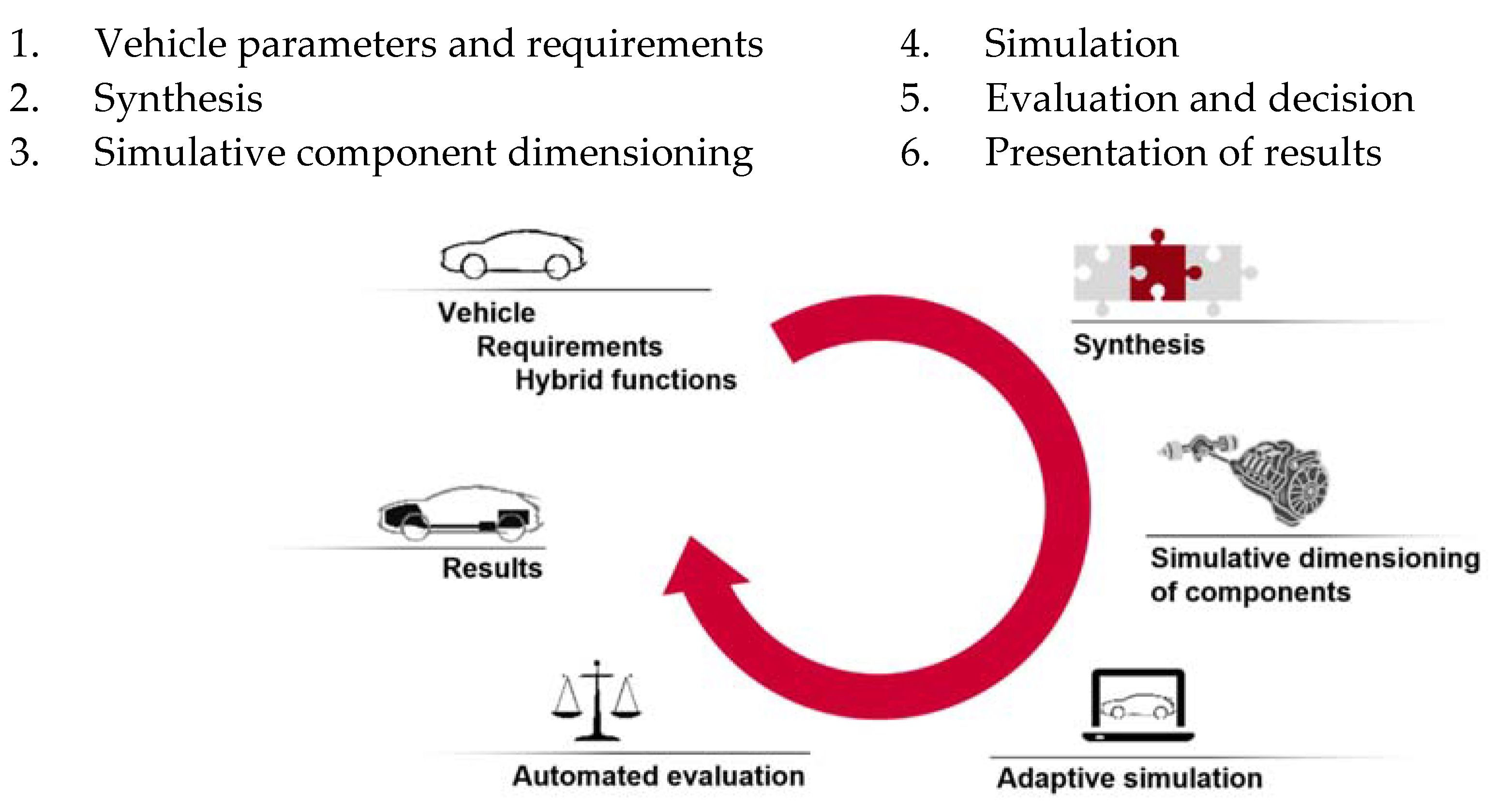
The methodology for the design concept for powertrains is developed incrementally and consists of individual sub-projects. Each of those sub-projects represents a working step for the identification, design and evaluation of new electrified powertrains. Overall, the requirements-mask and four computer tools are implemented in a virtual development chain (
Figure 1).
The steps for conceptualizing and evaluating electrified powertrains are based on three input parameters. First, there are the vehicle parameters, such as vehicle mass without powertrain [
18] or the c
d value. Then, road performance requirements for the powertrain and efficiency requirements for the hybrid functions were deduced. Alongside the requirements and demands from statutory cycles, such as the New European Driving Cycle (NEDC) and Worldwide harmonized Light vehicles Test Cycle (WLTC), requirements from direct customer operation were analyzed and integrated using the 3D methodology from the Institute of Automotive Engineering (IAE) [
17].
Based on the requirements and functions, a synthesis was implemented in the virtual development chain as the first calculation tool. This makes it possible to generate all the possible powertrains from a list of powertrain components. This list of components can be extended or reduced in line with the dynamic development of concept-influencing components.
To identify the most suitable powertrain for each set of requirements, the key is to consider and evaluate the entire solution space for possible powertrains. Computer-aided synthesis makes it possible to analyze a comprehensive range of possible powertrains and to validate them according to fundamental functionality [
19].
The most important powertrain components must be dimensioned for the simulation, evaluation, and optimization of various hybrid powertrains. These include all of the installed energy converters and stores. Their design reflects the requirements that were previously described and the hybrid functions to be realized. A key component of hybridized powertrains is the combustion engine. Unlike conventional powertrains, in a hybrid arrangement the power output of the combustion engine need not necessarily equate to the total propulsive power required. The operating range of the combustion engine and its required rated output are strongly influenced by the powertrain architecture and the degree of electrification. Various different engine versions are derived from one base unit. Distinctions are made between combustion engines according to engine supercharging, variability of the valvetrain, and the compression ratio. Thus, a range of specific outputs from 40 to over 90 kW/L can be achieved [
20].
Following dimensioning of the key components, the parameterized vehicle can be simulated with each of the designed powertrains. A modular longitudinal dynamics simulation environment for road performance and consumption can be used for this purpose. When combined with the cost and dimensioning models, all relevant criteria for subsequent evaluation are deduced, simulated, and logged with data for each topology investigated [
21].
Using the simulation data, it is possible to compare the different topologies with each other. To that end, they are evaluated using weighted criteria, arranged on an evaluation scale and sorted in order of best fulfillment. For different requirements, vehicle segments, or core markets, the most promising powertrain topologies can be defined and evaluated.
The key outcome of the virtual development chain is a variant-based powertrain design approach. The program determines a selection of different powertrains that have been designed for the respective core markets or for defined technical functionalities in line with the prevailing customer requirements.
2.2. Vehicle Parameters and Requirements
Requirements are the basis for every development project and define what customers, developers, and the company expect of a potential new product. They constitute the benchmark for solution-finding and the basis for the evaluation of solutions. To that end, all of the necessary requirements are captured at the start of a development project, using the data available. These are then adapted, firmed up, and expanded throughout the entire development process. Finally, reference is made to the data obtained in this way when evaluating the solution options generated. However, the requirements for a development project may be diverse and potentially lead to conflicting objectives.
In automotive powertrain development, the requirements are determined from the desired or required characteristics and functions of the powertrain. They are not based exclusively on customer preferences and manufacturer specifications; for individual transport they must also take account of society and legislation. This project places the focus on road-performance-specific criteria, the manufacturing costs of the powertrain, environmental compatibility based on emissions, as well as customers’ mobility requirements and habits.
The requirements can fundamentally be divided into three categories. The first category comprises the requirements of customers and society. The second category can be deduced from operating limit requirements. A third area constitutes the statutory and dynamic requirements in the form of design approval cycles (cf. [
21]).
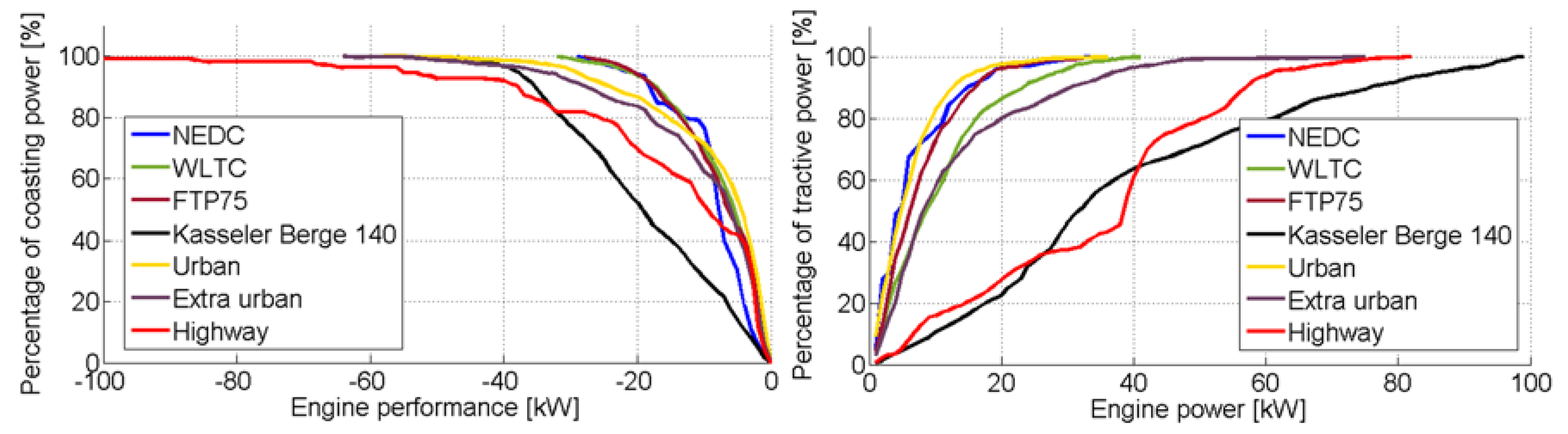
One example of dynamic requirements in the form of cycles is the tractive power.
Figure 2 on the right shows the tractive power that is needed to drive through various design approval cycles with a midsize vehicle. The more efficient the powertrain, the higher its corresponding power units output. For example, if a near-wheel electric motor supplies 20 kW to the axle, that power is already sufficient to cover more than 80% of most cycles purely electrically. With 40 kW of tractive power, even more dynamic cycles, such as the WLTC or an extra urban cycle, can be almost completed. Only high dynamic requirements that occur on freeways or a mountainous road cycle, like “Kasseler Berge” at a constant 140 km/h, demand more tractive power.
A similar assessment can be deduced for the technical requirements and limit values for recuperation—energy recovery through regenerative braking. Hybrid vehicles offer the possibility to convert the kinetic energy that is converted into heat by the brake disks on a conventional vehicle into electrical energy with the electric motor in alternator mode. Depending on the hybrid drive, its corresponding efficiency and the type of the brake system, the output at the power unit may be lower. In
Figure 2 on the left, with a near-wheel alternator output of 20 kW, approx. 80% of the theoretically recoverable energy can be used in most of the design approval cycles. The high speeds on freeways and consequently the high braking performances call for a higher alternator output. A balance needs to be struck between the maximum possible regenerative deceleration, the charging power at the battery, and the additional costs.
2.3. Synthesis
The automated synthesis of new powertrain topologies to accommodate shifting framework conditions has so far concentrated on a stringent and undivided energy flow, on individual components of the powertrain, or on parameter variation (cf. e.g., [
22,
23,
24]). A system analysis of parallel or ramified energy flows, such as those that are predominantly used in hybrid powertrain systems can therefore only be realized inadequately.
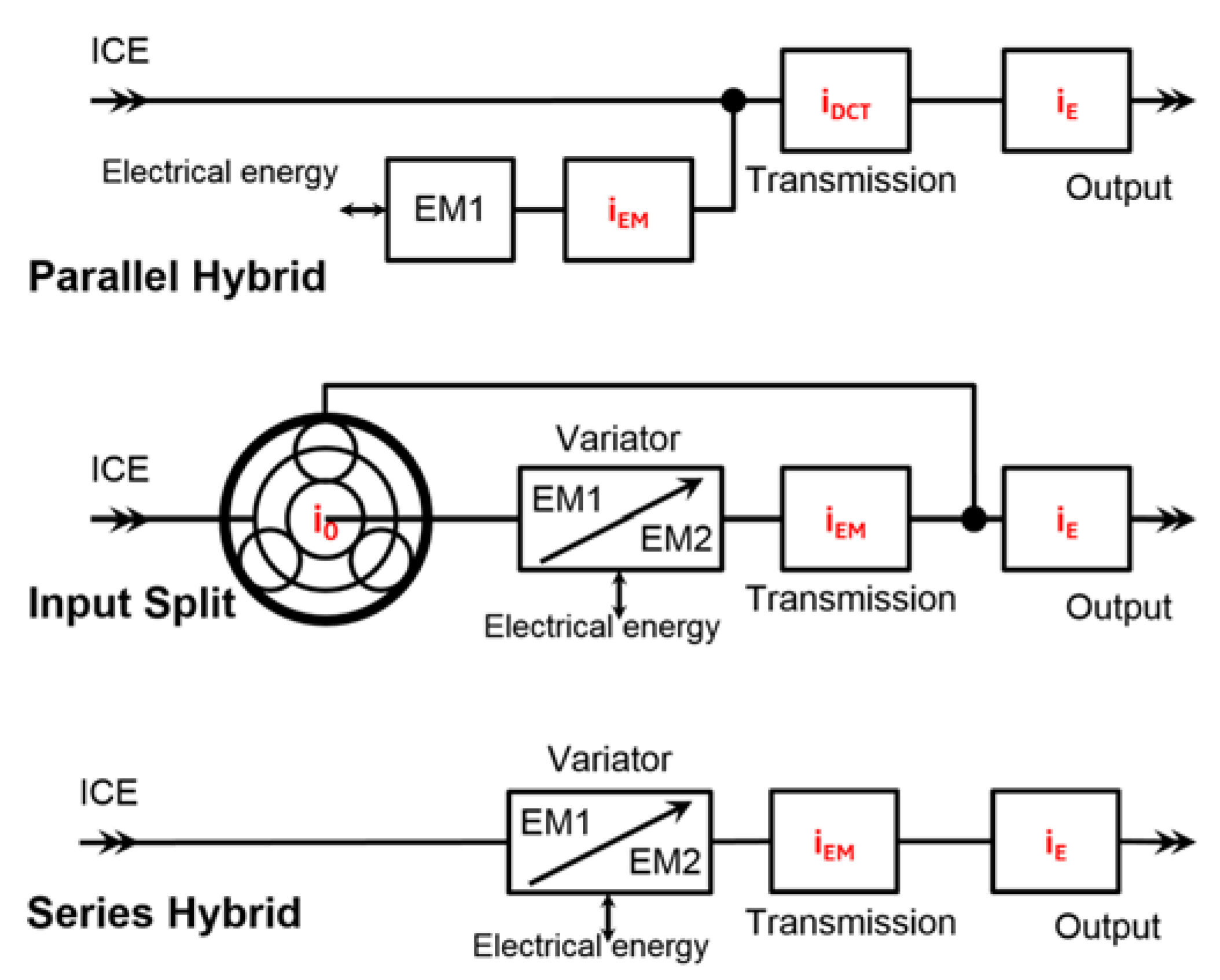
To enable the realization of an automated synthesis of electrified powertrains, first the “electrified powertrain” system under consideration and its limits are defined according to the state of the art and all synthesis-related powertrain components and assemblies are determined. The corresponding powertrain components, their characteristics, and functionalities, as well as their technology parameters and characteristic values are assigned to the components. Each component is logged in a list of components with its “linking-related” parameters—inputs and outputs. Hybrid powertrain structures can be analyzed and synthesized systematically and automatically by varying the number and arrangement of these basic elements. One such example is the arbitrary positioning and variation of transmissions and transmission ratios in various different powertrain topologies in order to investigate the effects on the ratio of efficiency to costs (
Figure 3).
The components for this are regarded as black boxes and they are reduced to their input and output. Two components are then combined if the output parameters (such as engine speed and torque interval) of one component are compatible with the corresponding input parameters of the other component.
Based on their respective compatibility, different components are linked to each other. Each possible linking is saved as a new solution variant and serves as the starting point for the next step in synthesis. This process is continued until all of the link paths have reached a source, in other words, a tank or a battery. Each link path that extends from the driven wheels to a source thus constitutes a solution, in other words, a possible powertrain topology.
So that ramifying and converging power paths can be realized, input-split elements and node elements must additionally be defined in the list of components. A node element may be a shaft that is driven both by the combustion engine and by an electric motor. For the split element, as well as the classic planetary gear train, access e.g., by several electrical components (such as electric motors) to one component (e.g., battery) simultaneously must be approved and defined. The linking of the components results in hybrid forms as well as in series, parallel, and input-split powertrain topologies (cf.
Figure 3 and [
19]).
2.4. Simulative Dimensioning of Components
A key component of hybridized powertrains is the combustion engine. Unlike conventional powertrains, in a hybrid arrangement the power output of the combustion engine need not necessarily equate to the total propulsive power that is required. The operating range of the combustion engine and its required rated output are strongly influenced by the powertrain architecture and the degree of electrification [
20]. To meet package-specific requirements, it is shown in the following how a large number of engine versions can be derived from one base unit. The base unit takes the form of a gasoline engine with a displacement of 2000 cm
3 and four cylinders. A distinction is made between the combustion engines that are investigated according to engine turbocharging, variability of the valvetrain, and the compression ratio. Thus, a range of specific outputs from 40 to over 90 kW/L can be achieved. The versions were assembled and simulated by means of one-dimensional CFD-simulation (computational fluid dynamics simulation). FKFS UserCylinder was used for predictive simulation of the combustion process with modified engine parameters. In combination with a knock model, statements over fuel consumption were made possible.
The derived engine versions were selected with the aim of evaluating the influence of measures to reduce partial-load consumption or to improve transient response in hybridized use. In addition to cost savings from the absence of actuators or turbocharging units (with intercooling), a reduction in application costs can also be achieved. For this concept study the engine operation modes “catalyst heating” and “engine heat-up” were not investigated.
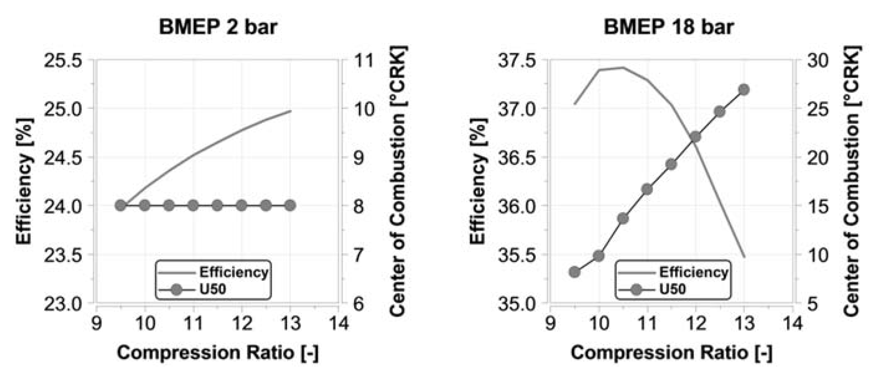
2.4.1. Influence of Compression Ratio
The influence of the compression ratio on the efficiency of the ideal Otto combustion cycle is described while using the following formula:
Thus, the higher the compression ratio, the higher the thermal efficiency. However the compression ratio cannot be increased indefinitely in the gasoline engine. Because of the increased pressure and temperature level in the combustion chamber at high compression ratios, undesirable auto-ignition in the air/fuel mixture can occur. This phenomenon is referred to as knock. To avoid knock, the ignition timing can be adjusted. Retarding the ignition timing means that the bulk of heat release by the combustion process occurs after TDC. The prevailing pressure level is reduced because the piston is now already moving downward and the auto-ignition of the mixture can be avoided. However, changing the ignition timing also shifts the center of combustion, leading to reduced efficiency.
Figure 4 shows the influence of the compression ratio on the efficiency of the gasoline engine. For the load point shown with an effective mean pressure of 2 bar, it can be seen that efficiency rises along with compression ratio and a constant center of combustion. When operating with an effective mean pressure of 18 bar, it can be observed that the higher the compression ratio is, the more the center of combustion is retarded. This is the result of the changed ignition timing to prevent knock. Efficiency thus falls, despite the increased compression ratio.
The choice of compression ratio depends very much on the desired specific output for the engine. For the subsequent investigations, compression ratios of 11.7 and 13 were used for the naturally aspirated engine variants, and these values were set at 11.7 and 9.6 for the turbocharged ones.
2.4.2. Influence of Valvetrain Variability
The gasoline engine’s operating process can be strongly influenced by the valve timing. Specifically, when operating at partial load, the amount of residual gas in the cylinder can be varied by valve opening overlap at the intake and exhaust ends.
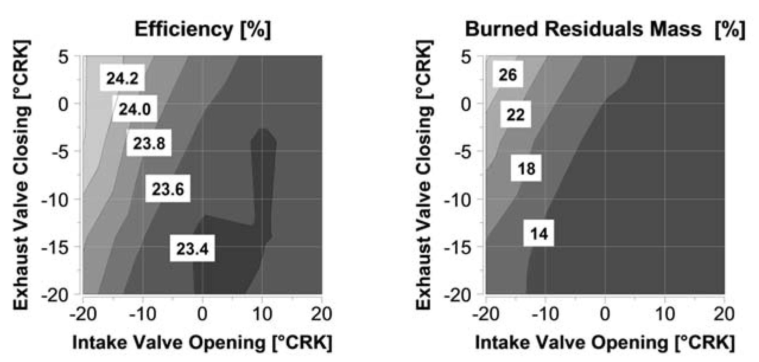
Figure 5 shows the valve timing set for a partial-load operating point at 2000 rpm with a mean effective pressure of 2 bar.
Figure 5 shows on the left side the efficiency of the engine for different cam timings. The valve overlap of the intake and the exhaust valves (IV and EV), for 1 mm valve lift, can be set from +25 °CRK to −40 °CRK. These valve timing settings can be realized by means of cam phasers (CP).
The high valve overlap can produce an internal residual gas level of up to 26%, whereas in the negative valve overlap, the residual gas level reaches only around 14%. The high residual gas level is attributable to the highly negative pressure gradient between the intake and exhaust side. Along with a rising residual gas level, the maximum temperature of combustion falls, and consequently, the thermal losses through the combustion chamber walls. In addition, with rising residual gas levels there must also be a rise in the pressure level at the intake end to ensure adequate cylinder filling with fresh air/fuel mixture. This leads to reduced gas exchange losses. The range of effective efficiency due to cam phasing in this operating point is between 23.4% and 24.2%.
Another means of influencing the gas exchange is to use valve lift adjustment. This permits switching between several different camshaft contours. For the subsequent investigations, valve lift adjustment at the intake end was used for the versions with specific outputs of less than 75 kW/L. Lift adjustment (LA) at the exhaust end was used for the versions with higher specific outputs. At the intake end, either very long (Atkinson) or very short (Miller) valve opening periods can be realized to achieve de-throttling. At the exhaust end, on the other hand, flow separation of the exhaust pulses can be achieved with opening periods of less than 180 °CRK in order to ensure that the exhaust gas flowing out of the cylinders are not adversely influenced.
2.4.3. Influence of Turbocharger
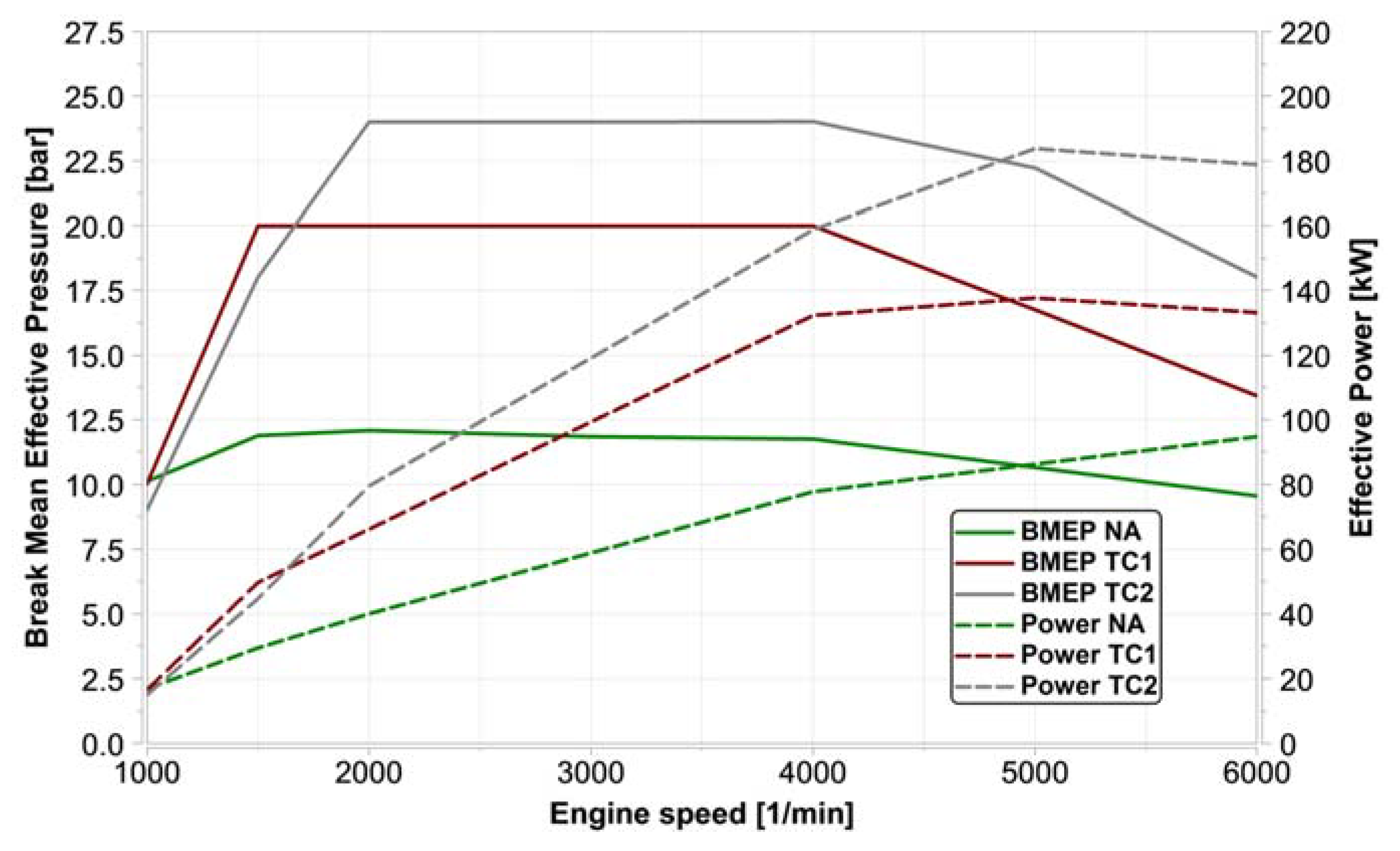
Various supercharging systems are used to vary the specific engine output. A distinction is made here between normally aspirated (NA) and turbocharged (TC) systems. No additional charging unit is used for naturally aspirated engines. The rated output therefore depends on the maximum air flow rate and the rated speed. The versions with specific outputs greater than 50 kW/L use turbocharging. In the turbocharger, the exhaust gas flow drives a turbine, which in turn drives a mechanically connected compressor that increases the density of the air that is drawn in. This increased air density at the intake end means more oxygen is available for the combustion process. The resulting increase in the amount of fuel permits increased performance from the same displacement, see
Figure 6. Two turbochargers are used for the investigation presented. These differ in respect of the geometrical dimensions of the turbine and compressor, resulting in a change in the maximum air mass flow rate.
2.5. Adaptive Simulation
The synthesis creates a large number of powertrains that are simulated in a subsequent step. Automated transfer of the synthesis data to the simulation model is a basic requirement. This automatism on the one hand brings a relatively large time saving, because it is not necessary to create a new model for every synthesized topology. On the other hand, the virtual development chain can also be applied in simulation by development engineers who do not possess prior knowledge.
A components library forms the basis of adaptive simulation. All of the possible assemblies, components or units of a powertrain are stored there in the form of finished “building blocks”. For the combustion engine, they comprise the efficiency maps that are described above. The same applies to the various types of electric motors. Depending on application, finished transmissions with corresponding gearshift maps or individual transmission speeds with scalable parameters can be saved. The gearshift maps or parameters can be adapted based on the necessary spread, derived from the slip limit and the maximum speed, as well as the efficiency map of the combustion engine.
Based on the synthesis data, the adaptive simulation entirely automatically generates a MATLAB Simulink model of the current powertrain topology. Only the elements that are currently required are loaded from the components library for that purpose. The totality of the activated components constitutes the power flow of the topologies generated. The corresponding components are dimensioned via parameters and the model for the subsequent simulation is saved. This process is repeated until all topologies generated by synthesis have been considered.
Subsequently, three different topologies with the same electric power but with different ICE variants and a variation of power were simulated.
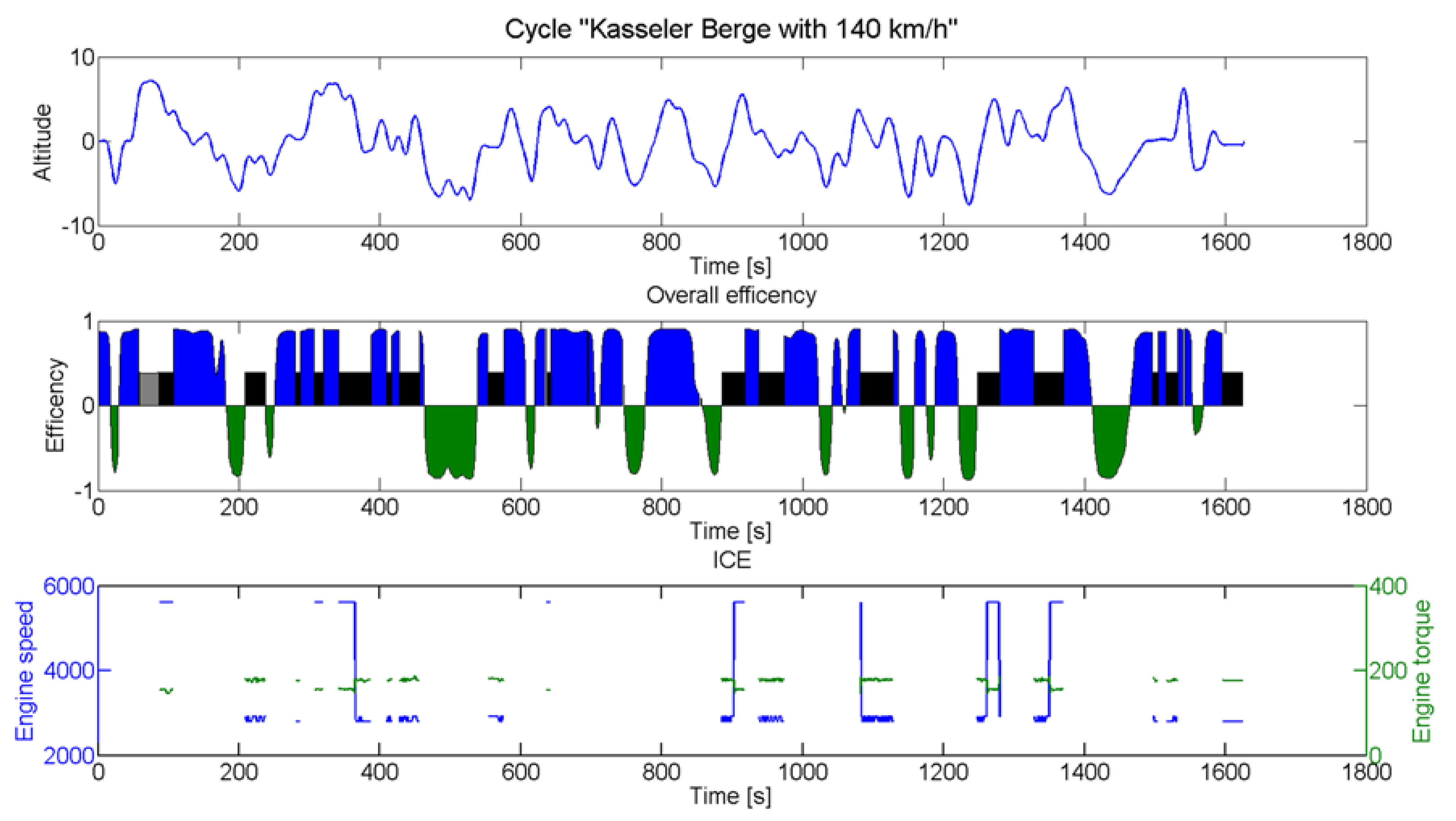
Figure 7 displays the simulation results for a power-split hybrid powertrain with a naturally aspired engine with 95 kW. The top plot shows the elevation profile of the “Kasseler Berge” cycle. The constant vehicle speed over the complete cycle is 140 km/h. This cycle can be used to determine the requirements for hybrid powertrains. Due to the high vehicle speed the power output of the powertrain is in a high range. In addition, the elevation profile leads to high recuperation potentials. The cycle is driven SoC-neutrally, in other words, the charge level of the battery after driving the cycle is the same as before driving the cycle. The middle segment of
Figure 7 shows the efficiency of the powertrain components. The blue and green areas display the efficiencies of the electric machine for motor (blue) and generator (green) operation. The efficiency of the combustion engine is shown in (black) for hybrid mode and (grey) for the combustion engine only.
The third plot in
Figure 7 displays the resulting speeds and torques of the combustion engine in hybrid mode (black areas). For the periods where the combustion engine is running, the hybrid control unit sets the operating point to a complete de-throttled area to ensure high efficiencies. To meet high power demands, the engine is also set to its peak power at around 6000 rpm.
2.6. Automated Evaluation
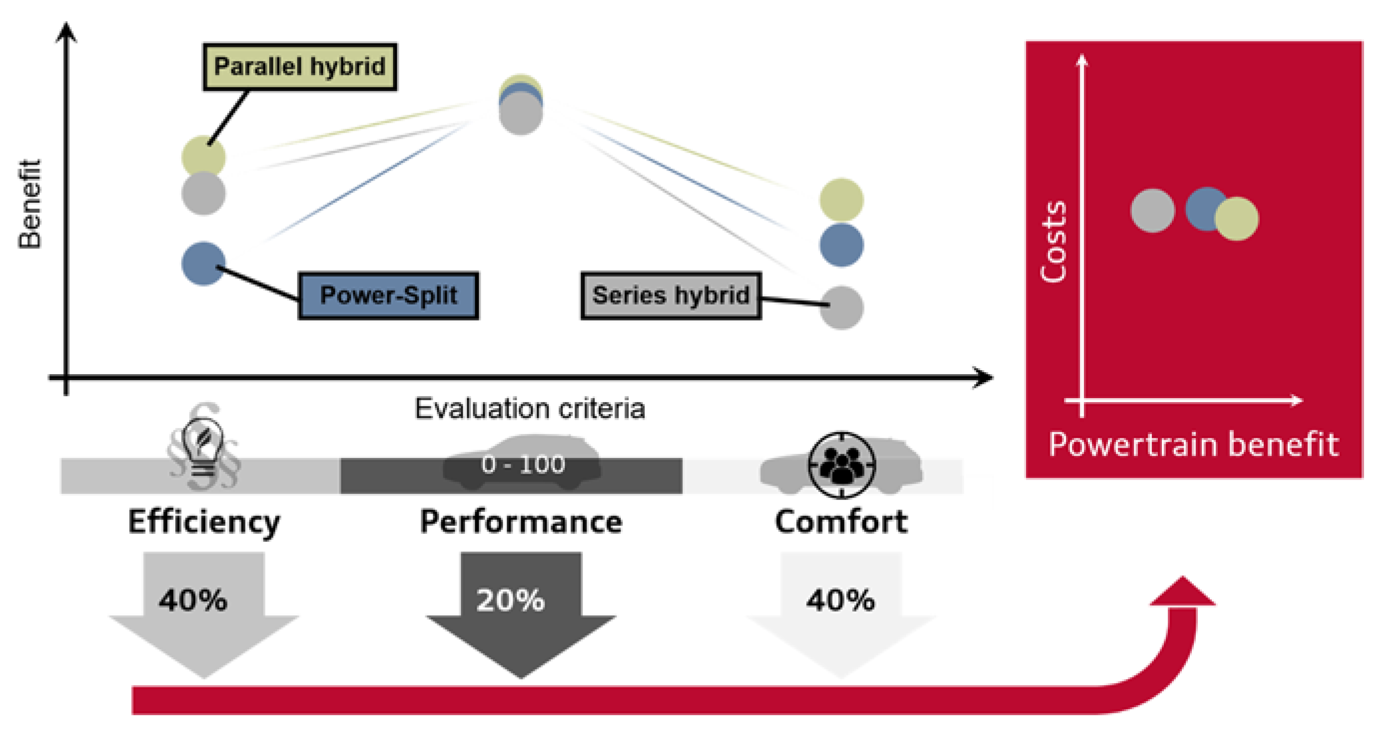
The objective in evaluating the powertrain is a swift and easy evaluation of the characteristics of new powertrain topologies. For a finite quantity of solutions with the same information content, common evaluation criteria need to be defined. As well as the criteria cluster of efficiency, road performance, and costs, the powertrains’ comfort is evaluated.
Uniformly classifiable and comparable values or ratings are applied to the evaluation criteria. This weighting of the criteria can be carried out for specific markets and based on expert knowledge (
Figure 8). For all of the versions considered, all the ratings are then totaled. The highest figure accordingly represents the best solution and the lowest figure the poorest solution. This ranks the solutions in order, reflecting the so-called degree of fulfillment. The outcome is a robust concept decision for the powertrain being sought. The selected powertrain is the one that best meets the requirements and customer preferences.
The evaluation process is demonstrated by a brief example.
Table 1 shows the simulated fuel consumptions for the three different hybrid architectures with three different combustion engines. For the power-split powertrain the natural aspired engine shows an average consumption of 8.77 L/100 km during conventional and hybrid operating phases (R). The consumption for the whole cycle, including electric driving phases, is 5.95 L/100 km (C).
The overall results for the cycle “Kasseler Berge 140 km/h” with the investigated vehicle show the lowest fuel consumption for a parallel-hybrid with a moderate turbocharged engine. The introduced approach can be used for further investigations, especially for urban driving cycles.
The simulated results from
Table 1 are graded according to their values under the tab “Efficiency” in
Figure 8. A lower consumption is better evaluated and is seen higher in the diagram, while high consumption is placed deeper.
The same procedure is repeated for the “Comfort” tab. Through the integration of comfort potential, solutions with technically and economically good ratings that only allow for acceptable customer comfort based on high application and coordination cost are to be avoided [
21]. Here, the ratio of ICE speed and vehicle speed is evaluated as an example. The vehicle speed is the same for all engine and topology combinations over the cycle: 140 km/h. The highest average ICM speed shows the series hybrid with about 4000 rpm, and therefore gets the lowest grade. Power split and parallel hybrids have a lower and therefore more comfortable engine speed profile.
Under “Performance”, for example, the system grades whether the vehicle can travel through the cycle with or without electrical assistance. This is possible for all engine topology variations except for the 95 kW aggregate.
Finally, the powertrain benefit is compared with the powertrain costs (
Figure 8 on the right). Therefore, the component and powertrain cost are based on cost models. Unless otherwise indicated, the cost information refers to the entire component, i.e., to the system level. The structure of cost models for energy converters and storage is always the same in principle. It consists of the specific costs in relation to the parameter defining the component, e.g., the battery costs with the battery parameter kWh. In addition, a distinction must also be made between battery systems for hybrid electric vehicle (HEV), plug-in hybrid electric vehicles (PHEV), and battery electric vehicles (BEV). Therefore, in the context of this work the prices listed in
Table 2 have been used.
In this example scenario, the parallel hybrid with the 130 kW ICE would be the recommended powertrain configuration.
3. Conclusions
In this article, a tool chain for the simulation, dimensioning, and evaluation of electrified drivetrains was introduced. Within these computer-assisted tools, all of the necessary development steps for concept identification are combined in an adaptive simulation environment. The tool chain aids the development process and shortens the development lead times.
The program structure is modular, so a wide range of development questions can be scientifically investigated and answered in a short time without additional effort. Notable among these are, for example, fleet sensitivities of different powertrains, the integration of new electrified powertrains into existing portfolios, or an analysis of the effects and potential of innovative technologies.
Three of the fundamental tools, the synthesis, the powertrain dimensioning, and the automated evaluation, were described. The synthesis tool allows for the generation of different powertrains, ranging from simple topologies, like parallel hybrids, up to complex topologies with multiple power split elements. In order to simulate the powertrains in different cycles, the main components have to be dimensioned. The powertrains have to reach the different requirements, as well as to ensure the functions and effectiveness of the different hybrid functions. The dimensioning of the powertrains is automated to enable the examination of a plurality of powertrains generated by the synthesis. Subsequently these powertrains are evaluated on the basis of efficiency and economy criteria. The powertrains with the greatest potentials are then selected and can be transferred to detailed development, further optimization, and analyses.
The outcome of the overall tool chain is a robust concept for future powertrains. The selected drive system has been optimized in line with market-specific requirements and customers’ wishes. This methodical and reproducible approach enables to identify future powertrain concepts that are based on the synthesis of innovative, electrified drive systems, and their evaluation in customer driving use.


