Article

Control of Permanent Magnet Synchronous Motor Based on Adaptive Super-Twisting Sliding Mode Observer and Improved PSO

Vocational and Technical College, Hebei Normal University, Shijiazhuang 050024, China
*
Author to whom correspondence should be addressed.
World Electr. Veh. J. 2026, 17(9), 446; https://doi.org/10.3390/wevj17090446
Submission received: 18 July 2026 / Revised: 12 August 2026 / Accepted: 24 August 2026 / Published: 27 August 2026
(This article belongs to the Section Propulsion Systems and Components)

Abstract

To mitigate the chattering and limited adaptability of conventional sliding mode observers (SMOs) in position sensorless control for permanent magnet synchronous motors (PMSMs) across a wide range of operating conditions, a control strategy based on an adaptive-gain super-twisting sliding mode observer (AST-SMO) combined with improved particle swarm optimization (PSO) for speed loop PI parameter tuning is proposed. The observer incorporates a time-varying gain function, which is driven by the magnitude of the current observation error and governed by an integral-type adaptive law. This replaces the fixed-gain structure that necessitates a predetermined disturbance upper bound, thereby effectively suppressing chattering and ensuring high estimation accuracy across a wide speed range and under abrupt load changes. For speed loop control, an improved PSO algorithm with cooperative adjustment of learning factors and inertia weight is introduced for offline optimization of PI parameters, further enhancing dynamic response and anti-disturbance capability. Simulation and experimental results demonstrate that, compared with the traditional ST-SMO and LST-SMO, the proposed AST-SMO yields lower rotor position estimation errors and reduced speed fluctuations under both steady-state and transient conditions. Meanwhile, the PSO-optimized PI controller significantly shortens settling time and reduces overshoot. The proposed strategy features a simple structure and is suitable for engineering implementation.

1. Introduction

The sliding mode observer (SMO), as a nonlinear state estimation approach based on sliding mode variable structure theory, has been widely applied in the position sensorless control of permanent magnet synchronous motors (PMSM). Its core idea is to design a sliding surface using the motor mathematical model and estimate the rotor position and speed by utilizing the switching function of the back electromotive force (back-EMF) signal and the current error. The SMO offers advantages such as a simple structure, strong parameter robustness, and fast dynamic response. However, a key problem with traditional SMO lies in the chattering phenomenon, which has long been a research focus for scholars worldwide [1,2]. To address this issue, a low-pass filter (LPF) was introduced in [3] to filter the back-EMF, thereby reducing the chattering caused by the inherent defects of the SMO.
In [4], a full-order SMO with synchronous frequency tracking (SFT) filtering was proposed for interior permanent magnet synchronous motor (IPMSM) sensorless control, which avoids phase delay and harmonics, and employs Luenberger-based speed estimation with experimental validation. A second-order lead compensation quadrature phase-locked loop (SOLC-Q-PLL) was presented in [5] to suppress sixth-order position harmonics in IPMSM sensorless control without causing phase delay or bandwidth loss. In [6], an adaptive LPF combined with an orthogonal phase-locked loop (PLL) was proposed to reduce estimated harmonic errors. This method adaptively compensates for harmonics in the back-EMF estimation to eliminate the corresponding position estimation errors. However, the incorporation of an LPF inevitably introduces phase lag and increases system complexity.
The super-twisting sliding mode observer (ST-SMO), as a representative of second-order sliding mode algorithms, significantly attenuates chattering at the mechanism level by introducing a continuous switching term and a double integral structure, becoming a research hotspot in recent years. The super-twisting algorithm (STA) is widely used in observers and controllers due to its chattering-free characteristics [7]. In [8], a permanent magnet linear synchronous motor (PMLSM) sensorless control system with continuous terminal sliding mode control (CT-SMC) for fast finite-time tracking and a fuzzy adaptive gain ST-SMO (F-ST-SMO) for chattering reduction was proposed and validated by both simulation and experiment. In [9], an adaptive SMO was proposed, in which the switching gain can be adaptively adjusted according to the actual operating conditions. To reduce the chattering problem and simplify the control system, sensorless control of PMSM based on ST-SMO was adopted in [10]. However, the traditional STA employs fixed sliding mode coefficients, making the control system unsuitable for wide speed ranges. The ST-SMO with constant sliding mode coefficients cannot maintain its good performance under different operating conditions, exhibiting poor robustness. Many scholars have proposed combining various adaptive algorithms with ST-SMO to improve controller performance. A novel speed exponential function adaptive estimation was proposed in [11] to solve the chattering problem, combined with a quadrature signal generator based on a second-order generalized integrator (SOGI) to filter the back-EMF. In [12], an elliptical saturation function was designed to construct an improved ST-SMO, and its finite-time convergence was analyzed. A continuous sigmoid function was used as the switching function in [13] and combined with fuzzy control theory to adaptively adjust the sliding mode gain. A STA-based back-EMF observer was proposed in [14] to achieve reduced chattering, better estimation accuracy, and faster convergence.
In recent years, various online parameter identification and rectification methods have been developed to enhance the control performance of PMSM drives under parameter variations. For instance, an alternating dual-Adaline observer network for SPMSMs under i d = 0 control was proposed in [15]. It addresses the rank-deficiency problem by exploiting the slow temperature-dependent dynamics of stator resistance and rotor flux linkage, achieving high-precision identification without signal injection while simultaneously compensating for inverter nonlinearity. Within the framework of model predictive control, an online parameter rectification strategy was developed in [16] based on objective-constrained optimization to correct stator inductance and rotor flux linkage in real time, combined with a reduced-order extended Kalman filter for sensorless operation. The above studies demonstrate that online parameter identification and rectification are effective means to enhance parameter robustness in sensorless control systems. The AST-SMO proposed in this paper achieves automatic compensation for parameter perturbations through its integral-type adaptive gain law, without requiring explicit online parameter identification.
Although adaptive-gain super-twisting sliding mode observers have been investigated in the existing literature, most reported schemes employ either linear gain adjustment laws [12] or fuzzy-logic-based gain schedulers [8]. These approaches rely on static mappings of instantaneous errors and generally require a priori knowledge of the disturbance upper bound to guarantee stability. In contrast, the contribution of this paper lies in proposing an integral-type nonlinear adaptive law k ˙ = ρ i ~ s . This mechanism fundamentally differs from prior arts in three aspects: (1) the gain k t evolves based on the historical accumulation of the current observation error rather than its instantaneous value, providing superior robustness against abrupt disturbances; (2) it eliminates the tedious procedure of predetermining the disturbance bound Δ , as the gain automatically increases until the sliding condition is satisfied; (3) the number of manually tuned observer parameters is significantly reduced through a decoupled design.
Therefore, this paper proposes a PMSM position sensorless control strategy based on an adaptive-gain super-twisting sliding mode observer (AST-SMO) combined with improved particle swarm optimization (PSO) for speed loop PI parameter tuning. Compared with the traditional fixed-gain ST-SMO, the proposed method has the following advantages: In the observer design, this paper constructs a time-varying gain function using the current observation error magnitude as a variable and its integral-type adaptive law, replacing the fixed-gain structure that requires presetting the disturbance upper bound. This adaptive law can automatically adjust the sliding mode gain according to changes in motor operating conditions, effectively suppressing chattering and maintaining high-precision estimation over a wide speed range and under sudden load changes. For speed loop control, this paper introduces an improved PSO algorithm based on the cooperative improvement of learning factors and inertia weight for offline optimization of PI parameters, further enhancing the system’s dynamic response speed and anti-disturbance capability.
To more clearly reveal the differences and deficiencies among the various ST-SMO improvement strategies discussed above, a qualitative comparison is conducted from four aspects: gain tuning mechanism, requirement of prior knowledge of the disturbance bound, parameter tuning complexity, and robustness, as summarized in Table 1.
As shown in Table 1, both fixed-gain and linear-gain schemes rely on prior knowledge of the disturbance bound and struggle to maintain optimal performance across a wide speed range. The fuzzy adaptive scheme, although not requiring precise modeling, relies heavily on expert experience for parameter tuning. In contrast, the proposed integral-type adaptive-gain ST-SMO requires no prior knowledge of the disturbance bound and features the most streamlined parameter structure, thereby providing a solid theoretical foundation for the subsequent experimental validation.
The remainder of this paper is organized as follows. Section 2 establishes the mathematical model of the PMSM. Section 3 develops a sensorless control strategy based on the ST-SMO and analyzes the inherent limitations of its conventional form. Section 4 presents the structure of the proposed AST-SMO, along with the gain adaptation law and the corresponding Lyapunov-based stability proof. Section 5 details a speed-loop PI tuning strategy using an improved PSO algorithm. Section 6 validates the effectiveness of the proposed scheme through comparative simulations and experimental tests. Finally, Section 7 summarizes the main conclusions.

2. Mathematical Model and Coordinate Transformation of PMSM

To simplify the control system design, it is typically treated as an ideal motor under the following assumptions: (1) iron core saturation is neglected; (2) eddy current and hysteresis losses are disregarded; and (3) the three-phase currents are balanced sinusoidal waveforms. In the three-phase stationary coordinate system, the voltage, flux linkage, and torque equations can be expressed as follows:
u a u b u C = R s 0 0 0 R s 0 0 0 R s i a i b i c + d d t ψ a ψ b ψ c
ψ a ψ b ψ c = L a a M a b M a c M b a L b b M b c M c a M c b L c c i a i b i c + ψ f cos θ e cos ( θ e 2 π / 3 ) cos ( θ e + 2 π / 3 )
T e = 1 2 p n i a b c T L θ m i a b c + p n ψ f i a b c T θ m c o s θ e c o s ( θ e 2 π / 3 ) c o s ( θ e + 2 π / 3 )
The motion equation is
J d ω m d t = T e T L B ω m
where u A , u B , u C are the three-phase winding voltages; i A , i B , i C are the three-phase winding currents; R s is the stator resistance; ψ a , ψ b , ψ c are the stator flux linkages; M a a , etc., are the mutual inductances; L a a , L b b , L c c are the self-inductances; θ e is the electrical angle of the motor, where p n is the number of pole pairs, θ e = p n θ m is the electrical angle, and θ m is the mechanical angle; ψ f represents the permanent magnet flux linkage; J is the moment of inertia; ω m is the mechanical angular velocity; T L is the load torque; and B is the viscous friction coefficient.
The above model exhibits strong coupling characteristics that are not conducive to controller design. The Clarke–Park transformations are introduced to convert the model to the two-phase rotating reference frame.
This paper focuses on a surface-mounted PMSM, thus, L d = L q = L s . The voltage and torque equations in the d-q coordinate system are
u d = R s i d + L s d i d d t ω e L s i q u q = R s i q + L s d i q d t + ω e ( L s i d + ψ f )
T e = 3 2 p n ψ f i q
The electromagnetic torque is only proportional to i q , thus the i d = 0 vector control strategy can be adopted to achieve linear torque regulation. The decoupled model after coordinate transformation has a simple form, providing a foundation for the subsequent SMO design.

3. Position Sensorless Control Based on ST-SMO

3.1. Design of the Traditional SMO

Based on the two-phase stationary coordinate system ( α β ), the PMSM voltage equation is
u α u β = R s i α i β + d d t ψ α ψ β
For a surface-mounted PMSM, the back-EMF can be expressed as
E α E β = ω e ψ f s i n θ e ω e ψ f c o s θ e
Substituting Equation (8) into Equation (7), and considering L d = L q = L s , the current state equation can be obtained:
d d t i α i β = R s L s i α i β + 1 L s u α u β 1 L s E α E β
The SMO is constructed as follows:
d d t i ^ α i ^ β = R s L s i ^ α i ^ β + 1 L s u α u β 1 L s v α v β
where the switching functions are v α = k · s g n ( i ^ α ) , v β = k · s g n ( i ^ β ) . Define the current observation errors: i ~ α = i ^ α i α , i ~ β = i ^ β i β , and k > 0 is the sliding mode gain. Combining Equations (9) and (10), the current error equation is obtained:
d d t i ~ α i ~ β = R s L s i ~ α i ~ β + 1 L s E α E β 1 L s v α v β
Select the sliding mode surface s α = i ~ α , s β = i ~ β . When the state variables reach and stay on the sliding surface, i ~ α = 0 , i ~ β = 0 . According to the equivalent control principle,
E α E β = v α v β e q = k · s g n ( i ~ α ) e q k · s g n ( i ~ β ) e q
The back-EMF information is implicit in the high-frequency switching signal. The discontinuity of the sign function causes severe chattering in the estimation results. Traditional methods employ a low-pass filter (LPF) to extract the continuous back-EMF and then calculate the rotor position θ ^ e and speed ω ^ e via the arctangent function. However, the LPF introduces phase lag, which necessitates additional phase compensation.

3.2. Position Identification Using Phase-Locked Loop (PLL)

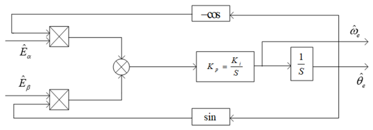
To improve the accuracy of position and speed identification, PLL is used to replace the traditional arctangent function calculation. The PLL consists of a phase detector, a loop filter, and a voltage-controlled oscillator [17,18]. The inputs are the estimated back-EMFs E ^ ˙ α , E ^ ˙ β , and the outputs are the estimated rotor position θ ^ e and speed ω ^ e .
According to the back-EMF expression Equation (8), when the estimation error is small, the position error signal is
Δ θ = E ^ α c o s θ ^ e E ^ β s i n θ ^ e ω e ψ f s i n ( θ e θ ^ e ) ω e ψ f ( θ e θ ^ e )
Defining k e = ω e ψ f , then Δ θ k e ( θ e θ ^ e ) . This error signal passes through a PI regulator to obtain the speed estimate. The transfer function of the PI regulator is G P I ( s ) = K P + K i s . The equivalent transfer function of the PLL is
θ ^ e ( s ) θ e ( s ) = k e ( K P s + K i ) s 2 + k e K P s + k e K i
The closed-loop system can be characterized as a typical second-order system. By reasonably selecting the PI parameters, the PLL can track the actual rotor position quickly and accurately. The implementation principle of rotor position identification based on the PLL is shown in Figure 1.

3.3. ST-SMO Design

To attenuate chattering at the mechanism level while maintaining system robustness, the STA is introduced. Selecting stator currents and back-EMFs as state variables, the system equations can be established from Equation (9):
i ˙ α = R s L s i α + 1 L s u α 1 L s E α E ˙ α = δ α i ˙ β = R s L s i β + 1 L s u β 1 L s E β E ˙ β = δ β
where δ α and δ β are the derivatives of the back-EMFs, considered as bounded disturbance terms, δ α Δ , δ β Δ . Based on the super-twisting algorithm, the ST-SMO is designed as
i ^ ˙ α = R s L s i ^ α + 1 L s u α 1 L s E ^ α + k 1 i ~ α 1 / 2 s g n ( i ^ α ) E ^ ˙ α = k 2 s g n ( i ~ α ) i ^ ˙ β = R s L s i ^ β + 1 L s u β 1 L s E ^ β + k 1 i ~ β 1 / 2 s g n ( i ^ β ) E ^ ˙ β = k 2 s g n ( i ~ β )
where k 1 , k 2 > 0 are the fixed sliding mode gains. Subtracting Equation (15) from Equation (16), the error dynamic equation is
i ~ ˙ α = R s L s i ~ α + 1 L s E ~ α k 1 i ~ α 1 / 2 s g n ( i ^ α ) E ~ ˙ α = k 2 s g n ( i ~ α ) δ α
When the gains satisfy k 2 > Δ and k 1 is sufficiently large, the estimated states converge to the true values within a finite time. The estimated back-EMFs E ^ α , E ^ β are then processed by a PLL to obtain the rotor position and speed:
ω ^ e = E ^ α 2 + E ^ β 2 ψ f , θ ^ e = a r c t a n ( E ^ α E ^ β )
The ST-SMO effectively suppresses chattering, but its fixed gains limit convergence speed. Gain selection requires predetermining the disturbance upper bound Δ . When operating conditions change, robustness and observation accuracy may decrease [19].

4. AST-SMO Design

4.1. AST-SMO Structure and Gain Adaptive Law

To address the limitations of the fixed-gain ST−SMO, this paper proposes an AST−SMO, introducing a time-varying gain function k ( i ~ s ) that varies with the current observation error magnitude. The observer expressions are
i ^ ˙ α = R s L s i ^ α + 1 L s u α 1 L s E ^ α + k 1 i ~ α 1 / 2 s g n ( i ^ α ) + k 2 i ~ α E ^ ˙ α = k 3 s g n ( i ~ α ) + k 4 i ~ α i ^ ˙ β = R s L s i ^ β + 1 L s u β 1 L s E ^ β + k 1 i ~ β 1 / 2 s g n ( i ^ β ) + k 2 i ~ β E ^ ˙ β = k 3 s g n ( i ~ β ) + k 4 i ~ β
where the gain parameters are designed in a form associated with the same time-varying gain function k = k ( i ~ s ) :
k 1 = λ 1 k , k 2 = λ 2 k , k 3 = λ 3 k , k 4 = λ 4 k
where λ 1 , λ 2 , λ 3 , λ 4 > 0 are constant proportional coefficients, and i ~ s = i ~ α 2 + i ~ β 2 is the magnitude of the current observation error. The adaptive law for the time-varying gain function k ( t ) is taken in an integral form:
d k d t = ρ i ~ s
where ρ > 0 is the integral proportional factor, and k ( 0 ) = k 0 > 0 is an arbitrarily small positive initial value, ensuring k ( t ) > 0 always holds. This adaptive law causes the gain to increase automatically as the current error magnitude increases and decrease as the error decreases, achieving adaptive balance.
In contrast to conventional proportional-type gain laws ( k i ~ s ) or fuzzy-logic-based gain schedulers, the proposed integral-type law regulates the gain based on the accumulated history of the estimation error, thus requiring no a priori knowledge of the disturbance bound. Furthermore, the gain naturally reduces as the error diminishes, avoiding unnecessary over-gain and preserving the chattering-suppression property of the super-twisting algorithm.

4.2. Error Dynamic Equation

Combining Equations (19) and (15), the error dynamic equation of the AST-SMO is obtained:
i ~ ˙ α = R s L s i ~ α + 1 L s E ~ α λ 1 k i ~ α 1 / 2 s g n ( i ^ α ) λ 2 k i ~ α E ~ ˙ α = λ 3 k s g n ( i ~ α ) λ 4 k i ~ α δ α
Under the condition that the back-EMF derivatives are bounded ( δ α , δ β Δ ), if the time-varying gain function grows through adaptive law Equation (21) and satisfies
k ( t ) > Δ λ 3 ,
then the error vector i ~ α E ~ α T will converge to zero within a finite time. The back-EMF estimates are directly taken from the observer states E ^ α , E ^ β , and after PLL processing, the rotor position θ ^ e and speed ω ^ e are obtained.
The AST-SMO reduces the multiple fixed gain parameters that require repeated tuning to a single adaptive gain k ( t ) and four proportional coefficients, significantly reducing the complexity of parameter design.

4.3. Stability Proof

To verify the stability of the proposed AST−SMO, the Lyapunov direct method is used for proof. Taking the α -axis as an example, consider the error dynamic equation Equation (22) and define the state vector.
σ = i ~ α 1 / 2 s g n ( i ~ α ) E ~ α P = p 11 p 12 p 21 p 22 > 0
Construct a positive definite matrix P. Select the Lyapunov function V = σ T Q σ , where Q is a positive definite matrix. Taking the derivative of V and substituting the error dynamic equation yields
V ˙ = V ˙ α + V ˙ β
where V ˙ a originates from the change in the time-varying gain k ( i ~ s ) . By substituting the adaptive law d k / d t = ρ i ~ s and the property of the gain upper bound, it can be proven that there exists a positive definite matrix M such that
V ˙ a σ T M σ 0
The component V ˙ b originates from the change in the system state and can be expressed as
V ˙ b = 1 i ~ α 1 / 2 σ T X 1 σ σ T X 2 σ + Δ 1 + Δ 2
where matrices X 1 and X 2 are given by
X 1 = λ 1 2 2 λ 3 k + λ 1 2 λ 1 λ 1 1 , X 2 = λ 2 k 2 λ 3 k + λ 1 2 λ 1 λ 1 1
According to Sylvester’s criterion, for X 1 and X 2 to be positive definite, it is sufficient that the leading principal minors are positive:
2 λ 3 k + λ 1 2 > 0 , 2 λ 3 k + λ 1 2 λ 1 2 = 2 λ 3 k > 0
which are satisfied when k t > 0 . In addition, to suppress the disturbance terms Δ 1 and Δ 2 , the gain must be sufficiently large such that k t > Δ / λ 3 . Under this condition, both X 1 and X 2 are positive definite, and the influence of Δ 1 + Δ 2 is bounded by the negative definite terms; thus, V ˙ β 0 is guaranteed.
Consequently, when k ( t ) > / λ 3 , both X 1 and X 2 are positive definite, ensuring that the disturbance terms Δ 1 + Δ 2 are bounded by the negative definite terms, which leads to V ˙ b 0 . According to Lyapunov stability theory, the error states converge to zero within a finite time, and the observer is asymptotically stable. The convergence of the β-axis error can be proven analogously.

4.4. Simulation Verification and Comparative Analysis

To verify the effectiveness of the designed AST−SMO, simulation systems of the traditional ST−MO, LST−SMO (Linear-gain Super-Twisting Algorithm based Sliding-Mode Observer), and AST−SMO were built on the MATLAB/Simulink 2023b platform for comparison.
(1) Sinusoidal trajectory tracking
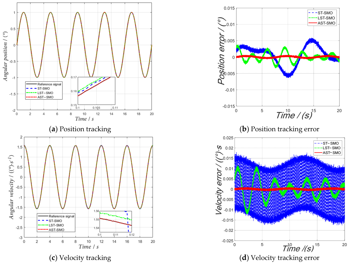
To evaluate the position and velocity tracking performance of the proposed control scheme in the presence of friction nonlinearities and low-frequency disturbances, a sinusoidal reference trajectory is employed for a simulation duration of 20 s. The tracking performance and error comparisons for both position and velocity are illustrated in Figure 2. In Figure 2a and Figure 2c, the black solid line represents the reference position and velocity, respectively. As shown in Figure 2a and its magnified view and Figure 2b, AST−SMO achieves the fastest convergence and maintains a very small position error, whereas ST−SMO exhibits a persistent low-frequency oscillatory error, with LST−SMO showing intermediate performance. For velocity tracking in Figure 2c,d, ST−SMO suffers from severe high-frequency chattering. Although LST−SMO reduces this chattering, it retains a decaying steady-state oscillation. In contrast, AST−SMO significantly suppresses chattering while maintaining minimal velocity errors. The proposed AST−SMO demonstrates improved comprehensive tracking performance compared to the other two schemes.
(2) Parameter robustness verification
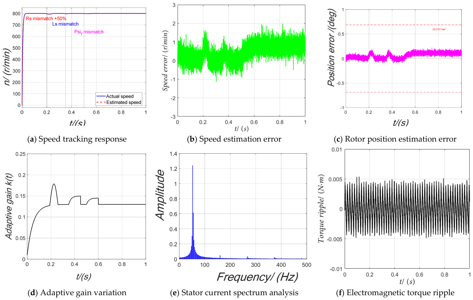
To further assess the robustness of the proposed AST−SMO against parameter uncertainties, simulations were conducted by introducing abrupt changes in stator resistance, stator inductance ( L s ), and permanent-magnet flux linkage ( ψ f ) at 0.2 s, 0.35 s, and 0.5 s, respectively. The performance evaluation of AST−SMO under parameter mismatches is shown in Figure 3.
As shown in Figure 3, the speed estimation error is strictly bounded within ± 2.5 r/min across all parameter mismatch scenarios. Despite transient disturbances at the moment of mismatch, the estimated speed quickly tracks the actual speed. The rotor position estimation error remains within ± 0.012 rad. The adaptive gain k t exhibits smooth integral peaks at the instants of parameter mismatches, indicating that the proposed integral-type adaptive law automatically accumulates error to compensate for the model uncertainties. The FFT analysis of the steady-state stator current shows a total harmonic distortion (THD) of approximately 2.5%. The electromagnetic torque ripple is effectively suppressed and remains within ± 5 % of the rated torque ( 0.01 N·m). These results further validate the superior parameter robustness and high-precision estimation capability of the proposed control strategy.

5. Speed Loop PI Parameter Tuning Based on Improved PSO

Although the proposed AST-SMO provides high-precision state observation, this information must be converted into control torque via the velocity-loop PI controller. Without proper optimization of the PI parameters, the improved observation accuracy cannot be fully leveraged to enhance the system’s dynamic performance. Therefore, an improved PSO algorithm is employed for offline optimization of the velocity-loop PI parameters. Notably, the effectiveness of this approach critically depends on the fidelity of the feedback signal from the AST−SMO; excessive estimation errors or chattering would render the PSO-optimized gains optimal only for the corrupted signal, rather than for the true system state. Thus, the AST−SMO and PSO−PI establish a sequential synergy—signal purification followed by parameter optimization—constituting a cohesive system-level framework rather than a mere juxtaposition of two independent methods.
The selection of the PI parameters for the speed loop directly affects the dynamic response, steady-state accuracy, and disturbance rejection performance of the PMSM system. Traditional parameter tuning relies heavily on experience, making it difficult to achieve both fast dynamic performance and stability under complex operating conditions. PSO features a simple principle, few parameters, and relatively strong global search capability, making it suitable for controller parameter optimization. However, the standard PSO suffers from slow convergence and a tendency to become trapped in local optima. To address these issues, the update strategy of the PSO algorithm is improved from both the learning factor and inertia weight perspectives. The optimization performance of the improved algorithm is verified using standard benchmark functions, and it is then applied to the tuning of the speed-loop PI parameters. Finally, the effectiveness of the proposed method is validated through simulations [20].

5.1. Improvement Strategy for Learning Factors and Inertia Weight

(1) Improvement strategy for Learning Factors
To avoid the decrease in search accuracy or premature convergence caused by fixed learning factors, this paper adopts a dynamic adjustment strategy, making c 1 linearly decrease and c 2 linearly increase:
c 1 = 2.5 2 ( k K ) 2 c 2 = 0.5 + 2 ( k K ) 2
where k is the current number of iterations, and K is the maximum number of iterations.
Improvement strategy for Inertia Weight
This paper introduces a Logistic chaotic map to generate a nonlinear inertia weight to enhance the ergodicity of the search process. The Logistic map is defined as
a k + 1 = μ · a k ( 1 a k )
Introducing it into the inertia weight update formula yields
ω k = ω m a x ( ω m a x ω m i n ) · a k
Through the collaborative improvement of learning factors and inertia weight, the improved PSO algorithm provides a more efficient optimization tool for speed loop PI controller parameter tuning.
Compared with existing modified PSO algorithms, the proposed improved PSO features two main enhancements. First, for the learning factor adjustment, instead of a linear time-varying profile, this paper employs a quadratic nonlinear profile. This allows c 1 to decay more slowly in the early iterations, preserving more sufficient global exploration, while c 2 rises more rapidly in the later iterations, accelerating convergence toward the global optimal region. Secondly, for the inertia weight adjustment, existing chaotic PSO variants typically utilize chaos only for population initialization or as a small-amplitude perturbation, serving merely as an auxiliary tool. By contrast, this paper directly drives the entire inertia weight update process using the Logistic map, resulting in a nonlinearly oscillating decay profile throughout the entire iteration process. This paper integrates the above two improvements into a dual-channel cooperative framework, in which the quadratic learning factors and the chaos-driven inertia weight complement each other at different stages of the optimization process. This synergistic design fundamentally distinguishes the proposed PSO from existing single-channel modification schemes.

5.2. Verification of Improved PSO

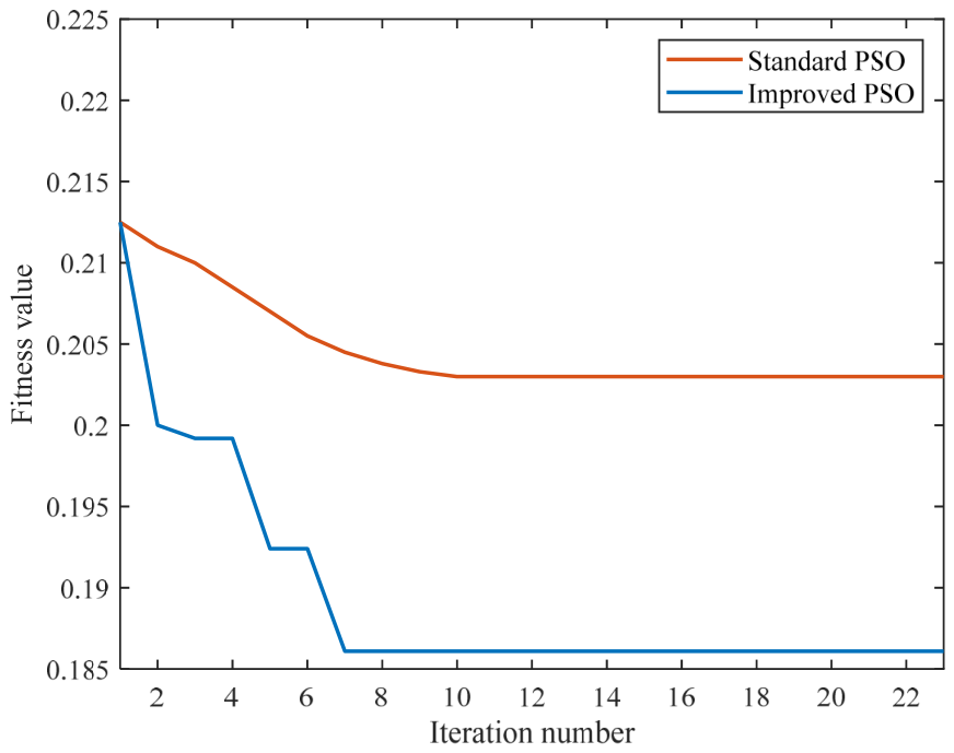
The improved PSO algorithm is applied to the offline optimization of the speed loop PI controller parameters. The integral of time-weighted absolute error (ITAE) of the system speed error is adopted as the fitness function. The optimal PI parameters obtained are K p = 4.273 and K i = 0.336 . The fitness value variation curve is shown in Figure 4. It can be observed that the improved PSO algorithm converges rapidly near the optimal solution after approximately 7 iterations. All key parameter settings of the improved PSO are summarized in Table 2.
To quantitatively evaluate the improvement effect, the standard PSO (fixed inertia weight ω = 0.7 , fixed learning factors c 1 = c 2 = 1.5 ) is implemented under identical conditions for comparison. The convergence curves of the two algorithms are shown in Figure 4, and the comparison results are summarized in Table 3.
Compared with the standard PSO, the convergence iterations of the improved PSO are reduced by 22.2%, the optimal fitness is reduced by 8.4%, and the standard deviation is smaller, indicating superior robustness. These results validate the effectiveness of the collaborative adjustment of learning factors and the chaotic inertia weight strategy in accelerating convergence and improving optimization quality.

5.3. Simulation and Analysis of Speed Loop PI Tuning

To ensure a fair comparison between the conventional PI controller and the proposed PSO−PI controller, the following measures were taken.
The conventional PI gains were determined using the widely adopted Ziegler–Nichols tuning rule as a starting point, followed by fine-tuning based on step-response experiments to achieve a typical dynamic response. This yielded K p = 1.8 and K i = 0.12 . The closed-loop bandwidth of this baseline controller is approximately 48 rad/s, which is comparable to that of the PSO-PI controller, with a difference of less than 10%.
Both controllers were implemented with identical control constraints: an output saturation limit of ±10 V, the same back-calculation anti-windup scheme with K a w = 1.0 , and the same sampling frequency of 10 kHz. Therefore, the reported performance improvements are not artifacts of an unfairly chosen baseline, but, rather, arise from the optimal gain distribution achieved by the PSO-based tuning.
Comparative simulations were carried out under speed step and sudden load conditions.
(1) Speed Step Response
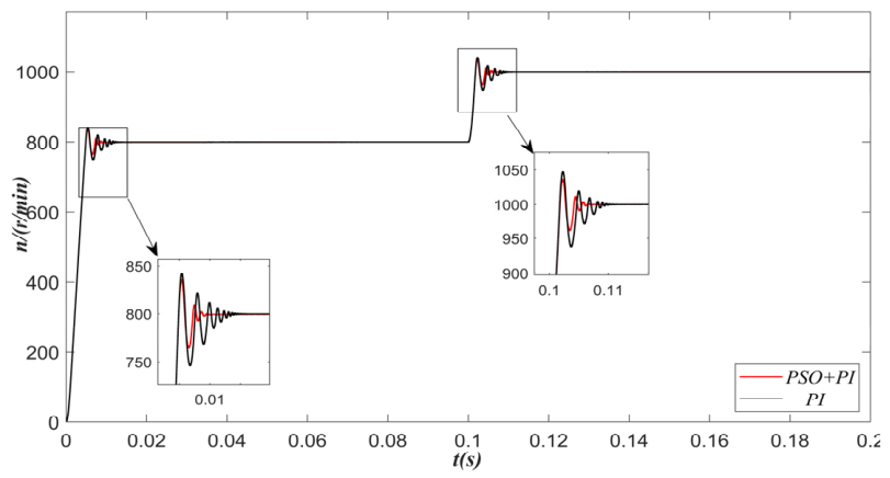
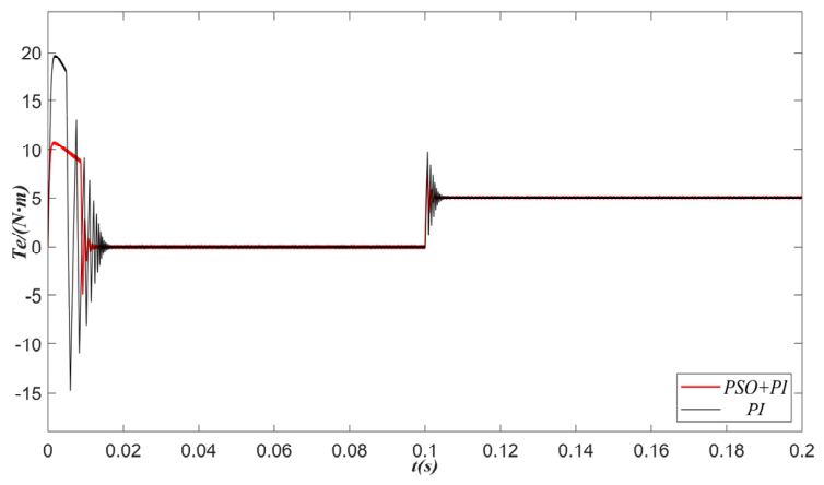
The initial speed was 800 rpm. At t = 0.1 s, the speed was increased to 1000 rpm. The comparison waveforms of speed and torque are shown in Figure 5 and Figure 6.
As shown in Table 4, compared to the traditional PI controller, the PSO-PI controller shortens the settling time during the starting phase by 46.7%, and reduces the speed overshoot by about 23.8%. Meanwhile, the torque overshoot of the PSO−PI controller is significantly lower than that of the conventional PI controller. The above results indicate that the optimized PI controller can achieve a better balance between fast response and damping characteristics, thereby effectively improving the dynamic performance of speed tracking.
(2) Load Disturbance Rejection Capability
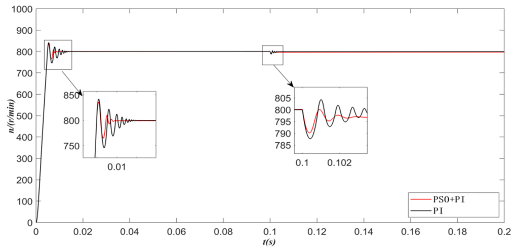
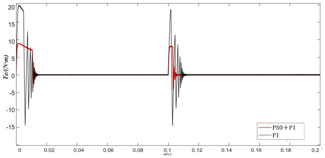
A 5 N.m load is suddenly applied at 0.1 s. The comparative simulation results are shown in Figure 7 and Figure 8.
As shown in Table 5, the speed drop of the PSO−PI controller is only 8 r/min, far better than the 15 r/min of the traditional PI controller. The speed recovery time is shortened by 40%. Moreover, the torque overshoot of the PSO−PI controller is also smaller, indicating that the optimized speed loop possesses stronger load disturbance rejection capability, thereby effectively improving the steady-state accuracy and robustness of the system.


6. Experimental Verification and Analysis

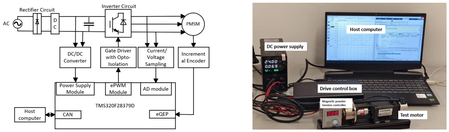
To verify the practical application effect of the proposed control strategy, an experimental platform was built with a TMS320F28379D digital signal processor as the core.

6.1. Experimental Platform

The hardware structure is shown in Figure 9, consisting of a host computer, main control chip (TMS320F28379D, 200 MHz), drive and inverter circuit, test motor, and magnetic powder tension controller. The motor parameters are shown in Table 6.
To evaluate the real-time feasibility of the proposed algorithm, the computational burden is analyzed. The control algorithm is implemented on a TMS320F28379D DSP at 200 MHz with a sampling frequency of 10 kHz (control period T s = 100 μ s ). The execution time per control cycle is measured via the CPU timer. The measured times are approximately 8.0 μ s for the conventional SMO, 10.0 μ s for the fixed-gain ST−SMO, and 12.5 μ s for the proposed AST−SMO. Although the adaptive-gain mechanism adds about 2.5 μ s of overhead, the total remains far below the 100 μ s control period. Flash and RAM utilization are approximately 18% (48 KB/256 KB) and 12% (12 KB/100 KB), respectively. These results confirm that the proposed method satisfies real-time implementation constraints.
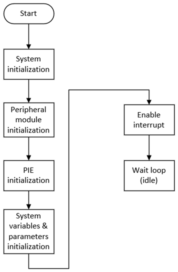
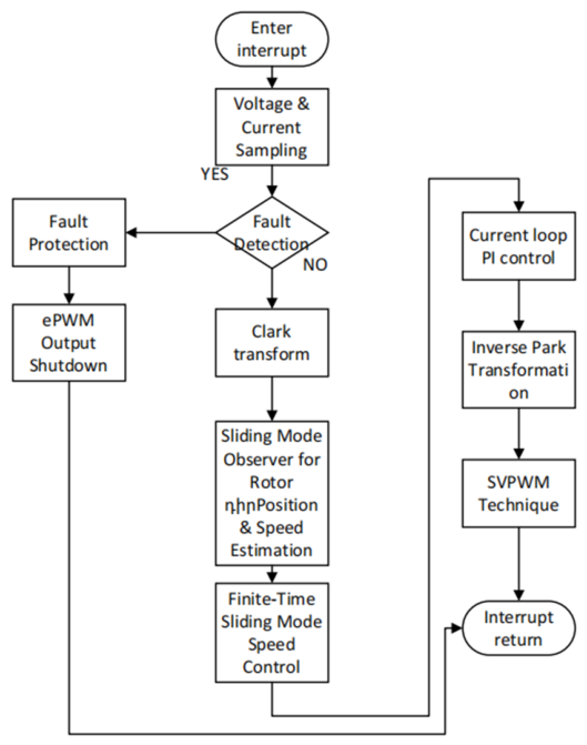
The control software consists of a main program and an interrupt program. The main program is responsible for system initialization; the interrupt program completes voltage and current sampling, coordinate transformation, rotor position and speed estimation, and SVPWM signal generation. The main program flowchart and the interrupt flowchart are shown in Figure 10 and Figure 11, respectively.
6.2. Analysis of Experimental Results

(1) Analysis of Improved PSO−PI Speed Controller Results
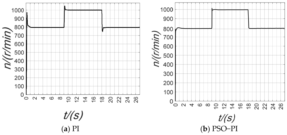
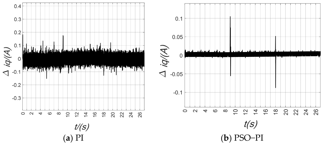
The motor was started with no load to 800 r/min, increased to 1000 r/min, and then decreased back to 800 r/min. Figure 12 shows the speed curves, and Figure 13 shows the q-axis current waveforms.
The experimental results demonstrate that during the startup stage, the overshoot of the conventional PI controller is approximately 19.2%, whereas that of the PSO−PI controller is only about 2.5%. The settling times to 1000 r/min are 1.3 s and 0.7 s, respectively. During the acceleration and deceleration stages, the overshoots of the PSO−PI controller are approximately 4.6% and 4.2%, and its recovery times are consistently shorter than those of the conventional PI controller. Moreover, the PSO−PI controller outperforms the conventional PI controller in terms of both steady-state current ripple and dynamic current fluctuations. In conclusion, the improved PSO−PI controller achieves more precise speed regulation capability and faster dynamic response.
(2) Speed step test
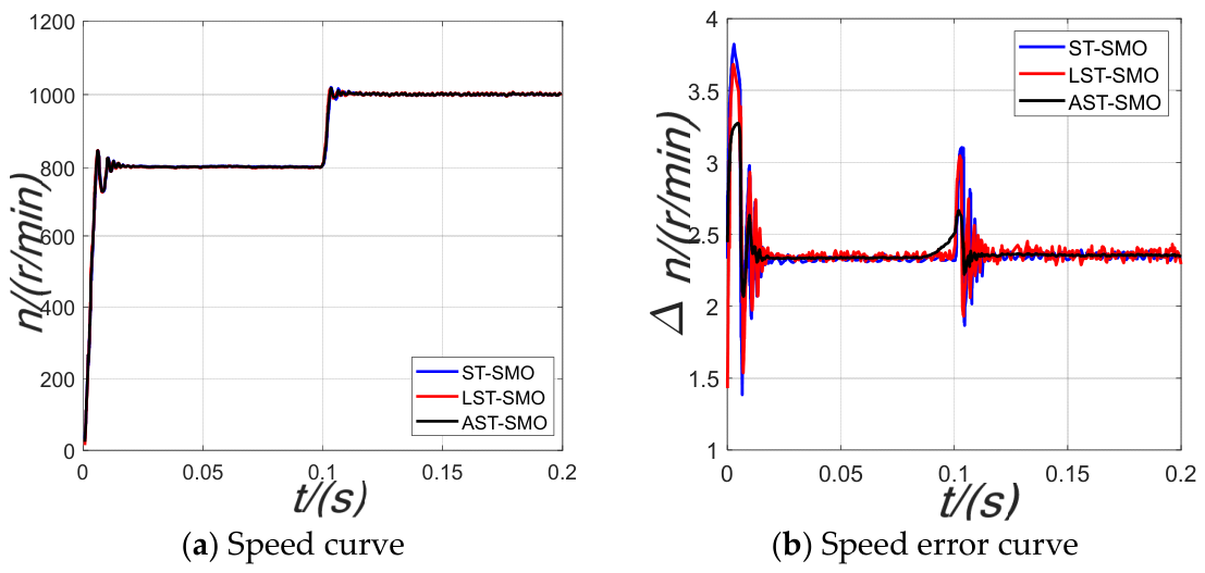
The speed step experiment simulation duration was set to 0.2 s. The target motor speed was set to 800 r/min with no-load start. At 0.1 s, the speed command was stepped up to 1000 r/min.
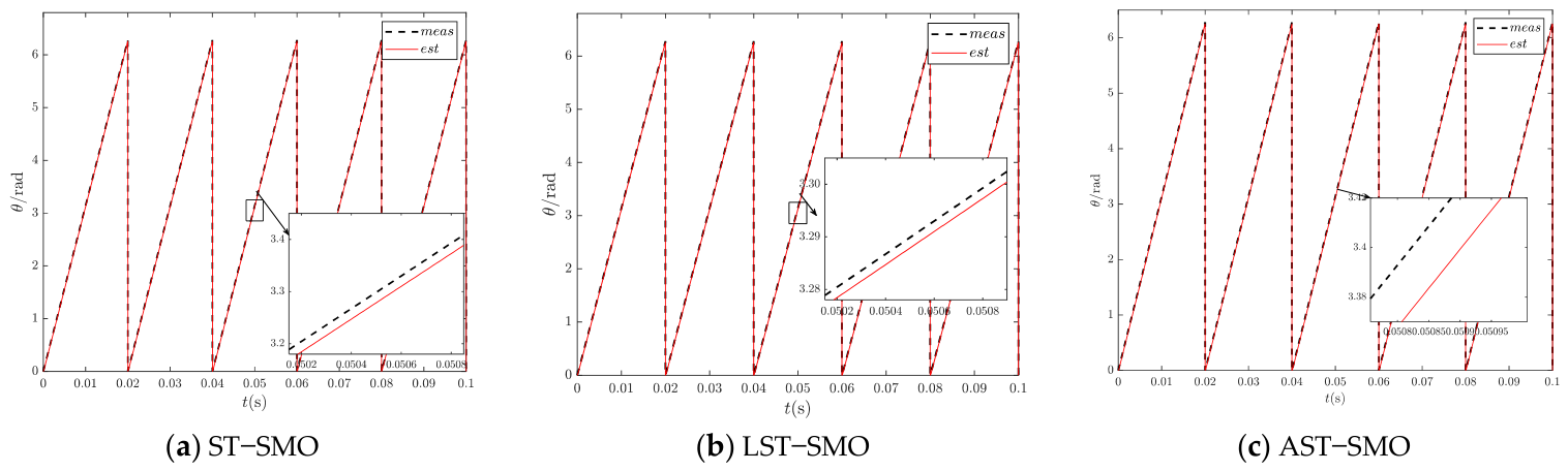
Figure 14 shows the comparison of estimated and actual positions. The ST−SMO estimated position exhibits high-frequency sawtooth fluctuations, indicating a chattering problem, while the estimated positions of LST−SMO and AST−SMO are smooth lines, indicating effective chattering suppression. The rotor estimation error of LST−SMO is 0.012%, and that of AST−SMO is 0.005%, so AST−SMO provides more accurate rotor position observation.
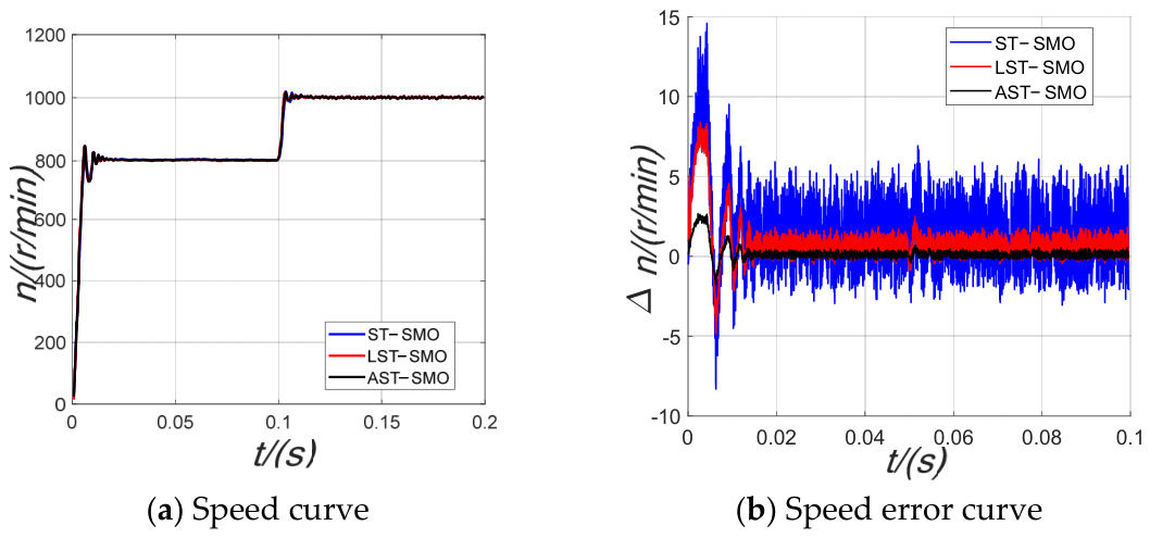
As can be seen from Figure 15, during both sudden speed changes at 0.1s and motor startup, the ST−SMO, LST−SMO, and AST−SMO all track the reference speed well, and the actual and estimated speed curves show a high degree of agreement, indicating that all three observers exhibit good observation performance. A comparison in terms of speed error reveals that, compared with the conventional ST−SMO and the LST−SMO, the AST−SMO demonstrates better observation performance both during speed transients and at motor startup.
(3) Load step test
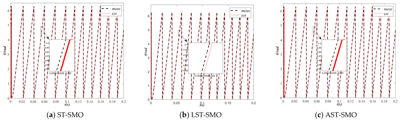
To further verify the control effect, a sudden load change experiment was conducted. The initial speed was 800 r/min. At 0.05 s, a 5 N·m load was suddenly applied. The simulation waveforms are shown in Figure 16 and Figure 17.
The simulation results in Figure 16 indicate that under no-load startup, the estimated positions of the ST−SMO, the LST−SMO, and the AST−SMO closely track the actual position, and they continue to do so after a sudden load change. However, the estimated position from the conventional ST−SMO exhibits high-frequency sawtooth-like fluctuations, revealing a certain chattering problem, whereas the estimated positions from the LST−SMO and the AST−SMO appear as smooth lines, demonstrating that these algorithms can effectively suppress system chattering.
Under sudden load change conditions, Figure 17 presents a comparison of the observed and actual speeds in addition to the speed errors for the ST−SMO, LST−SMO, and AST-SMO. Although the system can restore the original speed within a certain time after a sudden load increase, the comparison reveals that the AST−SMO exhibits a shorter dynamic response time during load changes and smaller speed fluctuations when reaching steady state. At startup, the maximum error between the observed and measured speeds can reach 15 r/min for the ST−SMO, 9 r/min for the LST−SMO, and 3 r/min for the AST-SMO. Under a sudden load change, the maximum speed error reaches 7 r/min for the ST−SMO, 3 r/min for the LST−SMO, and 1 r/min for the AST−SMO. The above analysis demonstrates that the AST−SMO achieves higher speed estimation accuracy, with greater coincidence and accuracy.

7. Conclusions

This paper proposes a PMSM position sensorless control strategy that integrates an AST-SMO with an improved PSO−based speed-loop PI parameter tuning method. To address the poor adaptability of fixed-gain ST−SMO across a wide range of operating conditions, a time-varying gain function with an integral-type adaptive law was designed. This adaptive law automatically adjusts the gain according to the motor operating state, effectively suppressing chattering while maintaining high estimation accuracy under complex conditions. Simulation and experimental results show that the proposed AST−SMO has superior observation performance compared to traditional SMO and fixed-gain ST-SMO. The improved PSO algorithm is employed to optimize the speed-loop PI parameters, further enhancing the dynamic response quality and load disturbance rejection capability. The adopted AST−SMO is grounded in second-order sliding mode theory, which attenuates chattering at the mechanism level without requiring LPFs or additional phase compensation. Its simple structure is advantageous for engineering implementation.

Author Contributions

Conceptualization, H.Z. and Z.W.; methodology, W.L. and C.Z.; software, W.L.; validation, C.Z.; formal analysis, H.Z.; investigation, H.Z. and Z.W.; resources, Z.W.; data curation, H.Z.; writing—original draft preparation, H.Z.; writing—review and editing, W.L., C.Z. and Z.W.; funding acquisition, W.L. All authors have read and agreed to the published version of the manuscript.

Funding

This research was funded by PhD Research Startup Foundation of Hebei Normal University, Grant Number L2024B37.

Data Availability Statement

All contributions presented in this study are original and are included in the article. Further inquiries may be directed to the corresponding author.

Conflicts of Interest

The authors declare no conflicts of interest.

Abbreviations

The following abbreviations are used in this manuscript:
SMOSliding Mode Observers
PMSMPermanent Magnet Synchronous Motor
AST-SMOAdaptive-gain Super-twisting Sliding Mode Observer
PSOParticle Swarm Optimization
LPFLow-pass Filter
PLLPhase-Locked Loop
ST-SMOSuper-Twisting Sliding Mode Observer
SOGISecond-order Generalized Integrator
ITAEIntegral Time Absolute Error

References

  1. Kumar, S.; Singh, B. Sensorless adaptive SMO with mixed order generalized integrator based improved QPLL PMSM drive for LEV application. IEEE Trans. Ind. Appl. 2024, 60, 9100–9110. [Google Scholar] [CrossRef] [Scilit]
  2. Zhang, H.; Ma, X.; Fan, P.; Xing, Z.; Ma, J.; Gao, Y. A robustness enhancement strategy for Three-Vector model predictive current control based on Back-EMF compensation via sliding mode observer. World Electr. Veh. J. 2026, 17, 333. [Google Scholar] [CrossRef] [Scilit]
  3. Zou, X.; Yang, K.; Luo, Y. Sensorless control of permanent magnet synchronous motor based on two stage low pass filtering sliding mode observer. Soft Comput. 2026, 30, 1377–1390. [Google Scholar] [CrossRef] [Scilit]
  4. Bao, D.; Wu, H.; Wang, R. Full-order sliding mode observer based on synchronous frequency tracking filter for high-speed interior PMSM sensorless drives. Energies 2020, 13, 6511. [Google Scholar] [CrossRef] [Scilit]
  5. Chen, S.; Wu, X.; Chen, J. Second-order lead compensator-based quadrature PLL for sensorless interior permanent magnet synchronous motor control. IET Power Electron. 2020, 13, 568–575. [Google Scholar] [CrossRef] [Scilit]
  6. Hu, J.; Wang, Z.; Wang, H. Gain compensation-based quasi-resonant PLL with adaptive super-twisting SMO for position error suppression of IPMSM sensorless control. IEEE J. Emerg. Sel. Top. Power Electron. 2024, 12, 4888–4899. [Google Scholar] [CrossRef] [Scilit]
  7. Gao, P.; Zhang, G.; Ouyang, H. An adaptive super twisting nonlinear fractional order PID sliding mode control of permanent magnet synchronous motor speed regulation system based on extended state observer. IEEE Access 2020, 8, 53498–53510. [Google Scholar] [CrossRef] [Scilit]
  8. Li, Z.; Wang, J.; Wang, S. Design of sensorless speed control system for permanent magnet linear synchronous motor based on fuzzy super-twisted sliding mode observer. Electronics 2022, 11, 1394. [Google Scholar] [CrossRef] [Scilit]
  9. Zhang, M.; Xiao, F.; Shao, R.; Deng, Z. Robust fault detection for permanent-magnet synchronous motor via adaptive sliding-mode observer. Math. Probl. Eng. 2020, 1, 9360939. [Google Scholar] [CrossRef] [Scilit]
  10. Wu, X.; Hu, X.; Yu, X. Improved Super-Twisting Flux Sliding-Mode Observer for Sensorless IPMSM Drives With FFPS-PLL. IEEE Trans. Transp. Electrif. 2025, 11, 1949–1960. [Google Scholar] [CrossRef] [Scilit]
  11. Tao, S.; Wang, Z.; Li, M. Improved Super-Twisting Sliding Mode Control with a novel extended state disturbance observer for PMSM drives. In Proceedings of the 2024 International Conference on Intelligent Robotics and Automatic Control (IRAC), Guangzhou, China, 29 November–1 December 2024; pp. 427–431. [Google Scholar]
  12. Lin, G.; Li, J. Sensorless control of PMSM based on adaptive super-twisting sliding mode observer. Modular Machine Tool and Autom. Manuf. Tech. 2026, 4, 1–8. [Google Scholar] [CrossRef] [Scilit]
  13. Guo, D.; Pei, Y. Research on motor control strategy of roadheader based on fuzzy supercoil synovial control. Heilongjiang Electr. Power 2026, 48. [Google Scholar]
  14. Sun, H.; Zhang, X.; Liu, X. Adaptive robust sensorless control for PMSM based on super-twisting algorithm back EMF observer and extended state observer. Electr. Eng. 2025, 107, 9295–9307. [Google Scholar] [CrossRef] [Scilit]
  15. Yang, C.; Liu, W.; Song, B. Signal-injection-free online identification of temperature-dependent electrical parameters for SPMSM drives: An alternating dual-adaline approach. IEEE Trans. Transp. Electrif. 2026, 8. [Google Scholar] [CrossRef] [Scilit]
  16. Zhou, R.; Wang, H. Model predictive speed and voltage control of sensorless PMSM with parameter rectification and a reduced-order EKF. IEEE Trans. Ind. Electron. 2026, 8. [Google Scholar] [CrossRef] [Scilit]
  17. Wang, Z.; Zhu, X.; Nie, W. Sensorless control strategy for permanent magnet synchronous motor integral adaptive observer. IEEJ J. Ind. Appl. 2025, 14, 120–130. [Google Scholar] [CrossRef] [Scilit]
  18. Bian, F.; Chien, Y.R. PMSM speed control based on improved adaptive fractional-order sliding mode control. Symmetry 2025, 17, 736. [Google Scholar] [CrossRef] [Scilit]
  19. Moreno, J.A.; Osorio, M. A Lyapunov approach to second-order sliding mode controllers and observers. In Proceedings of the 2008 47th IEEE Conference on Decision and Control, Cancun, Mexico, 9–11 December 2008. [Google Scholar]
  20. Setiawan, M.A.; Setiadi, H.; Indrawan, R.W. Speed controller design using hybrid differential evolution Algorithm-Particle Swarm Optimization for PSMS. J. Adv. Technol. Multidiscip. 2022, 1, 24–29. [Google Scholar] [CrossRef] [Scilit]
Figure 1. Phase-locked loop structure diagram.
Wevj 17 00446 g001
Figure 2. Tracking performance and error comparisons of angular position and velocity for sinusoidal signals.
Wevj 17 00446 g002
Figure 3. Performance evaluation of AST−SMO under parameter mismatches.
Wevj 17 00446 g003
Figure 4. Comparison of convergence curves between standard PSO and improved PSO.
Wevj 17 00446 g004
Figure 5. Speed waveform comparison under speed step.
Wevj 17 00446 g005
Figure 6. Torque waveform comparison under speed step.
Wevj 17 00446 g006
Figure 7. Speed waveform comparison under torque step.
Wevj 17 00446 g007
Figure 8. Torque waveform comparison under torque step.
Wevj 17 00446 g008
Figure 9. Hardware structure of the experimental platform.
Wevj 17 00446 g009
Figure 10. Main program flowchart.
Wevj 17 00446 g010
Figure 11. Interrupt flowchart.
Wevj 17 00446 g011
Figure 12. Speed curves of the two control strategies.
Wevj 17 00446 g012
Figure 13. The q−axis current of the two control strategies.
Wevj 17 00446 g013
Figure 14. Rotor position curves in the speed step experiment.
Wevj 17 00446 g014
Figure 15. Speed and speed error curves in the speed step experiment.
Wevj 17 00446 g015
Figure 16. Rotor position curves in the torque step experiment.
Wevj 17 00446 g016
Figure 17. Speed and speed error curves in the torque step experiment.
Wevj 17 00446 g017
Table 1. Comparison of existing ST-SMO schemes and the proposed AST-SMO.
MethodGain Tuning MechanismPrior BoundTuning EffortRobustness
Fixed-gain ST-SMOFixed constantRequiredLowPoor
Linear-gain ST-SMOLinear error-dependent gainRequiredMediumMedium
Fuzzy Adaptive ST-SMOFuzzy-logic rule schedulerRequiredHighMedium
Classic Adaptive-gain STALyapunov-based adaptation lawNot requiredLowGood
Proposed AST-SMOIntegral type error-driven adaptationNot requiredLowestExcellent
Table 2. Key parameter settings of the improved PSO algorithm.
Population SizeMaximum Iterations K p Ki μ a0min, ωmax]Integration Time Step
30100[0.5, 10][0.01, 5]40.7[0.4, 0.9]100 µs
Table 3. Performance comparison between standard PSO and improved PSO.
IndicatorsStandard PSOImproved PSO
Convergence iterations97
Optimal fitness value (ITAE)0.2030.186
Optimization time (s)4.23.1
Fitness standard deviation (10 runs)0.0210.009
Table 4. Comparison of speed step simulation data.
Control StrategyStarting Overshoot
(r/min)
Starting Settling Time
(s)
Acceleration Overshoot (r/min)Acceleration Settling Time
(s)
Torque Overshoot
(N·m)
PI420.015300.01120
PSO−PI320.008230.0068
Table 5. Comparison of torque step simulation data.
Control StrategyPeak Speed Fluctuation
(r/min)
Speed Settling Time
(s)
Torque Overshoot
(N·m)
PI150.015
PSO−PI80.0063
Table 6. Experimental motor parameters.
Motor ParameterValueMotor ParameterValue
P N / W 64 T e / ( N . m ) 0.2
U N / V 24 L d / m H 0.62
I s / A 4 L q / m H 0.62
n N / ( r p m ) 3000 R / Ω 0.89
p n 4 ψ f / W b 0.0173
Disclaimer/Publisher’s Note: The statements, opinions and data contained in all publications are solely those of the individual author(s) and contributor(s) and not of MDPI and/or the editor(s). MDPI and/or the editor(s) disclaim responsibility for any injury to people or property resulting from any ideas, methods, instructions or products referred to in the content.