Article

Extreme Fast Charging Station for Multiple Vehicles with Sinusoidal Currents at the Grid Side and SiC-Based dc/dc Converters †

by
Dener A. de L. Brandao
1,*,
Thiago M. Parreiras
2,
Igor A. Pires
3 and
Braz J. Cardoso Filho
4
1
Information Technology and Electronics Center, Technical High School, Universidade Federal de Minas Gerais, Belo Horizonte 31270-901, Brazil
2
Department of Electrical Engineering, Centro Federal de Educação Tecnológica de Minas Gerais, Belo Horizonte 30510-000, Brazil
3
Department of Electronics Engineering, Universidade Federal de Minas Gerais, Belo Horizonte 31270-901, Brazil
4
Department of Electrical Engineering, Universidade Federal de Minas Gerais, Belo Horizonte 31270-901, Brazil
*
Author to whom correspondence should be addressed.
This paper is an extended version of our paper published in 2022 IEEE Transportation Electrification Conference and Expo, Asia-Pacific (ITEC Asia-Pacific), Haining, China, 28–31 October 2022, pp. 1–6.
World Electr. Veh. J. 2026, 17(4), 215; https://doi.org/10.3390/wevj17040215
Submission received: 27 February 2026 / Revised: 29 March 2026 / Accepted: 16 April 2026 / Published: 18 April 2026
(This article belongs to the Special Issue Power and Energy Systems for E-Mobility, 2nd Edition)

Abstract

Extreme fast charging (XFC) infrastructure is becoming increasingly necessary as the number of electric vehicles continues to grow. However, deploying such stations introduces several challenges related to power quality and compliance with regulatory standards. This work presents an alternative XFC station designed for charging multiple vehicles while ensuring low harmonic distortion in the grid currents, without the need for sinusoidal filters, by employing the Zero Harmonic Distortion (ZHD) converter. The proposed system offers galvanic isolation for each charging interface and supports additional functionalities, including the integration of Distributed Energy Resources (DERs) and the provision of ancillary services. These features are enabled through the combination of a bidirectional grid-connected active front-end operating at low switching frequency with high-frequency silicon carbide (SiC)-based dc/dc converters on the vehicle side. Hardware-in-the-loop (HIL) simulation results demonstrate a total demand distortion (TDD) of 1.12% for charging scenarios involving both 400 V and 800 V battery systems, remaining within the limits specified by IEEE 519-2022.

1. Introduction

In recent years, multiple countries have engaged in discussions regarding the impact of pollutant gas emissions in the atmosphere. These discussions often take place during meetings held under the United Nations Framework Convention on Climate Change (UNFCCC) [1], where climate-related challenges are addressed. As a result, governments establish regulations across different sectors to meet the commitments defined in international agreements.
The transportation sector is one of the key areas targeted by such regulations. Electrifying the vehicle fleet has emerged as an important strategy to reduce emissions. Nevertheless, charging time remains a major concern for users. Although lower-power chargers allow for convenient overnight charging, certain applications demand significantly shorter charging times, particularly in urban environments. This includes individual and public transportation, as well as highway scenarios, such as long-distance travel to regions with limited charging infrastructure, intercity buses, and freight trucks [2,3]. Additionally, off-road vehicles also require ultra-fast charging solutions [4].
Several projects have been developed to install charging points in different locations. The Federal Highway Administration (FHWA), an agency of the US Department of Transportation, proposed minimum standards for the country’s road network through the National Electric Vehicle Infrastructure Formula Program [5]. The document suggests four charging stations with a minimum power of 150 kW at each charging point, which, in turn, should be positioned 50 miles away and less than 2 km from highways. In addition, the document proposes installing 500,000 chargers by 2030.
Charging infrastructure must comply with limits on harmonic injection into the grid. International guidelines, such as IEEE Std 519-2022 [6], are adopted in many countries for this purpose. Thus, beyond the technical challenges associated with high-power charging, there are also important regulatory constraints to be addressed.
In addition, IEEE Std 2030.1.1-2021 [7] establishes technical requirements for dc extreme fast charging systems. For stations designed to charge multiple vehicles simultaneously, the standard requires galvanic isolation between the outputs, which restricts the use of certain converter topologies proposed in the literature [8].
Several studies in the literature investigate extreme fast charging (XFC) stations designed for multiple vehicles operating in low-voltage networks, typically around 400 V [9,10,11]. However, higher-power applications generally require connection to medium-voltage grids, which introduces the need for an additional power conversion stage to step down the voltage, often implemented using low-frequency transformers.
Moreover, the ANSI/UL 2202 [12] standard for XFC stations does not cover equipment with input voltages above 600 V, which limits the feasibility of converter topologies directly interfaced with medium-voltage networks [13]. As a consequence, most commercial XFC solutions are designed to operate with input voltages up to 480 Vac [14].
Several of the proposed solutions lack galvanic isolation, which is essential for user protection against electric shock and for compliance with standards such as IEC 62955:2018 and IEC 61851-1:2017 [15,16]. Transformerless approaches continue to face both technical and regulatory challenges [17]. On the other hand, some applications adopt converters based on solid-state transformers (SSTs) operating at high frequencies, enabling a significant reduction in transformer size while still maintaining galvanic isolation [18,19]. However, they do not provide galvanic isolation from the electrical grid and do not comply with the voltage requirements of UL 2202.
Regarding medium-voltage power electronic system protection, devices must interrupt fault current within a few hundred microseconds. Today, medium-voltage electromechanical devices interrupt faults in tens of milliseconds; faster interruption requires solid-state or hybrid circuit breakers, still under development [20]. Also, switches in converters directly connected to the medium-voltage grid may not meet IEC 60060-1:2010 high-voltage test requirements [21], which are needed for robustness against lightning strikes [22].
Table 1 summarizes key aspects of different studies on topologies and prototypes for extreme fast charging stations. The following aspects are analyzed in Table 1: which grid-connected converter topologies and dc/dc converters are used; whether they comply with IEEE 2030.1.1-2017, IEEE 519-2022, and UL 2202 standards; the number of diodes and switches; the switch technology; the switching frequency; the simulated or prototype power; and, finally, the current total harmonic distortion (THD). From Table 1, it can be observed that many of the alternatives presented in the literature fail to meet essential regulatory requirements for commercial applications.
It is important to note that the performance of all these systems, including the proposed one, is highly dependent on the adopted control strategy and its parameters. In the case of the proposed converter, the achieved power quality in XFC applications results from the appropriate modulation strategy and control implementation, as detailed in the following sections. Therefore, a comprehensive assessment of the control strategies used in the referenced systems is beyond the scope of this paper.
This paper proposes an XFC station architecture for charging multiple electric vehicles, combining advanced ac/dc and dc/dc converter technologies. The system ensures grid-friendly operation by delivering sinusoidal currents in the absence of capacitive filters, complying with standards such as IEEE Std 519-2022, IEEE Std 2030.1.1-2017 and UL 2202, and avoiding resonance issues.
The proposed solution integrates a step-up transformer for medium-voltage connection while avoiding the use of semiconductor devices on the medium-voltage side, increasing robustness. It also provides galvanic isolation between the grid and chargers, as well as among chargers, and enables ancillary services such as reactive power support. On the vehicle side, the architecture supports both 400 V and 800 V battery systems using the same hardware through SAB converters in an input-parallel output-series (IPOS) configuration, meeting standards such as UL 2202. Additionally, a novel current control strategy for the ZHD converter is introduced, ensuring low harmonic distortion and reliable operation across different charging scenarios.
This paper is an improved version of the work presented in [26]. New references and figures are added, as well as a textual revision. The design of an output voltage controller for the dc/dc converters is a new addition to the work. There is also an expansion of the ZHD converter control design section. Finally, hardware-in-the-Loop (HIL) results are added to present the practical implementation of the converter controllers in a real-time simulation environment with battery recharges with 400 V and 800 V architectures.
The present work is limited to dealing with the proposed configuration in a real-time simulation environment. Therefore, some design issues such as efficiency and cooling system specifications are not directly addressed by the results, although they can be discussed based on the up-to-date literature.
The efficiency of the ZHD converter under different scenarios, as well as comparative information with other topologies in terms of filter capacitor usage, number of semiconductor devices, switching frequency, and current THD, was already presented in [25]. For the output dc/dc converters, the benefits of using silicon carbide (SiC) devices over the silicon (Si) ones are well established in the literature [27,28,29] and the efficiency of SAB converters is typically above 90% [30,31]. Due to the high-power nature of these applications, a dedicated high-capacity cooling system is needed, either air cooling, as in the Tesla Supercharger V3 [32], or water cooling, as in the Tesla Supercharger V4 [33]. Future chargers are expected to use this cooling method even for the cables themselves [34].
The paper begins with this Introduction. Section 2 explores the converters used in the proposed XFC station. The design of controllers is covered in Section 3. Section 4 presents simulation results and Section 5 presents HIL results, which are discussed in Section 6. Section 7 concludes the paper.

2. Proposed Extreme Fast Charging Station for Multiple Vehicles

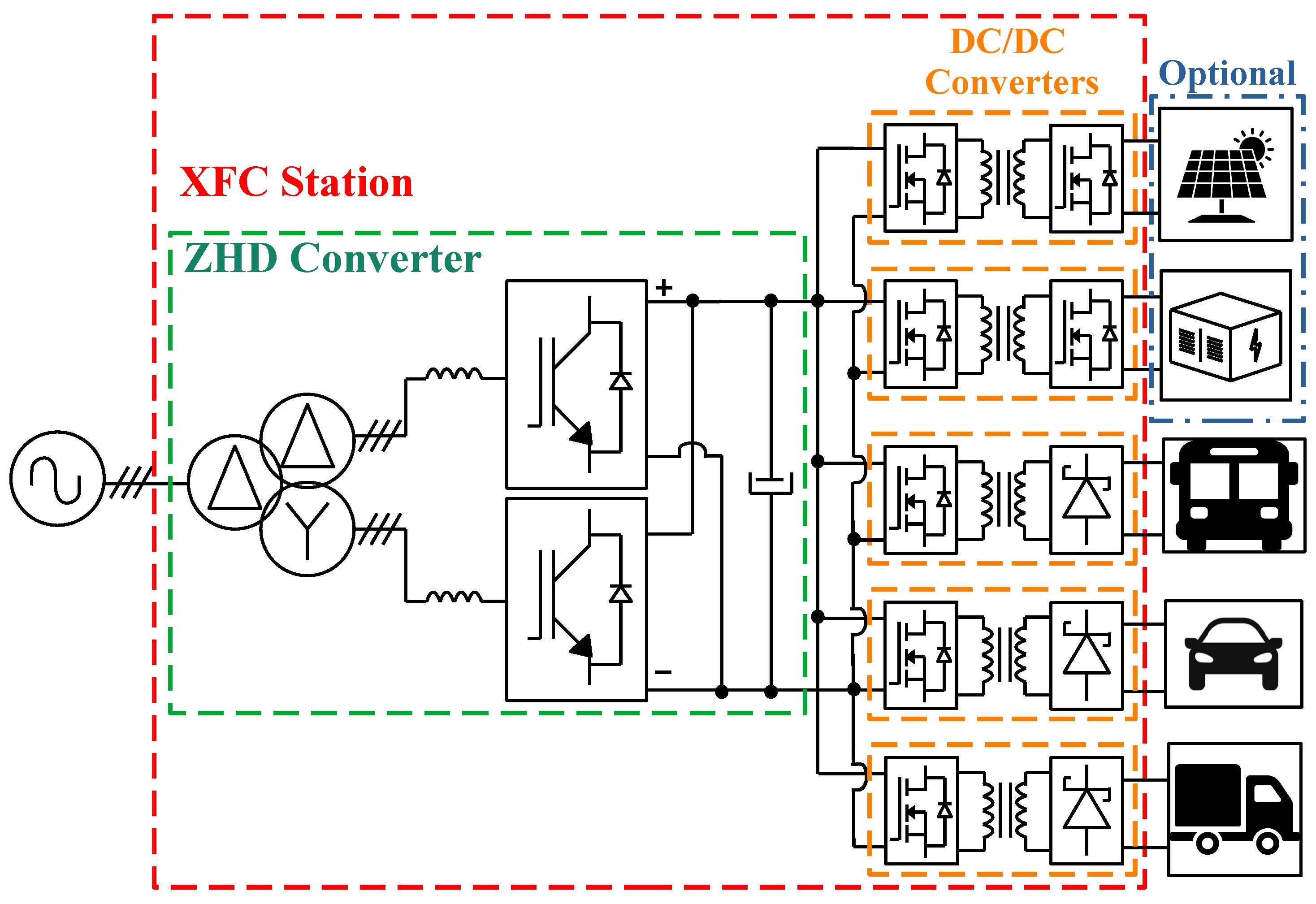
A solution with a low-frequency transformer connected to the grid is interesting to meet current regulatory and technical requirements. Additionally, galvanic isolation is also a requirement among XFC output ports. Motivated by these aspects, this paper proposes an XFC station architecture that employs the Zero Harmonic Distortion (ZHD) converter as the grid-side front-end, combined with SiC-based dc/dc converters dedicated to each charging port. The overall configuration of the proposed XFC station is illustrated in Figure 1.
The ZHD converter has also been presented as a solution for recharging electric buses equipped with supercapacitors [25]. That charger configuration comprised the ZHD and a non-isolated interleaved dc–dc converter, with the ZHD three-winding transformer ensuring galvanic isolation from the power grid. In the present paper, in addition to this grid galvanic isolation, the SiC-based SAB converters ensure galvanic isolation among different vehicles during the charging process.
As the several output ports operate simultaneously with systems that may differ by the type of battery packs (i.e., 400 V and 800 V), the current state of charge (SoC) and the charging mode (i.e., constant current or constant voltage), a dedicated dc/dc converter is provided for each one. Furthermore, this type of structure can accommodate inclusion of Distributed Energy Resources (DERs) using bidirectional converters instead of the unidirectional ones for the charging ports.

2.1. The ZHD Converter

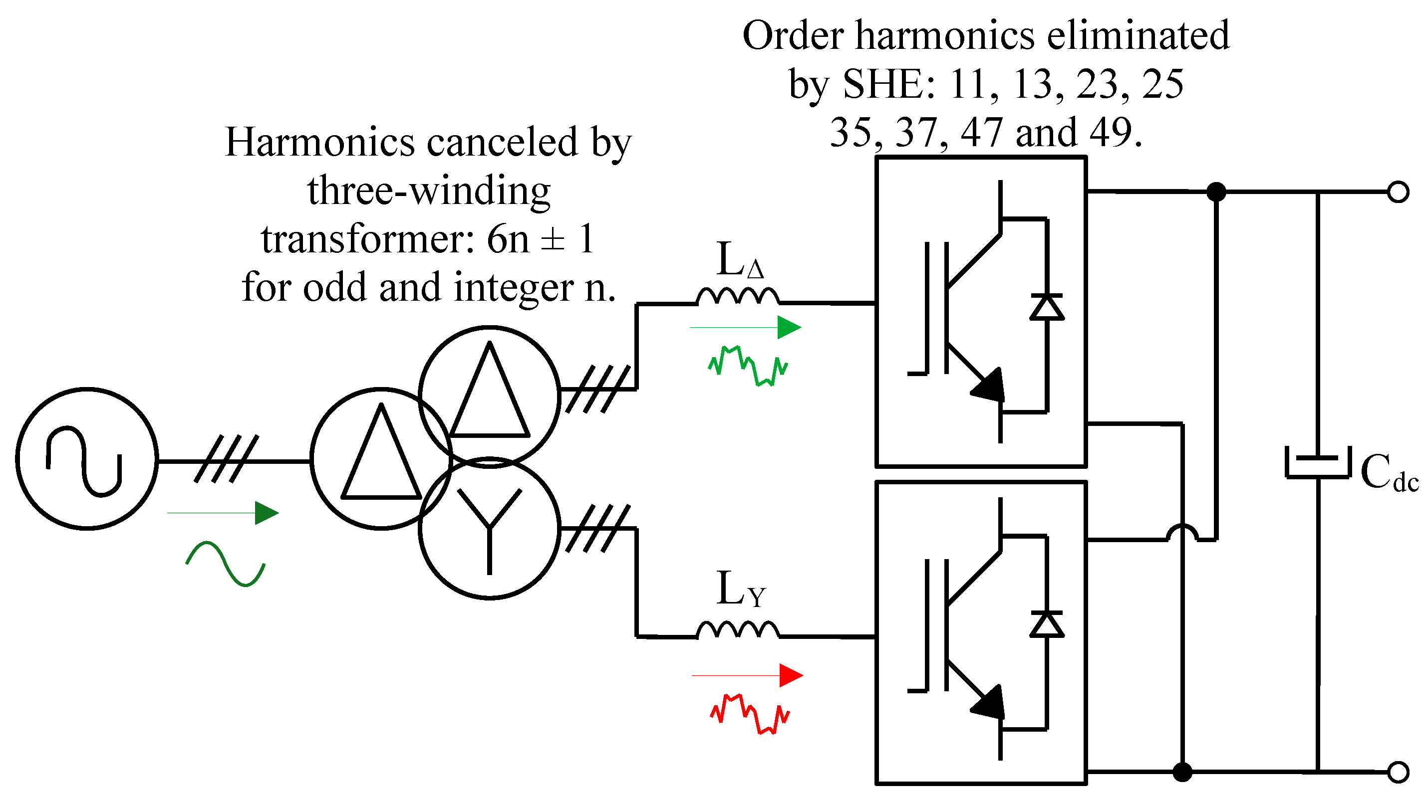
The ZHD converter, previously referred to as the True Unity Power Factor (TUPF) converter, has been reported in the literature as an effective solution for applications in metallurgy, renewable energy systems, and electric mobility [35,36,37]. The topology of the ZHD converter is depicted in Figure 2.
It consists of a three-winding transformer interfaced with the medium-voltage grid, input reactors to mitigate current ripple in the secondary windings, and two- or three-level Voltage Source Converters (VSCs) operating with nine-pulse selective harmonic elimination pulse width modulation (SHE-PWM).
The three-winding transformer provides galvanic isolation between the low-voltage power electronics and the medium-voltage grid, while also enabling the cancellation of harmonics of order 6 n ± 1 , where n is an odd integer, due to the configuration of its secondary windings. In addition, the SHE-PWM technique suppresses harmonics of order 6 k ± 1 , where k is an even integer until eight, in the VSC output voltages. As a result, nearly sinusoidal grid currents are obtained at low average switching frequencies (e.g., 1.14 kHz for a two-level VSC with a 60 Hz fundamental), without the need for capacitive filtering. This stage handles the highest power levels in the XFC station and is implemented using Si-based semiconductor devices.
The ZHD converter, employed as the front-end of the proposed XFC station, enables the integration of local DERs, such as photovoltaic (PV) systems and battery energy storage systems (BESSs), mitigating power peaks at the grid caused by the intermittent charging demand. Additionally, it is capable of providing ancillary services, including reactive power support [37]. Within the context of dc microgrids, the combined use of the ZHD converter and BESS further enhances operational flexibility, allowing increased self-consumption of locally generated photovoltaic energy and, consequently, reducing operational costs for the charging station owner [38].

2.2. DC/DC Converter

Single Active Bridge (SAB) topology [39] is the base for the dc/dc converter responsible for recharging the vehicle battery. In contrast to its bidirectional counterpart, the Dual Active Bridge (DAB), the SAB employs a diode rectifier at the output stage, eliminating the need for gate driver circuits. As a result, the SAB can achieve higher power density, specific power, and efficiency, when compared to the DAB [40]. The IEEE 2030-1-1-2021 standard states that there should be no reverse current flow from the traction to the charger, making the SAB converter a more suitable, simple, and compact solution [41].
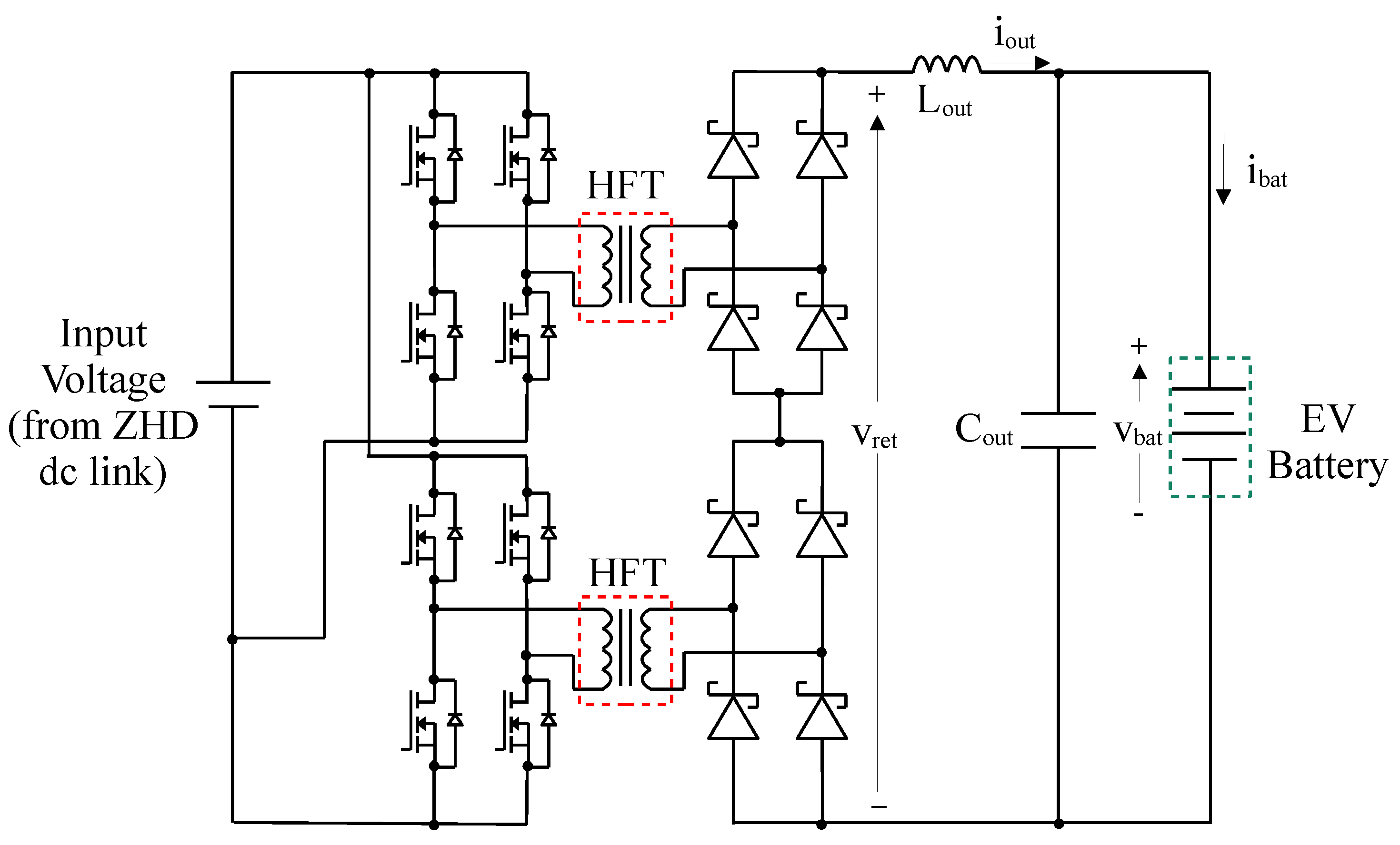
Figure 3 illustrates the proposed isolated dc/dc stage, in which two SAB converters are connected in an IPOS arrangement, enabling a boost characteristic from input to output. This configuration is particularly suitable for supplying high-voltage batteries (e.g., 800 V or above), as it allows all active switches (both in the SAB converters and in the input active rectifier discussed previously) to operate with lower blocking voltage ratings (e.g., 1200 V). In this case, only the output passive rectifiers are required to withstand higher blocking voltages (e.g., 1700 V or higher), contributing to a reduction in the overall system cost.
SiC-based devices eliminate the need for resonant circuits and enable operation at higher transformer fundamental frequencies (e.g., 20 kHz or higher), owing to their reduced switching and conduction losses compared to conventional silicon devices. All employed SiC diodes are of the Schottky type, thereby avoiding reverse recovery losses.
Each SAB operates under the Voltage Cancellation PWM technique, in which all switches are driven with a duty cycle of 0.5, and the overlap angle ( α ) between the half-bridge waveforms determines the resulting three-level output voltage [42]. This strategy further reduces switching losses, as each device commutates only once per fundamental period. Moreover, a 90° phase shift is introduced between the output waveforms of the two SAB converters, contributing to the attenuation of the overall output ripple.
Thus, the average output voltage of the dc/dc converter ( v r e t )is expressed by (1), where the subtractive term accounts for the finite diode commutation interval caused by the transformer leakage inductance ( L s ).
v r e t = 2 a · v d c 1 α π 8 L s i o u t f s w
where v d c is the input dc-link voltage, a is the high-frequency transformer (HFT) ratio, i o u t is the dc/dc converter output current, and f s w is the switching frequency.

3. Control Design

3.1. ZHD Control Design

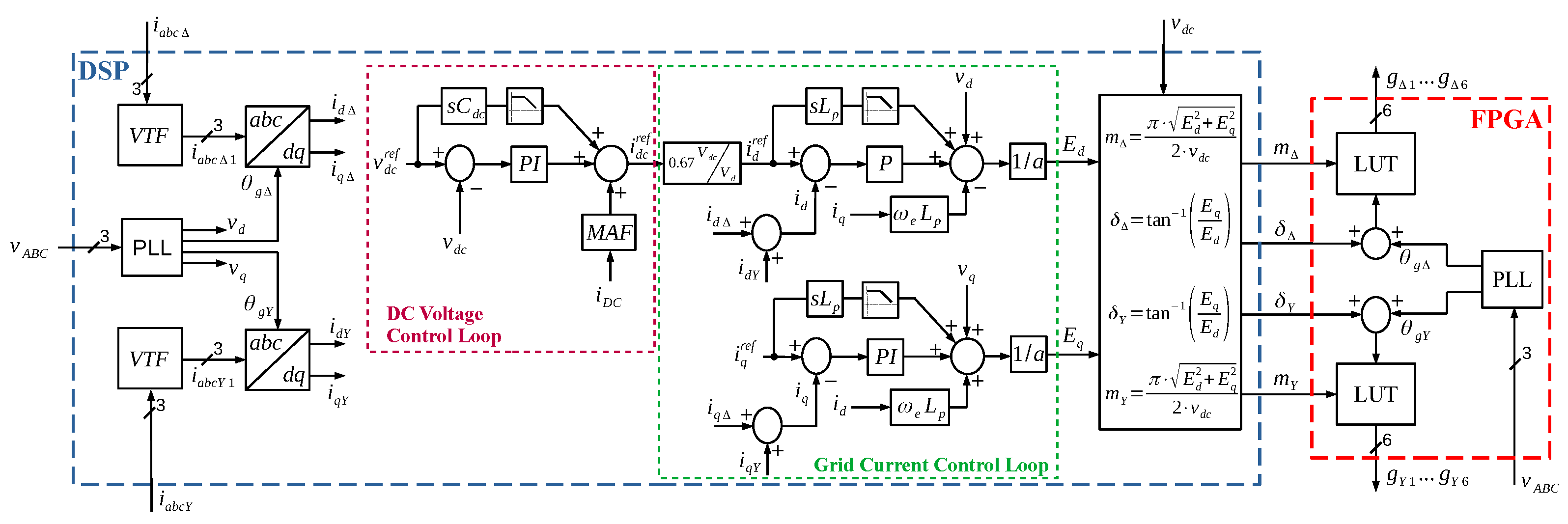
Figure 4 shows the control scheme of the ZHD converter. A phase-locked loop (PLL) receives the voltages measured on the grid. The PLL generates the phase angles of the secondaries in delta and wye, θ g Δ and θ g Y , respectively. In this way, one obtains the decoupled current components for active power (in the d-axis, i d ) and reactive power (in the q-axis, i q ).
The dc-link voltage control loop provides the active power reference. A proportional–integral controller, feedforward of the disturbance signal (current drawn from the dc link i d c ), and feedforward of the reference signal make up the dc-link voltage control loop. A moving average filter (MAF) is used in i d c to filter out the high-frequency components demanded by dc/dc converters.
Currents measured in the transformer secondaries are filtered using a Virtual Transformer Filtering (VTF) technique. This technique emulates the harmonic cancellation of a three-winding transformer, extracting only the fundamental component of the current with minimum delay [36].
Unlike the current control presented in [25], in which the control is performed individually for each converter, the present paper proposes a total current control strategy, such that the same modulation index is applied to both converters within the ZHD. Individual control of each converter may lead to different modulation indices, which can result in current imbalance in the secondary windings and, consequently, imperfect harmonic cancellation in the transformer. A unified control strategy ensures that both converters synthesize voltages with the same modulation index, preventing current imbalance between them. Feedback control strategies, axis decoupling, disturbance signal feedforward ( v d for active power and v q for reactive power), and reference signal feedforward make up the total grid current control loop.
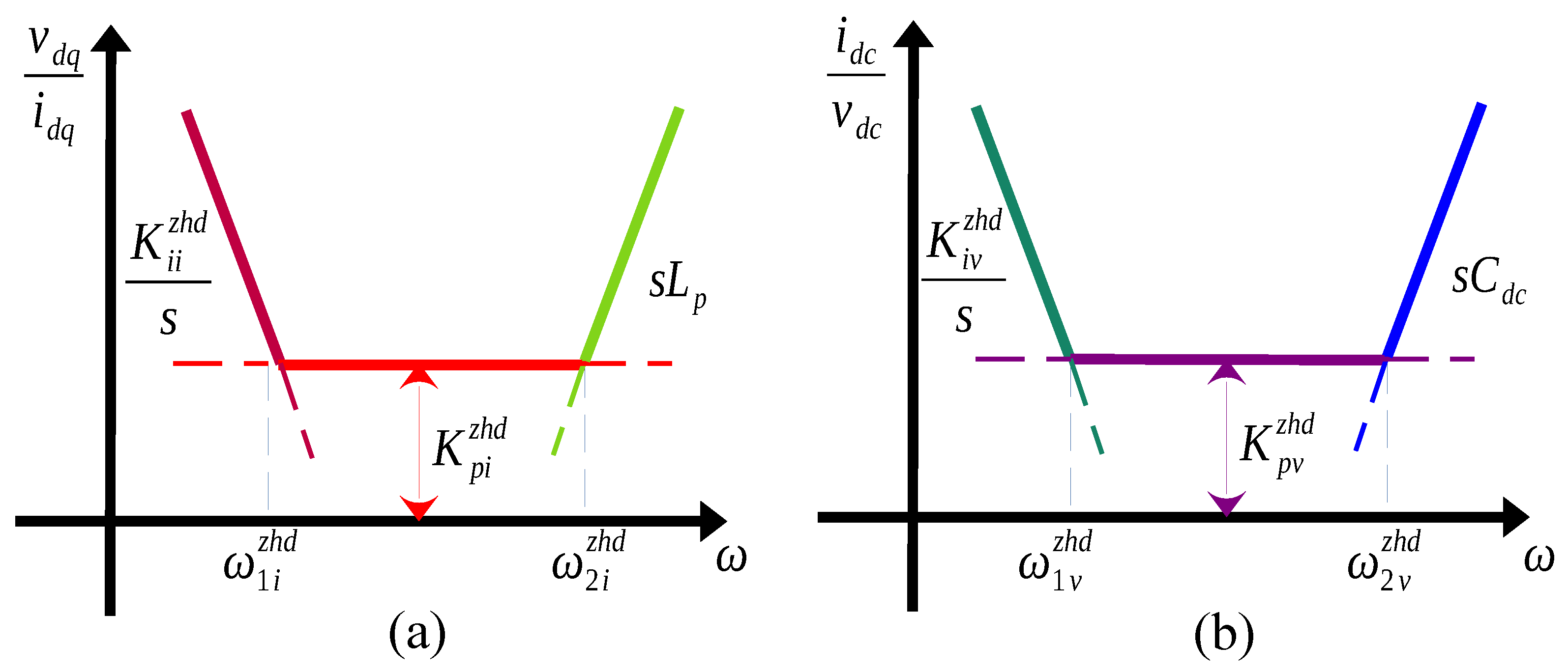
The controller gains are determined by analyzing the disturbance–output relationships, commonly referred to as dynamic stiffness, as defined in electrical motor motion control [43]. The zeros of the dynamic stiffness correspond to the poles of the transfer function. For current control, the relationship is defined in (2) and illustrated in Figure 5a by its asymptotic approximation, where the disturbances correspond to the grid voltage components v d and v q . The parameter L p denotes the equivalent inductance referred to the transformer primary side. The gains K p i z h d and K i i z h d represent the proportional and integral terms of the ZHD converter current controller, respectively.
For dc-link voltage control, the dynamic stiffness is defined in (3) and its asymptotic approximation depicted in Figure 5b, where the disturbance corresponds to the current drawn from the dc link by the dc–dc converters. The parameter C d c represents the dc-link capacitance. The gains K p v z h d and K i v z h d denote the proportional and integral terms of the ZHD converter voltage controller, respectively.
v d q i d q = s L p + K p i z h d + K i i z h d s
i d c v d c = s C d c + K p v z h d + K i v z h d s
Table 2 presents the controllers gains of the ZHD converter. Equations (4) and (5) describe the calculation of the current controller gains, while (6) and (7) present the voltage controller gains of the ZHD. ω 2 i z h d and ω 1 i z h d denote the bandwidth frequencies of the current controller. Similarly, ω 2 v z h d and ω 1 v z h d correspond to the bandwidth frequencies of the voltage controller. For the current control, the pole frequency is one decade below the first eliminated harmonic order (660 Hz, which will appear as 720 Hz in the synchronous rotating reference frame). For voltage control, the frequencies are one decade apart from the current control pole. This approach is used to obtain good disturbance rejection in all frequency ranges, while having a stable and overdamped system response (i.e., real negative transfer function poles).
K p i z h d = ω 2 i z h d · L p
K i i z h d = ω 1 i z h d · K p i z h d
K p v z h d = ω 2 v z h d · C d c
K i v z h d = ω 1 v z h d · K p v z h d
The output of the current controllers produces the reference voltage for VSCs ( E d and E q ). These voltages are duly converted to the modulation indices ( m Δ and m Y ) and to the phase shift angles ( δ Y and δ Δ ) by taking into consideration the VSCs’ dc voltage ( V D C ).
The switching angles are defined based on modulation indices, calculated offline using Newton’s method, and stored in look-up tables (LUTs). The output angles of these LUTs are compared with the sum of the grid phase angles ( θ g Y and θ g Δ ) and the desired phase shifts ( δ g Y and δ g Δ ), generating the IGBTs gate pulses ( g Y 1 g Y 6 and g Δ 1 g Δ 6 ).
SHE modulation requires a large amount of data and significant computational effort to generate high-resolution switching angles. For this reason, the ZHD control is divided into two parts, as illustrated in Figure 4. The dc-link voltage and grid current control loops are implemented on a Digital Signal Processor (DSP), while a Field-Programmable Gate Array (FPGA) executes the SHE PWM using the modulation indices provided by the DSP. High-speed parallel communication between the DSP and FPGA ensures efficient data exchange between the devices, as detailed in Section 5.

3.2. DC/DC Converter Control Design

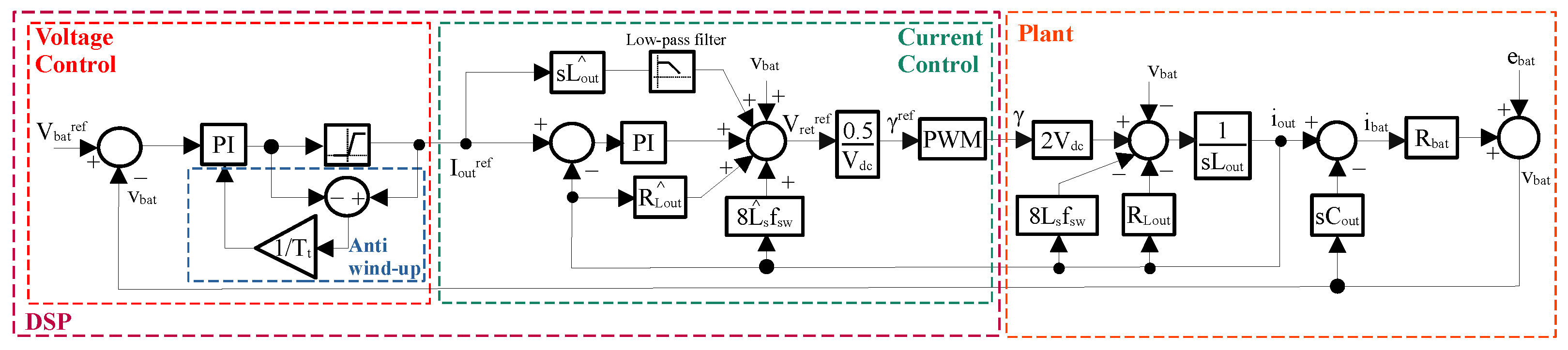
The constant current/constant voltage (CC-CV) method is the most widely used charging strategy for Li-ion batteries [14]. In this work, the conventional CC-CV approach is adopted, with the voltage control loop operating in cascade with the current control loop, thus preserving the characteristics of the CC-CV charging profile. Figure 6 presents the implemented control scheme for the dc/dc converter, where γ = 1 α / π .
The output current control of the dc/dc converter consists of a feedback loop, an internal decoupling loop to compensate for the voltage drop across the output inductor resistance ( R L o u t ), an external disturbance decoupling related to the battery voltage ( v b a t ), and feedforward actions that account for the output inductor dynamics and the voltage drop during the diode commutation interval.
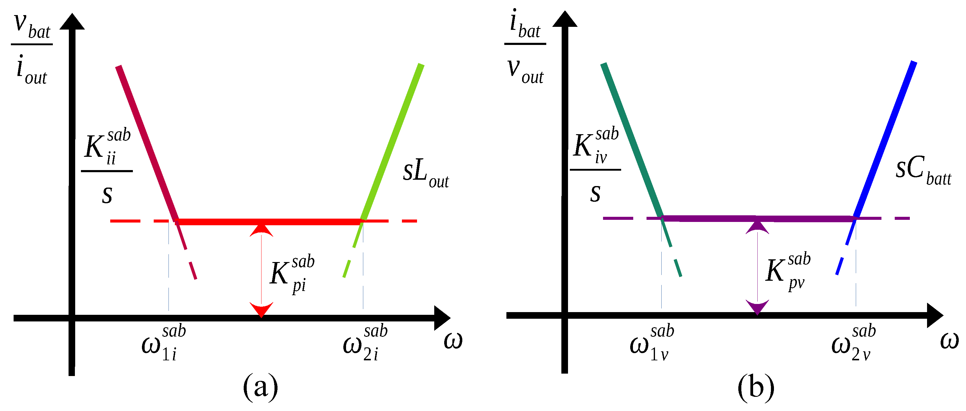
The tuning of the current controller is performed by analyzing the system dynamic stiffness, defined in (8) and illustrated in Figure 7a, and by placing the fastest pole at least one decade below the switching frequency.
v b a t i o u t = s L o u t + K p i s a b + K i i s a b s
The voltage control loop is implemented using a PI controller, whose output is limited by a saturation block set to the maximum allowable current for the application. This approach, as adopted in [44] for battery charging, enables a straightforward CC-CV control strategy [45]. An anti-windup mechanism is included to prevent integrator accumulation when the controller operates in saturation.
Equation (9) presents the dynamic stiffness of the voltage controller and is illustrated in Figure 7b. C b a t t represents the battery modeled as a large capacitor [44], adopting the same controller tuning strategy used for the ZHD converter.
i b a t v o u t = s C b a t t + K p v s a b + K i v s a b s
Equations (10) and (11) define the calculation of the current controller gains, while (12) and (13) present the voltage controller gains of the SAB. ω 2 i s a b and ω 1 i s a b represent the bandwidth frequencies of the current controller. Likewise, ω 2 v s a b and ω 1 v s a b correspond to the bandwidth frequencies of the voltage controller. Table 3 presents the gains of SAB controllers. The voltage control loop frequencies account for the slow dynamics of the battery and, therefore, are low, with periods on the order of minutes.
K p i s a b = ω 2 i s a b · L o u t
K i i s a b = ω 1 i s a b · K p i s a b
K p v s a b = ω 2 v s a b · C b a t t
K i v s a b = ω 1 v s a b · K p v s a b

4. Simulation Results

Table 4 presents the characteristics of the ZHD converter, the high-frequency transformer [46], the dc/dc converter, and the battery bank, based on the Tesla Model S battery bank.
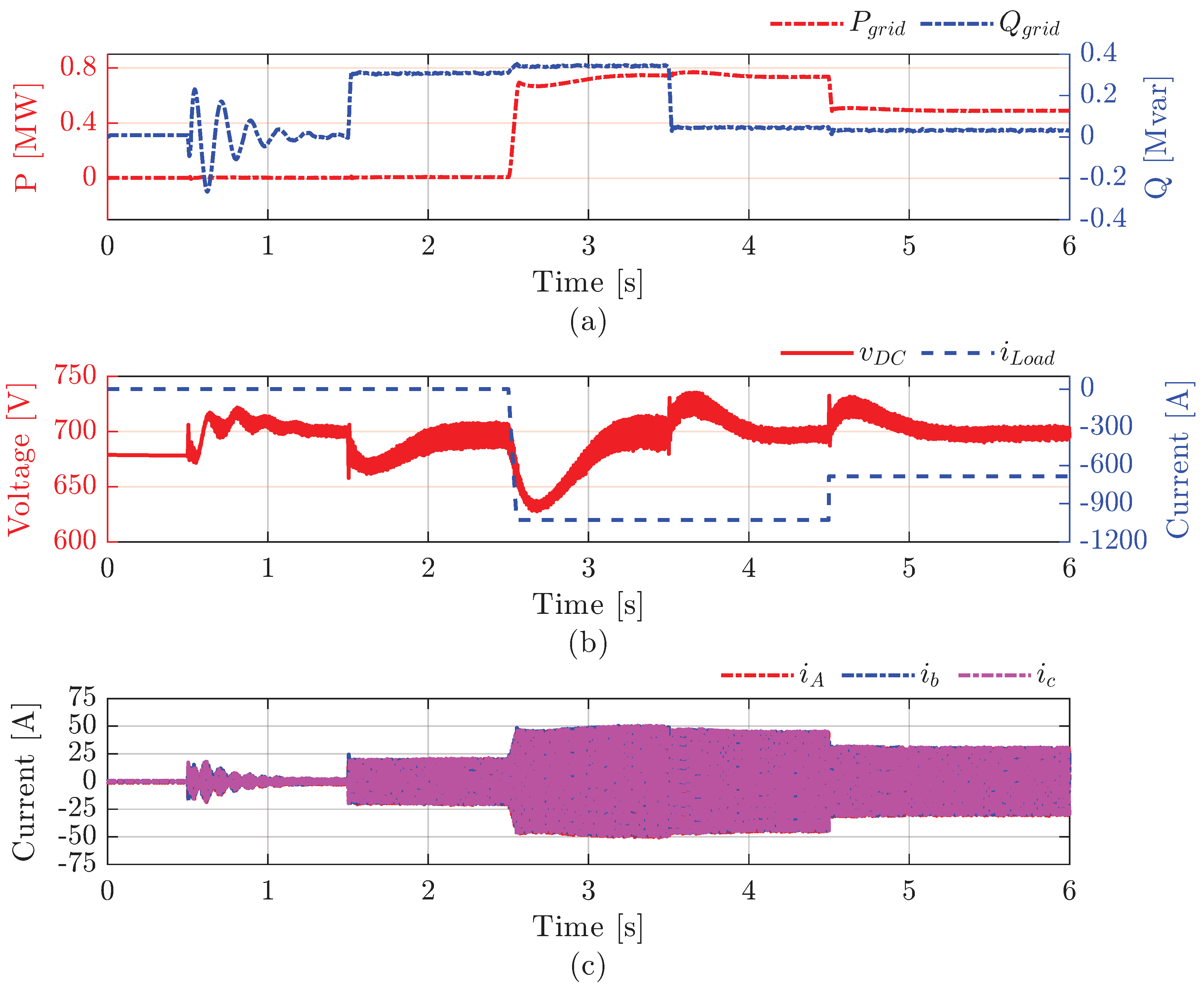
To evaluate the behavior of the ZHD converter controllers, simulations were carried out with variations in the reactive power reference, as well as tests involving the abrupt disconnection of a vehicle during full charging. The EV chargers were modeled as current sources. In this way, it is possible to assess the dynamics of the current controllers and the voltage controllers. The simulation sequence is carried out as follows:
  • 0.5 s: control initialization.
  • 1.5 s: reactive power reference set to 300 kvar.
  • 2.5 s: connection of three EV chargers with a ramp profile (demand of 720 kW from the dc link).
  • 3.5 s: reactive power reference set to zero.
  • 4.5 s: step disconnection of one EV charger (demand reduction from 720 kW to 480 kW).
Figure 8 shows the grid powers, the dc-link voltage, the demanded current, and the grid currents throughout the entire simulation period. By observing Figure 8b, when a reactive power demand of 300 kvar is applied, there is a variation in the dc-link voltage, which drops from 700 V to approximately 660 V (a 7% variation). At the moment when the three vehicles are simultaneously connected, the dc-link voltage falls to around 630 V (a 10% variation). When one of the EV chargers is abruptly disconnected, the dc-link voltage rises to about 725 V (a 3.6% variation). A similar variation occurs when the reactive power reference is set to zero. In all cases of dc-link voltage variation, 600 ms was sufficient to return to the setpoint value, corresponding to approximately five times the period of the frequency ω v 2 z h d shown in Table 2. Analyzing Figure 8c, no current spikes are observed during the transitions.
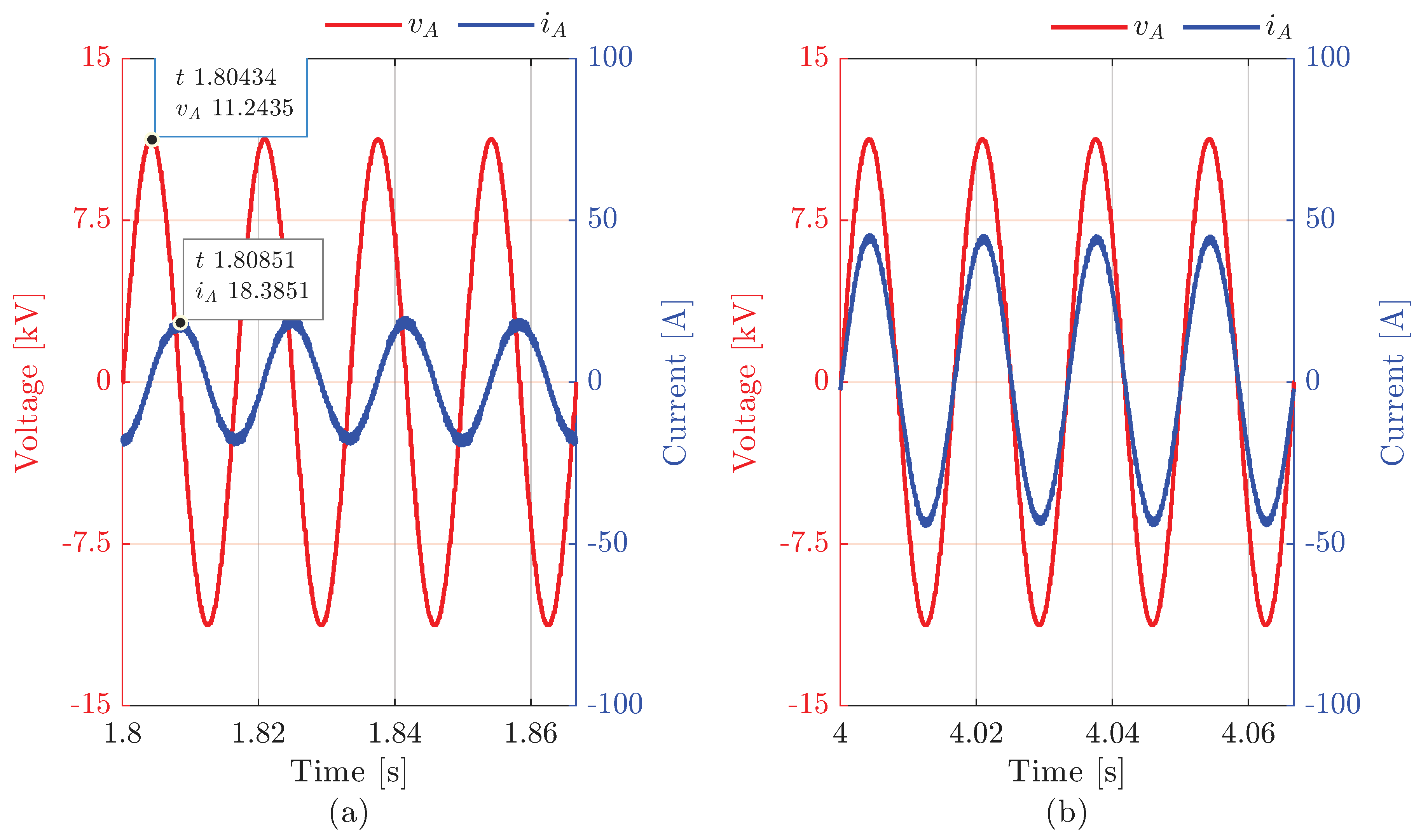
Figure 9 shows the voltage and current in phase A of the grid during the period in which only reactive power is demanded and the period in which only active power is demanded through the fast chargers. By observing Figure 9a, the phase shift between voltage and current is 4.2 ms, which corresponds to approximately 90° of angular displacement. Observing Figure 9b, it can be seen that the voltage and current are in phase, indicating a unity power factor.

5. HIL Results

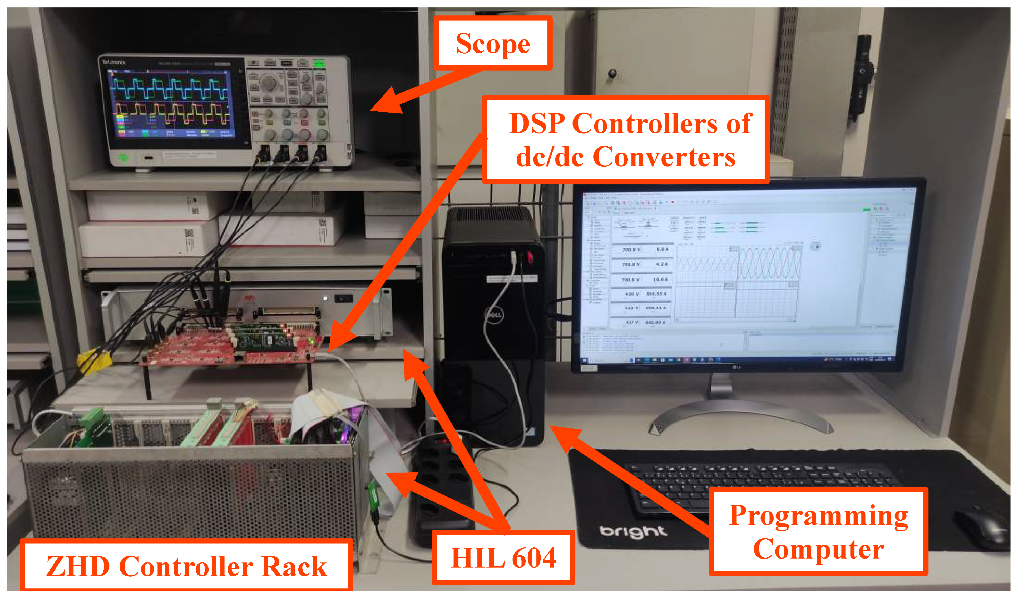
Figure 10 shows the test bench used for the real-time simulation environment. The ZHD controller rack includes a power supply board and a control board equipped with a Texas Instruments TMS320F28335 DSP [47], which is responsible for the voltage and current control of the ZHD converter and operates at a processing frequency of 5.76 kHz. An Altera MAX 10 FPGA [48] performs the SHE PWM and the decoupled double synchronous reference frame phase-locked loop (DDSRF-PLL) [49], operating at a sufficiently high sampling frequency of 250 kHz.
The DSP to FPGA parallel communication, applied solely to ac input stage, is performed through the sending of the modulation index, unsigned 10 bits, and of the synthesized converter voltage angle, signed 13 bits, from the DSP to the FPGA. No special communication protocol is applied.
Each dc/dc converter is controlled by a TMS320F28335 DSP operating at a processing frequency of 20 kHz. Two Typhoon HIL 604 units in parallel run the real-time simulation with a 0.5 μs time step, which is the minimum for this hardware. Three chargers make up the simulated XFC station. The output inductance ( L o u t ) and capacitance ( C o u t ) were defined for a cutoff frequency of 2 kHz, reducing the output current ripple by a factor of 100. The HFT switching frequency and voltage relation was defined based on an already acquired planar transformer from Himag.
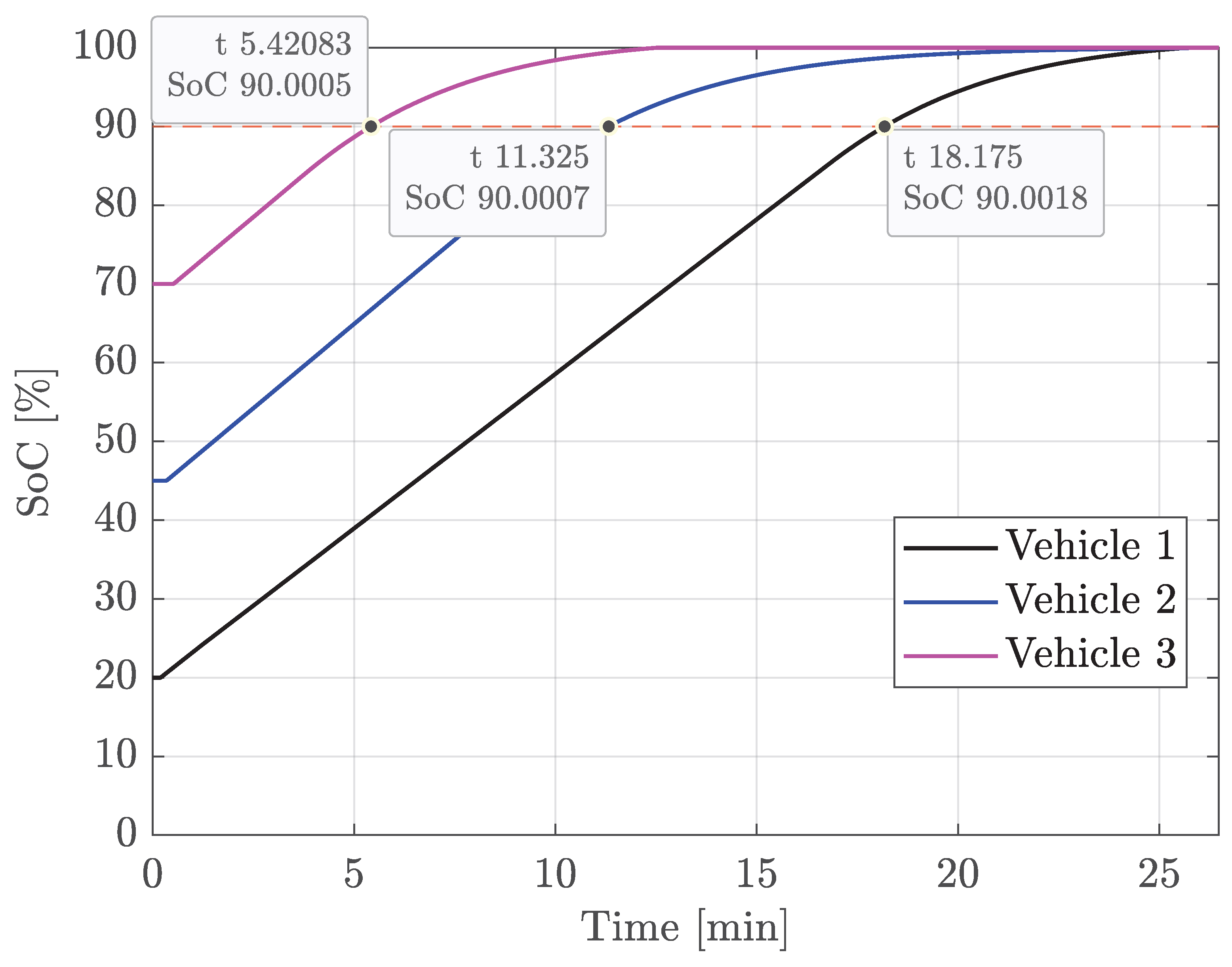
Recharging three vehicles with different battery voltages or SoC makes up the real-time simulation. Vehicle 1 has a battery based on the Audi e-tron GT RS with 800 V architecture and capacity of 93.4 kWh [50] and SoC of 20%. Vehicles 2 and 3 have batteries with the same characteristics shown in Table 4 with SoC of 45% and 70%, respectively.
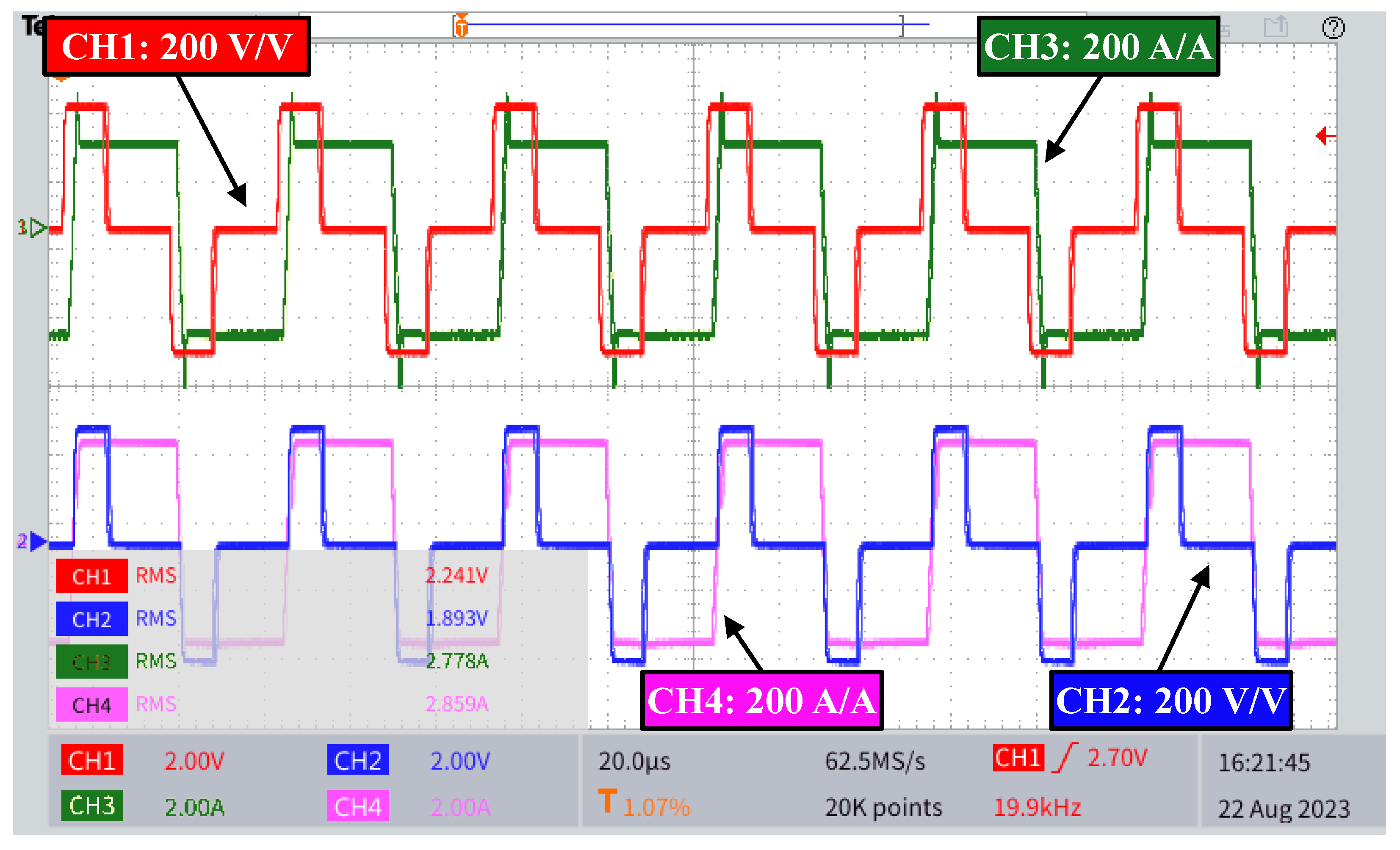
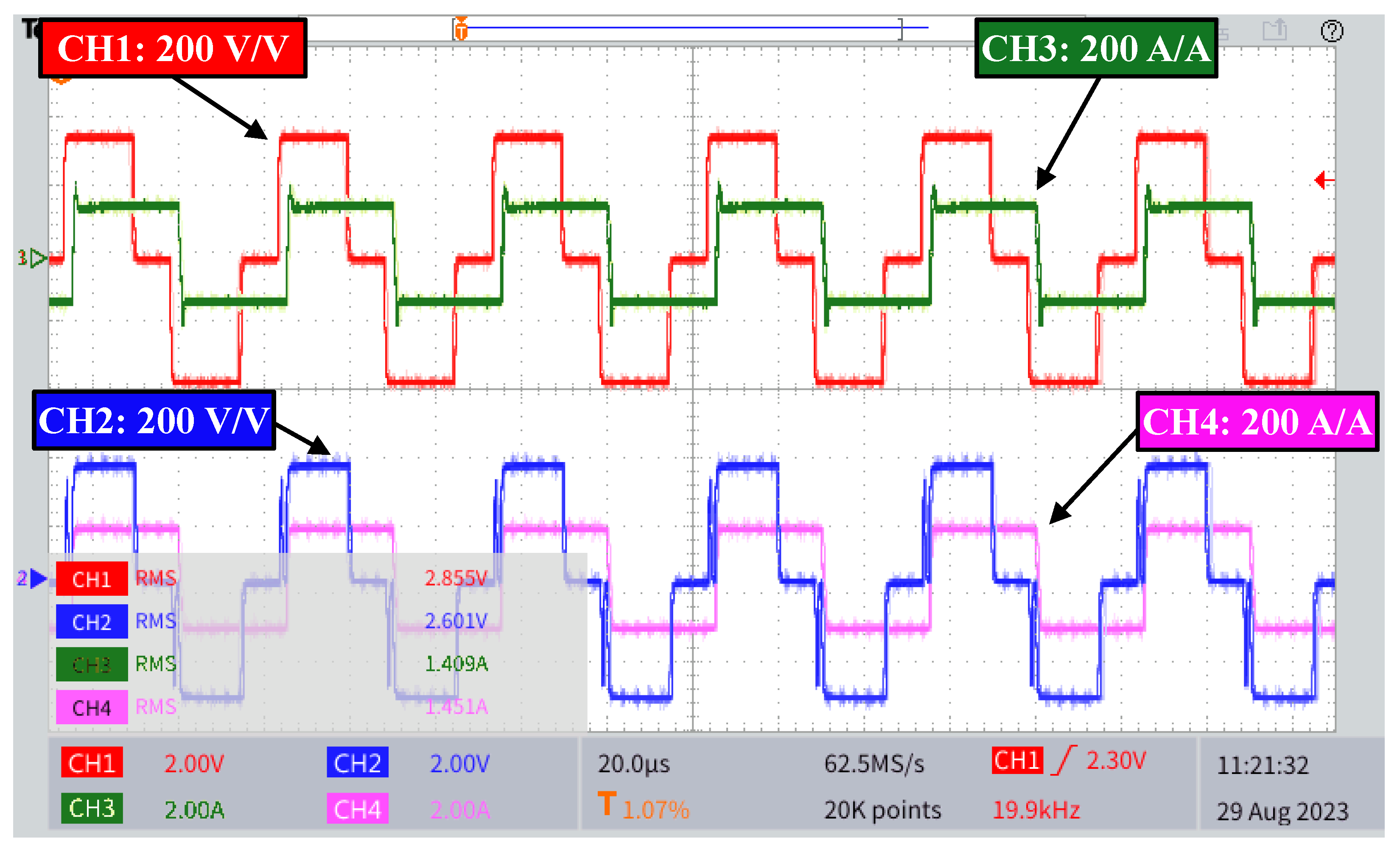
The dc/dc converters support both 400V and 800V architectures. Figure 11 and Figure 12 show the lower SAB HFT voltages and currents for chargers with 400 V and 800 V output, respectively. Figure 12 shows an increase in duty cycle and a reduction in current amplitude compared to the pattern shown in Figure 11.
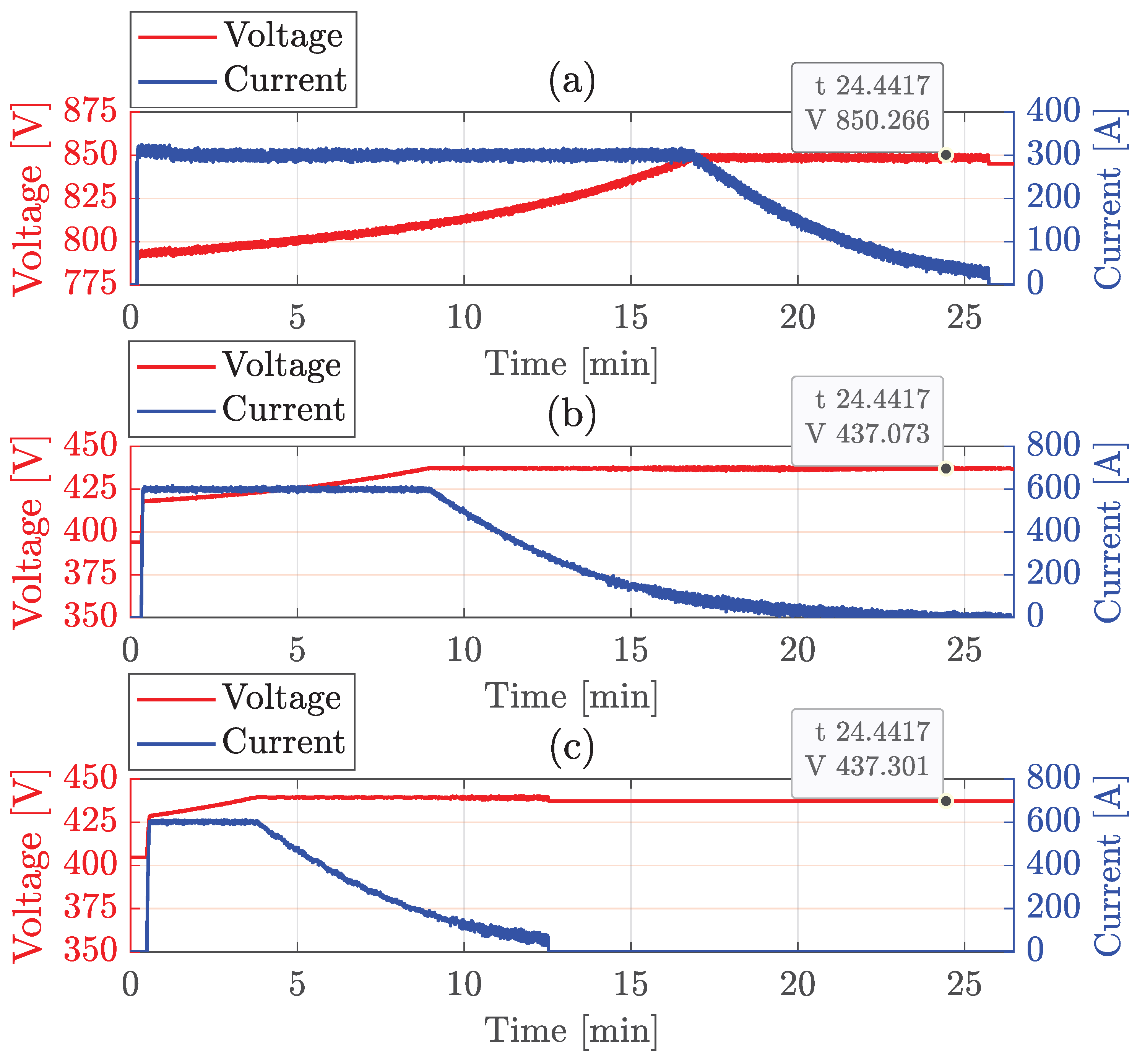
Figure 13 shows the voltage and current in vehicle batteries during recharging. The implemented control performs the CC-CV technique automatically, keeping the currents at max value during the constant current interval and around fully charged voltage during the constant voltage interval. Figure 14 shows the SoC of the batteries during charging. The recharge time from 20% to 90% is 18.2 min, presenting a rate of 3.6 kWh/min.
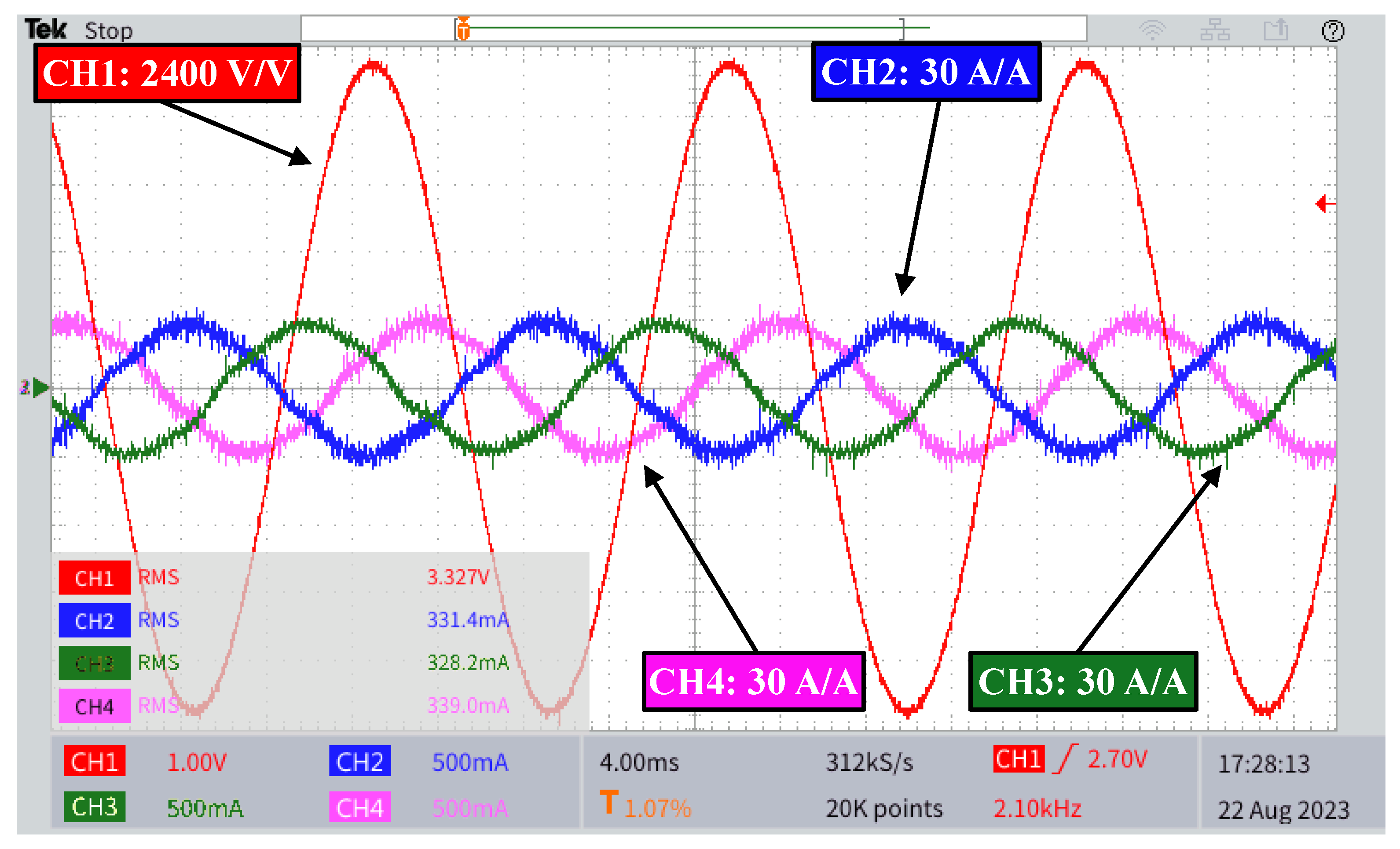
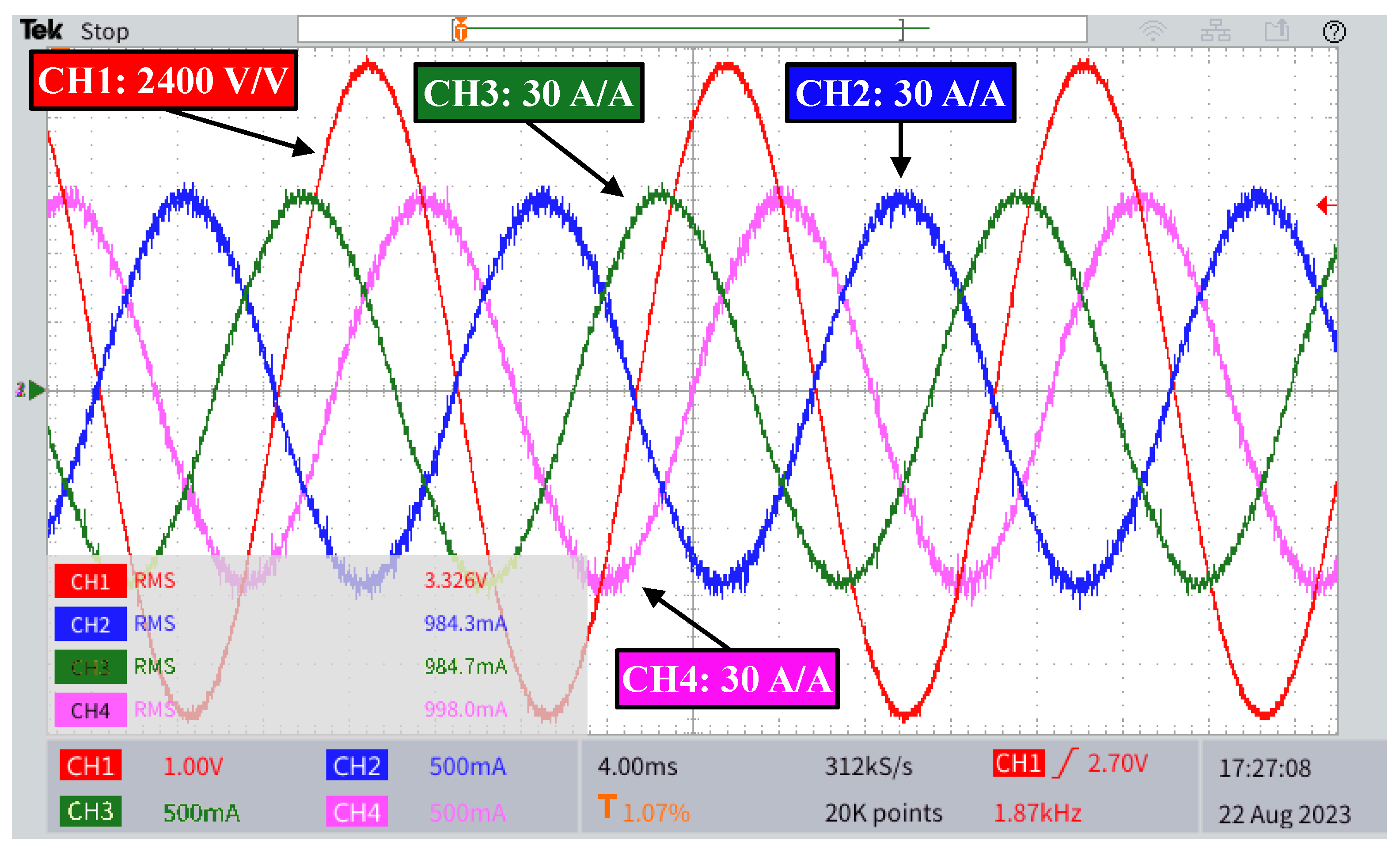
Figure 15 and Figure 16 show the grid voltage phase and currents for recharging one and three vehicles, respectively. Regardless of the number of vehicles, the grid current waveforms are practically sinusoidal, which is corroborated by Table 5, which presents the low TDD of the grid current in the three recharge conditions (max 1.13%).
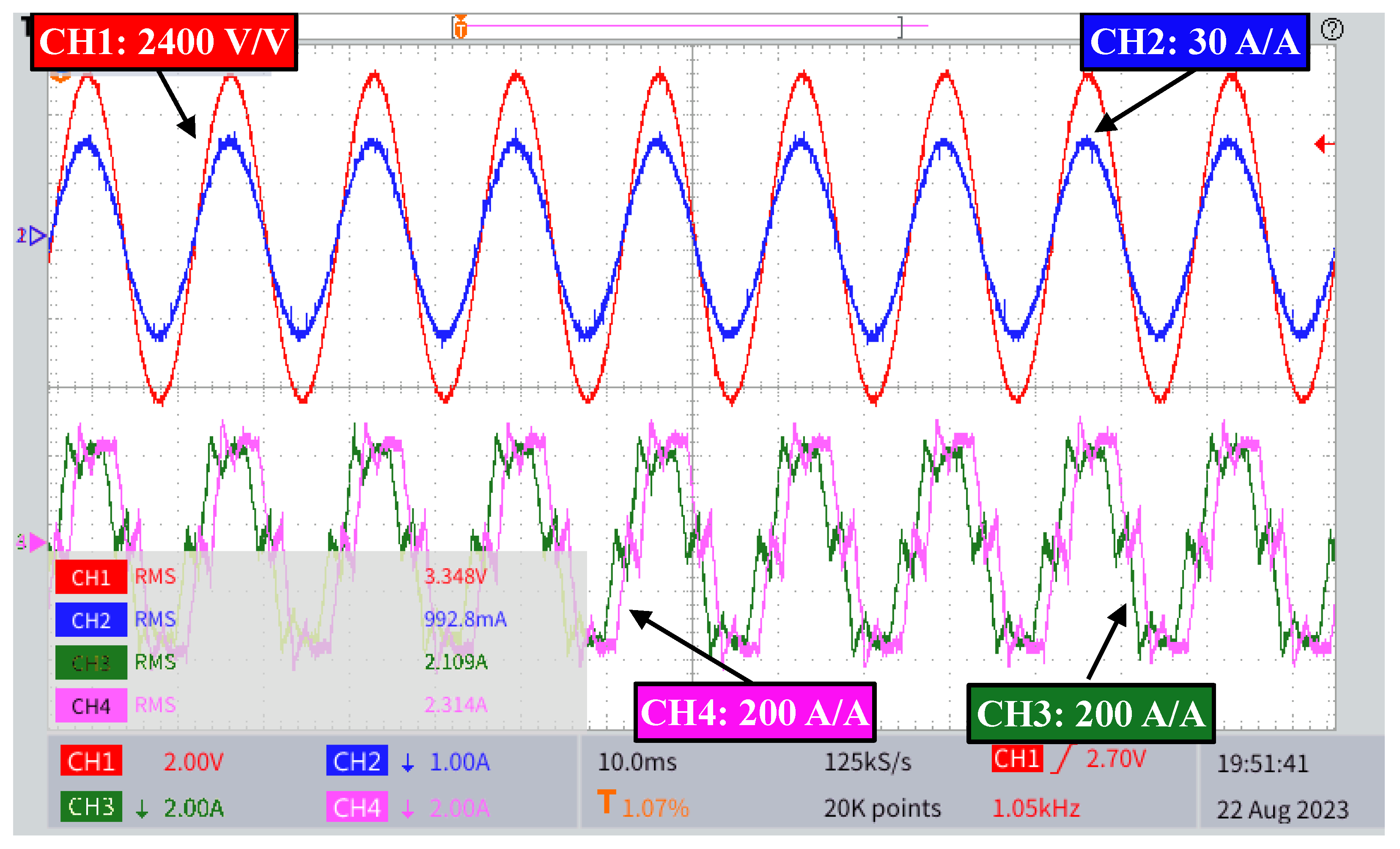
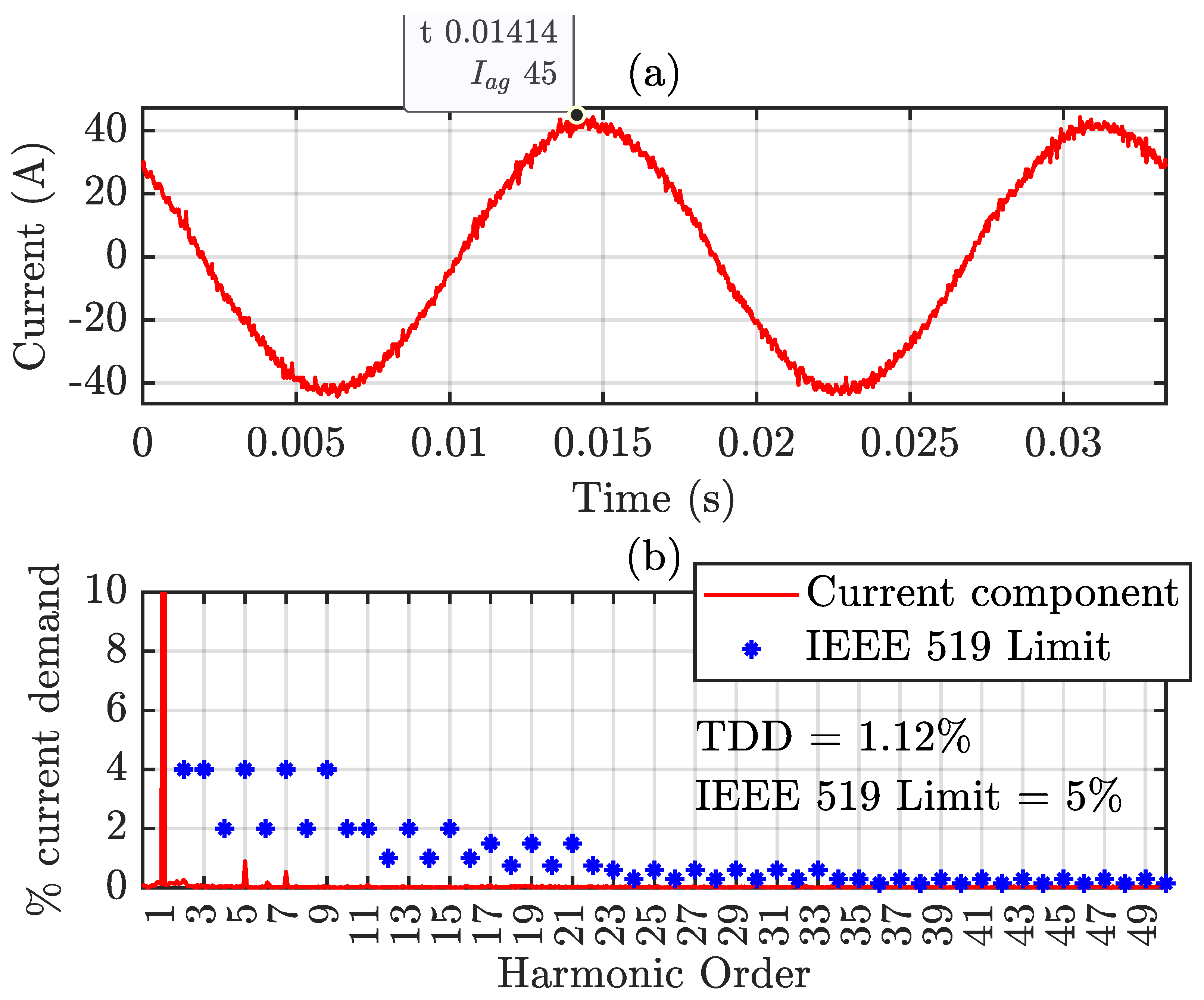
Figure 17 shows the grid voltage and current, and the currents in Δ and wye of transformer secondaries for rated power operation. Secondary currents have high harmonic distortion. However, the harmonic content of the primary current, shown in Figure 18, is practically zero, with amplitudes below the IEEE 519-2022 recommendation.

6. Discussion

The HIL results presented in this paper consistently demonstrate the technical feasibility of the proposed ultra-fast charging station, particularly regarding the operation of the SAB-based dc/dc converter in an IPOS configuration. Waveform analysis shows that the system can supply both 400 V and 800 V batteries without hardware modifications, highlighting its flexibility. At higher voltages, the effective duty cycle increases while current decreases, as shown in Figure 11 and Figure 12, consistent with the converter’s mathematical model; conversely, lower voltages lead to higher current. These findings confirm the suitability of the proposed topology for different electric vehicle architectures while enabling the use of lower voltage-rated semiconductors, reducing system cost and complexity.
Regarding the charging process, the results confirm the effectiveness of the classical CC–CV strategy for lithium-ion batteries. The curves clearly show the transition from current limiting to voltage regulation, as shown in Figure 13. A charging time of about 18.2 min (20% to 90% SOC) at 3.6 kWh/min indicates suitability for ultra-fast applications, while also demonstrating the stability and robustness of the control strategy under varying conditions.
TDD remains around 1.1% under different charging conditions, as shown in Table 5, well below the 5% limit set by IEEE 519. The current waveforms are nearly sinusoidal, regardless of the number of vehicles charging simultaneously. This demonstrates system robustness to load variations and confirms the effectiveness of the ZHD converter in ensuring high power quality without capacitive filters.
Although the voltage THD is expected to vary in accordance with the system impedance, the current TDD is not prone to such variations, as was already demonstrated in [51], where a grid-connected ZHD converter was simulated under two conditions of Short Circuit Ratio (SCR)— S C R = 1 and S C R = 5 —with different types of linear and nonlinear loads, without significant changes in power quality.
Another key contribution is the proposed unified control for the ZHD converter. Unlike individual control, a single modulation index ensures current balance in the transformer secondaries, preserving harmonic cancellation. The results confirm that this strategy is crucial to achieving the low distortion levels, highlighting that performance depends not only on the topology but also on a well-designed control implementation.
Validation through real-time HIL simulation adds reliability to the results. The DSP/FPGA implementation, combined with a small time step, captures practical effects such as delays, discretization, and computational limits, bringing the results closer to the actual operation. Although not a full experimental validation, HIL represents an advanced verification stage, enhancing the proposal credibility.
Despite the promising performance and power quality, some limitations remain. The study lacks experimental hardware validation, leaving aspects such as real losses, thermal behavior, and electromagnetic interference (EMI) unaddressed. In addition, system efficiency is not analyzed in detail, which is critical for high-power applications. Scalability to a larger number of chargers is also not explored, though it could be addressed with a higher-power ZHD converter design.

7. Conclusions

The proposed XFC station is able to fulfill simultaneously the needs of galvanic isolation among all its ports, controlled charging of multiple vehicles and grid power quality with no power electronics at the medium-voltage grid side. Additionally, it provides room for implementation of local DERs and energy storage systems and can be used to support the grid with reactive power, if desired.
HIL results demonstrate the system’s ability to operate with multiple vehicles simultaneously, even with different states of charge and voltage levels. Grid currents remain sinusoidal regardless of the number of active chargers, highlighting the scalability and modularity of the proposed architecture. Each dc/dc converter operates independently on the vehicle side, while the input stage maintains global power quality control, making the solution suitable for real multiport charging stations.
The feasibility of the control system is demonstrated in HIL, showing a system capable of charging multiple vehicles with different characteristics while drawing practically sinusoidal currents from the grid. The HIL results showed a maximum current THD of 1.13% under all three charging conditions, which is below the 5% limit specified in IEEE 519-2022. Thus, the proposed XFC station complies with the requirements of IEEE 519-2022, IEEE 2030.1.1-2017, and UL 2202 standards, making it a viable alternative for XFC stations with multiple vehicle chargers.
Future work includes the experimental validation of the entire station architecture, as well as the analysis of the efficiency and EMI levels of the SAB converter under different operating conditions.

Author Contributions

Conceptualization, D.A.d.L.B., T.M.P., I.A.P. and B.J.C.F.; methodology, D.A.d.L.B., T.M.P., I.A.P. and B.J.C.F.; software, D.A.d.L.B. and T.M.P.; validation, D.A.d.L.B. and T.M.P.; formal analysis, D.A.d.L.B. and T.M.P.; investigation, D.A.d.L.B. and T.M.P.; resources, I.A.P. and B.J.C.F.; data curation, D.A.d.L.B.; writing—original draft preparation, D.A.d.L.B. and T.M.P.; writing—review and editing, D.A.d.L.B., T.M.P., I.A.P. and B.J.C.F.; visualization, D.A.d.L.B., T.M.P., I.A.P. and B.J.C.F.; supervision, I.A.P. and B.J.C.F.; project administration, B.J.C.F.; All authors have read and agreed to the published version of the manuscript.

Funding

This work was carried out with the support of the Coordenação de Aperfeiçoamento de Pessoal de Nível Superior–Brasil (CAPES)–Finance Code 001, and in part by Conselho Nacional de Desenvolvimento Científico e Tecnológico (CNPq), and in part by the Minas Gerais state government agency Fundação de Amparo à Pesquisa do Estado de Minas Gerais (FAPEMIG).

Data Availability Statement

The original contributions presented in this study are included in the article. Further inquiries can be directed to the corresponding author.

Conflicts of Interest

The authors declare no conflicts of interest.

Abbreviations

The following abbreviations are used in this manuscript:
BESSBattery energy storage system
DABDouble Active Bridge
DERDistributed Energy Resources
DDSRF-PLLDecoupled double synchronous reference frame phase-locked loop
DSPDigital Signal Processor
FPGAField-Programmable Gate Array
HFTHigh-frequency transformer
HILHardware-in-the-loop
IPOSInput-parallel output-series
LUTLook-up table
PLLPhase-locked loop
SABSingle Active Bridge
SHE PWMSelective harmonic elimination pulse width modulation
SiCSilicon carbide
SoCState of charge
TDDTotal demand distortion
VSCVoltage source converter
VTFVirtual Transformer Filtering
XFCExtreme fast charging
ZHDZero Harmonic Distortion

References

  1. United Nations Framework Convention on Climate Change—UNFCCC. Conference of the Parties (COP). Available online: https://unfccc.int/process/bodies/supreme-bodies/conference-of-the-parties-cop (accessed on 26 February 2026).
  2. Scania. Scania Battery Electric Truck. Available online: https://www.scania.com/group/en/home/products-and-services/trucks/battery-electric-truck.html (accessed on 26 February 2026).
  3. Scania. Scania LOW FLOOR—Scania Citywide. Available online: https://www.scania.com/group/en/home/products-and-services/buses-and-coaches.html (accessed on 26 February 2026).
  4. Lajunen, A.; Sainio, P.; Laurila, L.; Pippuri-Mäkeläinen, J.; Tammi, K. Overview of Powertrain Electrification and Future Scenarios for Non-Road Mobile Machinery. Energies 2018, 11, 1184. [Google Scholar] [CrossRef]
  5. Federal Highway Administration—U.S. Departament of Transportation. National Electric Vehicle Infrastructure Formula Program. Available online: https://afdc.energy.gov/laws/12744 (accessed on 26 February 2026).
  6. IEEE Std 519-2022; IEEE Standard for Harmonic Control in Electric Power Systems. IEEE: Piscataway, NJ, USA, 2022. [CrossRef]
  7. IEEE Std 2030.1.1-2021; IEEE Standard for Technical Specifications of a DC Quick and Bidirectional Charger for Use with Electric Vehicles. IEEE: Piscataway, NJ, USA, 2022. [CrossRef]
  8. Iyer, V.M.; Gulur, S.; Gohil, G.; Bhattacharya, S. An Approach Towards Extreme Fast Charging Station Power Delivery for Electric Vehicles with Partial Power Processing. IEEE Trans. Ind. Electron. 2020, 67, 8076–8087. [Google Scholar] [CrossRef]
  9. Abarzadeh, M.; Khan, W.A.; Weise, N.; Al-Haddad, K.; EL-Refaie, A.M. A New Configuration of Paralleled Modular ANPC Multilevel Converter Controlled by an Improved Modulation Method for 1 MHz, 1 MW EV Charger. IEEE Trans. Ind. Appl. 2021, 57, 3164–3178. [Google Scholar] [CrossRef]
  10. Monteiro, V.; Ferreira, J.C.; Nogueiras Meléndez, A.A.; Couto, C.; Afonso, J.L. Experimental Validation of a Novel Architecture Based on a Dual-Stage Converter for Off-Board Fast Battery Chargers of Electric Vehicles. IEEE Trans. Veh. Technol. 2018, 67, 1000–1011. [Google Scholar] [CrossRef]
  11. Drobnic, K.; Grandi, G.; Hammami, M.; Mandrioli, R.; Ricco, M.; Viatkin, A.; Vujacic, M. An Output Ripple-Free Fast Charger for Electric Vehicles Based on Grid-Tied Modular Three-Phase Interleaved Converters. IEEE Trans. Ind. Appl. 2019, 55, 6102–6114. [Google Scholar] [CrossRef]
  12. UL 2202; UL 2202 Standard for Safety: DC Charging Equipment for Electric Vehicles. Underwriters Laboratories: Northbrook, IL, USA, 2022.
  13. Tu, H.; Feng, H.; Srdic, S.; Lukic, S. Extreme Fast Charging of Electric Vehicles: A Technology Overview. IEEE Trans. Transp. Electrif. 2019, 5, 861–878. [Google Scholar] [CrossRef]
  14. Safayatullah, M.; Elrais, M.T.; Ghosh, S.; Rezaii, R.; Batarseh, I. A Comprehensive Review of Power Converter Topologies and Control Methods for Electric Vehicle Fast Charging Applications. IEEE Access 2022, 10, 40753–40793. [Google Scholar] [CrossRef]
  15. IEC 62955:2018; Residual Direct Current Detecting Device (RDC-DD) to Be Used for Mode 3 Charging of Electric Vehicles. International Electrotechnical Commission: Geneva, Switzerland, 2018.
  16. IEC 61851-1:2017; Electric Vehicle Conductive Charging System—Part 1: General Requirements. International Electrotechnical Commission: Geneva, Switzerland, 2017.
  17. Wang, J.; Zhang, Y.; Elshaer, M.; Perdikakis, W.; Yao, C.; Zou, K.; Xu, Z.; Chen, C. Nonisolated Electric Vehicle Chargers: Their Current Status and Future Challenges. IEEE Electrif. Mag. 2021, 9, 23–33. [Google Scholar] [CrossRef]
  18. Vasiladiotis, M.; Rufer, A. A Modular Multiport Power Electronic Transformer with Integrated Split Battery Energy Storage for Versatile Ultrafast EV Charging Stations. IEEE Trans. Ind. Electron. 2015, 62, 3213–3222. [Google Scholar] [CrossRef]
  19. Lee, E.S.; Park, J.H.; Kim, M.Y.; Lee, J.S. High Efficiency Integrated Transformer Design in DAB Converters for Solid-State Transformers. IEEE Trans. Veh. Technol. 2022, 71, 7147–7160. [Google Scholar] [CrossRef]
  20. Srdic, S.; Lukic, S. Toward Extreme Fast Charging: Challenges and Opportunities in Directly Connecting to Medium-Voltage Line. IEEE Electrif. Mag. 2019, 7, 22–31. [Google Scholar] [CrossRef]
  21. IEC 60060-1:2010; High-Voltage Test Techniques—Part 1: General Definitions and Test Requirements. International Electrotechnical Commission: Geneva, Switzerland, 2010.
  22. Zhang, J.; Yu, J.; Tang, Y.; Duan, J.; Li, C.; Li, W. Behavior Modeling of Lightning Overvoltage and MOA-based Protection for Floating Ground SST. In 2022 IEEE Transportation Electrification Conference and Expo, Asia-Pacific (ITEC Asia-Pacific); IEEE: Piscataway, NJ, USA, 2022; pp. 1–6. [Google Scholar] [CrossRef]
  23. Tan, L.; Wu, B.; Yaramasu, V.; Rivera, S.; Guo, X. Effective Voltage Balance Control for Bipolar-DC-Bus-Fed EV Charging Station with Three-Level DC–DC Fast Charger. IEEE Trans. Ind. Electron. 2016, 63, 4031–4041. [Google Scholar] [CrossRef]
  24. Benedetto, M.d.; Ortenzi, F.; Lidozzi, A.; Solero, L. Design and Implementation of Reduced Grid Impact Charging Station for Public Transportation Applications. World Electr. Veh. J. 2021, 12, 28. [Google Scholar] [CrossRef]
  25. Brandao, D.A.d.L.; Parreiras, T.M.; Pires, I.A.; Cardoso Filho, B.d.J. Regular Extreme Fast Charging Station for E-buses with Low Current Harmonic Content. Eletrônica Potência 2025, 30, e202533. [Google Scholar] [CrossRef]
  26. Brandāo, D.A.d.L.; Parreiras, T.M.; Pires, I.A.; Filho, B.d.J.C. Extreme Fast Charging Station for Multiple Vehicles with Sinusoidal Currents at the Grid Side. In 2022 IEEE Transportation Electrification Conference and Expo, Asia-Pacific (ITEC Asia-Pacific); IEEE: Piscataway, NJ, USA, 2022; pp. 1–6. [Google Scholar] [CrossRef]
  27. Nakajima, A.; Shimizu, M.; Ohashi, H. Power Loss Limit in Unipolar Switching Devices: Comparison Between Si Superjunction Devices and Wide-Bandgap Devices. IEEE Trans. Electron Devices 2009, 56, 2652–2656. [Google Scholar] [CrossRef]
  28. Swamy, M.M.; Kang, J.K.; Shirabe, K. Power Loss, System Efficiency, and Leakage Current Comparison Between Si IGBT VFD and SiC FET VFD with Various Filtering Options. IEEE Trans. Ind. Appl. 2015, 51, 3858–3866. [Google Scholar] [CrossRef]
  29. Zhao, B.; Song, Q.; Liu, W. Experimental Comparison of Isolated Bidirectional DC–DC Converters Based on All-Si and All-SiC Power Devices for Next-Generation Power Conversion Application. IEEE Trans. Ind. Electron. 2014, 61, 1389–1393. [Google Scholar] [CrossRef]
  30. Sang, Y.; Junyent-Ferré, A.; Green, T.C. Operational Principles of Three-Phase Single Active Bridge DC/DC Converters Under Duty Cycle Control. IEEE Trans. Power Electron. 2020, 35, 8737–8750. [Google Scholar] [CrossRef]
  31. Zeng, B.; Yang, Z.; Yan, S.; Tan, L.; Xie, S. A Novel High Power Factor and Soft Switching SAB-SWISS Rectifier With High-Low-High-Low Modulation and Hybrid Frequency Control. IEEE Access 2024, 12, 185187–185199. [Google Scholar] [CrossRef]
  32. TESMAG. The V4 Supercharger Revolution: Why 2026 Is the Year Charging Finally Caught Up. Available online: https://www.teslaacessories.com/ro/blogs/news/the-v4-supercharger-revolution-why-2026-is-the-year-charging-finally-caught-up (accessed on 28 March 2026).
  33. TESLARATI. Tesla Introduces New Liquid-Cooled Supercharger System. Available online: https://www.teslarati.com/tesla-liquid-cooled-supercharger-cables (accessed on 28 March 2026).
  34. Langer, E. Liquid Cooling for EV Charging—What to Know to Keep Electric Vehicles on the Go. Available online: https://www.cpcworldwide.com/Portals/0/Downloadable-Content/TRM/Literature/Tech-Guides/CPC-Liquid-Cooling-in-Electric-Vehicles.pdf (accessed on 28 March 2026).
  35. Almeida, C.E.; Filho, B.d.J.C. Shifting Resonances in Wind Farms to Higher Frequencies due to TUPF Converters. J. Control Autom. Electr. Syst. 2018, 29, 805–815. [Google Scholar] [CrossRef]
  36. Parreiras, T.M.; Alves, M.H.d.S.; Almeida, C.E.; Silva, S.M.; Filho, B.d.J.C. The True Unit Power Factor Converter with Flexible Arrangement for Battery Energy Systems: Series and Separate DC bus connection. In 2020 IEEE Applied Power Electronics Conference and Exposition (APEC); IEEE: Piscataway, NJ, USA, 2020; pp. 3405–3412. [Google Scholar] [CrossRef]
  37. Brandão, D.A.d.L.; Parreiras, T.M.; Pires, I.A.; Cardoso F., B.d.J. Electric Arc Furnace Reactive Compensation System Using Zero Harmonic Distortion Converter. IEEE Trans. Ind. Appl. 2022, 58, 6833–6841. [Google Scholar] [CrossRef]
  38. Liu, N.; Chen, Q.; Lu, X.; Liu, J.; Zhang, J. A Charging Strategy for PV-Based Battery Switch Stations Considering Service Availability and Self-Consumption of PV Energy. IEEE Trans. Ind. Electron. 2015, 62, 4878–4889. [Google Scholar] [CrossRef]
  39. De Doncker, R.; Divan, D.; Kheraluwala, M. A three-phase soft-switched high-power-density DC/DC converter for high-power applications. IEEE Trans. Ind. Appl. 1991, 27, 63–73. [Google Scholar] [CrossRef]
  40. Timmers, V.; Egea-Àlvarez, A.; Gkountaras, A.; Xu, L. Multi-Objective Optimization and Comparison of DC/DC Converters for Offshore Wind Turbines. IEEE Access 2024, 12, 81236–81251. [Google Scholar] [CrossRef]
  41. Ting, Y.; de Haan, S.; Ferreira, J.A. The partial-resonant single active bridge DC-DC converter for conduction losses reduction in the single active bridge. In 2013 IEEE ECCE Asia Downunder; IEEE: Piscataway, NJ, USA, 2013; pp. 987–993. [Google Scholar] [CrossRef]
  42. Mohan, N.; Undeland, T.M.; Robbins, W.P. Power Electronics: Converters, Applications and Design, 3rd ed.; John Wiley & Sons: Hoboken, NJ, USA, 2003. [Google Scholar]
  43. Lorenz, R.; Lipo, T.; Novotny, D. Motion control with induction motors. Proc. IEEE 1994, 82, 1215–1240. [Google Scholar] [CrossRef]
  44. Dias-Gonzáles, F.; Sumper, A.; Gomis-Bellmunt, O. Energy Storage in Power Systems; Wiley: Hoboken, NJ, USA, 2016. [Google Scholar]
  45. Linden, D.; Reddy, T.B. Handbook of Batteries, 3rd ed.; McGraw-Hill: New York, NY, USA, 2002. [Google Scholar]
  46. Himag. Himag Planar Transformers. Available online: https://www.himag.co.uk (accessed on 26 February 2026).
  47. Texas Instruments. TMS320F2833x, TMS320F2823x Real-Time Microcontrollers. Texas Instruments: Dallas, TX, USA. Available online: https://www.ti.com/lit/ds/symlink/tms320f28335.pdf (accessed on 28 February 2026).
  48. Altera. MAX 10 FPGA. Altera: San Jose, CA, USA. Available online: https://www.altera.com/products/fpga/max/10 (accessed on 28 February 2026).
  49. Rodriguez, P.; Pou, J.; Bergas, J.; Candela, J.I.; Burgos, R.P.; Boroyevich, D. Decoupled Double Synchronous Reference Frame PLL for Power Converters Control. IEEE Trans. Power Electron. 2007, 22, 584–592. [Google Scholar] [CrossRef]
  50. EV Database. Audi e-Tron GT RS. Available online: https://ev-database.org/car/1153/Audi-RS-e-tron-GT (accessed on 26 February 2026).
  51. Ramos, G.V.; Parreiras, T.M.; Zhao, F.; Wang, X.; Filho, B.d.J.C. A Zero Harmonic Distortion Grid-Connected Grid-Forming Converter for Battery Energy Storage System Applications. In 2025 IEEE Applied Power Electronics Conference and Exposition (APEC); IEEE: Piscataway, NJ, USA, 2025; pp. 1615–1621. [Google Scholar] [CrossRef]
Figure 1. Proposed XFC station with ZHD converter [26].
Wevj 17 00215 g001
Figure 2. ZHD converter [26].
Wevj 17 00215 g002
Figure 3. IPOS SAB SiC-based dc/dc converter [26].
Wevj 17 00215 g003
Figure 4. ZHD converter control.
Wevj 17 00215 g004
Figure 5. Asymptotes representing the disturbance–output relationship curve of the ZHD converter: (a) current controller and (b) voltage controller.
Wevj 17 00215 g005
Figure 6. DC/DC converter control schematic.
Wevj 17 00215 g006
Figure 7. Asymptotes representing the disturbance–output relationship curve of the SAB converter: (a) current controller and (b) voltage controller.
Wevj 17 00215 g007
Figure 8. (a) Active and reactive grid power. (b) DC-link voltage and dc load current. (c) Grid currents.
Wevj 17 00215 g008
Figure 9. Voltage and current in phase A of the grid: (a) during the reactive power injection period and (b) during the active power demand period.
Wevj 17 00215 g009
Figure 10. HIL test bench.
Wevj 17 00215 g010
Figure 11. Voltages and currents for lower SAB charging 400 V battery: primary voltage (CH1), secondary voltage (CH2), primary current (CH3) and secondary current (CH4).
Wevj 17 00215 g011
Figure 12. Voltages and currents for lower SAB charging 800 V battery: primary voltage (CH1), secondary voltage (CH2), primary current (CH3) and secondary current (CH4).
Wevj 17 00215 g012
Figure 13. Voltage and current in the battery of vehicles (a) 800 V and 20% SoC (Vehicle 1), (b) 400 V and 45% SoC (Vehicle 2), and (c) 400 V and 70% SoC (Vehicle 3).
Wevj 17 00215 g013
Figure 14. State of charge in vehicle batteries.
Wevj 17 00215 g014
Figure 15. Grid phase A voltage (CH1) and currents in phase A (CH2), phase B (CH3) and phase C (CH4) for one charger.
Wevj 17 00215 g015
Figure 16. Grid phase A voltage (CH1) and currents in phase A (CH2), phase B (CH3) and phase C (CH4) for three chargers simultaneously.
Wevj 17 00215 g016
Figure 17. Grid phase A voltage (CH1) and grid current in phase A (CH2), secondary phase A current in Delta (CH3) and secondary phase A current in wye (CH4) for three chargers simultaneously.
Wevj 17 00215 g017
Figure 18. (a) Grid current in phase A. (b) Harmonic content of current in phase A of the grid. IEEE 519 limit described in [6].
Wevj 17 00215 g018
Table 1. Comparison between proposed topologies for extreme fast charging stations.
Grid-Connected
Converter
DC/DC
Converter
IEEE
2030.1.1?
UL
2202?
IEEE
519?
Diodes/
Switches
Switches
Technology
f sw
(kHz)
Sim./Exp.
Power (kW)
THD i
(%)
Modular ANPC [9]N.M. a0/54 | ✗SiC and Si333 and 0.061000/50N.M.
Parallel two-level [10]Interleaved0/12 | 0/4Si/Si20/20✗/402.0 b
Interleaved [11]InterleavedN.M.0/18 | 0/18Si/Si16/16150/150N.M.
Conventional NPC [23]Three-level6/12 | 4/4Si/Si1.08/2.16240/1.22.46 b/-
Five-level E-type [24]DABding5112/36 | 0/8Si/Si20/40✗/254.7 b
Cascaded H-Bridge [18]DABN.M.0/54 | 0/24Si/SiN.M./N.M.N.M./N.M.N.M.
Cascaded H-Bridge [19]DABN.M.0/6 | 0/12N.M./N.M.10/10250/250N.M.
Proposal: ZHD converterIPOS SAB0/12 | 8/8Si/SiC1.14/201000/2801.13 b/2.29 c,d
a N.M.: Not mentioned. b Simulation results. c Experimental results. d According to [25].
Table 2. ZHD converter controllers adjust.
ParameterCurrent ControllerDC Voltage Controller
d-Axisq-Axis
Poles72 Hz{72, 7.2} Hz{7.2, 0.72} Hz
Proportional47.4 Ω 47.4 Ω 1.03 S
Integral- a2142 Ω · s−14.66 S·s−1
a The integral gain of the d-axis current controller is set to zero, since the integral action is already handled by the upstream dc voltage controller.
Table 3. SAB dc/dc converter controllers adjust.
ParameterCurrentVoltage
Poles{2, 0.2} kHz{1.7, 0.33} mHz
Proportional3.92 Ω 61.8 S
Integral a4927 Ω · s−10.13 S·s−1
Anti-windup time constant ( T t )-600 s
a The current controller integral gain is set to zero when the voltage controller is not saturated, as the integral action is already performed by the upstream voltage controller.
Table 4. System parameters.
ElementSymbolParameterValue
Grid V g Voltage (kV)13.8
Frequency (Hz)60
Impedance ( Ω ) 0.95 + j 0.19
ZHD Transformer Nominal Power (kVA)900
Primary Voltage (kV)13.8
Secondaries Voltage (V)480
ConnectionDd0y1
ZHD reactors L Δ Δ reactor (mH)0.27
L Y Y reactor (mH)0.24
ZHD VSC Topology2L
ZHD dc link Voltage (V)700
C d c Capacitance (mF)25.3
High-Frequency Transformer Transformer Ratio1
Nominal Input Voltage [V]1000
Nominal Output Voltage [V]1000
f s w Nominal Frequency [kHz]20
Primary Leakage Inductance [μH]0.9
L s Secondary Leakage Inductance [μH]0.9
DC/DC Converter Power [kW]240
Input Voltage [V]700
Max Output Current [A]600
L o u t Output Inductance [μH]312
C o u t Output Capacitance [μF]21
Battery Nominal Voltage [V]375
Capacity [kWh]103
C b a t t Capacitance Model [F]5902
Table 5. Current TDD for HIL simulation.
Power Quality IndexNumber of Recharging VehiclesIEEE Std 519-2022 Limit
123
TDD1.13%1.09%1.12%5%
Disclaimer/Publisher’s Note: The statements, opinions and data contained in all publications are solely those of the individual author(s) and contributor(s) and not of MDPI and/or the editor(s). MDPI and/or the editor(s) disclaim responsibility for any injury to people or property resulting from any ideas, methods, instructions or products referred to in the content.