1. Introduction
Flux-reversal machines are a classic representative of stator-permanent magnet doubly salient machines. With windings and permanent magnets installed on one side of the stator and a salient-pole rotor structure without windings, they exhibit the advantages of high power density, fast response, and strong fault tolerance. Such machines show considerable prospects in electric vehicles, aerospace, and industrial automation [
1].
Traditional flux-reversal machines struggle to achieve high-efficiency operation over a wide speed range and suffer from severe core saturation due to excessive local magnetic loading, low torque density, and large torque ripple. The large torque ripple degrades low-speed stability and positioning accuracy. Moreover, due to stator-rotor eccentricity and asymmetric pole-slot combinations [
1,
2], the air-gap magnetic field is severely distorted, inducing severe vibration and noise that greatly affects operational stability. The rich harmonics in the magnetic field also lead to increased iron losses. This paper proposes a novel topology of a stator-segmented dual-sequence permanent magnet flux-reversal machine equipped with dual windings. By synergistically incorporating segmented stator modules, dual permanent magnet arrays, and independent dual-winding structures, the proposed machine achieves improved torque performance, smoother operation, and enhanced fault tolerance, thereby extending its potential in high-end applications.
This design modifies the integral stator structure of conventional permanent magnet flux-reversal machines by segmenting the stator into modular sections, where adjacent segments are connected by permanent magnets. This arrangement makes the magnetic circuits between stator modules mutually independent. In the event of a fault in a single stator module, only the corresponding circuit needs to be disconnected for maintenance, significantly reducing repair costs. Meanwhile, the other stator segments can continue operating normally, avoiding the total shutdown caused by local stator faults in conventional structures and greatly enhancing the stability and fault tolerance of the machine. By employing permanent magnets on both sides of each stator segment, iron losses are reduced and magnetic circuits are shortened. The permanent magnet connections between stator segments largely cancel the flux density harmonics, further suppressing unbalanced magnetic pull and accelerating magnetic field response. Since the number of stator segments is not fixed, it can be determined according to different application scenarios and requirements, improving the engineering flexibility of the machine.
Departing from the single-winding configuration of conventional flux-reversal permanent magnet machines, the proposed machine adopts two independent windings: the power-fault-tolerant winding (three-phase connected fault-tolerant winding) contributes to high electromagnetic torque, while the independent excitation regulation winding compensates for air-gap distortion and suppresses torque ripple. This extends the flux-weakening speed range and enables adjustable air-gap magnetic field intensity.
Domestic scholars have conducted multi-dimensional research on stator segmentation, involving topological innovation, control strategies, and performance simulation. In 2010, Lin Lingyan analyzed the magnetic field distribution, static force characteristics, and dynamic starting process of segmented permanent magnet linear synchronous motors using steady-state and time-stepping finite element models, with experimental verification [
3]. In 2016, Kong Longtao et al. proposed a position-sensorless control scheme based on a model reference adaptive system for magnetic circuit complementary modular flux-switching permanent magnet linear motors. Simulation and experimental results demonstrate low speed ripple and strong robustness [
4]. In 2022, Su Peng et al. presented an axial modular flux-reversal machine topology with toroidal windings and an axial modular structure, explaining its operating mechanism via air-gap field modulation theory and verifying its advantages of high torque density and low torque ripple compared to conventional models [
5]. In 2025, Wang Yunkun et al. investigated multi-power-supply stator-segmented permanent magnet linear synchronous motors, proposing a general calculation method for power supply switching control and electromagnetic thrust synthesis, which was validated as being effective for both seamless and gapped stator splicing [
6]. These studies laid a solid foundation for modular stator research.
Combining the high power density of permanent magnet machines and the adjustable magnetic field of electrically excited machines, hybrid excitation machines have become a research hotspot in China. In 2020, Zhang Zhuoran et al. reviewed the structural characteristics and flux regulation mechanisms of hybrid excitation synchronous machines and field-modulated machines, summarizing universal design methods and multi-dimensional collaborative control strategies for different applications and forecasting their broad prospects in transportation electrification [
7]. In 2023, Wang Jinyu proposed a DC-biased dual-permanent-magnet hybrid excitation machine topology with dual permanent magnet excitation and integrated stator windings, revealing the principles of flux regulation and torque generation via air-gap field modulation theory and optimizing torque performance and flux regulation capability [
8]. In 2022, Wang Yukun designed a modular stator staggered-rotor hybrid excitation machine based on amorphous alloy, analyzing its electromagnetic characteristics via 3D finite element and equivalent magnetic network methods and verifying the effect of amorphous alloy in reducing iron losses. Wang Jiabing proposed hybrid excitation flux-switching machines and DC-biased dual-permanent-magnet hybrid excitation machines, improving torque density and flux regulation through multi-objective optimization [
9]. In 2023, Pang Xianwen established a 3D magnetic network model for modular stator hybrid excitation machines, investigating flux regulation performance and control methods under no-load and loaded conditions, and verified the superiority of the proposed minimum copper loss control strategy through simulation [
10]. These studies effectively addressed the problem of uncontrollable magnetic fields in conventional permanent magnet machines and facilitated topological innovation and performance optimization of hybrid excitation machines.
The combination of dual-winding and flux-reversal machines holds significant application value in special vehicles, new energy vehicles, and other fields. Domestic scholars have conducted comprehensive research on their control strategies, engineering applications, and modeling methods. In 2017, Lu Binglin et al. compared the performance of stator-permanent magnet and rotor-permanent magnet hybrid stepping motors, finding that the stator-permanent magnet type featured a simple rotor structure, high mechanical strength, large torque density, and easy permanent magnet heat dissipation, and verified the feasibility of the operating principle through a prototype [
11]. In 2020, Liu Yiping addressed the winding switching issue of dual-winding permanent magnet synchronous motors by proposing a three-phase step-by-step synchronous switching strategy and a method to determine the optimal switching region. Simulation and experimental results confirmed smooth winding switching [
12]. Also in 2020, Pan Daisong et al. developed high-power dual-winding permanent magnet synchronous motors for transportation applications, effectively reducing energy consumption in heavy-duty vehicles [
13]. These studies laid the necessary foundation for the integrated application of dual-winding and flux-reversal machines.
In recent years, foreign scholars have also conducted extensive research on flux-reversal machines, focusing on improving torque density, suppressing torque ripple, and expanding application scenarios. For topology optimization, innovative stator structures such as alternate poles [
14], auxiliary teeth [
15,
16], and V-shaped flux concentration [
17] have been proposed. Genetic algorithms [
14,
18] combined with multi-objective optimization [
16,
17,
18] have been used for parameter tuning to enhance torque output and efficiency. To reduce torque ripple, researchers optimized the rotor geometry [
18] and improved air-gap flux density distribution through concave stator poles and auxiliary teeth [
16]. Advanced strategies such as model predictive control [
19] have been integrated into special configurations including axial flux [
18], transverse flux linear [
19], and bearingless [
20] machines, enabling the improved machines to suit high-performance applications such as electric vehicle in-wheel drives [
14,
15] and long-stroke direct drives [
20].
These domestic and international studies have laid a solid and diverse foundation for the development of machine theory, providing ample practical references for applications in petroleum, chemical engineering, electric vehicles, intelligent manufacturing, and other fields. They drive the continuous advancement of machine theory and practice and serve as key theoretical guidance and design benchmarks for the motor design case study in this paper. Similarly, this method also provides a reliable theoretical basis for the proposed motor topology design.
2. Design Scheme
2.1. Motor Structure
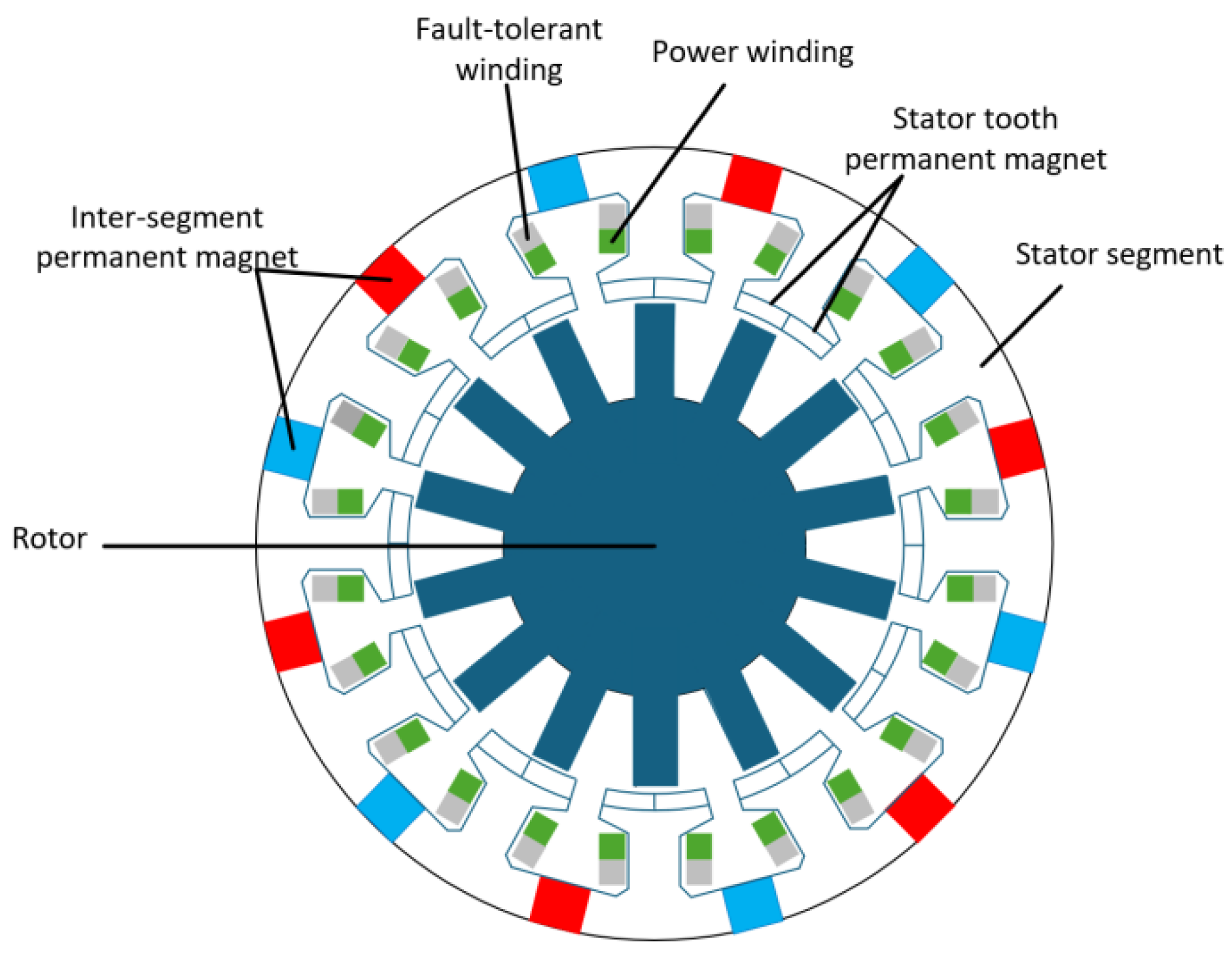
The stator-segmented dual-winding dual-sequence permanent magnet flux-reversal machine proposed in this paper (
Figure 1) adopts a segmented-stator, dual-winding, and dual-sequence permanent magnet structure.
The stator-segmented dual-winding dual-permanent-magnet flux-reversal machine employs the cooperative operation of the power winding and the fault-tolerant winding, enabling the machine to flexibly adjust the fundamental amplitude of the air-gap magnetic field, thereby achieving the flux-weakening extension effect. The rotor surface is nitrided to form a nitrided layer, which effectively improves the mechanical strength and wear resistance of the rotor. This enhances the operational stability of the machine and reduces the later maintenance cost.
Instead of using the conventional integral monolithic stator, a segmented stator structure is adopted so that the windings correspond to the stator segments one-to-one with independent magnetic circuits. A fault occurring in a single stator segment will not spread to the entire stator, solving the problem that a local stator fault in the traditional structure leads to the shutdown of the whole machine and greatly improving the operational stability and fault tolerance of the motor. Meanwhile, thanks to the flexible assembly of stator segments, the machine can be equipped with an appropriate number of segments according to the application requirements, which reduces the operation cost, improves the application flexibility, and expands the applicable scope of the machine.
By adopting two sequences of permanent magnets, the inter-segment permanent magnets are added on the basis of the original stator-tooth permanent magnets, so the harmonic magnetic fields of the machine are mutually canceled. This effectively reduces the distortion rate of the air-gap flux density, significantly suppresses the unbalanced magnetic pull and torque ripple, and solves the problems of easy magnetic field distortion and poor operational stability in the single-sequence permanent magnet structure. A single permanent magnet is mounted on each side of the same stator segment, with opposite polarities between the two permanent magnets. As a result, the magnetic flux generated by the permanent magnets follows the path from the stator segment to the air gap and then to the rotor poles, which increases the amplitude of the air-gap flux density wave and greatly improves the torque density.
The machine proposed in this paper replaces the conventional continuous monolithic stator with a segmented stator model, where adjacent stator segments are connected by NdFeB permanent magnets. By adopting the segmented stator structure instead of the integral one, the windings are in one-to-one correspondence with the stator segments and are magnetically independent.
With the segmented stator structure, when a fault occurs in the winding on a single stator segment, the machine can maintain output instead of being completely shut down. This solves the problem that a local fault in the integral stator structure causes the whole machine to stop running, and greatly improves the operational stability of the motor. Furthermore, the number of stator segments can be determined according to different application scenarios, which extends the application fields and improves the operational flexibility of the machine.
2.2. Innovative Analysis of Motor Design
Compared to the existing stator-segmented flux-reversal machines, the design scheme proposed in this paper has achieved innovations and improvements in terms of windings, magnetic circuits, and manufacturing processes.
In this motor, load-power windings and load fault-tolerant windings are mounted on the segmented stator, with the two sets of independent windings corresponding one-to-one to the stator segments. If a single winding malfunctions, the other can be quickly switched in to maintain the motor’s continuous output without shutdown, which theoretically improves the fault tolerance of the motor.
This motor adopts a dual permanent magnet array structure consisting of inter-tooth permanent magnets and inter-module permanent magnets on the stator. By leveraging the reverse effect of the two permanent magnet arrays and the magnetomotive force superposition of the dual windings, precise regulation of the magnetic flux density in stator teeth is achieved. Meanwhile, the air-gap magnetic field distribution is optimized, which significantly improves the sinusoidal degree of the air-gap magnetic flux density and ensures the stable operation of the motor.
In terms of manufacturing technology, this motor features a modular design integrating dual windings with a segmented stator, which enables segmented processing, independent wire embedding, and modular assembly of the motor. Theoretically, this design mitigates the issues of high wire embedding difficulty for single windings and high post-operation maintenance costs associated with conventional stator-segmented flux-reversal machines.
2.3. Design of Dual-Sequence Permanent Magnets
The dual-sequence permanent magnets are divided into stator-tooth permanent magnets and inter-segment connecting permanent magnets, both of which are made of NdFeB. The permanent magnets at the stator teeth are regarded as the main permanent magnets, while the connecting permanent magnets between stator segments are used as auxiliary permanent magnets.
According to the formula for the spatial distribution of the magnetomotive force (MMF) of the permanent magnets between stator teeth along the inner surface of the stator, it can be obtained that
In Equation (1), Ftpm is the magnetomotive force (MMF) of the stator-tooth permanent magnets on the stator central tooth, Pe is the number of excitation pole pairs, and θs is the spatial position angle of the stator.
According to the formula for the spatial distribution of the magnetomotive force (MMF) of the inter-segment permanent magnets along the inner surface of the stator, it can be obtained that
In Equation (2), Fipm is the fundamental amplitude of the magnetomotive force (MMF) of the inter-module permanent magnets.
According to Equations (1) and (2), the magnetomotive forces of the main and auxiliary permanent magnets can be calculated, and the result can be obtained as
After combining using trigonometric identities, the total electromotive force can be expressed as
Equation (5) gives the amplitude of the total magnetomotive force and Equation (6) represents the phase shift angle of the magnetomotive force.
By adopting dual-sequence permanent magnets, inter-segment permanent magnets are added on the basis of the original stator-tooth permanent magnets so that the harmonic magnetic fields of the motor are mutually canceled. This effectively reduces the distortion rate of the air-gap flux density, significantly suppresses the unbalanced magnetic pull and torque ripple, and solves the problems of easy magnetic field distortion and poor operational stability in the single-sequence permanent magnet structure.
A single permanent magnet is installed on each side of the same stator segment with opposite polarities so that the magnetic flux generated by the permanent magnets follows the path from the stator segment to the air gap and then to the rotor poles. As a result, the amplitude of the air-gap flux density is increased and the torque density is greatly improved.
The dual-sequence permanent magnets mitigate the saturation risk of the stator core by reducing the stator pole flux density, thereby effectively improving the overload capability and enhancing the air-gap flux density of the machine. Its mathematical expression is given as follows:
In Equation (7), φsp is the stator pole flux density; φipm is the stator pole flux component produced by the inter-segment connecting permanent magnets; and φtpm is the stator pole flux component produced by the permanent magnets mounted on the stator teeth.
φag is the total flux density in the air gap; φag-ipm is the air-gap flux component produced by the inter-segment connecting permanent magnets; and φag-tpm is the air-gap flux component produced by the permanent magnets mounted on the stator teeth.
The inter-segment permanent magnets are designed with an opposite magnetization direction, while another part of the inter-segment permanent magnets adopts the same magnetization direction. By means of the same magnetization direction, the inter-segment permanent magnets provide auxiliary excitation around the stator to compensate for the magnetic circuit losses caused by stator segmentation.
The flux ratio of the stator-tooth permanent magnets is controlled at 80–85% and the flux ratio of the inter-segment permanent magnets is controlled at 15–20% so as to prevent the mutual cancelation between the two groups of magnetic flux. The detailed calculation process is as follows:
In Equation (8), ϕ1 is the magnetic flux of the inter-segment permanent magnets and ϕ2 is the magnetic flux of the stator-tooth permanent magnets.
To avoid mutual flux cancelation between the two sets, the phase difference between them must be controlled within a non-opposing interval, i.e., 0° to 30°. Under this condition, the flux amplitudes should satisfy the following requirement: ϕ2 >> ϕ1.
If the ϕ2 ratio is too low, the two flux components tend to enter an opposing region due to phase fluctuations. If the ϕ2 ratio is too high, the magnetic circuit is prone to oversaturation.
2.4. Design of Dual-Winding Permanent Magnets
The windings adopted in this paper are power winding and fault-tolerant winding, both wound on the stator teeth. Both windings adopt a concentrated winding structure, and the two sets of windings are independent of each other and wound in the stator slots formed by the stator teeth. They are spatially separated by 90 electrical degrees to avoid electromagnetic coupling interference.
Among them, the power winding adopts star connection and is responsible for rated power output, while the fault-tolerant winding adopts delta connection and is used for power compensation and torque regulation under motor fault conditions.
Through the cooperative operation of the power winding and the fault-tolerant winding, the motor can flexibly adjust the fundamental amplitude of the air-gap magnetic field, thereby achieving the effect of flux-weakening extension. This effectively solves the problem that it is difficult to balance power output and magnetic field regulation with a single winding.
2.5. Rotor Design
The rotor adopts a salient-pole and winding-free structure, which functions as field modulation. According to the formula, it can be obtained that
In Equation (9), Zr is the number of rotor poles, Pe is the number of excitation pole pairs, and Pa is the number of armature pole pairs.
When quantifying the magnetic field modulation effect, the air-gap permeance can be expressed as a function of the rotor position angle
θr:
In Equation (10), g0 is the DC component of air-gap permeance, gk is the amplitude of the k-th harmonic permeance, and k is the harmonic order.
When the excitation magnetomotive force of the stator-permanent magnets is
Fe(
θs), the air-gap flux density can be expressed as the product of magnetomotive force and permeance:
Among them, the magnetomotive force generated by the permanent magnet can be expressed as (MMF):
Substituting Equation (12) into Equation (11) yields
Using trigonometric identities
to expand Equation (13) in product form, the air-gap magnetic flux density can be further decomposed into harmonic components as follows:
From Equation (15), the rotating harmonic magnetic field can be obtained through the relationship between the rotor position angle and the electrical angle.
2.6. Finite Element Analysis of Magnetic Field
According to the data presented in
Table 1, the simulation diagrams of the motor structure proposed in this paper and the parameter diagrams of the conventional flux-reversal permanent magnet machine with identical parameters are plotted.
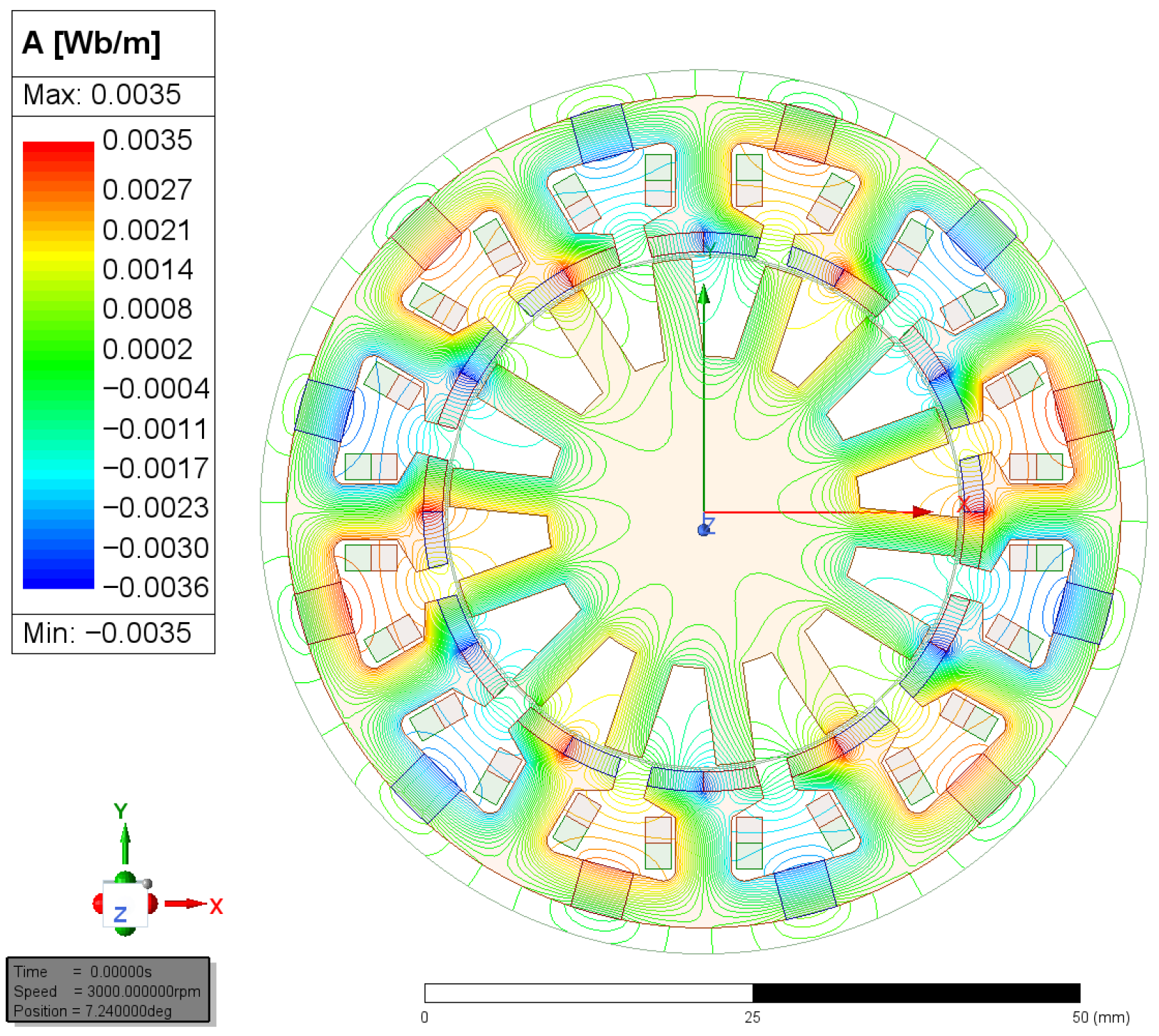
Figure 2 shows the visualization of the magnetic flux line conduction path of the motor. The color and linear distribution exhibit a good symmetrical shape, and the modularized stator presents balanced magnetic coupling characteristics, which can effectively reduce the torque ripple. The red and orange regions are mainly concentrated in the stator teeth, indicating that the main electromagnetic torque generation area of the motor is located on the stator teeth. The blue and green regions are mainly distributed in the stator yoke, showing a gentle magnetic potential gradient, which proves that the magnetic circuit design of the yoke is reasonable and that the saturation risk is low. The magnetic flux lines in the permanent magnet region are mainly blue and cyan, indicating that the permanent magnets provide reverse magnetomotive force due to the reverse distribution of magnetic potential, which cooperates with the armature. The magnetic flux lines start from the stator tooth tips, cross the air gap into the rotor, and return from the adjacent stator teeth to form a closed magnetic circuit. The flux lines have a clear direction without obvious crossing, which intuitively and strongly verifies the effectiveness of the structural improvement of the motor.
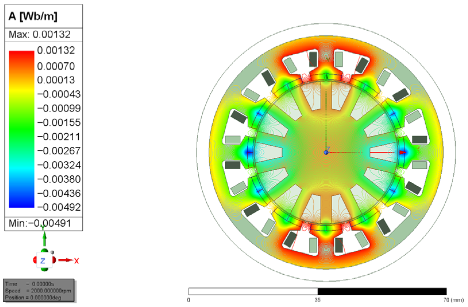
By comparison between
Figure 2 and
Figure 3, it can be seen that the magnetic field distribution in
Figure 2 is more uniform, showing better symmetry of the magnetic circuit. The variation in the magnetic potential gradient in the air gap and stator core regions is smoother, and the magnetic flux lines close along the main magnetic path, resulting in less flux leakage in the tooth-slot gaps and higher energy transfer efficiency. In contrast,
Figure 3 presents obvious local distortion of magnetic flux lines, accompanied by larger flux leakage and a lower proportion of effective magnetic flux.
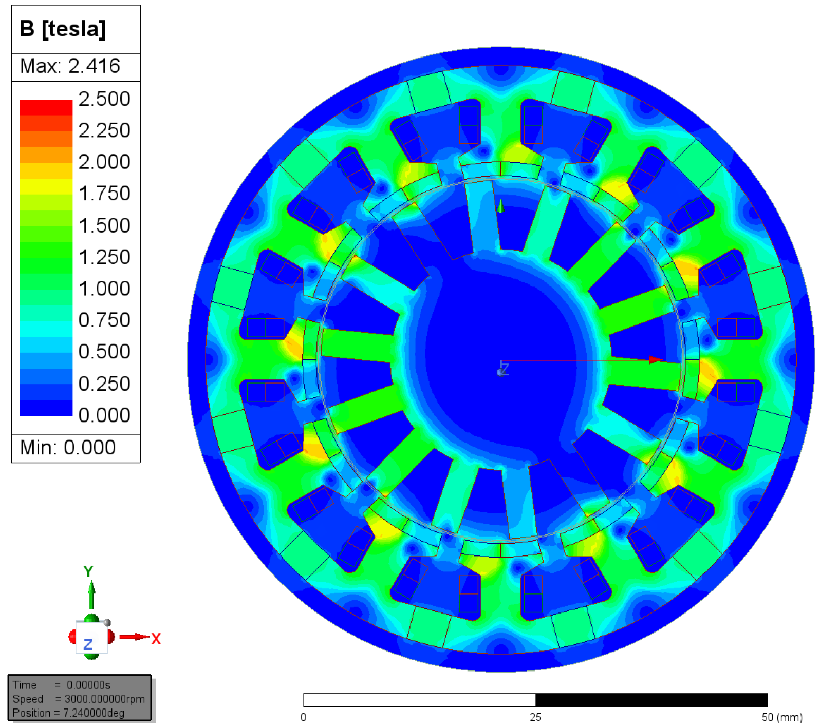
Figure 4 shows the magnetic flux density distribution of the motor. The flux density in the air-gap region is relatively uniform, and the magnetic field energy is more concentrated at the air gap, which reduces the loss caused by magnetic field dispersion. There are no obvious low-flux-density regions with magnetic flux leakage, indicating that the magnetic circuit has optimized the leakage path, greatly reduced the leakage loss, and significantly improved the magnetic field utilization. The overall magnetic field distribution is multi-stage symmetric, with a slight unbalance only in local saturated regions. Saturation exists only in a very small number of local areas, which intuitively proves that the overall design scheme is feasible.
By comparison between
Figure 4 and
Figure 5, the high-magnetic-density region in
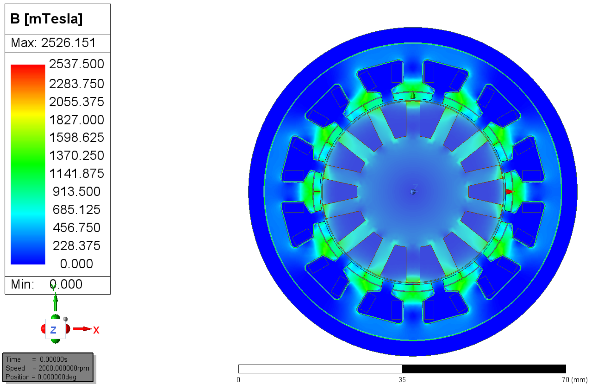
Figure 4 covers a wider range where the stator teeth, rotor, and other components are located in the strong magnetic field zone. This allows for more sufficient utilization of the core permeability, thereby delivering higher torque density. The magnetic density distribution is periodically symmetric, and the magnetic field distribution at the stator teeth is highly consistent. In contrast,
Figure 5 exhibits obvious magnetic density distortion at the stator slot openings and rotor poles, which induces severe vibration and noise in the motor and introduces additional magnetic field harmonics.
As shown in
Figure 4, the high-magnetic-density regions are mainly concentrated in the tooth parts, while the magnetic density in the yoke and rotor magnetic bridges is relatively low. This demonstrates that the thermal distribution of the proposed design is more uniform, avoiding local overheating and theoretically improving the thermal reliability under high-speed operating conditions.
Compared to
Figure 5, the magnetic flux density in
Figure 4 is significantlly higher, indicating that the magnetic circuit of the proposed design greatly reduces the magnetic reluctance and significantly improves the magnetic flux utilization ratio, allowing for more magnetic flux lines to effectively participate in energy conversion.
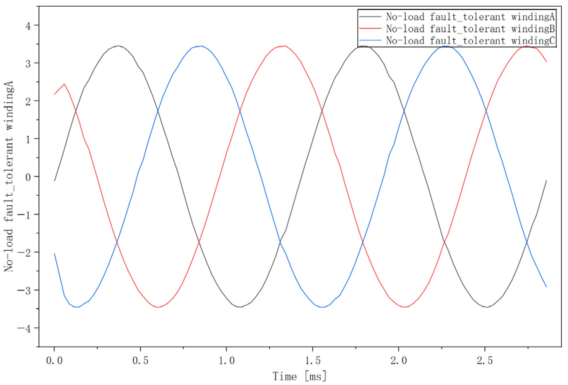
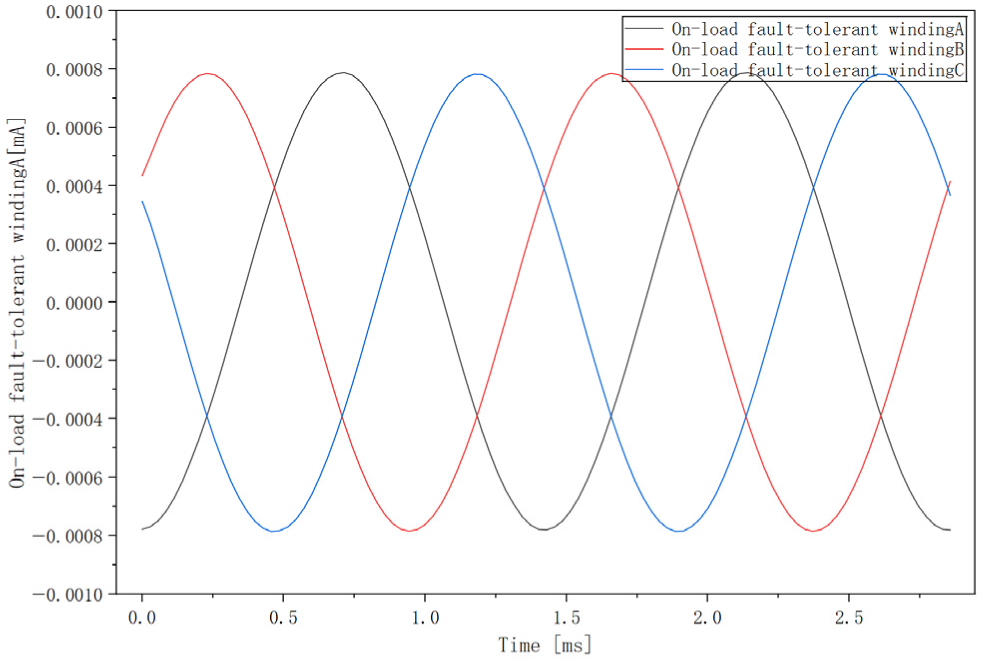
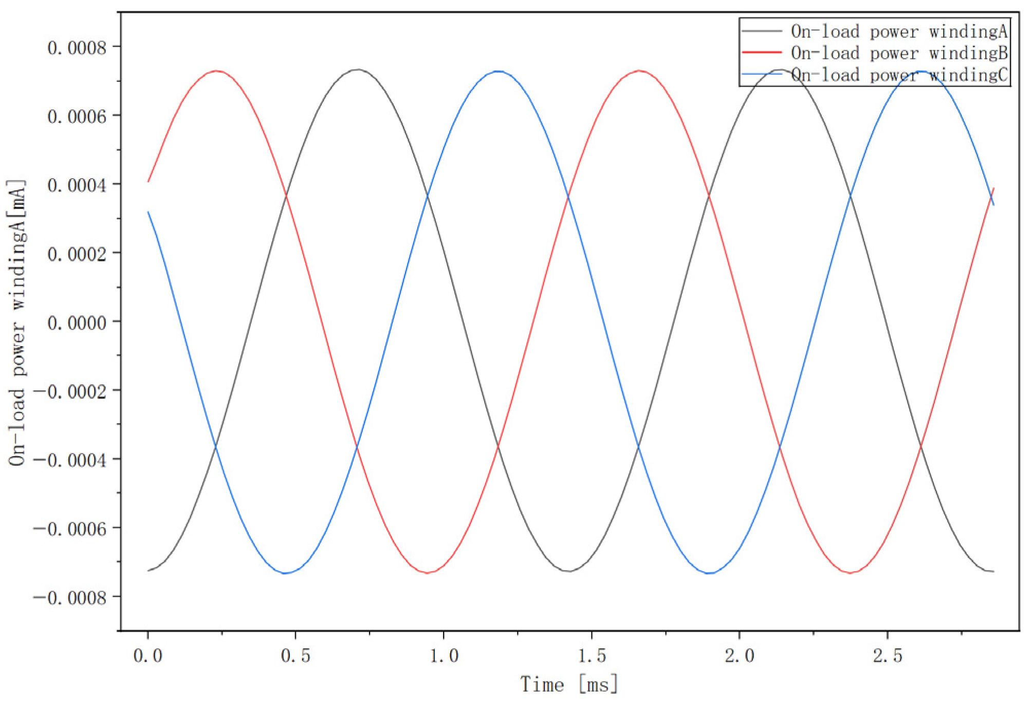
It can be seen in
Figure 6 and
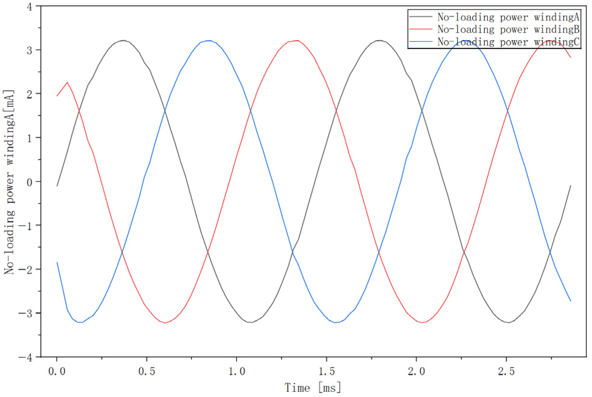
Figure 7 that the waveforms of the power winding and fault-tolerant winding present sinusoidal profiles with almost no harmonic content. The three-phase voltages, A, B, and C, are basically consistent in amplitude and phase distribution.
It can be seen in
Figure 8 and
Figure 9 that the dual-winding flux linkage waveforms have high symmetry and the positive and negative half-cycles are basically consistent, indicating that the coordinated design of the windings and permanent magnets has effectively suppressed harmonic components. Since the load flux linkage diagrams of the dual windings are independent of each other and the waveforms are synchronized, it is verified that, when a single winding fails, the other winding can quickly switch to operation, which proves the fault tolerance of the dual-winding structure.
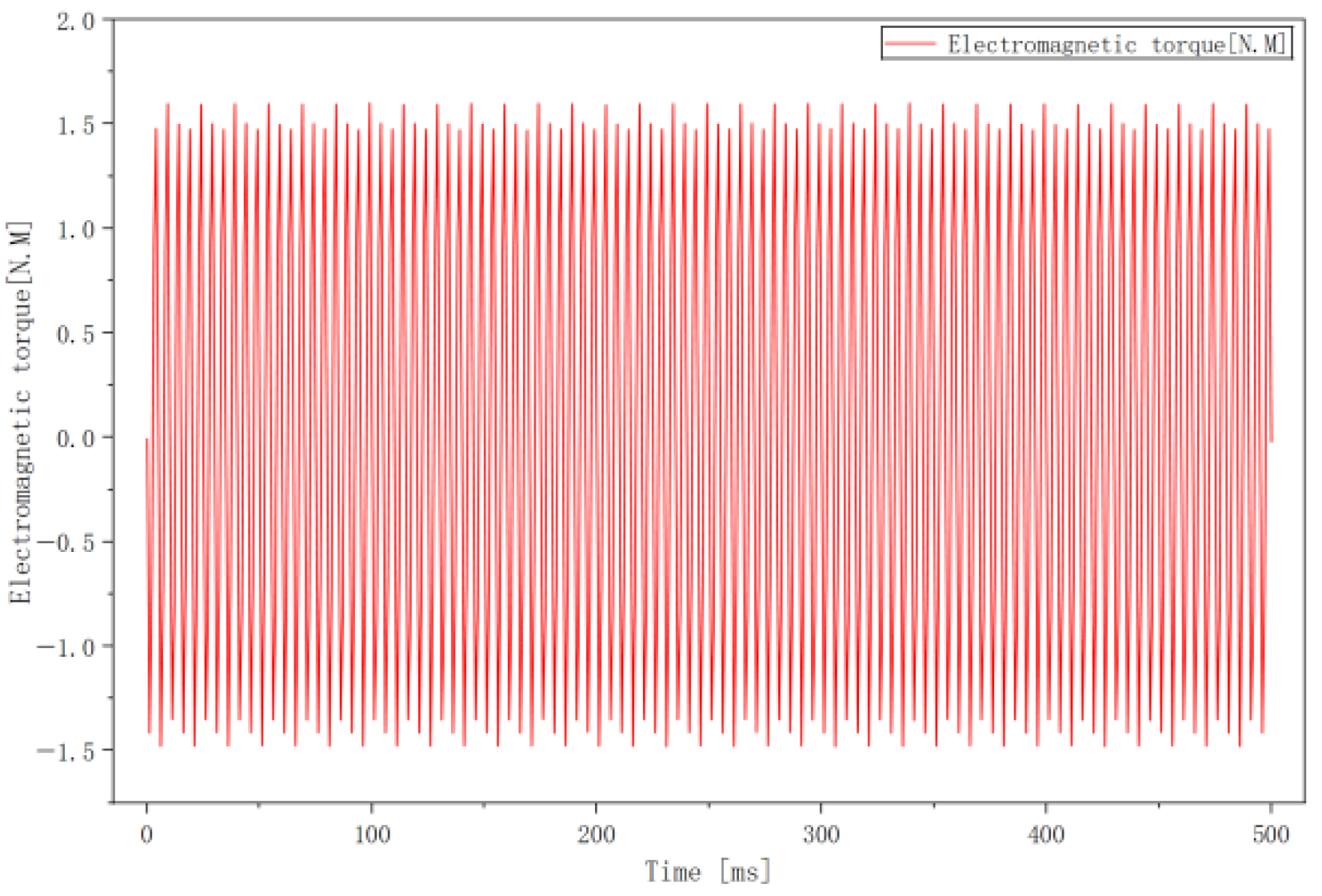
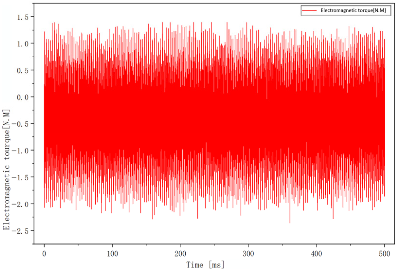
Compared to
Figure 10, the average torque in
Figure 11 increased from 0 to 0.62516 N·m, achieving a transition from no effective steady-state torque output to stable and effective torque output capability.
Figure 10 shows that the proposed motor can generate a stable positive effective torque, which demonstrates that the motor, as a power source for continuously driving loads, can output higher-intensity sustained mechanical power under the same volume. The torque density is improved, the additional losses caused by reactive oscillations are reduced, and the energy utilization efficiency of the motor is enhanced.
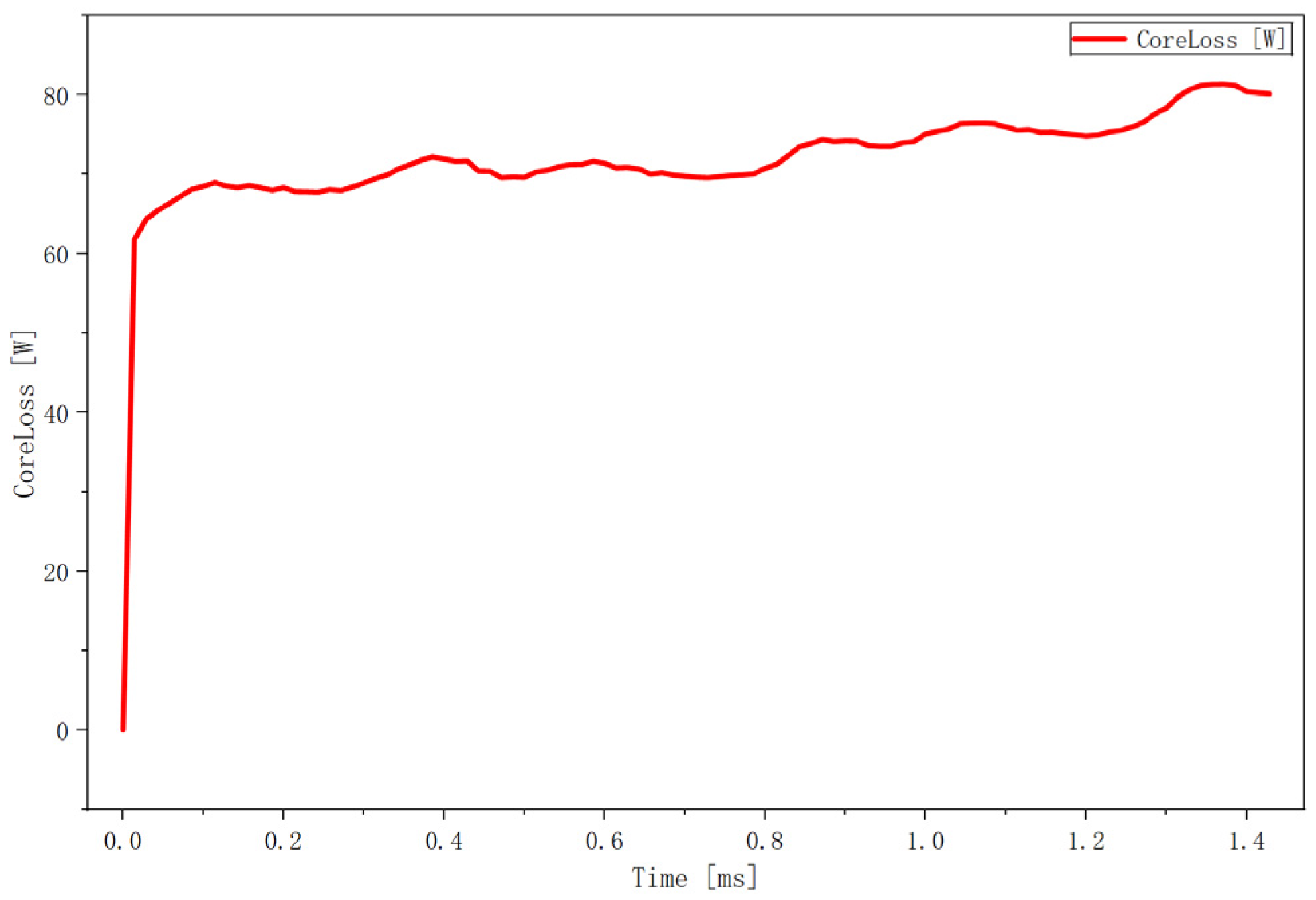
As shown in
Figure 12, the curve rises rapidly within 0–0.1 ms and increases smoothly after 0.1 ms, with no overshoot or divergence. The steady-state average power consumption is approximately 70 W, and the peak value is about 82 W.
As shown in
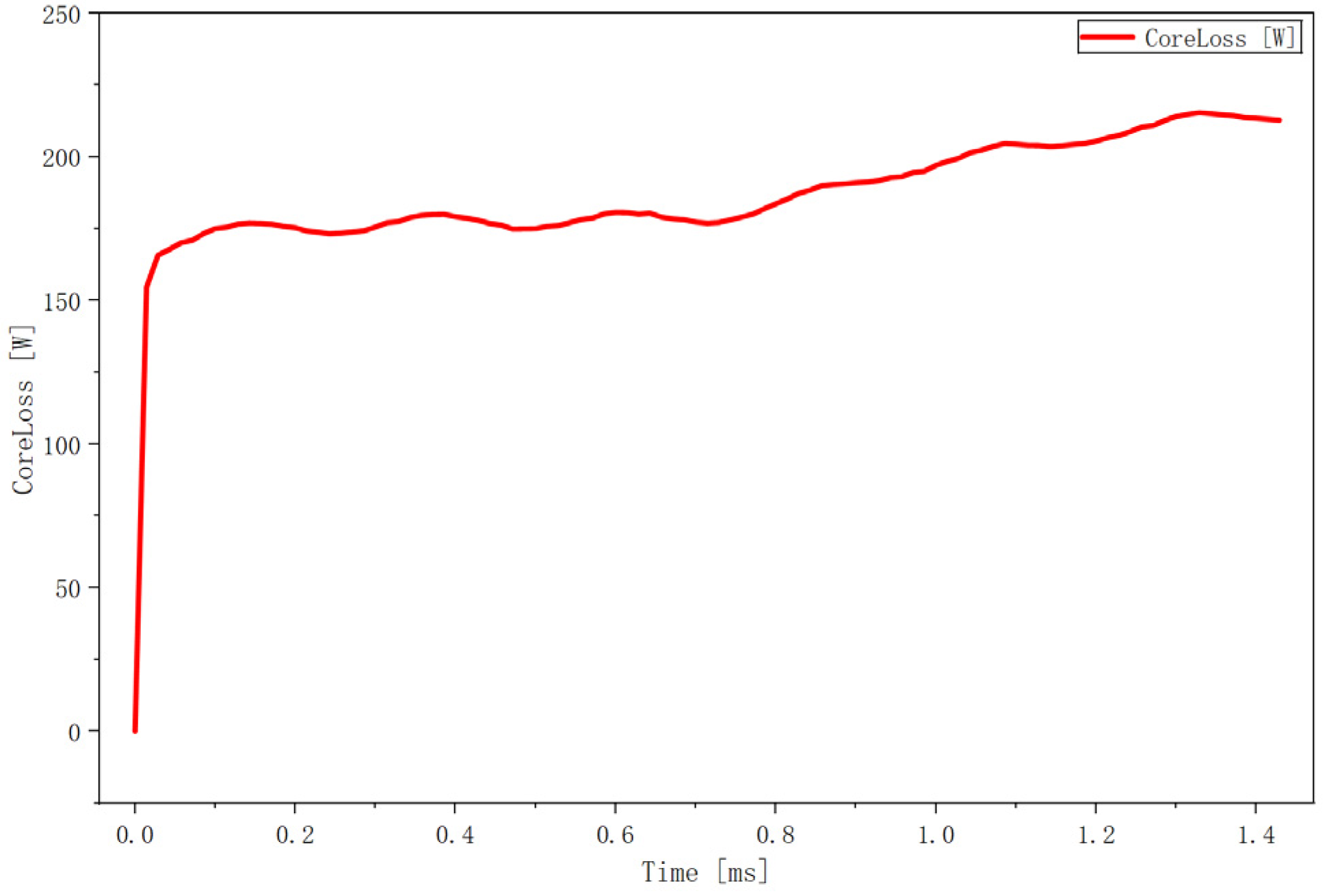
Figure 13, the steady-state power consumption is approximately 190 W, with a peak value of about 215 W.
Compared to
Figure 13, the core loss of the proposed motor is only 37% of that of the conventional flux-reversal machine, indicating a much lower loss level. This endows the motor with higher efficiency potential, making it more suitable for applications requiring frequent start–stop operations and high proportion of light-load conditions, such as robot joints. The steady-state fluctuation amplitude in
Figure 12 is about 7 W, while that in
Figure 13 is approximately 20 W, with a larger absolute fluctuation and a slow upward trend in the later operation stage. This directly demonstrates that the magnetic field alternation of the proposed motor is more balanced, the magnetic circuit saturation is lower, and the loss ripple during operation is smaller. In
Figure 12, the loss rises from 0 W to 68 W during the startup stage, whereas in
Figure 13, it increases from 0 W to 170 W. The startup loss of the latter is 2.5 times that of the former, which indicates that the proposed motor suffers a smaller magnetic shock during startup and less damage to the core structure, thus improving the startup reliability and extending the service life of the motor.
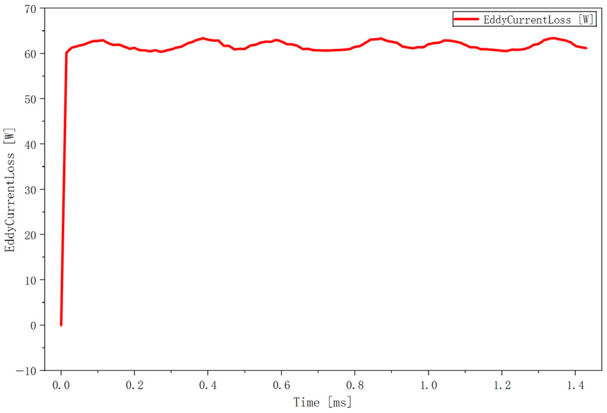
As shown in this figure, the eddy current loss in the steady-state stage is approximately 62 W, with a fluctuation amplitude of around 2 W and a relative fluctuation of only 3%, reflecting the excellent magnetic field quality of the proposed topology. The slight fluctuations in the curve are caused by the periodic variation in magnetic permeability. These fluctuations indicate that the segmented stator effectively suppresses high-order harmonics and results in a relatively uniform eddy current density distribution, verifying that the structure features low harmonics, low eddy current loss, and high operational stability.
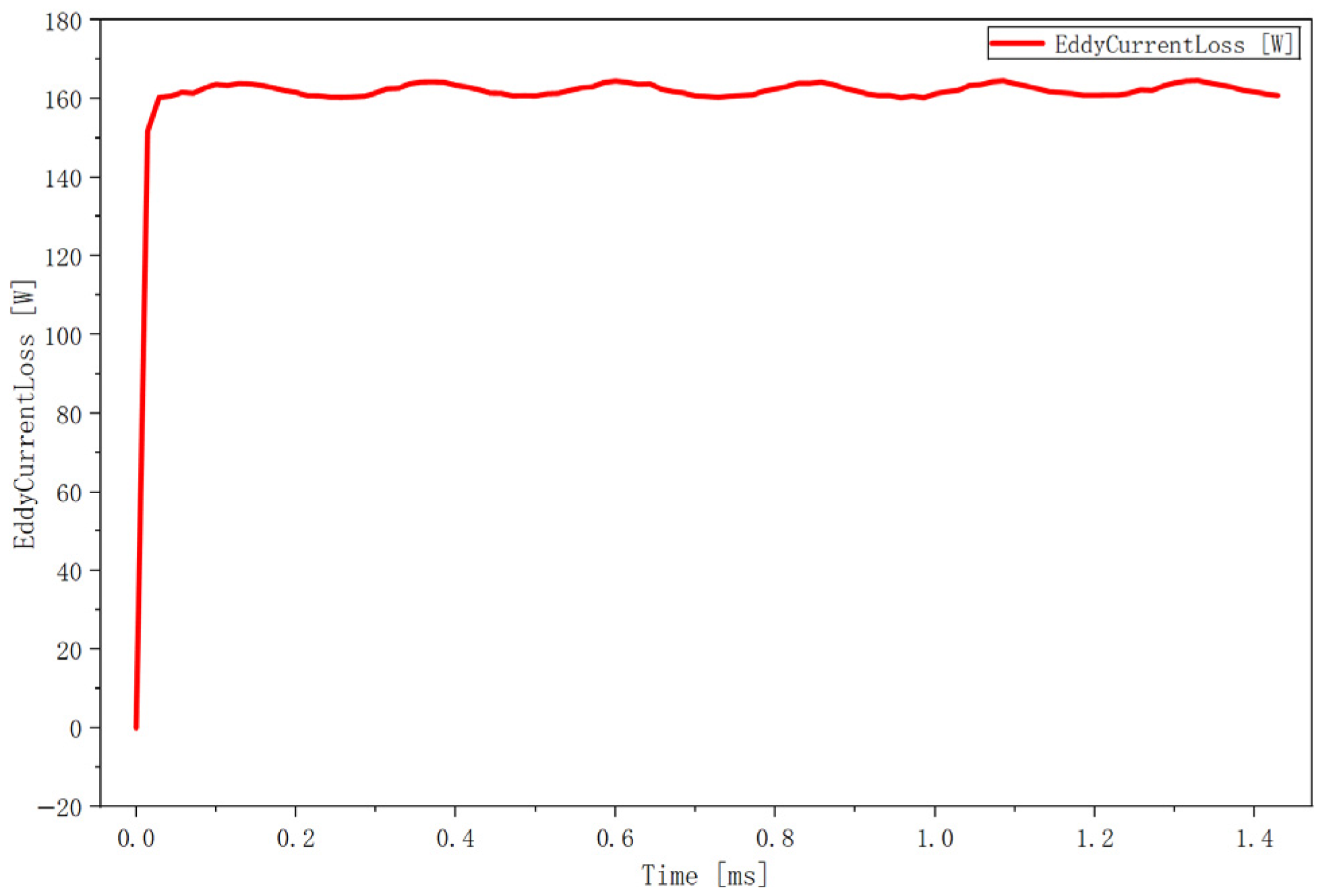
As shown in this figure, the eddy current loss in the steady-state stage is approximately 163 W, with a fluctuation amplitude of around 4 W.
Compared to
Figure 14, the proposed motor in
Figure 15 exhibits a smaller absolute fluctuation, lower loss value, and a smoother curve. During the motor startup stage, the proposed motor structure achieves a milder transient process, indicating smaller magnetic shock at startup. This effectively improves the reliability and anti-interference capability of the motor during starting.
3. Practical Feasibility and Limitation Analysis of the Proposed Design
Based on the conventional flux-reversal motor, the proposed design adopts a segmented modular stator, a dual-sequence permanent magnet topology, and an independent dual-winding configuration. In terms of electromagnetic design, dual-sequence permanent magnets can increase the air-gap magnetic flux density while suppressing magnetic saturation. The segmented stator enables magnetic circuit decoupling and reduces torque ripple. The dual independent windings separate the power windings from the fault-tolerant windings, which theoretically improves the operational stability of the motor. It can be seen that the proposed motor topology is reasonable and feasible for electromagnetic principles, which has been effectively verified through simulations.
In terms of mechanical structure, each module of the segmented stator features symmetric structure and uniform dimensions, allowing for individual stamping, winding, and insulation processing of stator segments, which facilitates assembly. The dual-sequence permanent magnets are separately mounted on the stator teeth and between stator segments, using either surface-mounted or embedded installation. Complex injection molding and overall magnetization are not required, which helps us to ensure high assembly accuracy.
In terms of fault tolerance, when a short circuit, open circuit, or other fault occurs in a single stator segment or a single winding, the remaining healthy modules can still operate normally and the motor can theoretically maintain stable operation. This fault-tolerant mechanism has been extensively validated in modular permanent magnet motors, multiphase motors, and high-reliability servo systems, confirming the feasibility of the proposed design.
Nevertheless, the proposed design still has certain limitations. The segmented stator structure imposes very strict requirements on the dimensional tolerances of stator segments. Minor deviations can lead to asymmetric magnetic circuits, uneven air gaps, and amplified torque ripple and vibration. The surface mounting and magnetization process of dual-sequence permanent magnets is complicated, which demands high precision in both polarity and position. Otherwise, problems such as magnetic field cancelation and flux leakage will occur. In addition, the segmented stator structure weakens the overall mechanical strength of the stator, so additional fastening structures are required to prevent deformation of the stator segments.