1. Introduction
To achieve global carbon neutrality, reducing emissions in the transport sector is a critical imperative. In Japan, emissions reached approximately 1 billion tons in fiscal year 2023, with automobiles accounting for more than 16% of this total [
1]. Consequently, transitioning to electric vehicles (EVs) is essential, alongside decarbonizing the power generation mix. The traction motor is the core component of the EV drive system, and its environmental impact throughout its life cycle—from material extraction to disposal—must be strictly evaluated. Currently, most EV motors are Permanent Magnet Synchronous Motors (PMSMs) that rely heavily on copper for windings and NdFeB magnets for rotors. However, copper faces risks of resource depletion and rising production-related emissions due to declining ore grades [
2,
3]. Similarly, NdFeB magnets suffer from supply instability and significant energy consumption during extraction. It is widely recognized that NdFeB magnets, with their high energy density, provide superior performance in terms of efficiency and power density compared to other machine types. Technically, it is challenging for rare-earth-free motors, such as Induction Motors (IM) or Synchronous Reluctance Motors (Syn.RM), to match the peak performance of NdFeB-based PMSMs. However, the development of future EV traction motors must not be evaluated solely by machine characteristics.
Beyond efficiency and power density, it is crucial to consider the broader environmental impact, including greenhouse gas emissions, resource depletion risks, and regional supply chain dependencies. While several studies have conducted Life Cycle Assessments (LCA) for electric motors [
4,
5,
6,
7,
8], existing research often focuses on single-dimensional evaluations, such as comparing different motor types or replacing a single material without structural optimization [
9,
10]. There is a significant research gap in understanding the complex trade-offs when multiple design variables—such as winding materials, magnet configurations (including rare-earth-free options), and specialized motor structures—are integrated and evaluated under identical output conditions.
This paper addresses these limitations by performing a comprehensive LCA of six motor configurations designed under the same outer diameter and ampere-turn constraints as a benchmark motor. The study uniquely integrates the use of aluminum windings with a dual-rotor structure to compensate for electrical conductivity trade-offs, alongside rare-earth-free designs. By evaluating emissions across both manufacturing and use stages, this research identifies the most effective motor architecture for minimizing environmental impact, providing a multi-variable perspective that shifts from a performance-centric to a sustainability-centric design philosophy.
2. The Basis of Methodology
2.1. Design Logic and Environmental Assessment Methodology
To identify the EV traction motor configuration with the lowest environmental impact, this study adopts a unified design logic that ensures technical comparability across diverse motor types. The core objective is to evaluate the trade-offs between material selection (windings and magnets) and structural modifications within a standardized performance envelope.
2.2. Unified Design Constraints
All candidate motors are designed to meet the same performance specifications as the benchmark copper-wound PMSM, which is currently used in mass-produced xEVs. To ensure a fair and practical comparison, the following parameters are strictly maintained across all designs:
Physical Envelope: The outer diameter and stack length are constrained to fit within the same vehicle packaging space, with minor adjustments to stack length only when necessary to meet torque requirements for rare-earth-free designs.
Electromagnetic Loading: The ampere-turn conditions are kept identical to ensure that the thermal and electrical stress levels remain consistent across all motor configurations.
Performance Targets: Each motor is optimized to achieve the same maximum torque and output power, ensuring that the driving performance of the vehicle remains unchanged regardless of the motor type.
2.3. Variable Parameters for Comparative Study
Under these unified constraints, we systematically vary the following design parameters to observe their direct impact on the Life Cycle Assessment (LCA):
Winding Material: Replacing copper with aluminum to evaluate the benefit of lower manufacturing emissions versus the drawback of increased resistivity.
Rotor Structure: Transitioning from a single-rotor to a dual-rotor structure in aluminum-wound designs to compensate for reduced slot area efficiency.
Magnet Configuration: Comparing high-energy NdFeB magnets with ferrite magnets or magnet-free designs (Syn.RM, IM) to analyze the trade-off between use-stage efficiency and manufacturing-stage carbon footprint.
Based on these unified design principles, we calculate and compare the emissions in both the manufacturing and usage stages. This approach allows us to clearly correlate design parameter differences—such as the increased iron loss resulting from structural changes or the reduced mass from material substitution—directly with the overall environmental assessment results.
2.4. Methods for Estimating the Environmental Impact of Motors
We aim to identify the motor for EVs with the lowest environmental impact and evaluate the following five types of motors:
Permanent Magnet Synchronous Machine (PMSM) with Copper Winding.
PMSM with Aluminum Winding.
Synchronous Reluctance Machine (Syn. RM) with Copper Winding.
Permanent Magnet assisted Synchronous Reluctance Motor (PMaSyn.RM) with Copper Winding.
Induction Machine (IM) with Copper Winding and Aluminum Bar.
For these motors, a PMSM with copper winding for xEVs is used as the benchmark, and each motor is designed to achieve the same maximum torque under the same outer diameter and ampere-turn conditions as the benchmark. Based on a survey by Japanese society IEEJ-IAS [
11], we calculate and compare the CO
2 emissions in both the manufacturing and usage stages of the designed motors to determine which motor has the lowest environmental impact. First, by comparing the two PMSMs above, we evaluate the environmental impact of replacing copper with aluminum as the winding material. In addition, as noted earlier, NdFeB magnets cause a significant environmental impact during production; therefore, attention is also paid to motors that do not use rare-earth elements in the rotor. In this study, we evaluate the environmental impact of rare-earth-free motors by comparing PMSMs with the other three types of motors.
2.5. Conceptual Electromagnetic Basis for Motor Design
The performance differences among the motors evaluated in this study can be explained by several fundamental electromagnetic principles. Although the present work focuses on comparative LCA rather than analytical derivation, the key physical mechanisms relevant to the design choices are summarized below.
Aluminum has higher electrical resistivity than copper, which increases winding losses when the same slot geometry is used. Increasing the conductor cross-sectional area reduces this penalty but also decreases the number of turns, influencing torque production. This trade-off motivates structural measures such as enlarging slot area or adopting a dual-rotor configuration.
PMSMs generate the magnet torque primarily through the interaction between stator currents and permanent-magnet flux, enabling high torque density. In contrast, Syn.RM and PMaSyn.RM rely more on reluctance torque created by rotor saliency. Because reluctance torque does not benefit from high-energy magnets, these motors typically require geometric optimization or increased stack length to meet torque targets.
It is well known that the IPMSM torque characteristic is described as (1).
where Ψ is a magnet flux linkage by the permanent magnet which generates the magnet torque, and (L
d − L
q) is the inductance difference; saliency by the magnetic resistance difference between d and q axis generates the reluctance torque.
SPMSMs provide strong magnetic torque but expose magnets to time-varying fields, increasing magnet losses. IPMSMs embed magnets within the rotor, allowing the motor to utilize both magnetic and reluctance torque while reducing magnet loss and magnet volume. The SPMSM can use only magnet torque; the first term of (1), and the IPMSM can use both the magnet torque and the reluctance torque.
Changes in rotor geometry, magnet placement, and slot area alter the magnetic flux path in the core. These changes affect hysteresis and eddy-current losses. For example, PMaSyn.RM redistribute flux to enhance reluctance torque. These qualitative principles explain the efficiency differences observed in the simulation results. The loss is calculated by using Steinmetz equation as shown in (2).
where the first term is hysteresis loss and the second term is eddy-current loss,
B is flux density and
ω is angular velocity of the flux. In this study, the iron loss of each motor is calculated by using the flux density of Finite Element Analysis results and (2).
Kh and
Ke are obtained from a database in the material.
3. Motor Design
3.1. PMSM with Copper Winding
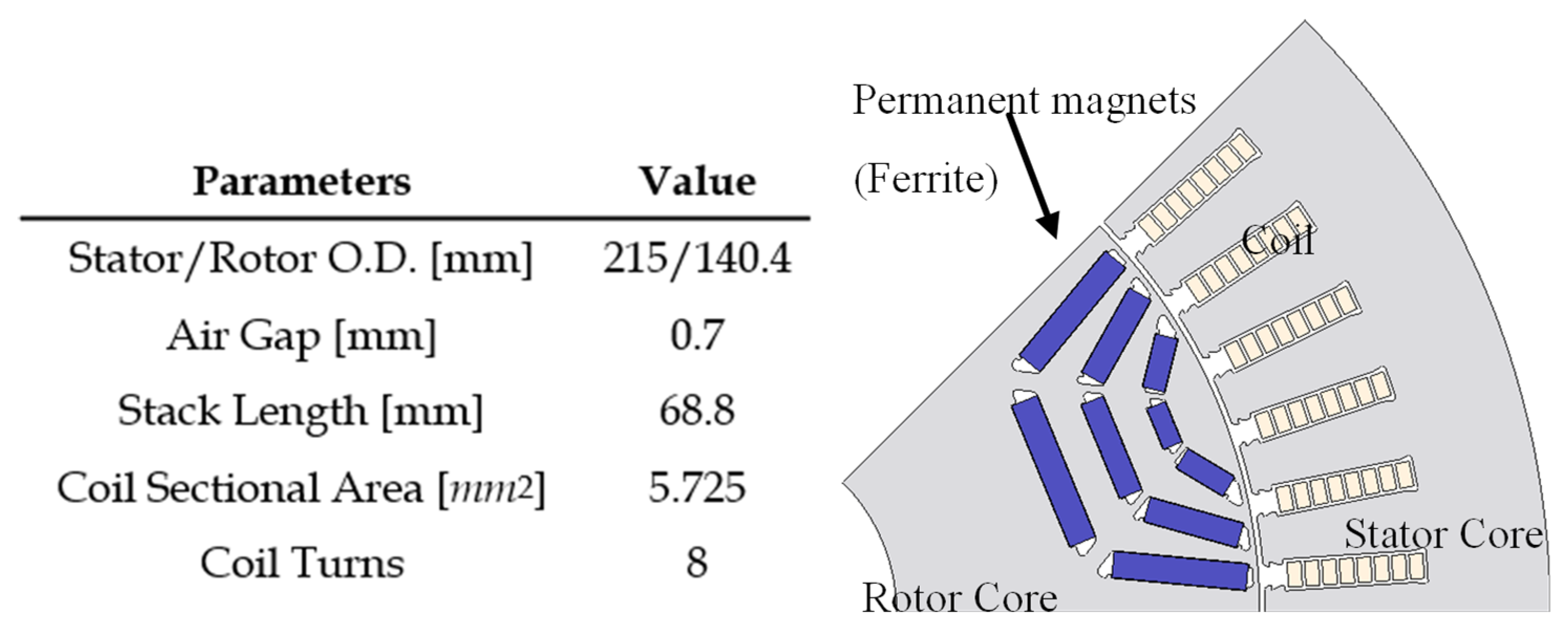
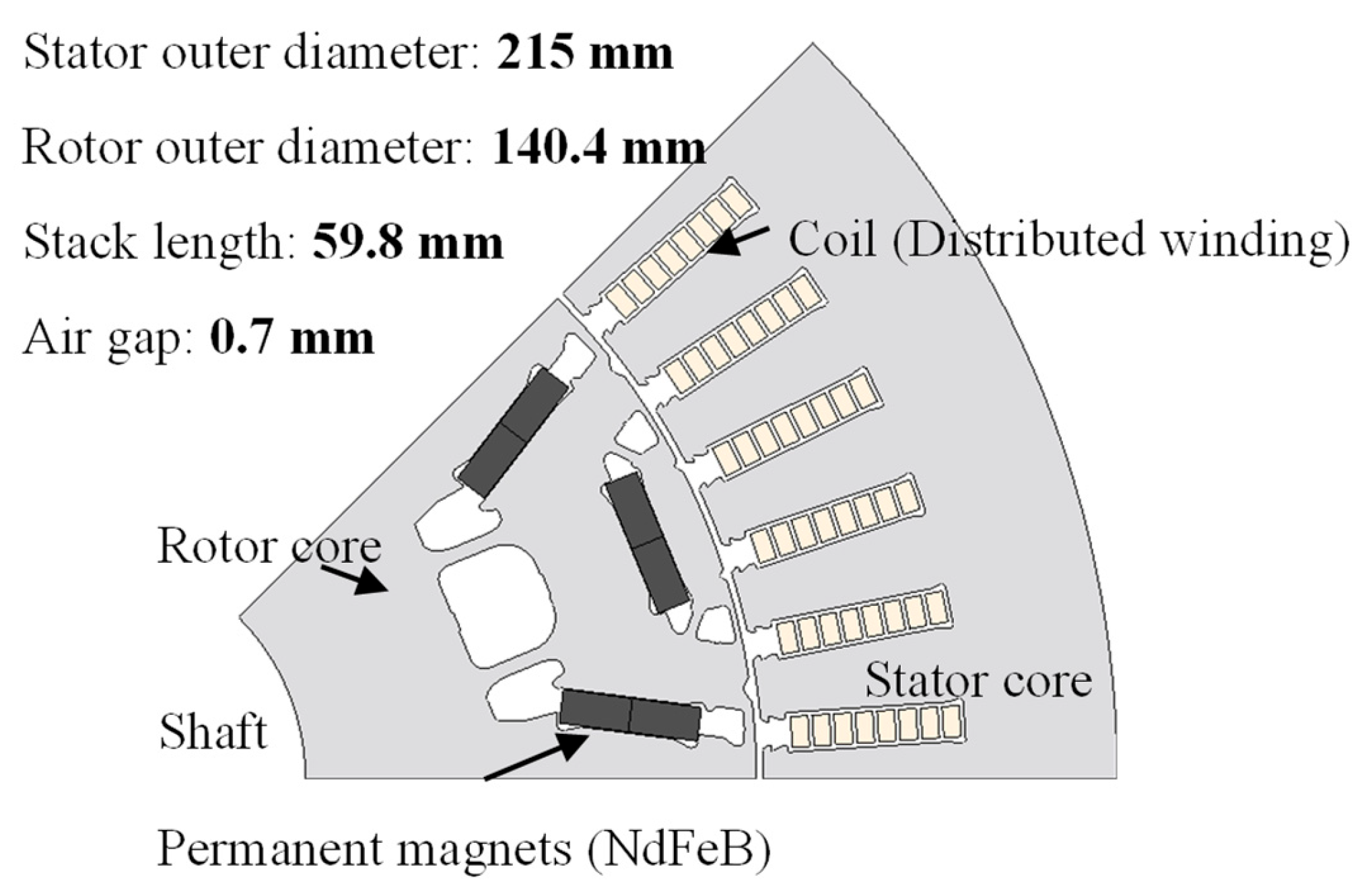
The existing EV motor is selected as a benchmark, and an analysis is conducted on this motor. The model of the benchmark motor is shown in
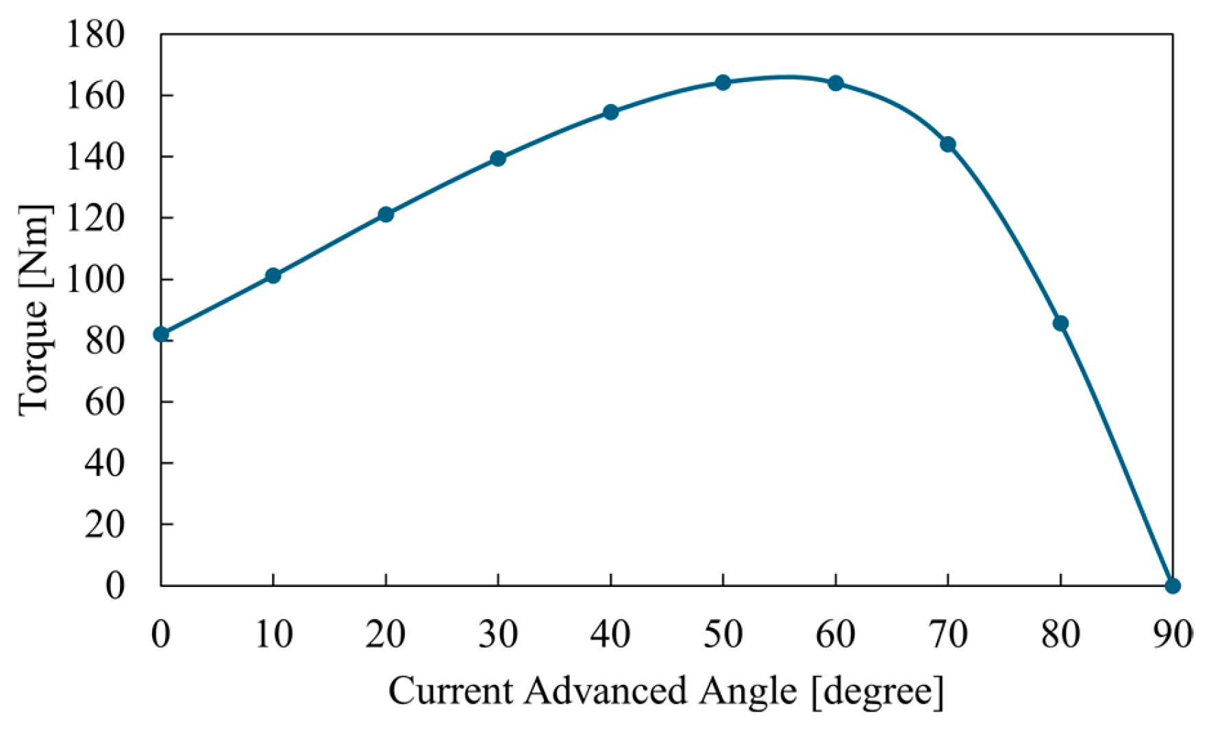
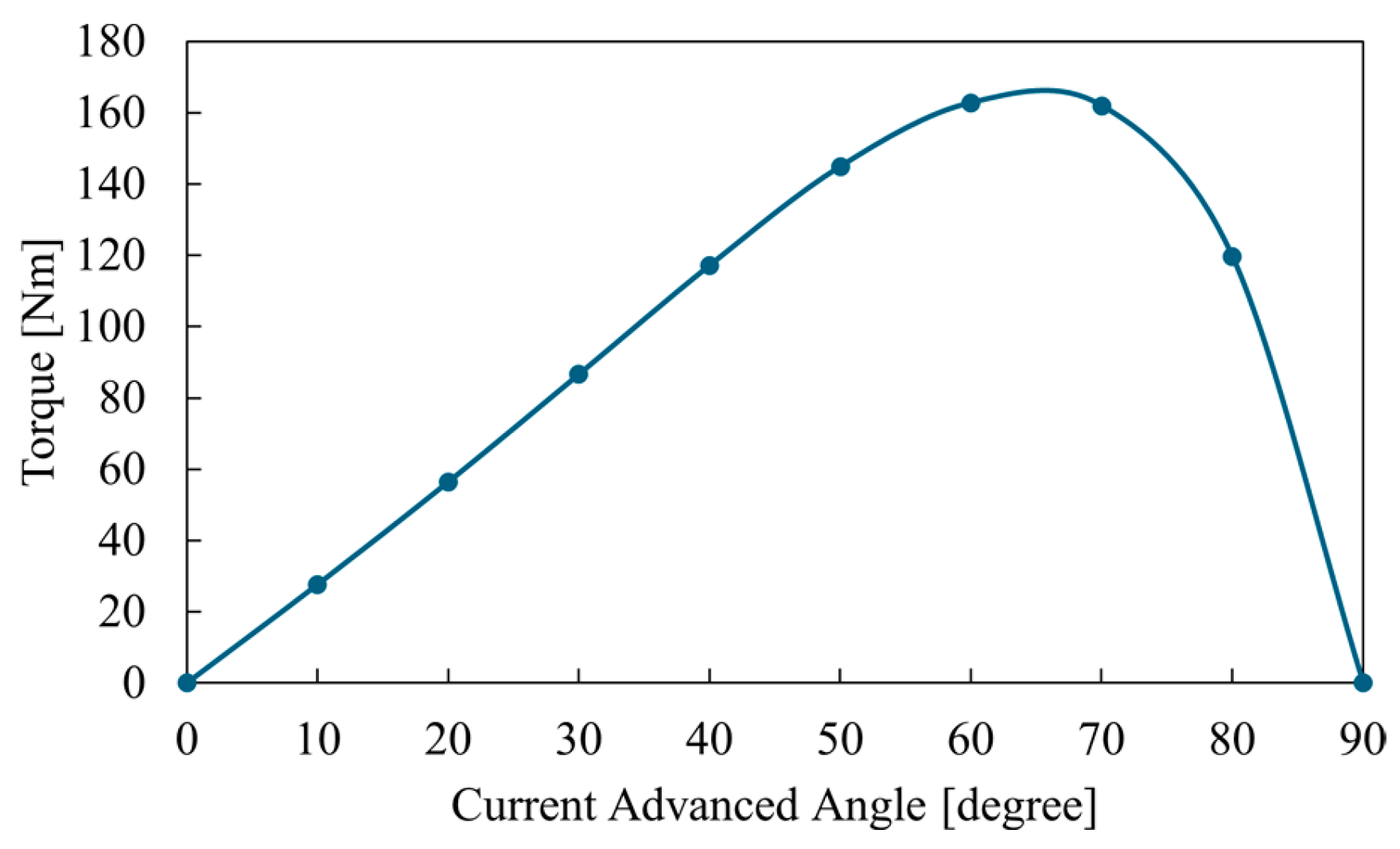
Figure 1, its dimensions are shown in the figure. The Nd-Fe-B permanent magnet NMX-S49CH is used for the IPMSM, 0.35 mm electric steel sheet 35H230 is used for both rotor and stator core. To evaluate its characteristics the electromagnetic field analysis is performed using JMAG@JSOL Corporation, and the obtained torque versus current advance angle characteristics are shown in
Figure 2.
From
Figure 2, the motor produces a maximum torque of 163 Nm, and its maximum output power is 53 kW. The feature of the IPMSM is to be able to output both the magnetic torque and the reluctance torque as (1), then, the torque density is high.
The motors designed in the following sections aim to achieve a maximum torque of approximately 163 Nm and a maximum output power exceeding 53 kW, under the same outer diameter and ampere-turn conditions as the benchmark motor. In addition, all motors are designed to achieve a safety factor of 1.5 at a maximum rotational speed of 17,000 rpm.
3.2. PMSM with Aluminum Winding
3.2.1. Dual Rotor PMSM with Aluminum Windings
Because the resistivity of aluminum is approximately 1.6 times higher than that of copper, replacing copper with aluminum while maintaining the same winding geometry increases the resistance and reduces efficiency. Studies have been made to reduce winding resistance by increasing the slot fill factor through coil precompression and optimization of coil geometry [
12,
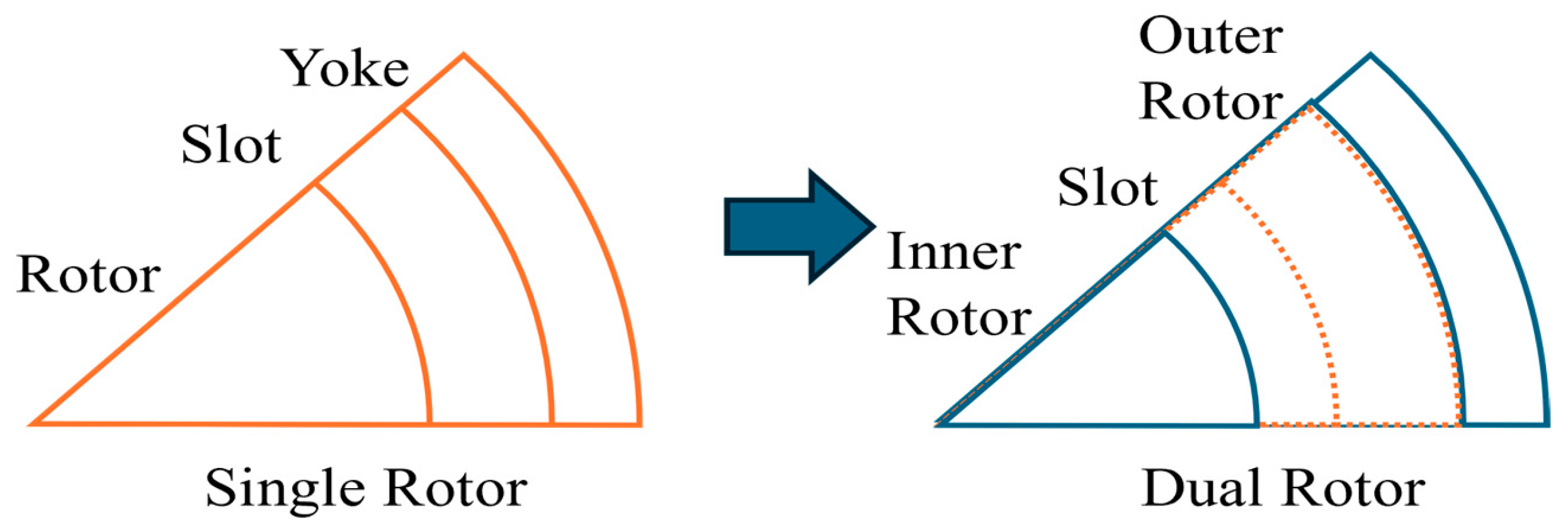
13]. However, in this study, the slot fill factor is kept constant, and the winding cross-sectional area is increased by a factor of 1.6 to reduce the winding resistance. However, increasing the cross-sectional area reduces the number of turns, which leads to a decrease in torque density. To address this issue, the motor adopts a dual-rotor structure, in which the outer diameter of the inner rotor is reduced to enlarge the slot area, and the stator back yoke is used as an outer rotor, thereby improving torque density as shown in
Figure 3. In addition, since an exposed outer rotor cannot withstand mechanical stress, a reinforcing structure consisting of an outer cylinder and a CFRP is provided around the outer rotor to ensure sufficient mechanical strength. Although many studies have been conducted on dual rotor motors with toroidal windings [
14,
15], this study used distributed winding due to its higher torque density.
3.2.2. Investigation of the Outer Rotor Structure
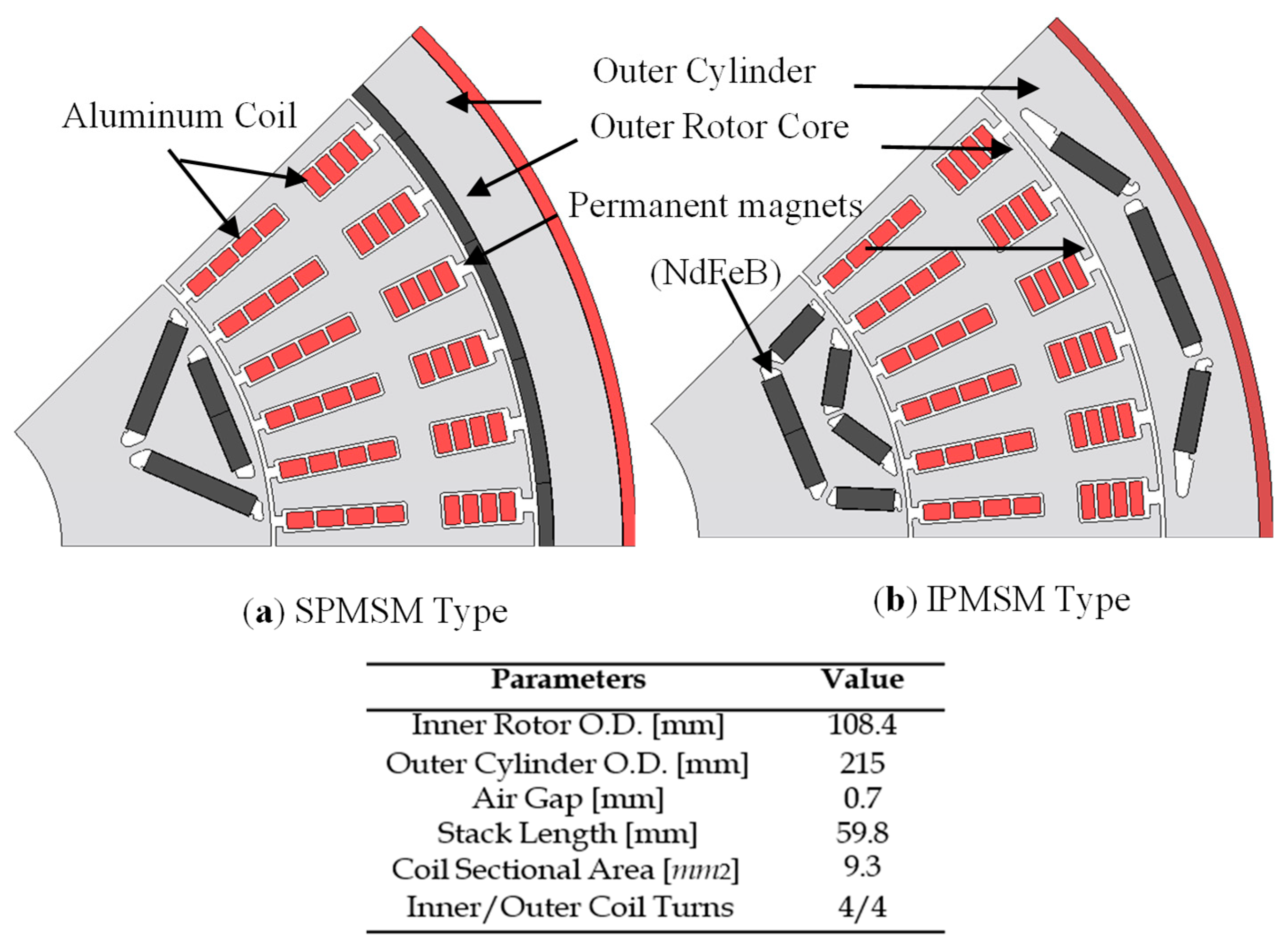
The structure of the outer rotor is examined by comparing the Surface Permanent Magnet Synchronous Motor (SPMSM) and the Interior Permanent Magnet Synchronous Motor (IPMSM) configurations. The designed motor models are shown in
Figure 4, with their specifications also in the
Figure 4. For the SPMSM, a Halbach array is adopted to improve torque density. Since the Halbach array concentrates magnetic flux on one side, flux tends to flow less through the rotor core. Therefore, to reduce motor weight, aluminum is selected as the material for the outer cylinder. However, because the magnets in an SPMSM are placed on the rotor surface, eddy-current losses in the magnets are relatively large, which is disadvantageous in terms of efficiency. To reduce magnet losses, an IPMSM is also designed. Furthermore, the IPMSM can utilize reluctance torque, allowing for a reduction in the amount of magnet material. The comparison of magnet amount is shown in
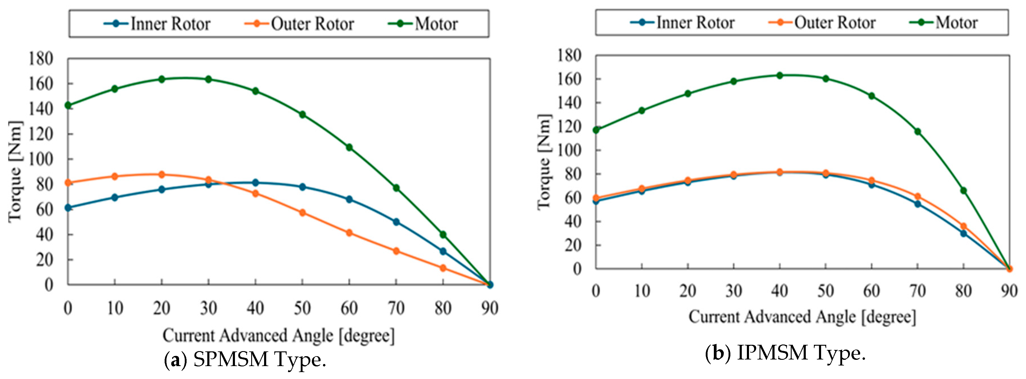
Table 1. However, unlike the Halbach array, magnetic flux in the IPMSM tends to flow into the rotor core. To alleviate magnetic saturation, S45C steel is therefore used as the material for the outer sleeve. In addition, as the transition to an IPMSM outer rotor changes the current advance angle that produces the maximum torque compared with the SPMSM, the shape of the inner rotor is modified to better utilize the reluctance torque. Although both models use distributed windings, meaning that the core between the inner and outer coils is magnetically unnecessary, a 5 mm gap is kept to secure space for stator fixation. As in the winding comparison, the outer diameter of the outer cylinder is kept the same as that of the benchmark motor. The torque characteristics with respect to the current advance angle are shown in
Figure 5. From
Figure 5, both motors achieve the target torque. A comparison of these motors from the viewpoint of environmental impact will be discussed later.
3.3. Syn.RM with Copper Winding
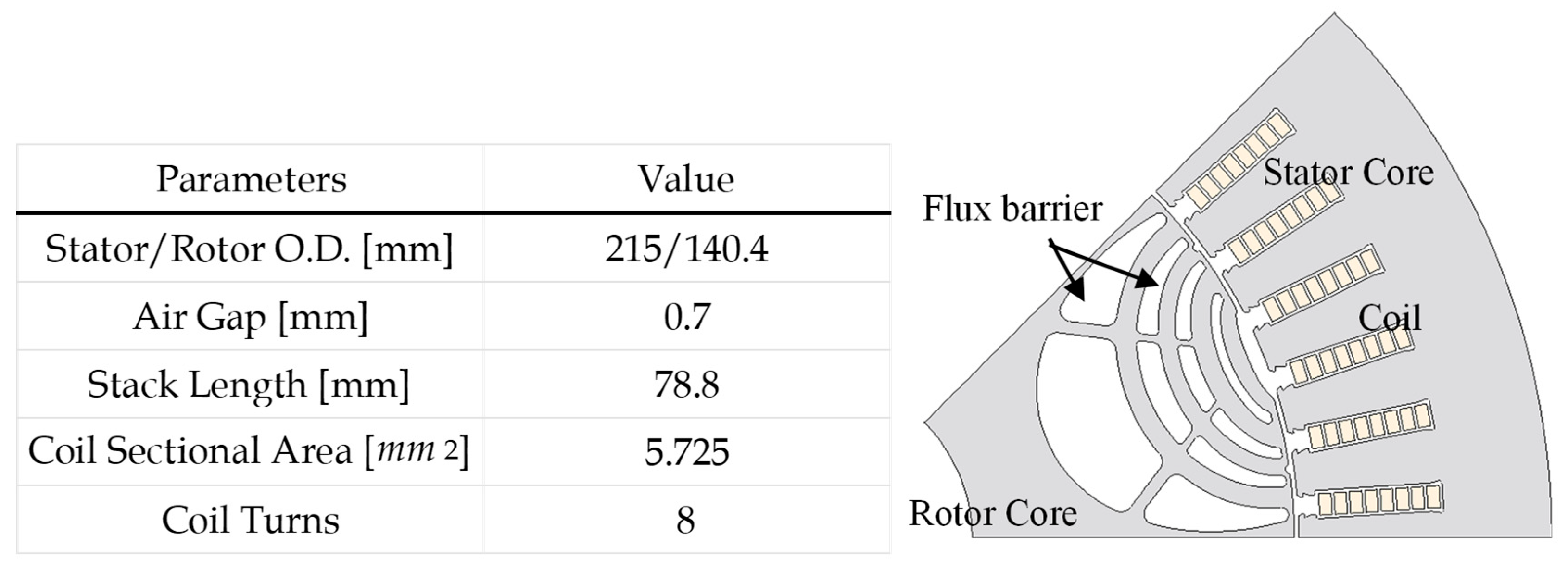
A magnet-free motor, Syn. RM, is designed. For simplicity, the stator from the benchmark motor is reused, and only the rotor shape is modified. An elliptical flux barrier centered on a reference point located on the outer periphery of the rotor is adopted. The rotor shape is optimized under the condition of maximizing the maximum synchronous torque by varying the number of flux barrier layers, the number of bridges for mechanical strength, and the geometry of each flux barrier layer. The model of the designed motor is shown in
Figure 6 and its specifications are also shown in
Figure 6.
A torque equation of Syn.RM is described as (3).
Since Syn.RM does not utilize the magnetic torque generated by permanent magnets, its torque density is lower than that of PMSM. In addition, due to its structural characteristics, Syn.RM exhibits a low power factor, resulting in a less flux-weakening effect and consequently lower high-speed output power. Therefore, the current input and stack length are increased to achieve both the target torque and output performance comparable to the PMSM. The analyzed current advance angle vs. torque characteristics are shown in
Figure 7.
3.4. PMaSyn.RM with Copper Winding
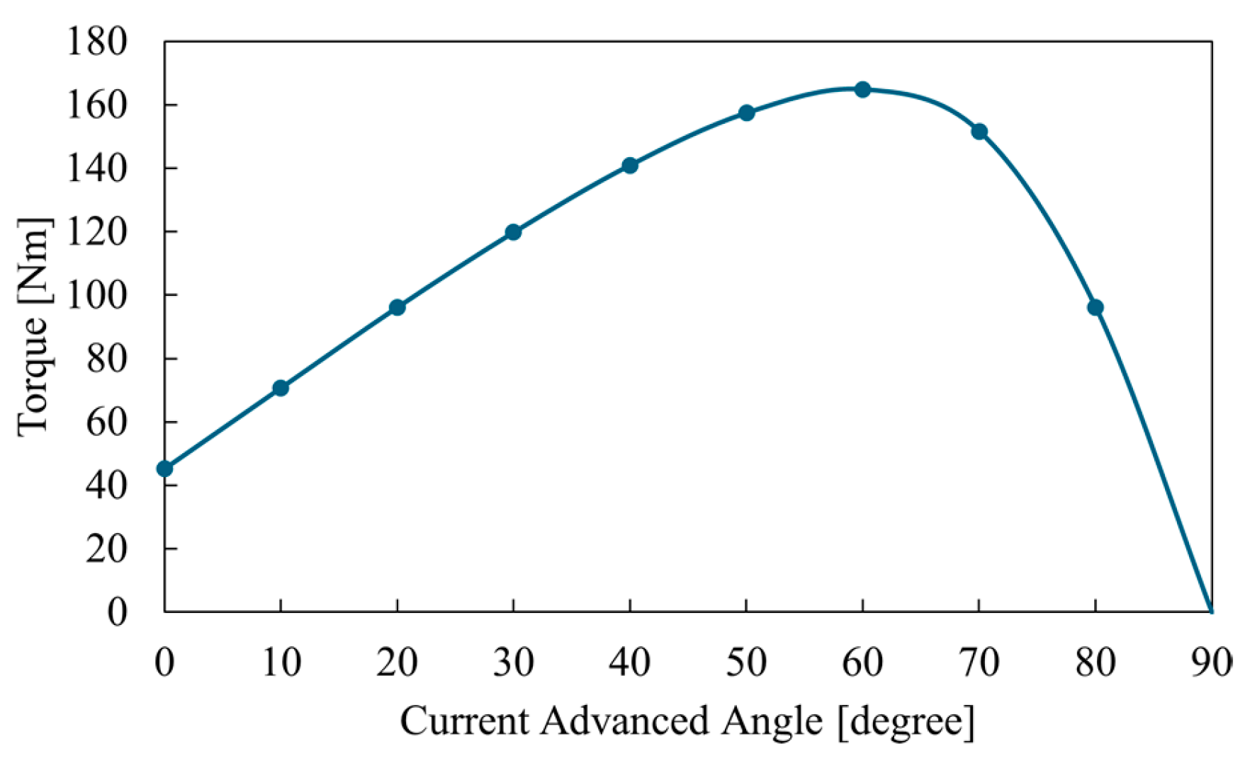
As with the Syn.RM, the stator of the PMaSyn.RM is taken from the benchmark motor for simplicity, while the rotor geometry is redesigned. Unlike the PMSM, the PMaSyn.RM uses ferrite magnets as permanent magnets. Therefore, although it is a rare-earth-free motor, ferrite magnets have a less magnetic flux density than NdFeB magnets, making it difficult to generate sufficient magnetic torque. To address this, a motor structure is proposed in which ferrite magnets are embedded in flux barriers designed to effectively utilize reluctance torque. The number of flux barriers, the shape of each layer, and the number of bridges, are optimized under the condition of maximizing the maximum synchronous torque. For ease of magnet fixation, rectangular flux barriers are adopted. The model of the designed motor is shown in
Figure 8 and its dimensions are also shown in
Figure 8. As mentioned earlier, since the torque equation of PMaSyn.RM is (1), the magnetic torque of the motor is relatively small due to ferrite magnets, its torque density is lower than that of the PMSM. Therefore, the stack length is increased to meet the target torque. The analysis resulting in current advance angle vs. torque characteristics are presented in
Figure 9. From
Figure 9, the designed motor successfully achieves the target torque due to its longer stack length.
3.5. Induction Motor with Copper Winding
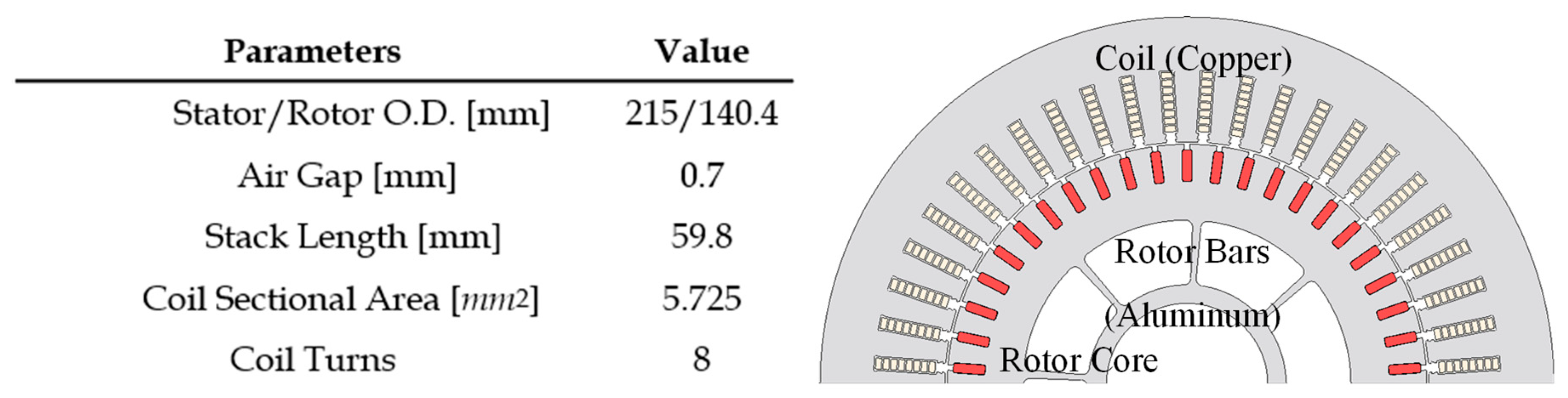
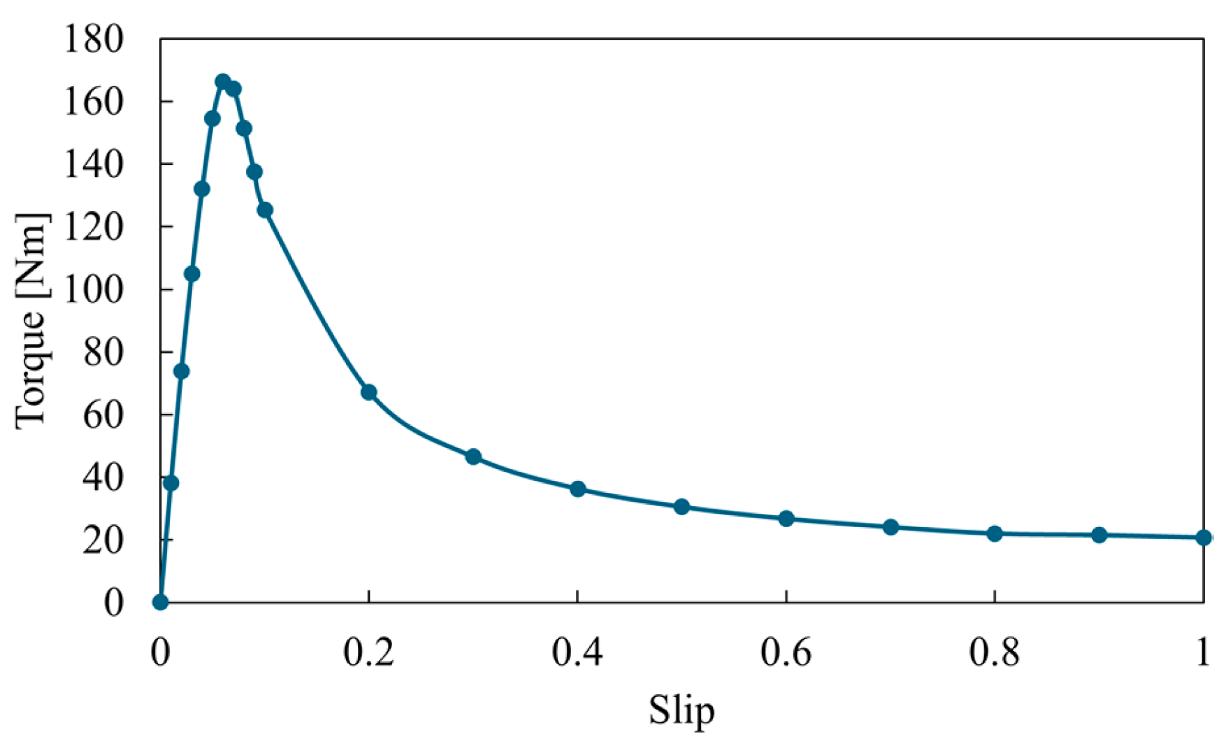
IM also uses the benchmark stator. In this study, a squirrel-cage rotor is employed to avoid efficiency reduction caused by slip rings. Furthermore, a deep-bar squirrel-cage rotor is adopted to improve torque under high-slip conditions. In addition, aluminum is used for rotor bars because it is lightweight, cost-effective, and easy to cast. The output torque of IM is in proportion to the slip; however, the larger slip makes the larger rotor joule loss. Then, by varying the shapes of the rotor cage and end ring, the model that achieves the target torque with the lowest rotor joule loss is selected. Since magnetic flux does not flow through the inner side of the rotor core in this induction motor, unnecessary material is removed to reduce motor weight. The model diagram of the designed motor is shown in
Figure 10 and its specifications are also shown in the figure. The analysis result of current advance slip vs. torque characteristics is presented in
Figure 11.
4. Environmental Impact Assessment During the Manufacturing Stage
The environmental impact during manufacturing is evaluated according to the following procedure:
The weight of each material used in the motors to be compared is determined.
The environmental impact is calculated by multiplying the weight of each material by the amount of carbon dioxide emitted per kilogram of that material during its production and then summing all the results.
4.1. Motor Weight and Material Costs
4.1.1. Calculation of Motor Weight
The motor weight is calculated by multiplying the volume of each motor material by its density. In this study, only the rotor and stator weights are considered. In addition, a coil end length of 35 mm on each side is considered. The densities of the materials used in the calculation are listed in
Table 2, and the calculated weights of each motor are shown in
Table 3. From
Table 3, it can be seen that the PMSMs with aluminum winding are lighter. In this study, the coil sectional area of the aluminum winding is enlarged to approximately 1.6 times that of the copper winding to equalize their resistances, resulting in an aluminum winding volume about 1.6 times larger. However, because the density of aluminum is less than one third of that of copper, the winding weight is ultimately reduced. This is a major advantage of using aluminum windings.
4.1.2. Calculation of Material Costs
The material cost for each motor is obtained by multiplying the material weights in
Table 3 by their respective unit prices. Note that, for the electromagnetic steel, the weight given in
Table 4—calculated separately, taking punching into account—is used instead of the value in
Table 3. This value is obtained by multiplying the density in
Table 2 by the volume calculated as the stack length multiplied by a square with a side equal to the inner diameter of the outer rotor for the PMSMs with aluminum winding, and to the stator outer diameter plus 40 mm for the other motors. The unit prices used in the calculations are listed in
Table 5, and the resulting material costs for each motor are summarized in
Table 6. Prices are based on Japanese market conditions and are calculated using an exchange rate of 1 USD = 150 JPY. From
Table 6, the material costs of copper, electrical steel, and neodymium magnets are high. Consequently, the IM, which has a smaller stack length and does not use neodymium magnets, has the lowest material cost. In addition, since aluminum is cheaper than copper, the PMSM with aluminum windings is cheaper than the benchmark motor.
4.2. Calculation of Environmental Impact During the Manufacturing Stage
In this study, the CO
2 emissions associated with producing the materials required for motor manufacturing are calculated, and the total emissions across all materials are used to evaluate the environmental impact. Emissions generated during manufacturing processes such as punching are not considered. For electromagnetic steel sheet required to produce one motor, the weight given in
Table 4 is used, whereas the weights of all other materials are taken from
Table 2. The CO
2 emission factors per kilogram of each material used in the calculations are listed in
Table 7 which values are investigated and summarized by IEEJ-IAS [
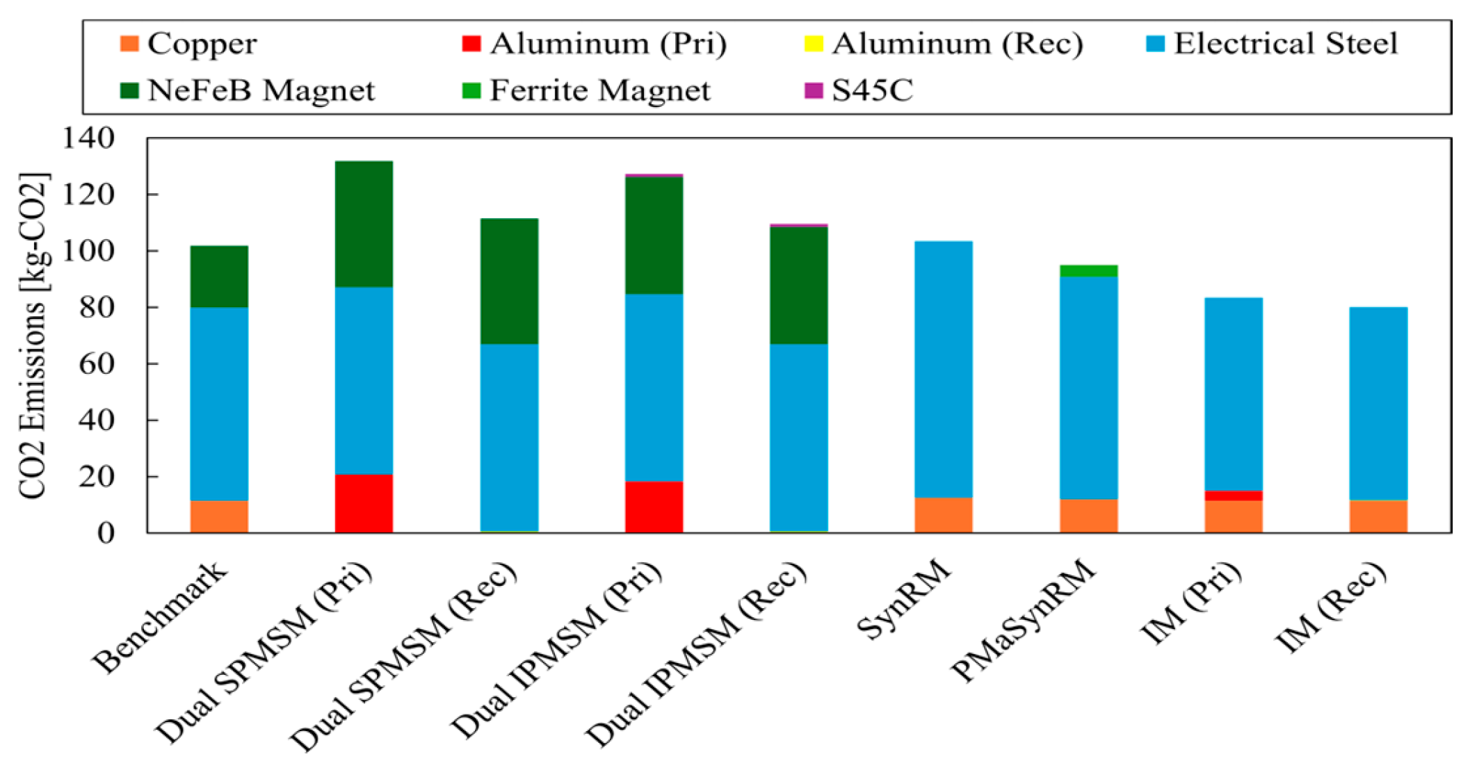
11]. In addition, because this study focuses on the relative ease of recycling aluminum due to its lower melting point compared with steel, the
CO2 emissions for aluminum are calculated using both primary and recycled aluminum. A comparison of the calculated CO
2 emissions for each motor is presented in
Figure 12.
Figure 12 shows that the impact of electromagnetic steel and NeFeB magnets is significant. Consequently, the environmental impact during the manufacturing stage is low for the rare-earth-free motors, PMaSyn.RM and IM. On the other hand, although Syn.RM is magnet-free, the increased lamination stack due to insufficient output density results in a large contribution from the electromagnetic steel, yielding an environmental impact comparable to that of the benchmark motor. For the PMSMs with recycled aluminum winding, the environmental impact of the winding is significantly reduced compared with the benchmark; however, the impact associated with the NdFeB magnets approximately doubled, leading to an overall increase in the motor’s total environmental impact.
5. Environmental Impact Assessment During the Use Stage
The environmental impact during the use stage is evaluated using the following procedure:
Efficiency maps are obtained for the motors under comparison in terms of environmental impact.
Based on the obtained efficiency maps, driving simulations are conducted for EVs equipped with each motor to calculate their energy consumption. From this, the total electricity required for 150,000 km of driving is determined, and the associated CO2 emissions from electricity generation are calculated.
Finally, the environmental impact is assessed by comparing EVs equipped with all the motors.
5.1. Acquisition and Evaluation of Efficiency Maps
5.1.1. Acquisition of Efficiency Maps
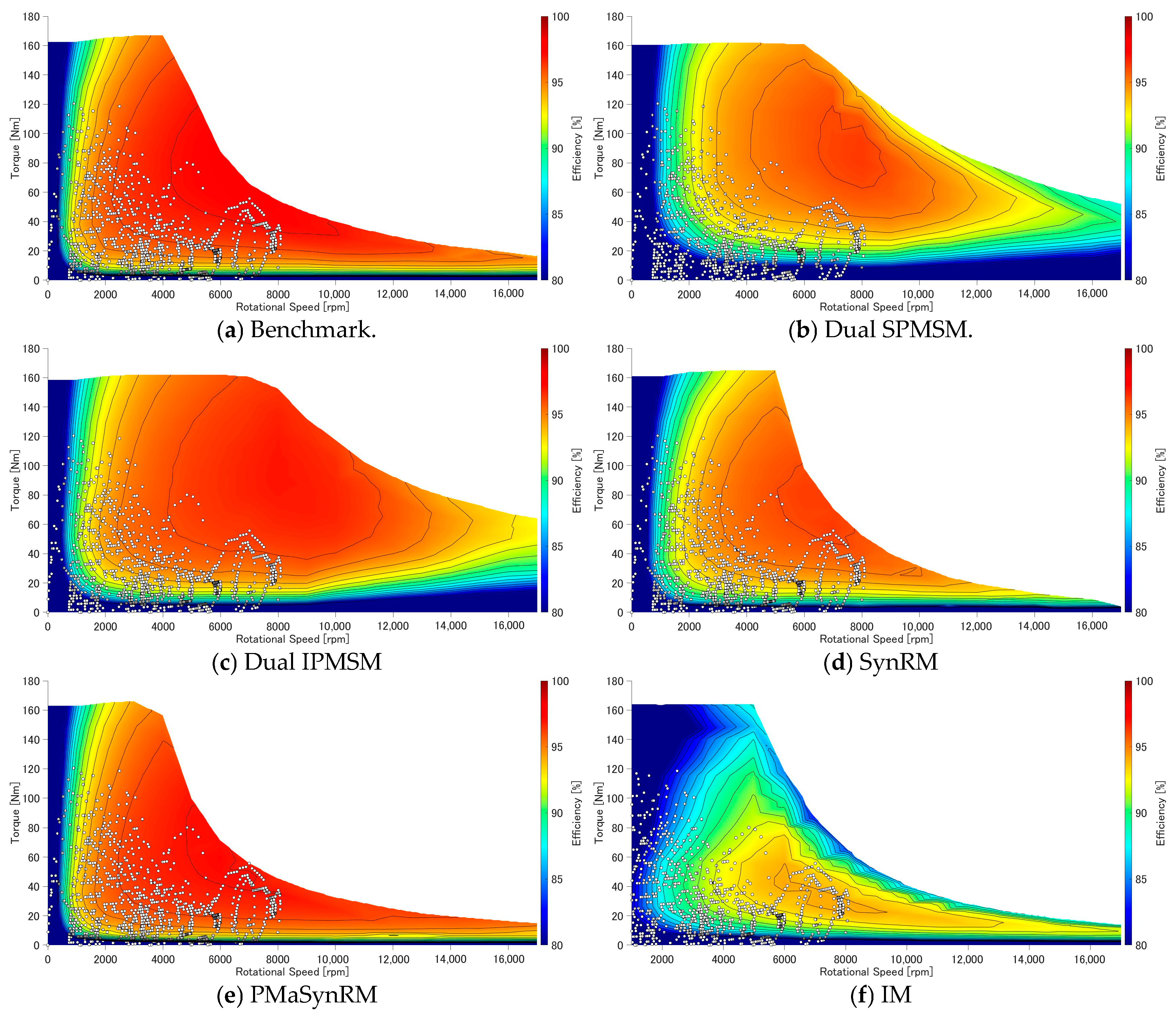
The efficiency maps are obtained using JMAG. The parameters used for generating the efficiency maps are listed in
Table 8, and the resulting efficiency maps are presented in
Figure 13. In this study, PWM excitation is employed, and the rotor and stator iron loss, DC copper loss, AC copper loss, eddy-current loss in the magnets and outer sleeve, and mechanical loss are all taken into consideration. As noted earlier, the Syn.RM is assigned higher input current and voltage than the other motors. In addition, the operating points used in the driving simulation presented in a later section are plotted. The PMSMs with aluminum winding contain a larger amount of magnet material compared with the benchmark machine, resulting in a higher flux-weakening effect. Consequently, even at high speeds, it can apply a greater flux-weakening current while maintaining the
q-axis current, thereby achieving a wider high speed operating range.
5.1.2. Comparison of PMSM Efficiency Maps
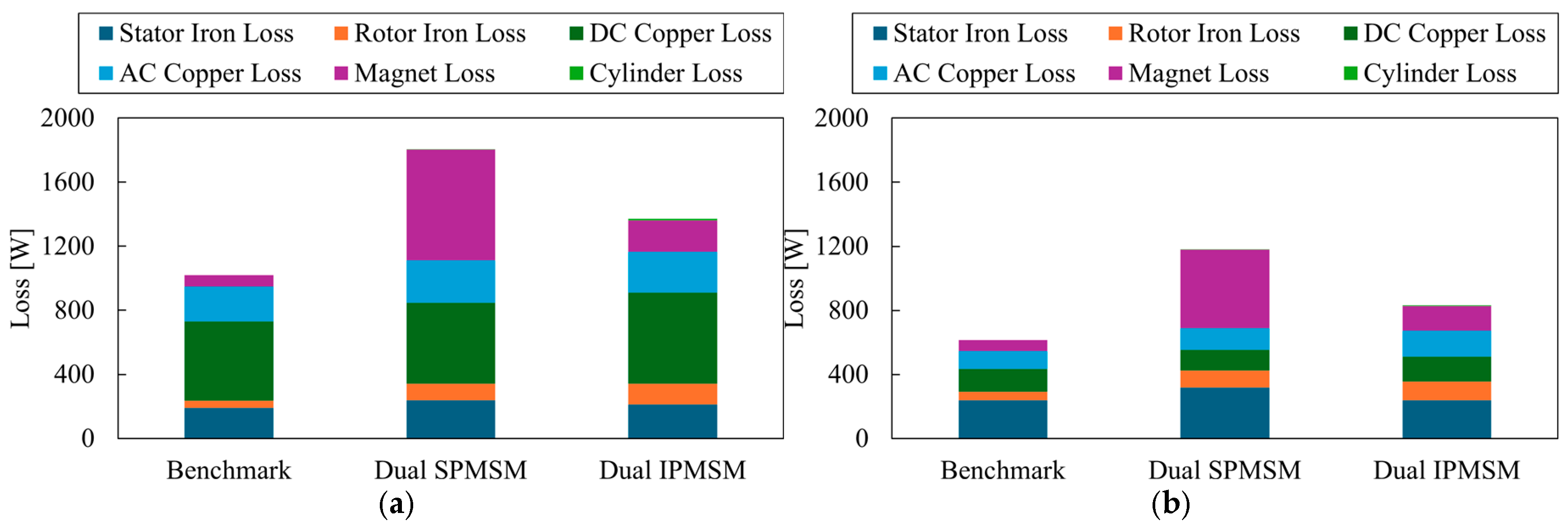
In general, PMSM exhibits higher efficiencies than Syn.RM and IM; however, the PMSM with aluminum winding achieves maximum efficiency comparable to that of the Syn.RM. To investigate the underlying reasons, a detailed loss analysis was carried out at two operating points: low-speed/high-load (2000 rpm, 100 Nm) and medium-speed/medium-load (4000 rpm, 50 Nm). The resulting loss comparison is presented in
Figure 14. Since the mechanical losses are identical at each operating point, the comparison focuses on stator and rotor iron losses, DC copper losses, AC copper losses, magnet losses, and eddy-current losses in the outer cylinder. The DC copper loss is calculated by multiplying the current by the winding resistance, while the AC copper loss is obtained by subtracting the DC copper loss from the total copper loss. Magnet segmentation is not considered in this analysis. From
Figure 14, it is evident that the benchmark motor exhibits the smallest losses at both operating points, whereas the Dual SPMSM shows the largest losses. Comparing the benchmark with the PMSMs with aluminum winding, both iron losses and magnet losses increase significantly. The increase in iron loss is attributed to the reduced cross-sectional area of the electrical steel, which is necessary to enlarge the slot area of the PMSMs with aluminum winding; this likely resulted in more severe magnetic saturation. Regarding magnet losses, the Dual IPMSM contains a larger magnet volume than the benchmark, and the Dual SPMSM not only uses a greater amount of magnet material but also places the magnets on the rotor surface, making it more susceptible to harmonic components of the air gap flux.
5.2. Calculation of Environmental Impact During the Use Stage
Using the simulation software KuLI @ Magna Powertrain INC., a driving simulation based on the efficiency maps in
Figure 13 is performed under the WLTC cycle [
16]. The vehicle parameters used in the simulations are listed in
Table 9, and the resulting energy consumption values are summarized in
Table 10. Based on the results in
Table 10, the electrical energy required to drive 150,000 km is calculated. By multiplying these values by the amount of
CO2 emitted to generate 1 kWh of electricity in Japan, as listed in
Table 11, the
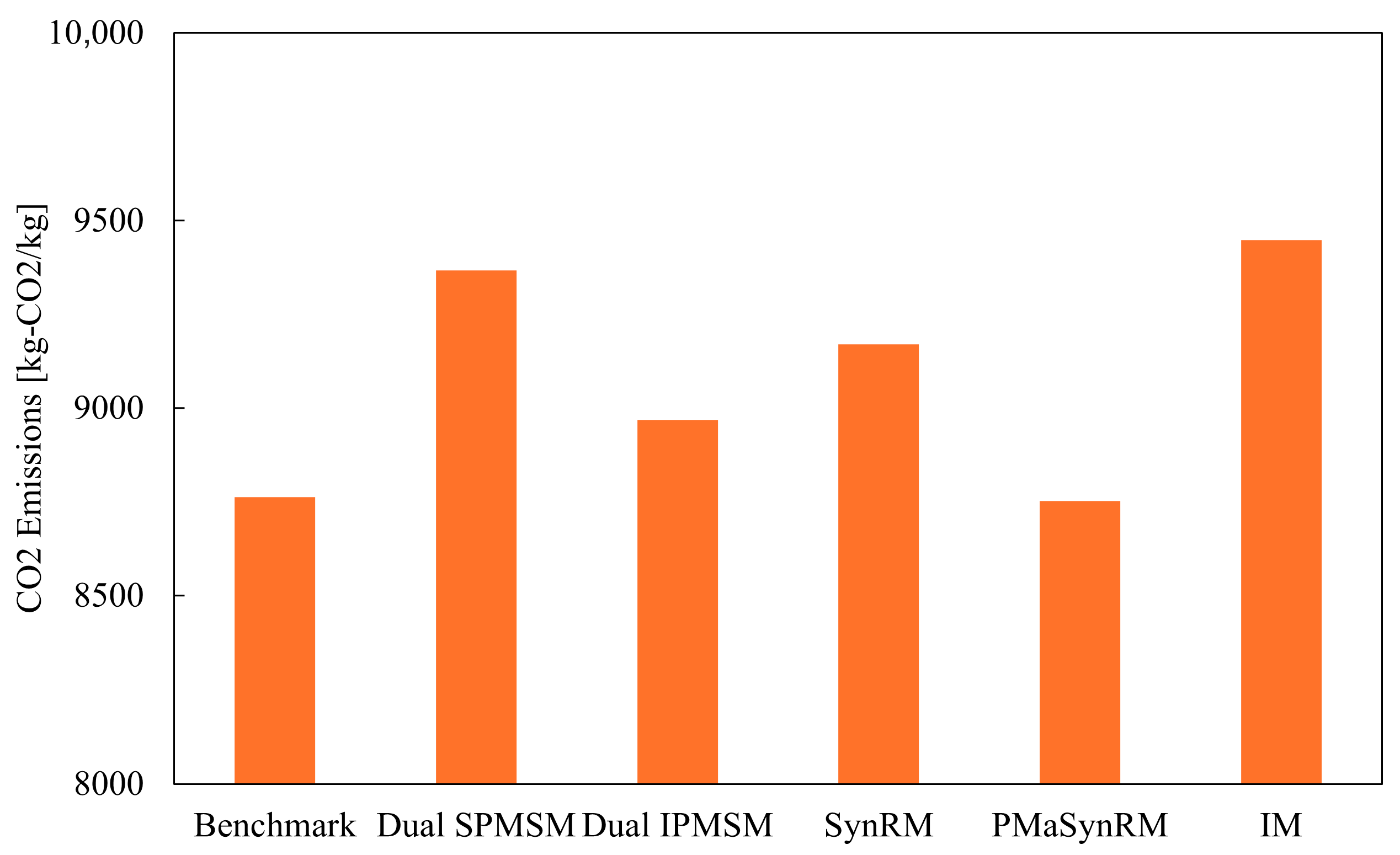
CO2 emissions during vehicle operation can be obtained. The comparison of operational
CO2 emissions is presented in
Figure 15, which serves as the evaluation of environmental impact during the use stage. It should be noted that the vehicle mass is assumed to be constant for all motor configurations, and the increase in vehicle mass due to the larger battery required for the Syn.RM increased power demand is not taken into account. From
Figure 15, it is evident that the benchmark motor and the PMaSyn.RM, both of which exhibit high efficiency, show lower environmental impact during use stage. Notably, the PMaSyn.RM—despite being a rare-earth-free motor—achieves an environmental impact comparable to that of the benchmark PMSM utilizing NdFeB magnets, demonstrating the potential of this motor type.
6. Limitations and Future Work
This study evaluates six motor configurations under unified design constraints and provides a comparative Life Cycle Assessment based on material composition and simulated performance. However, several limitations must be acknowledged. The analysis relies entirely on electromagnetic simulations, and no physical prototypes were fabricated or tested. As a result, real-world effects such as manufacturing tolerances, thermal degradation, mechanical vibration, and long-term reliability were not captured. In addition, the manufacturing-stage LCA focuses primarily on material production and does not include detailed process-level emissions from stamping, winding, bonding, or assembly, which may vary across motor types and influence the overall environmental impact. The use phase assessment is based on representative operating points rather than full driving-cycle integration, meaning that variations in efficiency under dynamic load conditions are not fully reflected.
Future work should address these limitations by incorporating prototype fabrication and experimental validation of torque, efficiency, and thermal behavior. A more detailed process-based LCA, including manufacturing steps and supply-chain variability, would improve the accuracy of the environmental assessment. Furthermore, integrating standardized driving cycles such as WLTC into the efficiency evaluation would enable a more realistic estimation of use-phase emissions. Long-term reliability studies, particularly for aluminum windings and dual-rotor structures, would also provide valuable insights into the practical feasibility of the proposed designs.
7. Conclusions
This study designed and evaluated six EV traction motors under identical geometric and electromagnetic constraints to clarify how winding materials, magnet configurations, and structural choices influence environmental performance across the motor life cycle. The results demonstrate that motors using NdFeB magnets, particularly the PMSM with copper winding, exhibit the highest manufacturing emissions due to the environmental burden associated with rare-earth magnet production. In contrast, PMSMs with aluminum winding and rare-earth-free designs such as PMaSyn.RM and Syn.RM significantly reduce manufacturing emissions, with the latter achieving the lowest values among all configurations. However, the use-phase assessment reveals that the PMSM with copper winding maintains the highest efficiency and therefore the lowest operational emissions, while aluminum winding and rare-earth-free motors experience higher losses that increase their use-stage impact. When manufacturing and use phases are combined, the optimal motor type depends strongly on the expected driving distance. For short-distance applications, where manufacturing emissions dominate, rare-earth-free motors such as PMaSyn.RM and Syn.RM offer the most environmentally favorable option. For long-distance EV usage, where operational efficiency becomes the primary contributor to total emissions, the PMSM with copper winding remains the most advantageous. These findings highlight the importance of selecting motor technologies based not only on performance but also on usage patterns and environmental priorities, and they provide a foundation for future sustainable motor design strategies.
Author Contributions
Conceptualization, K.A.; methodology, K.A.; software, D.W.; validation, K.A. and D.W.; formal analysis, D.W.; writing—original draft preparation, D.W.; writing—review and editing, K.A. All authors have read and agreed to the published version of the manuscript.
Funding
This research received no external funding.
Data Availability Statement
The original contributions presented in this study are included in the article. Further inquiries can be directed to the corresponding author.
Conflicts of Interest
The authors declare no conflict of interest.
References
- Ministry of Land, Infrastructure, Transport and Tourism (MLIT). CO2 Emissions from the Transport Sector. Available online: https://www.mlit.go.jp/sogoseisaku/environment/sosei_environment_tk_000007.html (accessed on 2 December 2025).
- Schipper, B.W.; Lin, H.-C.; Meloni, M.A.; Wansleeben, K.; Heijungs, R.; van der Voet, E. Estimating global copper demand until 2100 with regression and stock dynamics. Resour. Conserv. Recycl. 2018, 132, 28–36. [Google Scholar] [CrossRef]
- Memary, R.; Giurco, D.; Mudd, G.; Mason, L. Life cycle assessment: A time-series analysis of copper. J. Clean. Prod. 2012, 33, 97–108. [Google Scholar] [CrossRef]
- Hernandez, M.; Messagie, M.; Hegazy, O.; Marengo, L.; Winter, O.; Van Mierlo, J. Environmental impact of traction electric motors for electric vehicles applications. Int. J. Life Cycle Assess. 2017, 22, 54–65. [Google Scholar] [CrossRef]
- Schillingmann, H.; Gehler, S.; Henke, M. Life cycle assessment of electrical machine production considering resource requirements and sustainability. In Proceedings of the 2021 11th International Electric Drives Production Conference (EDPC), Erlangen, Germany, 7–9 December 2021; IEEE: Piscataway, NJ, USA, 2021; pp. 1–7. [Google Scholar] [CrossRef]
- Tintelecan, A.; Dobra, A.C.; Martis, C. Life Cycle Assessment Comparison of Synchronous Motor and Permanent Magnet Synchronous Motor. In Proceedings of the 2020 International Conference and Exposition on Electrical And Power Engineering (EPE), Iasi, Romania, 22–23 October 2020; IEEE: Piscataway, NJ, USA, 2020; pp. 205–210. [Google Scholar] [CrossRef]
- Orbay, R.; Singh, A.P.; Harsjo, J.; Thiringer, T.; Mademlis, G.; Larsson, D.; Bernichon, T. Sustainable Design and LCA of non-RE PMSynRM with Bioplastic Rotor Shroud. In Proceedings of the 2022 12th International Conference on Power, Energy and Electrical Engineering (CPEEE), Shiga, Japan, 25–27 February 2022; IEEE: Piscataway, NJ, USA, 2022; pp. 34–40. [Google Scholar] [CrossRef]
- Jerome, A.; Ljunggren, M.; Janssen, M. Is repair of energy using products environmentally bene- 441 ficial? The case of high voltage electric motors. Resour. Conserv. Recycl. 2023, 196, 107038. [Google Scholar] [CrossRef]
- Rassõlkin, A.; Belahcen, A.; Kallaste, A.; Vaimann, T.; Lukichev, D.V.; Orlova, S.; Heidari, H.; Asad, B.; Acedo, J.P. Life cycle analysis of electrical motor-drive system based on electrical machine type. Proc. Est. Acad. Sci. 2020, 69, 162–177. [Google Scholar] [CrossRef]
- Nordelöf, A.; Grunditz, E.; Lundmark, S.; Tillman, A.-M.; Alatalo, M.; Thiringer, T. Life cycle assessment of permanent magnet electric traction motors. Transp. Res. Part D 2019, 67, 263–274. [Google Scholar] [CrossRef]
- Akatsu, K.; Miyama, Y.; Takahashi, T.; Aiso, K. CO2 Evaluation in Life Cycle Assessment of Electric Machines Activities. In Proceedings of the 2025 Annual Meeting IEE of Japan, Nakano, Tokyo, 18–20 March 2025. [Google Scholar]
- Widmer, J.D.; Martin, R.; Mecrow, B.C. Precompressed and Stranded Aluminum Motor Windings for Traction Motors. IEEE Trans. Ind. Appl. 2016, 52, 2215–2223. [Google Scholar] [CrossRef]
- Sugimoto, H.; Yamada, Y.; Imae, K. Analysis of Winding AC Loss in a Permanent Magnet Synchronous Machine With High Slot Fill Aluminum Winding. In Proceedings of the 2022 International Power Electronics Conference (IPEC-Himeji 2022-ECCE Asia), Himeji, Japan, 15–19 May 2022; IEEE: Piscataway, NJ, USA, 2022; pp. 2741–2745. [Google Scholar] [CrossRef]
- Qu, R.; Lipo, T.A. Design and parameter effect analysis of dual-rotor, radial-flux, toroidally wound, permanent magnet machines. IEEE Trans. Ind. Appl. 2004, 40, 771–779. [Google Scholar] [CrossRef]
- Zhang, Z. A Compact High Torque Density Dual Rotor Permanent Magnet In-Wheel Motor With Toroidal Windings. In Proceedings of the 2019 22nd International Conference on Electrical Machines and Systems (ICEMS), Harbin, China, 11–14 August 2019; IEEE: Piscataway, NJ, USA, 2019; pp. 1–5. [Google Scholar] [CrossRef]
- United Nations Economic Commission for Europe (UNECE). UN Global Technical Regulation No. 15 (WLTP) (ECE/TRANS/180/Add.15). Available online: https://unece.org/fileadmin/DAM/trans/main/wp29/wp29r-1998agr-rules/ECE-TRANS-180a15e.pdf (accessed on 16 February 2026).
Figure 1.
Copper winding PMSM model.
Figure 1.
Copper winding PMSM model.
Figure 2.
Copper winding PMSM model current advanced angle vs. torque characteristics, 240. A peak current is added to a phase. The maximum magnet torque is 80 Nm, and almost the same reluctance torque is output.
Figure 2.
Copper winding PMSM model current advanced angle vs. torque characteristics, 240. A peak current is added to a phase. The maximum magnet torque is 80 Nm, and almost the same reluctance torque is output.
Figure 3.
A schematic diagram of structural change for the aluminum motor.
Figure 3.
A schematic diagram of structural change for the aluminum motor.
Figure 4.
Aluminum winding PMSM model: (a) SPMSM Type. (b) IPMSM Type.
Figure 4.
Aluminum winding PMSM model: (a) SPMSM Type. (b) IPMSM Type.
Figure 5.
Aluminum winding PMSM model current advanced angle vs. torque characteristics. A peak current is added to one phase. (a) SPMSM Type. (b) IPMSM Type. (a) SPMSM Type shows the outer rotor outputs of only the magnet torque, that is why the magnet amount of (a) is larger than the amount of (b).
Figure 5.
Aluminum winding PMSM model current advanced angle vs. torque characteristics. A peak current is added to one phase. (a) SPMSM Type. (b) IPMSM Type. (a) SPMSM Type shows the outer rotor outputs of only the magnet torque, that is why the magnet amount of (a) is larger than the amount of (b).
Figure 6.
Copper winding Syn.RM model. The stack length is increased to meet with the output torque of the benchmark. The stator construction is the same as the benchmark, the flux barrier is optimized to output the maximum torque.
Figure 6.
Copper winding Syn.RM model. The stack length is increased to meet with the output torque of the benchmark. The stator construction is the same as the benchmark, the flux barrier is optimized to output the maximum torque.
Figure 7.
Copper winding Syn.RM current advanced angle vs. torque characteristics, 270. A peak current which is a larger current than an IPMSM current is added to one phase to output the same torque as the benchmark.
Figure 7.
Copper winding Syn.RM current advanced angle vs. torque characteristics, 270. A peak current which is a larger current than an IPMSM current is added to one phase to output the same torque as the benchmark.
Figure 8.
Copper winding PMaSyn.RM model. The ferrite magnets are used instead of NdFeB magnets, the stack length takes longer to output the same torque as the IPMSM.
Figure 8.
Copper winding PMaSyn.RM model. The ferrite magnets are used instead of NdFeB magnets, the stack length takes longer to output the same torque as the IPMSM.
Figure 9.
Copper winding PMaSyn.RM current advanced angle vs. torque characteristics. The magnet torque is relatively small, 42 Nm, and much reluctance torque is obtained by the layered magnet placements.
Figure 9.
Copper winding PMaSyn.RM current advanced angle vs. torque characteristics. The magnet torque is relatively small, 42 Nm, and much reluctance torque is obtained by the layered magnet placements.
Figure 10.
Copper winding IM model. The stator and rotor dimensions are the same as the benchmark. Aluminum is used for rotor bars.
Figure 10.
Copper winding IM model. The stator and rotor dimensions are the same as the benchmark. Aluminum is used for rotor bars.
Figure 11.
Slip vs. torque characteristics of IM. 240. A phase current is added to one phase, the rotation speed is 5000 rpm.
Figure 11.
Slip vs. torque characteristics of IM. 240. A phase current is added to one phase, the rotation speed is 5000 rpm.
Figure 12.
CO2 emissions at manufacturing stage. (Pri) means primary aluminum and (Rec) means recycled aluminum.
Figure 12.
CO2 emissions at manufacturing stage. (Pri) means primary aluminum and (Rec) means recycled aluminum.
Figure 13.
Efficiency Map: The maps are calculated by using FEA and iron loss calculation. The frequently used area by running a WLTC cycle is overlayed on the map.
Figure 13.
Efficiency Map: The maps are calculated by using FEA and iron loss calculation. The frequently used area by running a WLTC cycle is overlayed on the map.
Figure 14.
PMSM Loss Comparison: (a) 2000 rpm, 100 Nm. (b) 4000 rpm, 50 Nm.
Figure 14.
PMSM Loss Comparison: (a) 2000 rpm, 100 Nm. (b) 4000 rpm, 50 Nm.
Figure 15.
CO
2 emissions at use stage. The value is in proportion to the energy consumption in
Table 9 because the output of CO
2 emissions per kWh in
Table 10 is commonly used.
Figure 15.
CO
2 emissions at use stage. The value is in proportion to the energy consumption in
Table 9 because the output of CO
2 emissions per kWh in
Table 10 is commonly used.
Table 1.
Comparison of magnet quantity by rotor structure changes.
Table 1.
Comparison of magnet quantity by rotor structure changes.
| Models | Inner Magnet Amount | Outer Magnet Amount | Total Magnet Amount |
|---|
| | mm3 | mm3 | mm3 |
|---|
| SPMSM | 72,000 | 75,000 | 147,000 |
| IPMSM | 72,000 | 65,000 | 137,000 |
Table 2.
Densities of materials.
Table 2.
Densities of materials.
| Materials | Density [g/(mm3)] |
|---|
| Copper | 0.00896 |
| Aluminum | 0.0027 |
| Electrical Steel | 0.00765 |
| NdFeB Magnet | 0.0076 |
| Ferrite Magnet | 0.00512 |
| S45C | 0.0078 |
Table 3.
Motor mass. The mass is calculated from the 3D motor models, and masses were calculated using material densities from
Table 2. The winding mass was computed from the conductor cross-section, number of turns, and average turn length.
Table 3.
Motor mass. The mass is calculated from the 3D motor models, and masses were calculated using material densities from
Table 2. The winding mass was computed from the conductor cross-section, number of turns, and average turn length.
| Materials | Benchmark | Dual | Dual | Syn.RM | PMaSyn.RM | IM |
|---|
| | SPMSM | IPMSM | |
|---|
| Copper [kg] | 3.836 | 0 | 0 | 4.22 | 4.013 | 3.836 |
| Aluminum [kg] | 0 | 1.741 | 1.535 | 0 | 0 | 0.296 |
| Electrical Steel [kg] | 12.307 | 10.787 | 10.662 | 14.731 | 14.108 | 11.238 |
| NdFeB Magnet [kg] | 0.55 | 1.115 | 1.04 | 0 | 0 | 0 |
| Ferrite Magnet [kg] | 0 | 0 | 0 | 0 | 1.003 | 0 |
| S45C [kg] | 0 | 0 | 0.624 | 0 | 0 | 0 |
| Total [kg] | 16.692 | 13.643 | 13.861 | 18.951 | 19.125 | 15.37 |
Table 4.
Electrical steel mass for manufacturing.
Table 4.
Electrical steel mass for manufacturing.
| Models | Mass [kg] |
|---|
| Benchmark | 29.747 |
| Dual SPMSM | 28.821 |
| Dual IPMSM | 28.821 |
| Syn.RM | 39.447 |
| PMASyn.RM | 34.224 |
| IM | 29.747 |
Table 5.
Material costs.
| Materials | Cost [$] |
|---|
| Copper | 11.7 |
| Aluminum | 3.0 |
| Steel | 2.0 |
| NdFeB Magnet | 53.3 |
| Ferrite Magnet | 6.7 |
| S45C | 1.3 |
Table 6.
Motor material costs.
Table 6.
Motor material costs.
| Materials | Benchmark | Dual SPMSM | Dual IPMSM | SynRM | PMaSynRM | IM |
|---|
| Copper [$] | 44.8 | 0 | 0 | 49.2 | 46.8 | 44.8 |
| Aluminum [$] | 0 | 5.2 | 4.6 | 0 | 0 | 0.9 |
| Electrical Steel [$] | 59.5 | 57.6 | 57.6 | 78.9 | 68.4 | 59.5 |
| NdFeB Magnet [$] | 29.3 | 59.5 | 55.5 | 0 | 0 | 0 |
| Ferrite Magnet [$] | 0 | 0 | 0 | 0 | 6.7 | 0 |
| S45C [$] | 0 | 0 | 0.8 | 0 | 0 | 0 |
| Total [$] | 133.4 | 122.3 | 118.6 | 128.1 | 122.0 | 105.1 |
Table 7.
CO
2 emissions of materials [
11].
Table 7.
CO
2 emissions of materials [
11].
| Materials | CO2 Emissions [kg-CO2/kg] |
|---|
| Copper | 3 |
| Aluminum (Primary) | 12 |
| Aluminum (Recycled) | 0.4 |
| Electrical Steel | 2.3 |
| NdFeB Magnet | 40 |
| Ferrite Magnet | 4.22 |
| S45C | 1.63 |
Table 8.
Efficiency map evaluation parameters. Syn. RM has lower power factor characteristics resulting in high voltage and high current which are required to obtain the same output power as the other machines.
Table 8.
Efficiency map evaluation parameters. Syn. RM has lower power factor characteristics resulting in high voltage and high current which are required to obtain the same output power as the other machines.
| Parameters | Value |
|---|
| DC Voltage excluding Syn.RM [V] | 750 |
| Phase Current excluding Syn.RM [A] | 240 |
| Syn.RM DC Voltage [V] | 1000 |
| Syn.RM Phase Current [A] | 270 |
| Career Frequency [kHz] | 10 |
| Mechanical Loss [W/krpm] | 20 |
Table 9.
Driving simulation parameters for the driving simulation by KULI.
Table 9.
Driving simulation parameters for the driving simulation by KULI.
| Parameters | Value |
|---|
| Vehicle Mass [kg] | 1500 |
| Transmission Ratio | 7.2 |
| Drag Coefficient | 0.27 |
Table 10.
Energy consumption comparison of WLTC cycle.
Table 10.
Energy consumption comparison of WLTC cycle.
| Motors | Energy Consumption [km/kWh] |
|---|
| Benchmark | 7.019 |
| Dual SPMSM | 6.565 |
| Dual IPMSM | 6.857 |
| Syn.RM | 6.707 |
| PMaSyn.RM | 7.027 |
| IM | 6.509 |
Table 11.
CO2 emissions associated with generating 1 kWh of electricity based on the Japanese energy mix.
Table 11.
CO2 emissions associated with generating 1 kWh of electricity based on the Japanese energy mix.
| Parameter | Value |
|---|
| CO2 Emissions [kg-CO2/kg] | 0.41 |
| Disclaimer/Publisher’s Note: The statements, opinions and data contained in all publications are solely those of the individual author(s) and contributor(s) and not of MDPI and/or the editor(s). MDPI and/or the editor(s) disclaim responsibility for any injury to people or property resulting from any ideas, methods, instructions or products referred to in the content. |
© 2026 by the authors. Published by MDPI on behalf of the World Electric Vehicle Association. Licensee MDPI, Basel, Switzerland. This article is an open access article distributed under the terms and conditions of the Creative Commons Attribution (CC BY) license.