Article

Torque Smoothness for a Modified W-Type Inverter-Fed Three-Phase Induction Motor with Finite Set Model Predictive Control for Electric Vehicles

by
Muhammad Ayyaz Tariq
1,*,
Syed Abdul Rahman Kashif
1,
Akhtar Rasool
2,* and
Ahmed Ali
3
1
Department of Electrical Engineering, University of Engineering and Technology, Lahore 54890, Pakistan
2
Department of Electrical Engineering, University of Botswana, Gaborone UB0061, Botswana
3
Department of Electrical and Electronic Engineering Technology, University of Johannesburg, Johannesburg 2092, South Africa
*
Authors to whom correspondence should be addressed.
World Electr. Veh. J. 2025, 16(9), 539; https://doi.org/10.3390/wevj16090539
Submission received: 29 June 2025 / Revised: 12 August 2025 / Accepted: 15 August 2025 / Published: 22 September 2025

Abstract

Ripples in the electromagnetic torque of electric vehicle (EV) motors due to poor stator voltage and control cause jerky movements, equipment failure, discomfort for passengers and drivers, and damage to the associated civil works. This paper presents the implementation of Finite Control Set Model Predictive Control (FCSMPC) for a high-level modified W-type inverter (MWI) driving a three-phase induction motor (IM), along with validation of its performance. The proposed control strategy aims to minimize motor torque ripples and has been tested under various driving torque patterns. The results demonstrate a significant reduction in torque ripples—down to less than 1%—and acceptable levels of total harmonic distortion (THD), as verified through quality analysis of the stator currents. Moreover, a comparative assessment of voltage profiles for the electromagnetic torque and rotor speed curves has been presented for nine cases of simultaneous variations in multiple motor parameters; the results indicate that the MWI-fed motor has the best performance and the lowest sensitivity to the variations.

1. Introduction

Increasing modernization and a drastic and continuous increase in the population have deteriorated the environment. The use of energy sources that damage the environment is being strongly discouraged as the global perspective on pollution has become uncompromising. On the same account, the demand for electric vehicles (EVs) has increased manifold in the last two decades. Features of a good EV motor include suitable dynamic performance, robust behavior, a wide speed range, high power density, etc., as described in [1].
Torque response is very important in the acceleration and deceleration of a vehicle. Motor torque ripples cause vibrations, resulting in discomfort for the driver as well as the passengers. The effective life of the vehicle is reduced by the negative impacts of these ripples on the transmission and suspension systems [2]. The ripples must be minimized to lessen the vibration and noise levels and to increase the life span of the vehicle [3]. Discomfort in the human body is documented, along with psychological strain and other health-related issues caused by prolonged exposure to vibrations, in [4]. Additional consequences include failures or malfunctions of motors used in vehicles, cranes, and elevators; instabilities in wind turbine–generator systems; inaccuracies in motion control; and reduced precision in micro-scale structures. Furthermore, vibrations can contribute to the deterioration of civil infrastructure associated with transportation systems, as noted in [5].
Further details regarding EV motors, including their advantages and drawbacks and the causes of ripples, are listed later in this section. Moreover, the recent inverter topologies and important control strategies described in the literature are briefly summarized for the readers. The motor design and control techniques deployed for the solution of the discussed problem are also mentioned, along with their shortcomings.
Different types of motors are used in different proportions for EVs. Various motors, namely, DC motor (DCMs), induction motor (IMs), switched reluctance motor (SRMs), AC and DC versions of permanent-magnet (PM) brushless motors, and in-hub brushless DC (BLDC) motors used in EVs have been compared in terms of loading capacity, losses, and torque–speed characteristics in the literature. The benefits of IMs are constant torque and power, high maximum speed, global availability, ruggedness, robust behavior, enhanced power density, and consistent operation over a wide speed range. These motors been deployed in various EVs, including the Audi e-tron Quattro and the Mercedes-Benz EQC [1].
Load disturbances, current discontinuation, uncertain parameter variations, and free-wheeling current during conduction through a diode may cause large torque ripples in BLDC motors [6,7]. The harmonics of the armature currents and the spatial harmonics of the magnetic field are the reasons for their occurrence in permanent-magnet synchronous motors (PMSMs), where they result in mechanical vibrations and acoustic noise [8]. In SRMs, torque production has a non-linear and discrete nature that accentuates the ripples and thus creates an undesirable response in servo applications such as electric vehicles [9,10,11]. Magnetic flux saturation in interior-permanent-magnet synchronous motors (IPMSMs) [12], non-uniform torque in synchronous reluctance motors (SynRMs) [13], and reduced friction of electric propulsion systems [14] may result in undesirable oscillatory behavior.
Torque ripples in IMs are caused by several factors, including harmonic content in the supply voltage and the non-sinusoidal distribution of stator windings. It is well known that a better-quality voltage output waveform is provided by multilevel inverters (MLIs) than by low-level inverters, which provide a sine-wave current. Low-level inverters generate significant harmonics, which reduce system efficiency and lead to excessive heating. In contrast, MLIs enable precise voltage synthesis, ensuring improved stator voltage quality. This enhancement contributes to better torque profiles and improved transient response [15]. Additional advantages of MLIs include smoother frequency control, enhanced control performance, reduced component stress, and lower harmonic distortion [15,16].
Various parameters to assess, compare, and classify inverters, such as component count, average number of active switches, total blocking voltage, level and polarity generation, number of output voltage levels, single or multistage design, switching frequency, source symmetry, circulating currents, inclusion of transformers and commutation, power loss, and modularity, have been mentioned in the literature [17,18,19,20,21,22]. Some of the recent topologies include single-stage switched capacitor module topology [23], modified K-type inverters with an H-bridge [24], configurable topology [25], switched-capacitor-based self-balanced step-up MLIs [26], extended topology [27], compact three-phase MLIs [28], Qn-hybrid-NPC design [29], modified W-type inverter (MWI) [30], cascaded with symmetric and asymmetric sources [31], and cross-connected source-based inverters [32]. Cascaded H-bridge (CHB) topology [33] has also existed for several years.
MLIs are currently the dominant option proposed for low- and high-power applications as well as traction drives [34]. The technical aspects of this trend include reduced voltage stress for switches and motor windings, smoother motor operation, better reliability with modularity, a lesser voltage gradient, etc. The economic benefits offered by MLIs pay back their relatively high initial cost. These benefits include the reduced cost of lower-voltage-rating switches, higher efficiency, non-utilization of filters, lesser maintenance requirements, and a longer service life for motors and related equipment. Additionally, MWI gives increased output voltage levels with lower component counts, the ability to use DC sources with different voltages, and better total standing voltage and efficiency [30,35]. Moreover, MWI offers the lowest component count per level among various inverter topologies [35].
Control methodologies play a pivotal role in the performance of EV motors. The literature mentions hybrid modulation, proportional–integral–derivative control (PIDC) [36], voltage–frequency control (VFC) [36], power quality control (PQC) [36], selective harmonic elimination (SHE) and fault tolerance [37], DC-link voltage balancing using modulation [38], maximum power point tracking (MPPT) [33], voltage-oriented control (VOC) [39], direct torque control (DTC) [40], H-infinity control (HC) [36], sliding mode control (SMC) [41], direct current control (DCC) [18], predictive current control (PCC) [18], finite control set model predictive control (FCSMPC) [18], and hysteresis-based control [18]. Exhaustive calculation and overdependence on controller gains make the implementation of classical control cumbersome [42]. A similar limitation regarding complex gain optimization has been observed for PIDC, despite the simplicity of its structure [36]. In [36], the voltage and frequency of islanded microgrids are adjusted via VFC, with PQC handling the real and reactive power of on-grid microgrids. An unsatisfactory transient response, the inverter’s existing circulating currents, and voltage–frequency deviations have been noted as their drawbacks [36]. VOC executes decoupled control of currents in d–q co-ordinates [39] with two main shortcomings: the need for modulation and the limitations of the controller [43]. Performance reduction at lower speeds [40], and increased ripples in torque and flux profiles are listed as the disadvantages of DTC [44], whereas model predictive torque control shows a better dynamic response and quicker voltage selection. SMC controls the system through appropriate switching strategy selection to keep it on the sliding surface where the system shows the desirable features [41]. Although SMC displays a robust response and has relatively low computational costs, it faces a chattering problem [36]. The control loops and problem handling with linear matrix inequality ensure improved power quality along with performance and transient stability for HC in dealing with uncertainties and external disturbances [36]. The drawbacks of HC include its impracticality for larger system dimensions and the requirement of extensive and in-depth understanding of the system [36].
Ease of implementation, quickness of response, ability to deal with non-linearities, and inclusion of constraints in the objective function have made model predictive control (MPC) a widely adopted control technique for motor drives. In FCSMPC, the cost function is evaluated for a finite number of switching states of the inverter by using its discrete nature without the need for a modulator [45]. The issue of exhaustive search related to FCSMPC can be mitigated by eliminating the redundancy of the switching states and using an s-factor scheme [46,47,48]. The categorization of control techniques is portrayed in Figure 1 [49].
The control of IMs through MPC, its variants, and other related strategies is well reported in the literature [50,51,52]. These methods have also been deployed in traction drives and other electric vehicle applications for different motors [53,54,55]. A reduction in torque ripples has become pivotal for improving traction motors’ performance in railways, wheelchairs, and various other applications [56,57,58,59]. Vibration reduction for different motors has been achieved via Kalman filter theory, PIDC theory, and fuzzy control theory [60]; feedforward and feedback control [61]; the commutation and control method [62]; the zero-voltage excitation method [63]; and current chopping control [63]. Improved DTC [64], along with harmonic injection and optimization methods [65,66], has recently been discussed in the literature, and a review of various techniques is provided in [67]. The limitations of the various already-applied methods include reliance on linearity of models; a need for tuning and precise modeling; computational complexity; dependency on human intervention; sensitivity to external disturbances; increased risks of mechanical damage, power losses, and maintenance costs; limited torque and speed ranges, increased harmonics; and reduced efficiency.
In this research, FCSMPC is applied to MWI-fed IM drive for EVs where the most suited switching state is the actuation to the inverter. Motor control is carried out so as to follow the required values of torque profiles while minimizing ripples and, hence, unwanted vibrations. Here, the significance of inverter design, inverter control, and voltage waveform quality is highlighted. This paper proposes and discusses strategies that achieve the following:
  • Evaluate the impact of the quality of voltage profiles on rotor speed and electromagnetic torque for motors. Two motors of different ratings are deployed for better generalization of applications.
  • Comparatively assess rotor speed and electromagnetic torque ripples for simultaneous variations in multiple motor parameters. The motors are fed with three different voltage profiles for this purpose, and nine sets of variations have been presented.
  • Validate the performance of FCSMPC for minimization of ripples, combined with the significance of the voltage quality supplied by an MWI for different driving torque patterns. The quality of stator currents is also analyzed.
The problem statement and control methodology are further discussed in Section 2 and Section 3, respectively. Section 4 documents the results and discussion; the article is concluded in Section 5.

2. Problem Statement

Torque ripples and sudden load changes cause damaging vibrations and unwanted speed fluctuations leading to faulty operation of vehicles, financial loss, and human discomfort. Some of the other consequences include instability and lack of precision in motor-based applications. The minimization of these vibrations results in an extended service life for vehicles, comfort for passengers, and a reduction in malfunction risks.
Switch failures affect the voltage, current, and torque profiles in conventional inverters and may cause speed and torque variations. In the quest to obtain desired torque profiles, the control of IM drives in EVs has risen to a pivotal role. Smooth torque and speed acceleration and deceleration are the major requirements of EVs. An MWI provides more levels in its voltage waveform, resulting in better stator voltage acquisition and assisting in the minimization of ripples through proper control. In FCSMPC, the most appropriate stator voltage vector is applied to MWI-based three-phase IM to follow the reference driving torque pattern with reduced vibrations. The cost function minimizes the absolute error between the reference and predicted values of torque, T e * and T e p , respectively, for the upcoming instant, k + 1 . The error function is as follows:
| T e * ( k + 1 ) T e p ( k + 1 ) |
The quality of the stator phase currents is also analyzed. The ripples in the torque profiles are recorded and compared to the results presented in the literature. Another portion of the problem statement evaluates the impacts of voltage quality provided by different inverter topologies under simultaneous variations in motor parameters. The upcoming section explains the methodology and terms used in the FCSMPC procedure to attain the predicted torque value.

3. Methodology

MPC applies the first actuation from the attained solution sequence and repeats the process; multiple objectives can be handled [42,45,68]. The impact of the independent variables (controller’s outputs) on the dependent variables (plant’s outputs) is also predicted [25]. The optimization is performed over a limited horizon, and minimization of the cost function gives the optimized control output (control action), which is applied at that instant [45].
The continuous and finite control set variants of MPC provide an improved dynamic response and increased controllability for IMs and converters [42,69,70,71]. FCSMPC starts by linking the relevant IM quantities with the switching states of the inverter. In the presented strategy, the optimal actuation for MWI is chosen from a finite set of switching states. It evaluates the cost function for each candidate voltage vector by deploying the discrete nature of the system components. Estimations, measurements, and predictions related to the stator and rotor currents, fluxes, rotor speed, and electromagnetic torque are involved in its implementation. The estimated rotor flux is updated on the basis of its existing value, stator current measurements, speed, and other motor parameters, followed by stator flux and torque estimation [72].
ϕ s ^ ( k ) = L m L r ϕ r ^ ( k ) + σ L s i s ( k )
T e ^ ( k ) = c p m p ( ϕ s ^ ( k ) · i s ( k ) )
The next step is to predict the direct and quadrature components of stator currents and fluxes, which are further deployed to predict the electromagnetic torque. This prediction step is based on current measurements, flux estimations, and the stator voltage vector of the previous control period [46,72,73].
( ϕ s p ( k + 1 ) = ϕ s ^ ( k ) + T s v s ( k ) T s R s i s ( k ) )
i s p ( k + 1 ) = ( 1 + T s τ σ ) i s ( k ) + [ ( T s τ σ + T s ) × [ 1 R σ ( k r τ r k r j ω e ( k ) ) ϕ r ^ ( k ) + v s ( k ) ]
T e p ( k + 1 ) = c p m p ( ϕ s p ( k + 1 ) · i s p ( k + 1 ) )
In the above equations ϕ s ^ , ϕ r ^ , and i s represent the estimated stator and rotor flux and measured stator current vectors, respectively, having direct and quadrature components. k denotes the current instant. L m represents the mutual inductance; L r represents the rotor inductance; σ represents the leakage factor and is equal to 1 [ L m 2 / ( L s L r ) ] , where L s represents the stator inductance. T e ^ is the estimated electromagnetic torque, c is a constant, p denotes the number of pole pairs, and m p stands for the constant dependent on the motor parameters. Additionally, ϕ s p and i s p represent the predicted stator flux and current vectors, which have direct and quadrature components; T s is the sample time; v s is the stator voltage vector, which has direct and quadrature components; R s is the stator resistance; and T e p is the predicted electromagnetic torque. Here, k r = L m / L r , R σ = R s + k r 2 R r , τ σ = L σ / R σ , L σ = σ L s , and τ r = L r / R r . Moreover, ω e is the electrical speed of the rotor. A flowchart of the process is shown in Figure 2.
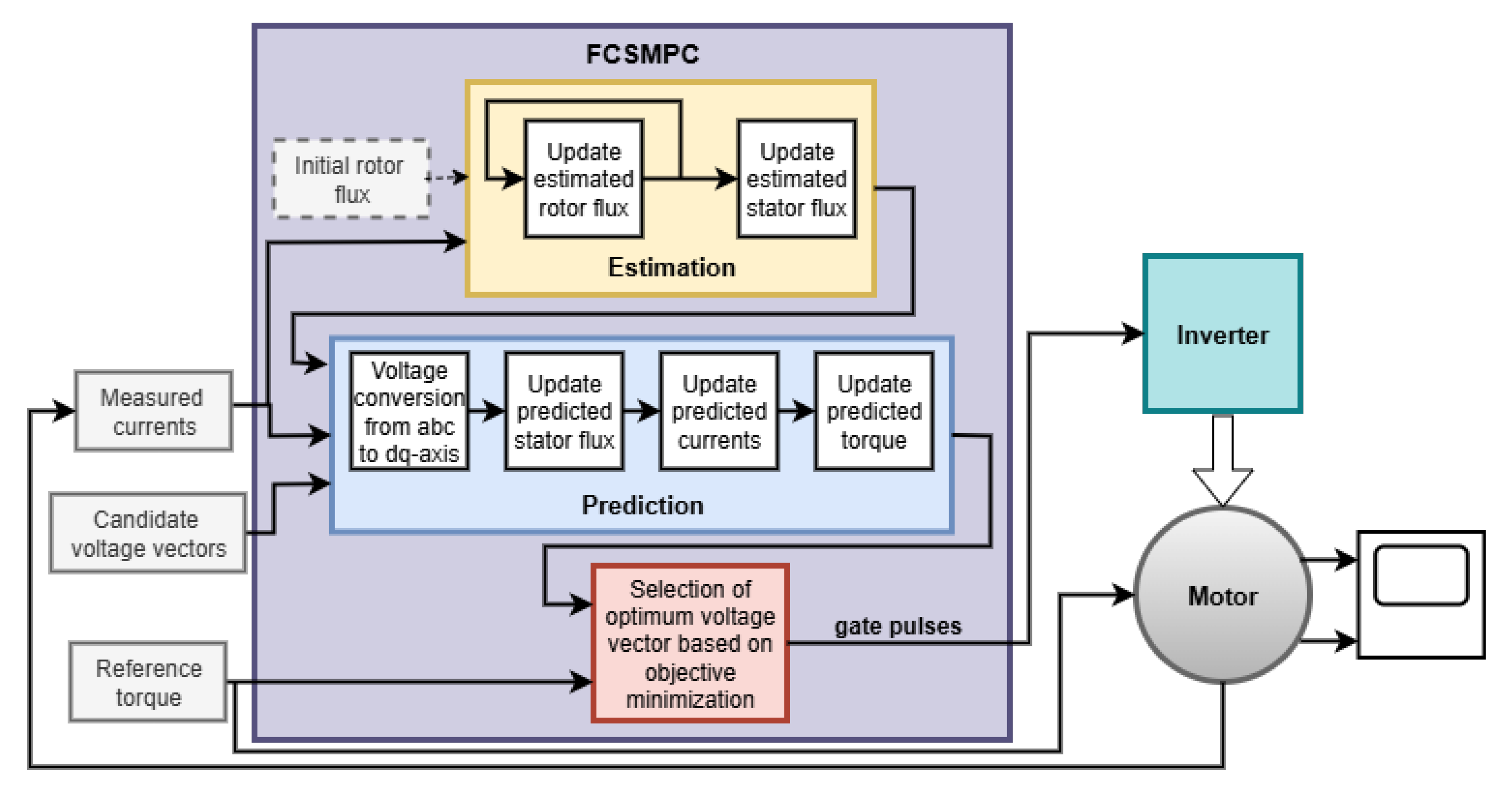
The setup for the implementation of the FCSMPC equations and the methodology of torque error minimization is shown in Figure 3.
In Figure 3, the candidate voltage vectors represent the gating pulse combinations corresponding to the various possible switching states of the inverter. These combinations can either be provided as external inputs or be defined within the SIMULINK programming block. The sampling time, frequency, motor parameters, and other constants necessary for computation are embedded within the program (not shown in the figure to maintain its clarity). The measured direct and quadrature axis stator currents are taken as inputs from the motor, while the reference torque serves as the driving profile to be tracked or predicted. The FCSMPC block performs the estimation, prediction, and cost function evaluation to determine the optimal gating signals. These signals are then sent to the MWI to control the motor operation accordingly. The resulting rotor speed and electromagnetic torque profiles are recorded for performance analysis.
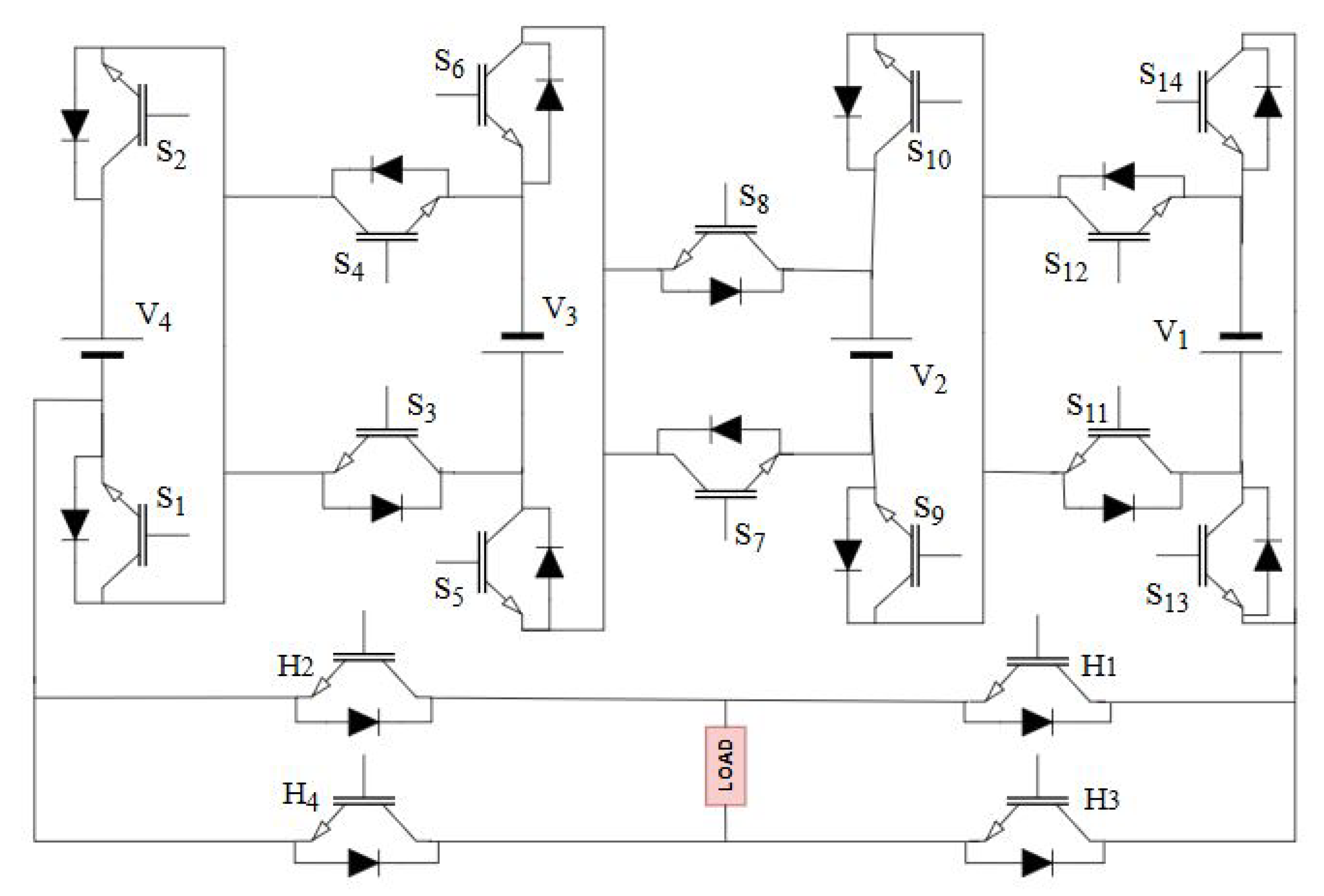
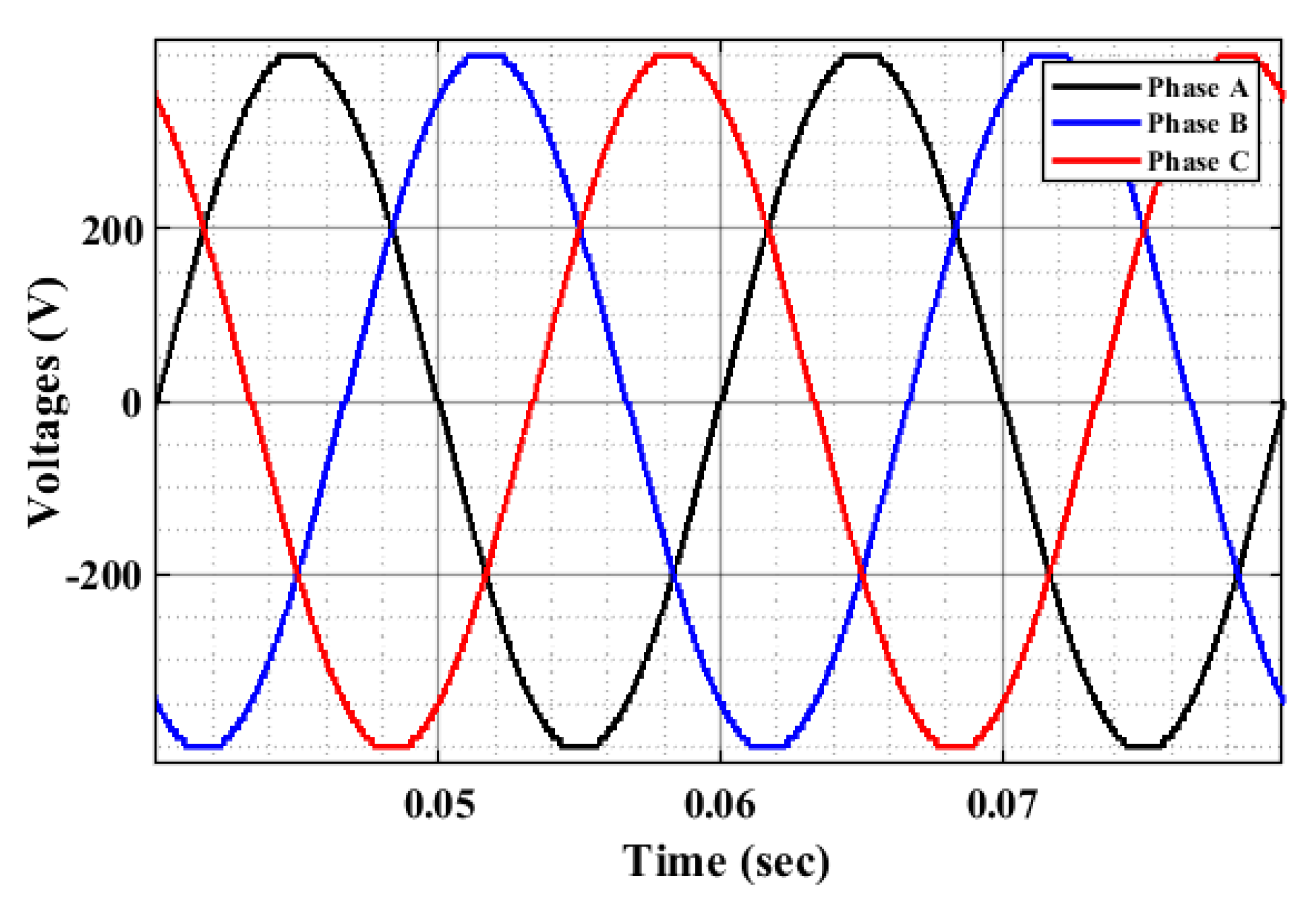
The circuit diagram for the MWI is shown in Figure 4, and its typical voltage waveform is presented in Figure 5 for DC source values of V 1 = 10 V, V 2 = 30 V, V 3 = 90 V, and V 4 = 270 V.
The single-phase voltage waveform of MWI contains 81 different levels of voltage. Switches S 1 and S 2 , S 3 and S 4 , S 5 and S 6 , S 7 and S 8 , S 9 and S 10 , S 11 and S 12 , and S 13 and S 14 operate in a complementary manner. The other four switches change the polarity of the stepped voltage waveform. The firing angles and duty cycles of the switches control their activation time points and durations of operation, respectively.
Motors with different power ratings were utilized to cover a broad spectrum of motor usage scenarios: while traction applications may demand high-power motors, light-duty vehicles typically utilize lower-power motors. This selection supports the generalization of the proposed method by validating its performance across a range of applications and motor models. The parameters of the motors deployed for the setup on MATLAB/SIMULINK 2023a (v 9.14) are listed in Table A1 and Table A2 of Appendix A.

4. Results and Discussion

The impacts of inverter quality and variation of motor parameters on the speed and torque profiles are detailed in the first subsection, and the performance of FCSMPC applied to the setup discussed above for multiple driving torque patterns is documented in the second subsection of this section.

4.1. Impact of Inverter Quality

The setup used in this subsection to evaluate the impact of inverter quality does not include the FCSMPC block. The default parameters of the selected motors are listed in the appendix. Three different qualities of stator voltage are supplied at their input terminals with small step load torque and no control algorithm. Multiple motor parameters are varied simultaneously for this open-loop system, and the results are presented.
The switching angles for MWI have been attained by digital conversion of sinusoidal waves into the number of voltage steps available in its typical output waveform [74]. The remaining two voltage profiles under consideration belong to the eleven-level CHB (CHB11) inverters, differing in their switching angles. The selected inverter topologies involve an approximately equal number of switches in their configurations [74]; however, the MWI operates at a significantly higher switching frequency. The first scenario (scenario 1) of the CHB11 inverter has five firing angles, α 1 = 0 . 1675 r , α 2 = 0 . 3399 r , α 3 = 0 . 5236 r , α 4 = 0 . 7298 r , and α 5 = 0 . 9852 r , while the second one (scenario 2) has α 1 = 0 . 02 r , α 2 = 0 . 43 r , α 3 = 0 . 61 r , α 4 = 1 . 06 r , and α 5 = 1 . 57 r [75]. These cases cover different voltage qualities from the same topology. In comparison to [74], two motors of considerably different ratings are considered here, with comparative assessment through nine cases of simultaneous variations in multiple parameters.
The first case represents the default parameter settings. The second case involves a reduction in both rotor and stator resistances. In the third case, stator resistance and mutual inductance are reduced, while rotor resistance is increased. The fourth case of parameter variation includes an increment in mutual inductance and inertia factor of the IM, while the fifth case features increased mutual inductance, reduced inertia, and a reduced friction factor. The sixth variation encompasses increased stator resistance, reduced rotor resistance, and mutual inductance, while the seventh one has increased values of stator resistance, mutual inductance, and rotor resistance. The eighth case involves increments in the stator resistance and rotor resistance, whereas all five parameters are increased in the ninth case. To study more permutations of the variations in motor parameters, the seventh case for motor 2 contains increased stator resistance and mutual inductance with reduced rotor resistance.
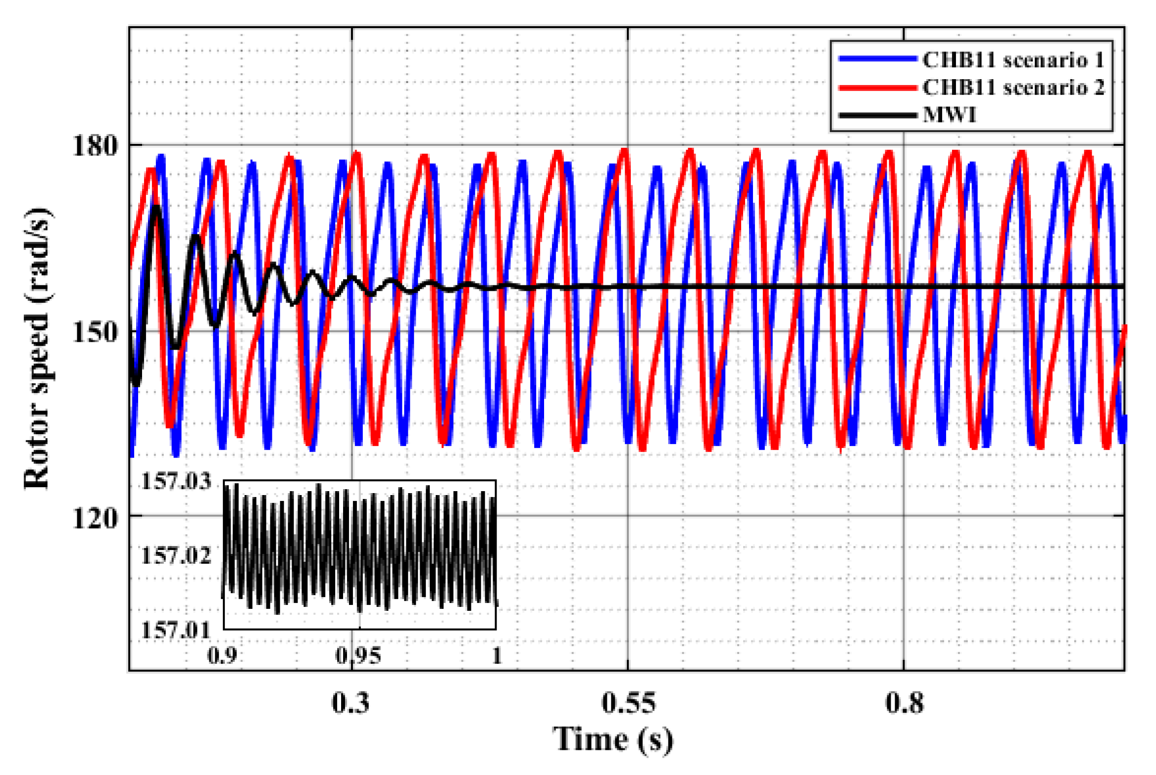
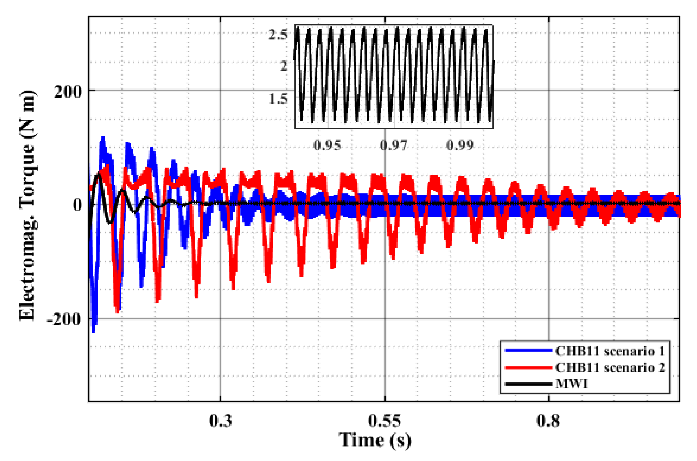
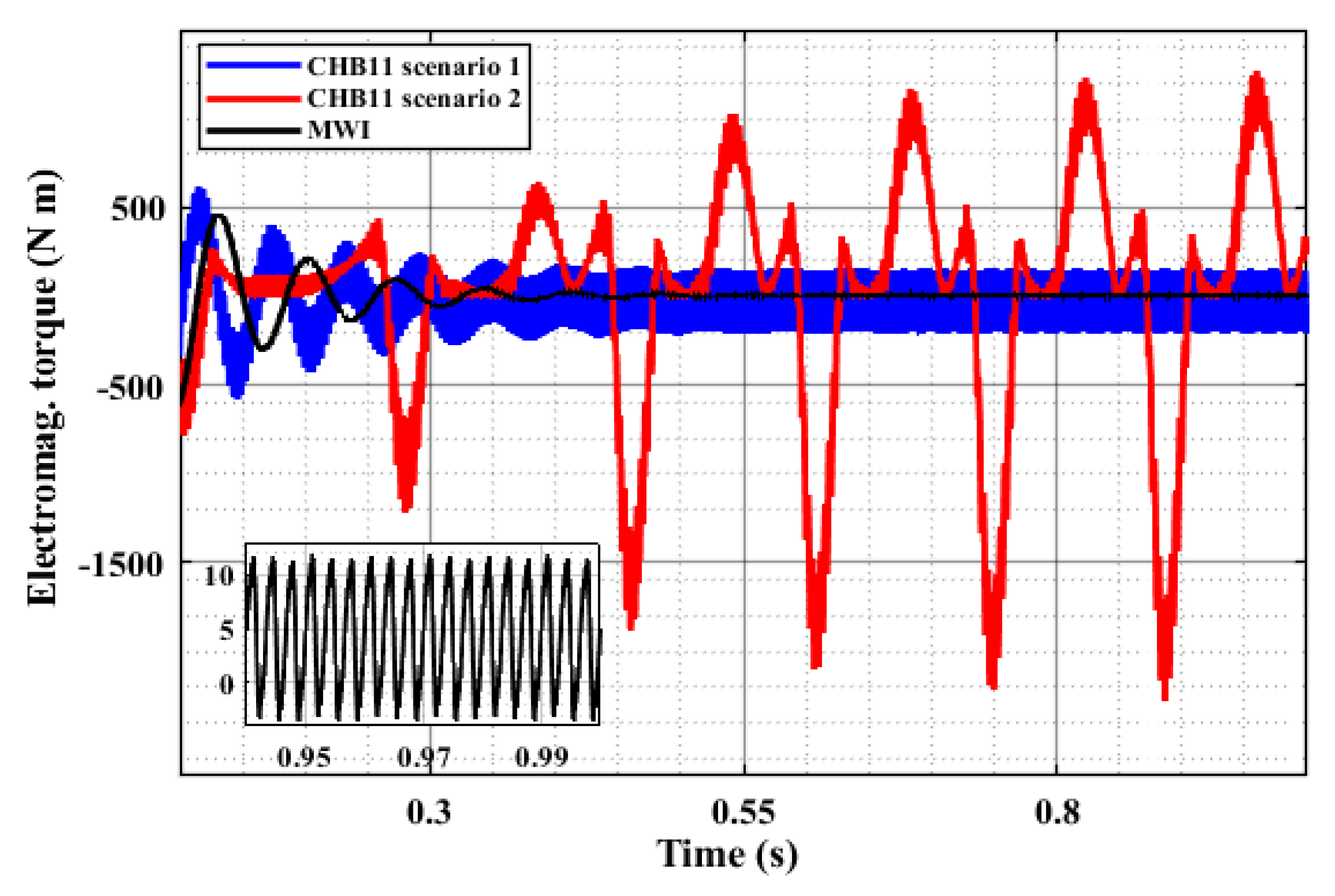
Figure 6 depicts the results of the second case for motor 1 in terms of rotor speed profiles under different stator voltage inputs. The impact on its electromagnetic torques for the first case is presented via Figure 7. Figure 8 shows the rotor speed results for case 9 of parameter variations in motor 2, and Figure 9 portrays its torque profiles for case 1.
Figure 10 and Figure 11 summarize all the selected cases. These figures highlight the impact of the superior voltage quality of the MWI through the minimized ripple content of the rotor speed and electromagnetic torque. Moreover, this summary illustrates that the MWI has the least sensitivity to changes in the parameters. The MWI scenario represents a significant improvement in performance, with lower ripple content and sensitivity than either CHB11 scenario.

4.2. Performance of FCSMPC

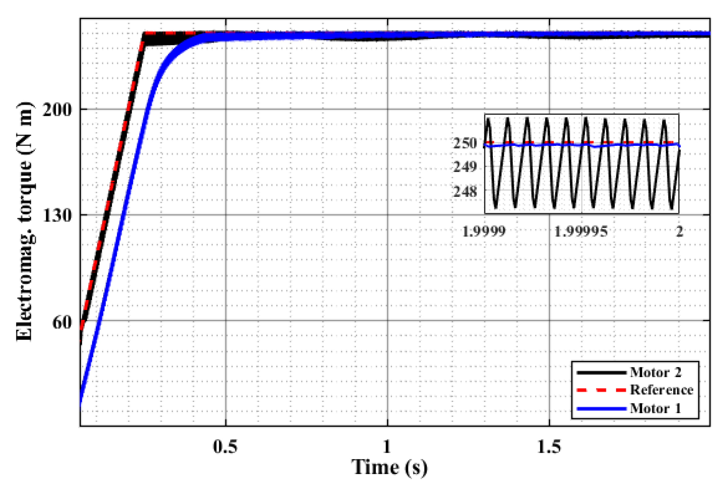
As the superiority of the MWI’s voltage quality has been established in the previous subsection, this portion discusses the performance of FCSMPC in achieving the required electromagnetic torque for MWI-fed motors. Multiple test load torque patterns are included in this study for validation. The first reference pattern (pattern 1) is a fixed step load, while the second one (pattern 2) is a combination of increasing and decreasing ramped loads. The literature contains speed and movement profiles [76,77], and the third, fourth and fifth driving patterns in the present study have been generated to replicate those trends (not exact values). The results provided by FCSMPC are recorded and presented in descriptive, graphical, and tabular formats below.
Figure 12 illustrates the resulting torque of motor 1 under a stepped load torque of 4 N·m. A torque ripple of 0.4 N·m is achieved, which is significantly smaller than the ripple of 1.4 N·m reported in [72] for the same load condition. Figure 13 depicts the obtained curves for the second pattern. The zoomed version of the figure displays a minimum ripple content of about 0.08% for motor 1 and about 1.4% for motor 2 at maximum load.
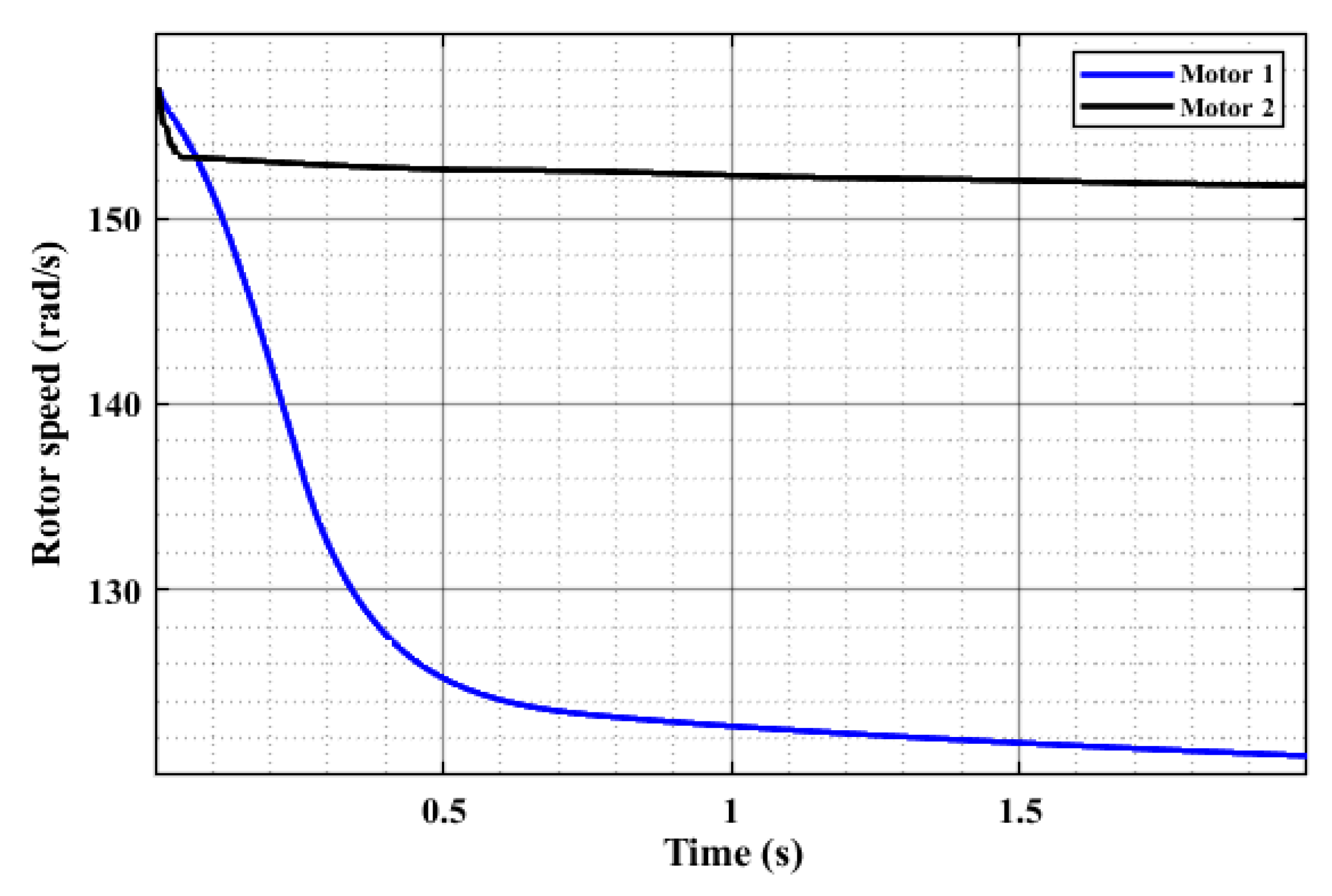
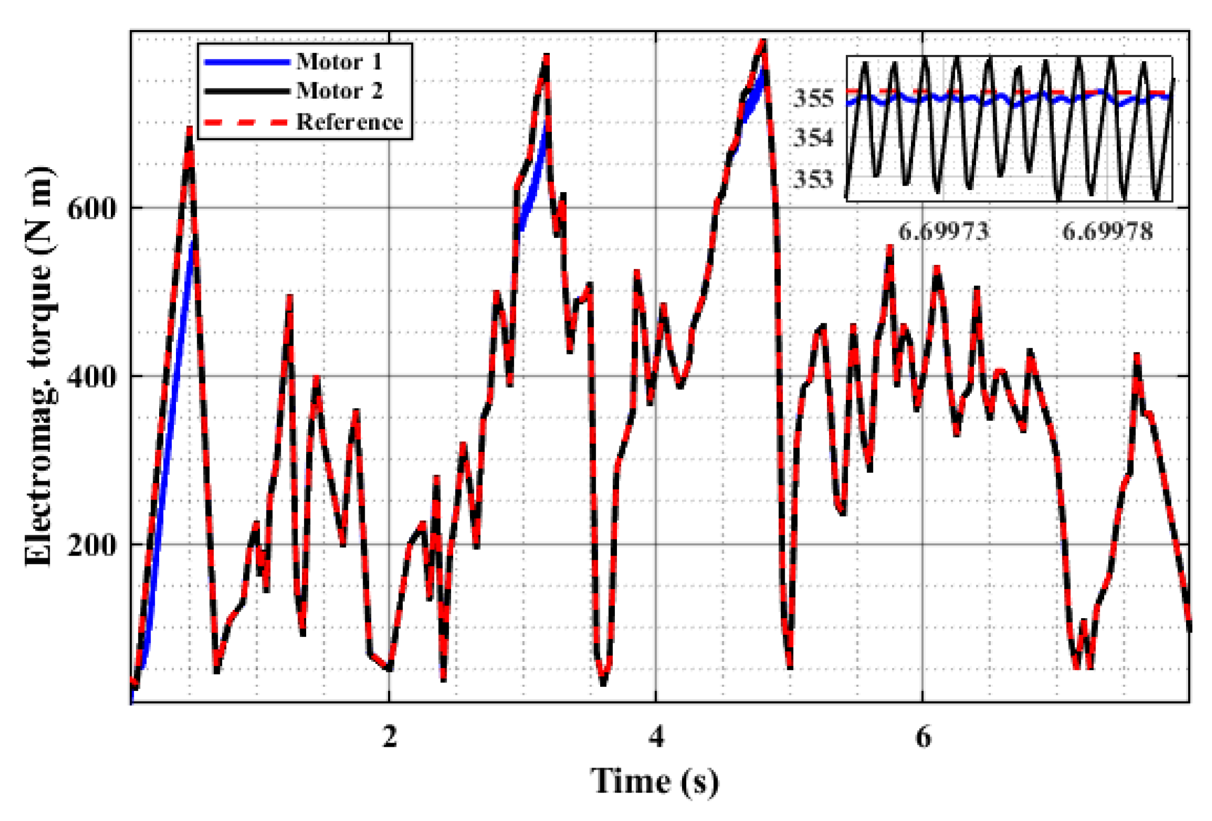
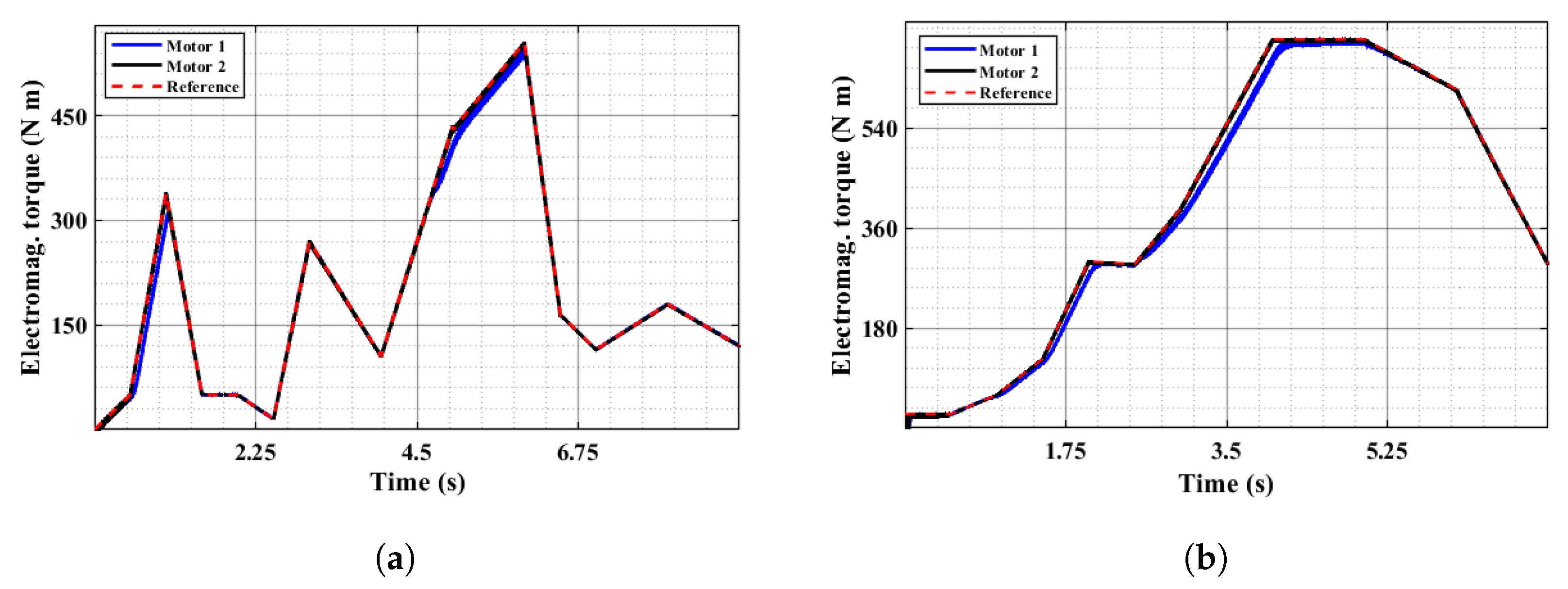
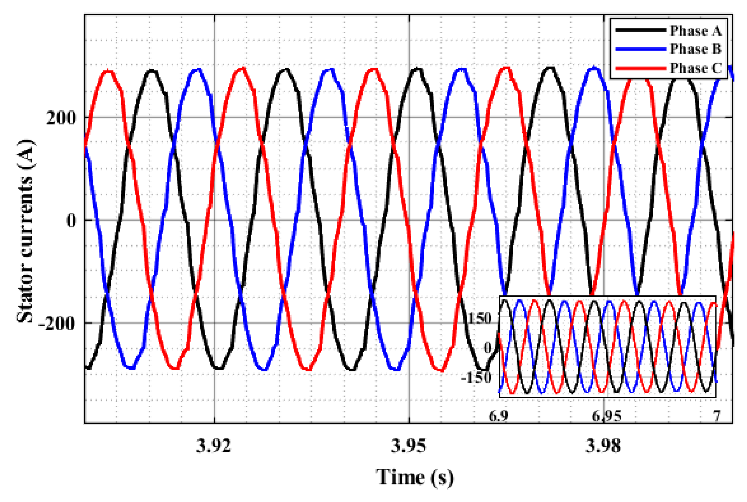
Figure 14 portrays the rotor speed curves for both motors when the ramp-based load is applied where a ripple content below 0.01% is recorded. Figure 15 and Figure 16 show the torque profiles provided by FCSMPC against the driving torque patterns, shown as dotted curves, and the ripple content at the maximum torque points listed in Table 1. It can be seen that the FCSMPC-based MWI-fed IM achieved improved performance, with reduced ripples and smooth torque. Figure 17 depicts the three-phase stator currents for motor 2 with the fifth test profile. For all the discussed driving patterns, the quality of stator currents is listed in Table 2 in terms of THD percentages for one cycle.

5. Conclusions

Torque ripples and vibrations cause faulty motor operation, leading to vehicle and equipment malfunction, financial loss, deterioration of transport-related civil works, and passenger discomfort. The main aim of this study is to minimize torque ripples for induction motors while meeting the torque requirements for driving. To achieve the objective, FCSMPC is applied to MWI-fed IMs, and its performance is validated for low- and high-power motors. Reduced torque ripple values of less than 1% are achieved in different testing scenarios, indicating the impressive performance of FCSMPC with the stator voltage supplied by MWI. The quality of the stator currents is also examined through THD analysis for different load torques. In addition, MWI shows the least sensitivity to simultaneous variations in multiple motor parameters among the tested inverters, with the smallest ripples in rotor speed and electromagnetic torque for all cases. In the future, the fault tolerance scenarios of MWI for electric vehicles can be discussed.

Author Contributions

Conceptualization, S.A.R.K. and M.A.T.; methodology, M.A.T. and S.A.R.K.; software, M.A.T.; validation, S.A.R.K., A.R. and A.A.; formal analysis, M.A.T. and S.A.R.K.; investigation, M.A.T. and S.A.R.K.; resources, S.A.R.K., A.R. and A.A.; data curation, M.A.T. and S.A.R.K.; writing—original draft preparation, M.A.T.; writing—review and editing, S.A.R.K., A.R. and A.A.; visualization, S.A.R.K. and A.R.; supervision, S.A.R.K. and A.R.; project administration, S.A.R.K. All authors have read and agreed to the published version of the manuscript.

Funding

This research received no external funding.

Data Availability Statement

No new data were created or analyzed in this study. Data sharing is not applicable to this article.

Acknowledgments

The authors would also like to acknowledge the Power Systems Simulation Research Lab at the University of Engineering and Technology, Lahore. The computational resources of the laboratory were used in this research.

Conflicts of Interest

The authors declare no conflicts of interest.

Abbreviations and Symbols

The following abbreviations and symbols are used in this manuscript:
FCSMPCFinite Control Set Model Predictive Control
MWIModified W-type Inverter
IMInduction Motor
EVElectric Vehicle
DCMDC Motor
SRMSwitched Reluctance Motor
PMPermanent Magnet
BLDCBrushless DC
PMSMPermanent-Magnet Synchronous Motor
IPMSMInterior-Permanent-Magnetic Synchronous Motor
SynRMSynchronous Reluctance Motor
MPCModel Predictive Control
MLIMultilevel Inverter
CHBCascaded H-Bridge
PIDCProportional–Integral–Derivative Control
VFCVoltage–Frequency Control
PQCPower Quality Control
SHESelective Harmonic Elimination
MPPTMaximum Power Point Tracking
VOCVoltage-Oriented Control
DTCDirect Torque Control
HCH-Infinity Control
SMCSliding Mode Control
DCCDirect Current Control
PCCPredictive Current Control
CHB11Eleven-Level CHB Inverter
THDTotal Harmonic Distortion
T e * Reference Electromagnetic Torque
T e p Predicted Electromagnetic Torque
kCurrent Time Instant
k + 1 Next Time Instant
ϕ s ^ Estimated Stator Flux Vector
ϕ r ^ Estimated Rotor Flux Vector
i s Measured Stator Current Vector
i s p Predicted Stator Current Vector
T e ^ Estimated Electromagnetic Torque
ϕ s p Predicted Stator Flux Vector
v s Stator Voltage Vector
T e p Predicted Electromagnetic Torque
L s Stator Inductance
L r Rotor Inductance
L m Mutual Inductance
R s Stator Resistance
R r Rotor Resistance
σ Leakage Factor
pNumber of Pole Pairs
ω e Rotor Electrical Speed
T s Sample Time
m p            Motor Parameter Constant

Appendix A

Table A1. Default parameters of motor 1.
ParameterValueParameterValue
Nominal RMS voltage460 VNominal power18.45 kVA
Stator resistance0.5968 Ω Stator inductance0.3495 mH
Rotor resistance0.6258 Ω Rotor inductance5.473 mH
Mutual inductance0.0354 HInertia0.05 kg m2 (0.5 for Table 1)
Friction factor0.005879 NmsNumber of pole pairs2
Table A2. Default parameters of motor 2.
ParameterValueParameterValue
Nominal RMS voltage460 VNominal power120 kVA
Stator resistance0.0302 Ω Stator inductance0.283 mH
Rotor resistance0.01721 Ω Rotor inductance0.283 mH
Mutual inductance0.01095 HInertia2 kg m2
Friction factor0.02154 NmsNumber of pole pairs2
T s = 1 μ s, frequency (f) = 50 Hz, and c = 1.5 .

References

  1. Madichetty, S.; Sukumar, M.; Basu, M. New trends in electric motors and selection for electric vehicle propulsion systems. IET Electr. Syst. Transp. 2021, 11, 186–199. [Google Scholar] [CrossRef]
  2. Itu, C.; Sorin, V. The effect of vibrations from racing cars on the human body in formula student races. Appl. Sci. 2023, 13, 12150. [Google Scholar] [CrossRef]
  3. Jedryczka, C.; Danielczyk, D.; Szelag, W. Torque ripple minimization of the permanent magnet synchronous machine by modulation of the phase currents. Sensors 2020, 20, 2406. [Google Scholar] [CrossRef]
  4. Hazar-Yavuz, A.N.; Yavuz, A. Investigation of vehicle-induced whole-body vibration with experimental rat models. J. Res. Pharm. 2023, 27, 2310–2329. [Google Scholar] [CrossRef]
  5. Yang, J.; Leng, J.; Zhou, J.; Chen, R.; Yu, K.; Jiang, Z.; Zou, Y.; Zhang, Z.; Du, J. Study on the impact of vehicle-induced vibration on the flexural behavior of UHPC joints in widened bridges. Urban Lifeline 2024, 2, 20. [Google Scholar] [CrossRef]
  6. Huang, C.-L.; Lee, F.-C.; Liu, C.-J.; Chen, J.-Y.; Lin, J.-Y.; Yang, S.-C. Torque ripple reduction for BLDC permanent magnet motor drive using DC-link voltage and current modulation. IEEE Access 2022, 10, 51272–51284. [Google Scholar] [CrossRef]
  7. Prabhu, N.; Thirumalaivasan, R.; Ashok, B. Critical review on torque ripple sources and mitigation control strategies of BLDC motors in electric vehicle Applications. IEEE Access 2023, 11, 115699–115739. [Google Scholar] [CrossRef]
  8. Yan, L.; Liao, Y.; Lin, H.; Sun, J. Torque ripple suppression of permanent magnet synchronous machines by minimal harmonic current injection. IET Power Electron. 2019, 12, 1368–1375. [Google Scholar] [CrossRef]
  9. Abdel-Aziz, A.; Elgenedy, M.; Williams, B. Review of switched reluctance motor converters and torque ripple minimisation techniques for electric vehicle applications. Energies 2024, 17, 3263. [Google Scholar] [CrossRef]
  10. Oloo, J.; Laszlo, S. Torque ripple minimization for switched reluctance motor drives based on harris hawks–radial basis function approximation. Energies 2025, 18, 1006. [Google Scholar] [CrossRef]
  11. Al Quraan, L.; Szamel, L. Torque ripple reduction of switched reluctance motor using direct instantaneous torque control and adaptive turn-on technique for electric vehicle applications. IET Electr. Power Appl. 2023, 17, 1502–1514. [Google Scholar] [CrossRef]
  12. Jang, H.; Kim, H.; Liu, H.-C.; Lee, H.-J.; Lee, J. Investigation on the torque ripple reduction method of a hybrid electric vehicle motor. Energies 2021, 14, 1413. [Google Scholar] [CrossRef]
  13. Abou-ElSoud, A.M.; Nada, A.S.A.; Abdel-Aziz, A.-A.M.; Sabry, W. Torque ripples reduction of electric vehicle synchronous reluctance motor drive using the strong action controller. Ain Shams Eng. J. 2024, 15, 102428. [Google Scholar] [CrossRef]
  14. Yoon, H.-J.; Castano, A.F.; Voulgaris, P. Adaptive control to suppress torque ripple in electric vehicles. In Proceedings of the IFAC-PapersOnLine 3rd Modeling, Estimation and Control Conference MECC 2023, Lake Tahoe, CA, USA, 2–5 October 2023; Volume 56, pp. 223–228. [Google Scholar] [CrossRef]
  15. Kumar, S.; Pal, Y. Asymmetric multilevel inverter induction motor drive for fuel cell based electrical vehicles. In Proceedings of the 2019 International Conference on Communication and Electronics Systems (ICCES), Coimbatore, India, 17–19 July 2019; pp. 791–795. [Google Scholar] [CrossRef]
  16. Nayak, M.R.; Saritha, M.; Mujeer, S.A.; Devulal, B.; Kumar, T.S. A photovoltaic based multilevel inverter fed induction motor drive. Turcomat 2021, 12, 6196–6212. [Google Scholar] [CrossRef]
  17. Omer, P.; Kumar, J.; Surjan, B.S. A review on reduced switch count multilevel inverter topologies. IEEE Access 2020, 8, 22281–22302. [Google Scholar] [CrossRef]
  18. Salem, M.; Richelli, A.; Yahya, K.; Hamidi, M.N.; Ang, T.-Z.; Alhamrouni, I. A comprehensive review on multilevel inverters for grid-tied system applications. Energies 2022, 15, 6315. [Google Scholar] [CrossRef]
  19. Kadam, A.; Shukla, A. A multilevel transformerless inverter employing ground connection between PV negative terminal and grid neutral point. IEEE Trans. Ind. Electron. 2017, 64, 8897–8907. [Google Scholar] [CrossRef]
  20. Mehta, S.; Puri, V. A review of different multi-level inverter topologies for grid integration of solar photovoltaic system. Renew. Energy Focus 2022, 43, 263–276. [Google Scholar] [CrossRef]
  21. Jain, S.; Sonti, V. A highly efficient and reliable inverter configuration based cascaded multilevel inverter for PV systems. IEEE Trans. Ind. Electron. 2017, 64, 2865–2875. [Google Scholar] [CrossRef]
  22. Barzegarkhoo, R.; Forouzesh, M.; Lee, S.S.; Blaabjerg, F.; Siwakoti, Y.P. Switched-capacitor multilevel inverters: A comprehensive review. IEEE Trans. Power Electron. 2022, 37, 11209–11243. [Google Scholar] [CrossRef]
  23. Lee, S.S. Single-stage switched-capacitor module (S3CM) topology for cascaded multilevel inverter. IEEE Trans. Power Electron. 2018, 33, 8204–8207. [Google Scholar] [CrossRef]
  24. Hassan, A.; Yang, X.; Chen, W. A multi-cell 21-level hybrid multilevel inverter synthesizes a reduced number of components with voltage boosting property. IEEE Access 2020, 8, 224439–224451. [Google Scholar] [CrossRef]
  25. Siddique, M.D.; Iqbal, A.; Memon, M.A.; Mekhilef, S. A new configurable topology for multilevel inverter with reduced switching components. IEEE Access 2020, 8, 188726–188741. [Google Scholar] [CrossRef]
  26. Taghvaie, A.; Jafar, A.; Rezanejad, M. A self-balanced step-up multilevel inverter based on switched-capacitor structure. IEEE Trans. Power Electron. 2018, 33, 199–209. [Google Scholar] [CrossRef]
  27. Siddique, M.D.; Mekhilef, S.; Rawa, M.; Wahyudie, A.; Chokaev, B.; Salamov, I. Extended multilevel inverter topology with reduced switch count and voltage stress. IEEE Access 2020, 8, 201835–201846. [Google Scholar] [CrossRef]
  28. Mondol, M.H.; Tür, M.R.; Biswas, S.P.; Hosain, M.K.; Shuvo, S.; Hossain, E. Compact three phase multilevel inverter for low and medium power photovoltaic systems. IEEE Access 2020, 8, 60824–60837. [Google Scholar] [CrossRef]
  29. Abarzadeh, M.; Al-Haddad, K. Generalized circuit topology of Qn-hybrid-NPC multilevel converter with novel decomposed sensor-less modulation method. IEEE Access 2019, 7, 59813–59824. [Google Scholar] [CrossRef]
  30. Ahmed, S.; Saqib, M.A.; Kashif, S.A.R.; Hashmi, K.; Aymen, F.; AboRas, K.M.; Jasińska, L.; Leonowicz, Z. A modified multi-level inverter system for grid-tied DES applications. Sustainability 2022, 14, 16545. [Google Scholar] [CrossRef]
  31. Saeedian, M.; Adabi, J.; Hosseini, S.M. Cascaded multilevel inverter based on symmetric–asymmetric DC sources with reduced number of components. IET Power Electron. 2017, 10, 1468–1478. [Google Scholar] [CrossRef]
  32. Agrawal, R.; Jain, S. Multilevel inverter for interfacing renewable energy sources with low/medium- and high-voltage grids. IET Renew. Power Gener. 2017, 11, 1822–1831. [Google Scholar] [CrossRef]
  33. Bughneda, A.; Salem, M.; Richelli, A.; Ishak, D.; Alatai, S. Review of multilevel inverters for PV energy system applications. Energies 2021, 14, 1585. [Google Scholar] [CrossRef]
  34. Poorfakhraei, A.; Narimani, M.; Emadi, A. A review of modulation and control techniques for multilevel inverters in traction applications. IEEE Access 2021, 9, 24187–24204. [Google Scholar] [CrossRef]
  35. Ahmed, S.; Saqib, M.A.; Kashif, S.A.R. Modified W-type configuration for a single-phase reduced parts count 81-level inverter. PLoS ONE 2022, 17, e0269714. [Google Scholar] [CrossRef]
  36. Sedhom, B.E.; El-Saadawi, M.M.; Hatata, A.Y.; Abd-Raboh, E.-H.E. H-Infinity versus model predictive control methods for seamless transition between islanded- and grid-connected modes of microgrids. IET Renew. Power Gener. 2020, 14, 856–870. [Google Scholar] [CrossRef]
  37. Sarwar, M.I.; Sarwar, A.; Farooqui, S.A.; Tariq, M.; Fahad, M.; Beig, A.R. A hybrid nearest level combined with PWM control strategy: Analysis and implementation on cascaded H-bridge multilevel inverter and its fault tolerant topology. IEEE Access 2021, 9, 44266–44282. [Google Scholar] [CrossRef]
  38. Ko, Y.; Tcai, A.; Liserre, M. DC-link voltage balancing modulation for cascaded H-bridge converters. IEEE Access 2021, 9, 103524–103532. [Google Scholar] [CrossRef]
  39. Jamma, M.; Barara, M.; Akherraz, M.; Enache, B.A. Voltage oriented control of three-phase PWM rectifier using space vector modulation and input output feedback linearization theory. In Proceedings of the 2016 8th International Conference on Electronics, Computers and Artificial Intelligence (ECAI), Ploiesti, Romania, 30 June–2 July 2016; pp. 1–8. [Google Scholar] [CrossRef]
  40. Dyanamina, G.; Kakodia, S.K. Adaptive neuro fuzzy inference system based decoupled control for neutral point clamped multi level inverter fed induction motor drive. Chin. J. Electr. Eng. 2021, 7, 70–82. [Google Scholar] [CrossRef]
  41. Fatima, A.; Almas, T.; Biabani, M.A.K.A.; Imran, M. Sliding mode control of induction motor used in traction. In Proceedings of the 2016 International Conference on Electrical, Electronics, and Optimization Techniques (ICEEOT), Chennai, India, 3–5 March 2016; pp. 3336–3343. [Google Scholar] [CrossRef]
  42. Dekka, A.; Wu, B.; Yaramasu, V.; Fuentes, R.L.; Zargari, N.R. Model predictive control of high-power modular multilevel converters—An overview. IEEE J. Emerg. Sel. Top. Power Electron. 2019, 7, 168–183. [Google Scholar] [CrossRef]
  43. Ghauri, M.A.; Abbasi, M.A.; Shahid, M.B.; Noman, M.; Hakeem, M.A. Finite control set model predictive field-oriented control for three-phase induction motor drives. J. Eng. Res. 2022. [Google Scholar] [CrossRef]
  44. Zhang, Y.; Yang, H.; Xia, B. Model-predictive control of induction motor drives: Torque control versus flux control. IEEE Trans. Ind. Appl. 2016, 52, 4050–4060. [Google Scholar] [CrossRef]
  45. Harbi, I.; Rodriguez, J.; Liegmann, E.; Makhamreh, H.; Heldwein, M.L.; Novak, M. Model-predictive control of multilevel inverters: Challenges, recent advances, and trends. IEEE Trans. Power Electron. 2023, 38, 10845–10868. [Google Scholar] [CrossRef]
  46. Zhang, Y.; Bai, Y.; Yang, H. A universal multiple vector-based model predictive control of induction motor drives. IEEE Trans. Power Electron. 2018, 33, 6957–6969. [Google Scholar] [CrossRef]
  47. Mohapatra, S.R.; Agarwal, V. Model predictive controller with reduced complexity for grid-tied multilevel inverters. IEEE Trans. Ind. Electron. 2019, 66, 8851–8855. [Google Scholar] [CrossRef]
  48. Baig, M.A.; Kashif, S.A.R.; Khan, I.A.; Abbas, G. Quick search algorithm-based direct model predictive control of grid-connected 289-level multilevel inverter. Electronics 2023, 12, 3312. [Google Scholar] [CrossRef]
  49. Alkhaldi, A.; Elkhateb, A.; Laverty, D. Voltage lifting techniques for non-isolated DC/DC converters. Electronics 2023, 12, 718. [Google Scholar] [CrossRef]
  50. Zerdali, E.; Rivera, M.; Wheeler, P. A review on weighting factor design of finite control set model predictive control strategies for AC electric drives. IEEE Trans. Power Electron. 2024, 39, 9967–9981. [Google Scholar] [CrossRef]
  51. Penthala, T.; Kaliaperumal, S. Predictive control of induction motors using cascaded artificial neural network. Electr. Eng. 2024, 106, 2985–3000. [Google Scholar] [CrossRef]
  52. Kasri, A.; Ouari, K.; Belkhier, Y.; Bajaj, M.; Zaitsev, I. Optimizing electric vehicle powertrains peak performance with robust predictive direct torque control of induction motors: A practical approach and experimental validation. Sci. Rep. 2024, 14, 14977. [Google Scholar] [CrossRef]
  53. Fang, X.; Lin, S.; Wang, X.; Yang, Z.; Lin, F.; Tian, Z. Model predictive current control of traction permanent magnet synchronous motors in six-step operation for railway application. IEEE Trans. Ind. Electron. 2022, 69, 8751–8759. [Google Scholar] [CrossRef]
  54. Kousalya, V.; Rai, R.; Singh, B. Sliding model-based predictive torque control of induction motor for electric vehicle. IEEE Trans. Ind. Appl. 2022, 58, 742–752. [Google Scholar] [CrossRef]
  55. Rodriguez, J.; Garcia, C.; Mora, A.; Davari, S.A.; Rodas, J.; Valencia, D.F. Latest advances of model predictive control in electrical drives—part II: Applications and benchmarking with classical control methods. IEEE Trans. Power Electron. 2022, 37, 5047–5061. [Google Scholar] [CrossRef]
  56. Usha, S.; Geetha, P.; Geetha, A.; Palanisamy, R.; Thentral, T.M.T.; Mahato, B.; Giri, N.C.; Alharbi, M. Performance enhancement of sensorless induction motor drive using modified direct torque control techniques for traction application. Alex. Eng. J. 2024, 108, 518–538. [Google Scholar] [CrossRef]
  57. Kim, D.-K.; Kim, D.-M.; Park, J.-C.; Lee, S.-G.; Yoo, J.; Lim, M.-S. Torque ripple reduction of BLDC traction motor of electric wheelchair for ride comfort improvement. J. Electr. Eng. Technol. 2022, 17, 351–360. [Google Scholar] [CrossRef]
  58. Zhao, W.; Lu, B.; Liu, Z.; Zhang, G. An improved passivity-based control for suppressing the traction motor torque ripples due to traction network voltage fluctuation in high-speed railways. IET Power Electron. 2023, 16, 2287–2300. [Google Scholar] [CrossRef]
  59. Holczer, A.; Freijedo, F.D.; Bojoi, R. Optimal high-frequency injection minimizing high-frequency torque ripple for sensorless control of electric vehicle IPM traction motors. IEEE Trans. Ind. Electron. 2025, 72, 4424–4435. [Google Scholar] [CrossRef]
  60. Yue, H.; He, H.; Han, M. Study on torsional vibration characteristics and suppression of electric vehicles with dualmotor drive system. J. Frankl. Inst. 2023, 360, 380–402. [Google Scholar] [CrossRef]
  61. Liu, W.; He, H.; Sun, F.; Wang, H. Optimal design of adaptive shaking vibration control for electric vehicles. Veh. Syst. Dyn. 2019, 57, 134–159. [Google Scholar] [CrossRef]
  62. Rezig, A.; Boudendouna, W.; Djerdir, A.; N’Diaye, A. Investigation of optimal control for vibration and noise reduction in-wheel switched reluctance motor used in electric vehicle. Math. Comput. Simul. 2020, 167, 267–280. [Google Scholar] [CrossRef]
  63. Zhao, Z.; Taghavifar, H.; Du, H.; Qin, Y.; Dong, M.; Gu, L. In-wheel motor vibration control for distributed-driven electric vehicles: A review. IEEE Trans. Transp. Electrif. 2021, 7, 2864–2880. [Google Scholar] [CrossRef]
  64. M, D.; Samithas, D.; Balachandran, P.; Selvarajan, S. Experimental analysis of enhanced finite set model predictive control and direct torque control in SRM drives for torque ripple reduction. Sci. Rep. 2024, 14, 16805. [Google Scholar] [CrossRef]
  65. Varvolik, V.; Buticchi, G.; Prystupa, D.; Wang, S.; Aboelhassan, A.; Peresada, S. Comparative study on torque ripple reduction considering minimum losses for synchronous reluctance motor drives. IEEE Trans. Transp. Electrif. 2024, 10, 6527–6538. [Google Scholar] [CrossRef]
  66. Wu, L.; Lyu, Z. Harmonic injection-based torque ripple reduction of PMSM With improved DC-link voltage utilization. IEEE Trans. Power Electron. 2023, 38, 7976–7981. [Google Scholar] [CrossRef]
  67. Rafaq, M.S.; Midgley, W.; Steffen, T. A review of the state of the art of torque ripple minimization techniques for permanent magnet synchronous motors. IEEE Trans. Ind. Inform. 2024, 20, 1019–1031. [Google Scholar] [CrossRef]
  68. Cortes, P.; Wilson, A.; Kouro, S.; Rodriguez, J.; Abu-Rub, H. Model predictive control of cascaded H-bridge multilevel inverters. In Proceedings of the 2009 13th European Conference on Power Electronics and Applications, Barcelona, Spain, 8–10 September 2009; pp. 1–9. [Google Scholar]
  69. Baek, J.-Y.; Lee, K.-B. Model predictive current control strategy for improved dynamic response in cascaded H-bridge multilevel inverters. J. Electr. Eng. Technol. 2024, 19, 1395–1405. [Google Scholar] [CrossRef]
  70. Varga, T.; Benšić, T.; Jerković Štil, V.; Barukčić, M. Continuous control set predictive current control for induction machine. Appl. Sci. 2021, 11, 6230. [Google Scholar] [CrossRef]
  71. Arias-Esquivel, Y.; Cárdenas, R.; Urrutia, M.; Diaz, M.; Tarisciotti, L.; Clare, J.C. Continuous control set model predictive control of a modular multilevel converter for drive applications. IEEE Trans. Ind. Electron. 2023, 70, 8723–8733. [Google Scholar] [CrossRef]
  72. Habibullah, M.; Lu, D.D.-C.; Xiao, D.; Rahman, M.F. A simplified finite-state predictive direct torque control for induction motor drive. IEEE Trans. Ind. Electron. 2016, 63, 3964–3975. [Google Scholar] [CrossRef]
  73. Rodriguez, J.; Cortes, P. Predictive Control of Power Converters and Electrical Drives; Wiley: Santiago, Chile, 2012. [Google Scholar]
  74. Tariq, M.A.; Kashif, S.A.R. Impact of the voltage profiles of CHB vs. MW-type inverters on torque and speed ripples for 3-phase induction motors. In Proceedings of the 2024 IEEE Workshop on Control and Modeling for Power Electronics (COMPEL), Lahore, Pakistan, 24–27 June 2024; pp. 1–7. [Google Scholar] [CrossRef]
  75. Tariq, M.A.; Shami, U.T.; Fakhar, M.S.; Kashif, S.A.R.; Abbas, G.; Ullah, N.; Mohammad, A.; Farrag, M.E. Dragonfly algorithm-based optimization for selective harmonics elimination in cascaded H-bridge multilevel inverters with statistical comparison. Energies 2022, 15, 6826. [Google Scholar] [CrossRef]
  76. Schlemmer, E.; Laussegger-Rauch, H. E-drive component tests derived from vehicle master test cases in the SyrNemo collaborative research project. Renew. Energies Power Qual. J. 2016, 14, 166–171. [Google Scholar] [CrossRef]
  77. Wu, M.; Zhang, S.; Dong, Y. A novel model-based driving behavior recognition system using motion sensors. Sensors 2016, 16, 1746. [Google Scholar] [CrossRef]
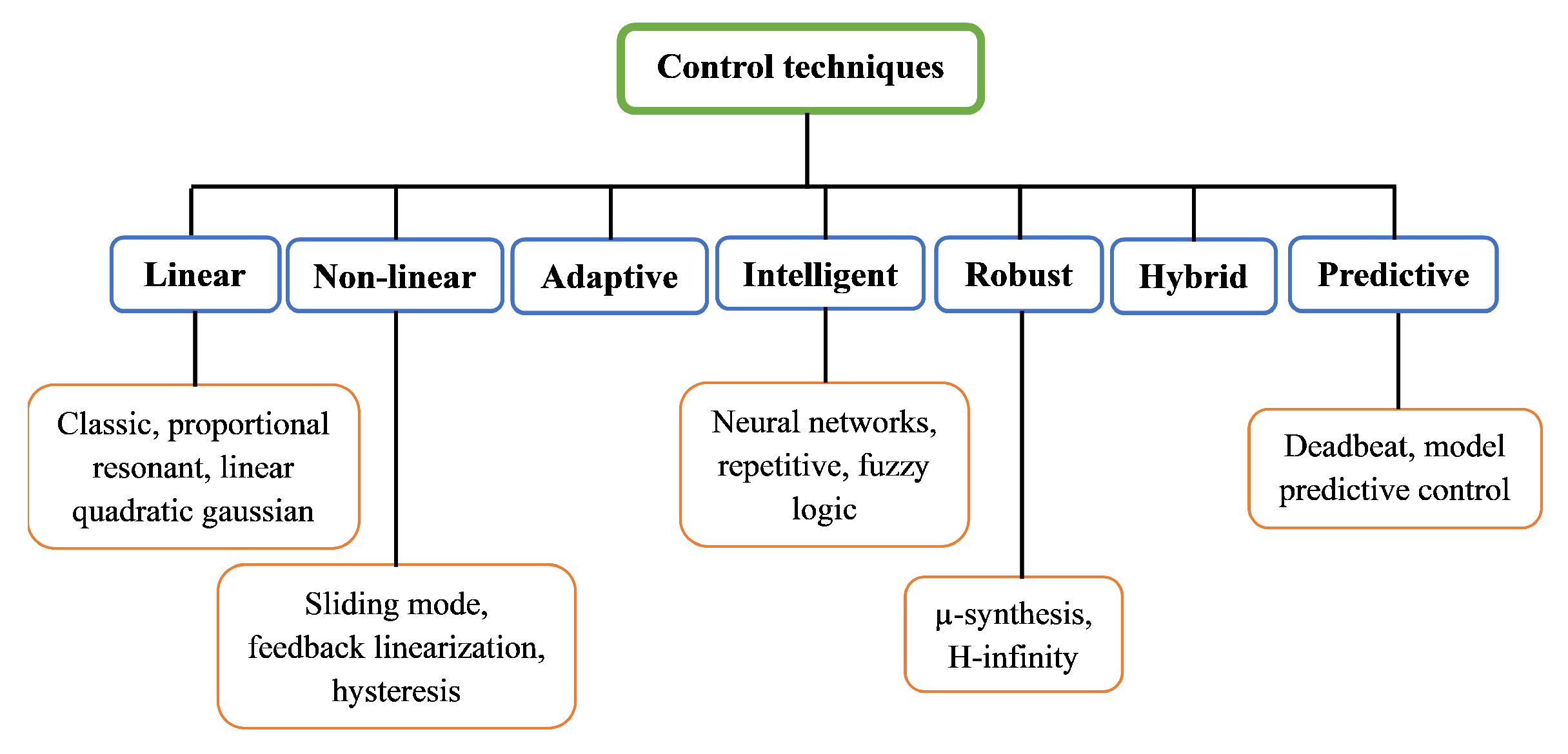
Figure 1. Categorization of control techniques [49].
Wevj 16 00539 g001
Figure 2. Methodology flowchart.
Wevj 16 00539 g002
Figure 3. Setup for FCSMPC.
Wevj 16 00539 g003
Figure 4. MWI (single leg).
Wevj 16 00539 g004
Figure 5. MWI output (3-phase).
Wevj 16 00539 g005
Figure 6. Comparison of rotor speed curves for different voltage profiles (case 2, motor 1).
Wevj 16 00539 g006
Figure 7. Comparison of electromagnetic torque curves for different voltage profiles (case 1, motor 1).
Wevj 16 00539 g007
Figure 8. Comparison of rotor speed curves for different voltage profiles (case 9, motor 2).
Wevj 16 00539 g008
Figure 9. Comparison of electromagnetic torque curves for different voltage profiles (case 1, motor 2).
Wevj 16 00539 g009
Figure 10. Impact of parameter variations on rotor speed for motor 1 (a) and motor 2 (b).
Wevj 16 00539 g010
Figure 11. Impact of parameter variations on electromagnetic torque for motor 1 (a) and motor 2 (b).
Wevj 16 00539 g011
Figure 12. Actual electromagnetic torque (motor 1, pattern 1).
Wevj 16 00539 g012
Figure 13. Reference vs. actual electromagnetic torque (pattern 2).
Wevj 16 00539 g013
Figure 14. Rotor speeds for the two motors (pattern 2).
Wevj 16 00539 g014
Figure 15. Reference vs. actual electromagnetic torque (pattern 3).
Wevj 16 00539 g015
Figure 16. Reference vs. actual electromagnetic torque for pattern 4 (a) and pattern 5 (b).
Wevj 16 00539 g016
Figure 17. Stator phase currents (motor 2, pattern 5).
Wevj 16 00539 g017
Table 1. Magnitude of torque ripples for the two motors.
Driving ProfileMaximum Ripple for Motor 1 at Peak LoadMaximum Ripple for Motor 2 at Peak Load
Pattern 21.72%3.07%
Pattern 31.9%0.63%
Pattern 42.22%0.9%
Pattern 51.87%0.7%
Table 2. THD for stator phase currents.
Driving ProfileTHD
Pattern 23.41%
Pattern 34.64%
Pattern 43.09%
Pattern 53.19%
Disclaimer/Publisher’s Note: The statements, opinions and data contained in all publications are solely those of the individual author(s) and contributor(s) and not of MDPI and/or the editor(s). MDPI and/or the editor(s) disclaim responsibility for any injury to people or property resulting from any ideas, methods, instructions or products referred to in the content.