1. Introduction
Due to the rising geopolitical and environmental concerns surrounding rare-earth permanent magnet supply chains, along with significant price volatility, there has been increasing interest in developing alternative electric machines that do not rely on rare-earth materials [
1,
2,
3]. Among the promising candidates are wound field synchronous machines (WFSMs), synchronous reluctance machines (SynRMs), and induction machines (IMs), which avoid the need for permanent magnets. WFSMs, in particular, offer electronically controllable excitation and high torque potential. However, despite these advantages, non-rare-earth machines still struggle to match the high power density and efficiency of permanent magnet synchronous machines (PMSMs), especially in high-performance applications.
WFSMs generate magnetic flux through field windings placed on the rotor, in contrast to PMSMs, which rely on interior permanent magnets. This allows WFSMs to avoid the cost and supply issues associated with rare-earth materials. Furthermore, the ability to dynamically control the field excitation current enables operational flexibility over a wide speed range and supports advanced control strategies such as field weakening and regenerative braking [
4]. In addition, their salient-pole rotor structure contributes to higher reluctance torque, enhancing the machine’s output capability. However, the introduction of field windings in the rotor leads to increased copper loss, particularly due to the presence of both stator and rotor windings, which can pose challenges for thermal management [
5].
WFSMs typically employ non-grain-oriented electrical steel (NOES) due to its isotropic magnetic properties, which ensure consistent performance regardless of the flux direction. However, recent studies have explored the selective application of grain-oriented electrical steel (GOES) to improve efficiency and reduce core losses in electric machines. GOES exhibits superior magnetic permeability and lower hysteresis loss along its rolling direction, as the crystal grains are aligned during the manufacturing process. Nevertheless, due to its pronounced anisotropy, the magnetic performance of GOES significantly deteriorates when the magnetic flux deviates from the rolling direction, which poses challenges for its application in rotating machines.
GOES is primarily used in stationary equipment such as transformers [
6], where the magnetic flux direction is constant. For rotating machines, it is selectively applied to regions where the flux remains unidirectional, such as stator or rotor teeth [
7,
8,
9,
10,
11]. In prior studies, applying GOES to the stator of a PMSM for HEV applications led to a 5.5% torque increase, a 9.64% reduction in core loss, and a 0.25% efficiency improvement [
12], demonstrating the material’s potential in improving performance when properly aligned.
In this study, the magnetic flux behavior in a WFSM for xEV applications was analyzed to identify regions dominated by alternating versus rotating fields. Based on this classification, GOES was selectively applied to the stator and rotor teeth, where the flux direction remains relatively constant, while NOES was retained in other regions. Four design configurations with different GOES placement strategies were evaluated through FEA to compare back-EMF, torque, and core loss characteristics.
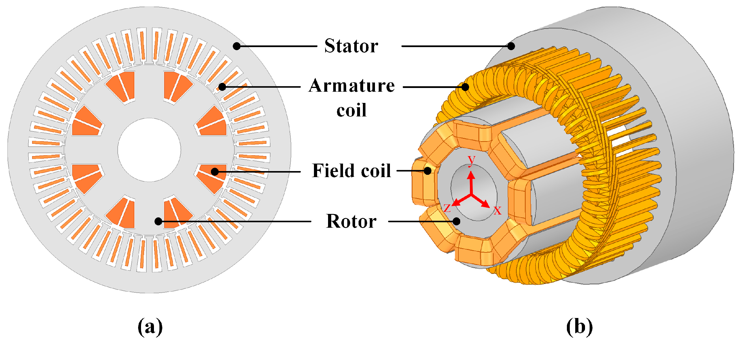
The configuration showing the best performance was then used as the basis for multi-objective design optimization. Using Latin Hypercube Sampling (LHS) for sensitivity analysis, a metamodel was constructed to predict performance trends, followed by a genetic algorithm (GA)-based global search targeting improvements in both power density and efficiency. The structure and electrical specifications of the WFSM are summarized in
Figure 1 and
Table 1.
2. Design Considerations for GOES-NOES Hybrid Cores in WFSMs
2.1. Characteristics of GOES and NOES Materials
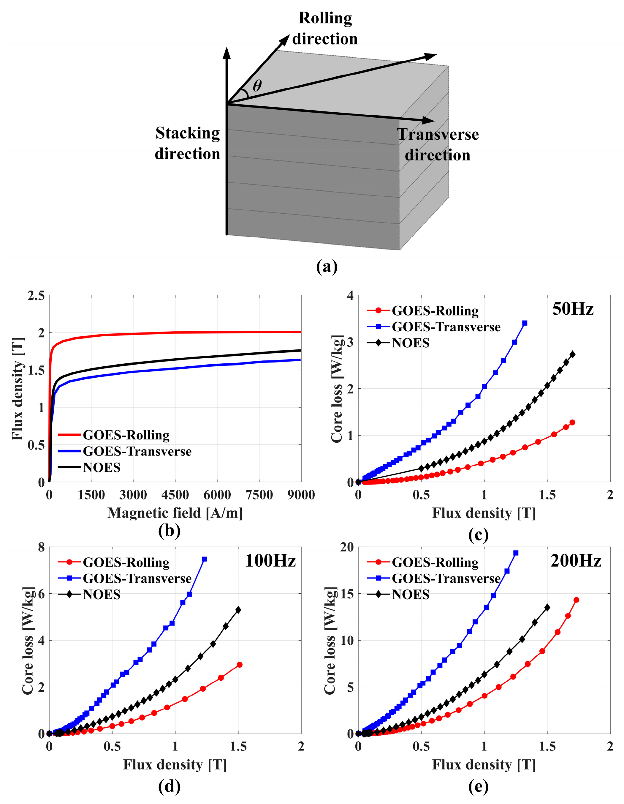
WFSMs commonly adopt NOES due to its isotropic magnetic properties, which enable uniform performance regardless of flux direction—an essential feature for rotating machines. In contrast, GOES is engineered with grain alignment in the rolling direction, resulting in superior magnetic permeability and lower core loss along that axis. However, its performance significantly deteriorates in the transverse direction due to strong anisotropy, as illustrated in
Figure 2a.
Figure 2b–e compare the B–H and B–P characteristics of GOES and NOES at different frequencies. The GOES data represent the ideal case at θ = 0°, aligned with the rolling direction, showing higher flux density and lower core loss. In actual FEM simulations, flux density and losses at arbitrary angles are interpolated between the 0° and 90° B–H curves.
2.2. Alternating and Rotating Field Analysis in the WFSM Cores
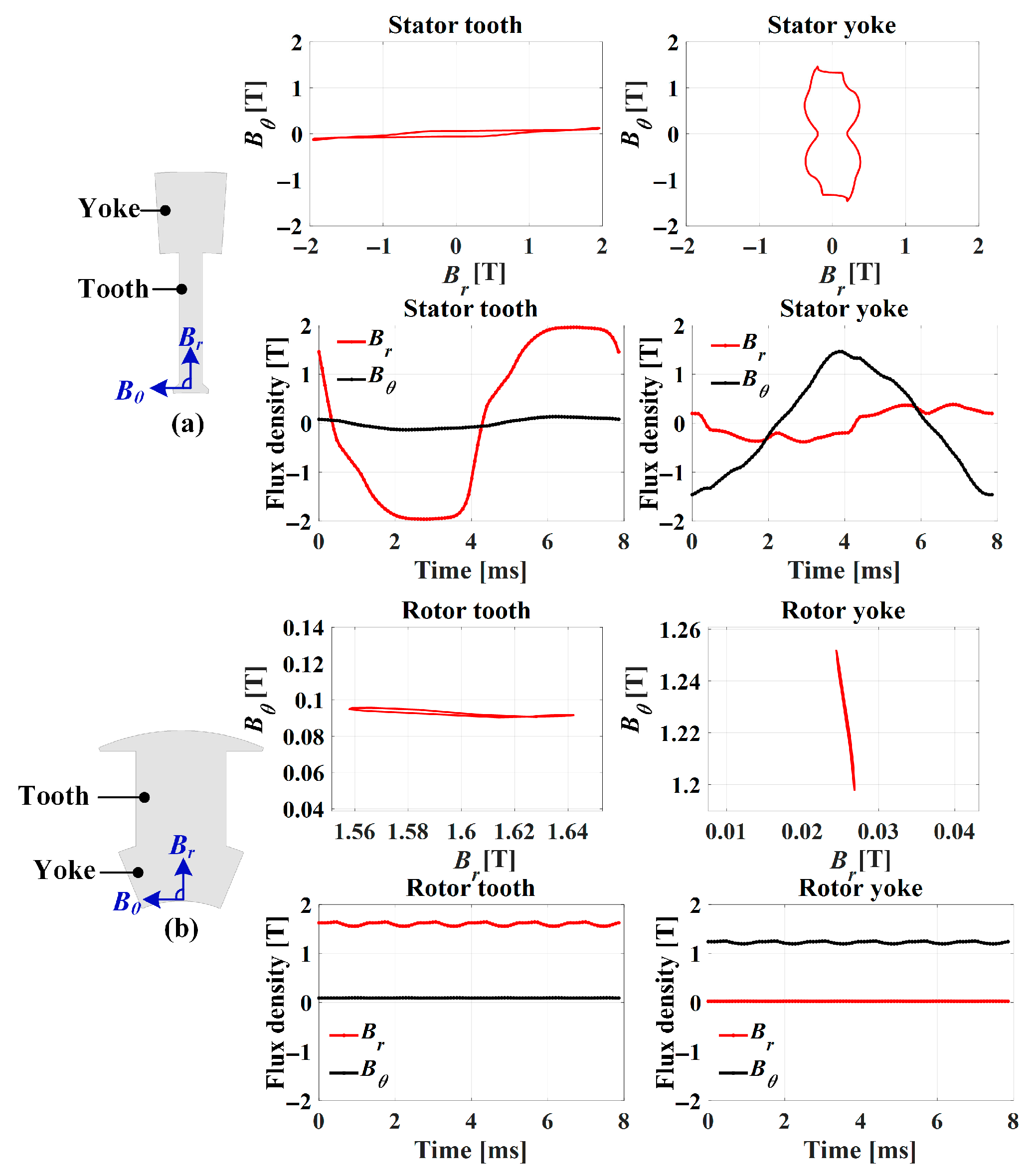
Figure 3 shows the magnetic flux behavior in the stator and rotor regions of the WFSM. In the stator and rotor teeth areas, the radial flux density exhibits significant fluctuation compared to the tangential component, indicating the presence of alternating magnetic fields. In contrast, the stator yoke displays relatively balanced variations in both radial and tangential directions, which characterizes a rotating magnetic field.
Based on this observation, the GOES rolling direction was aligned with regions dominated by alternating fields—specifically, the stator and rotor teeth—to minimize core loss [
13]. In the yoke regions, where multidirectional flux exists, NOES was retained due to its isotropic magnetic behavior.
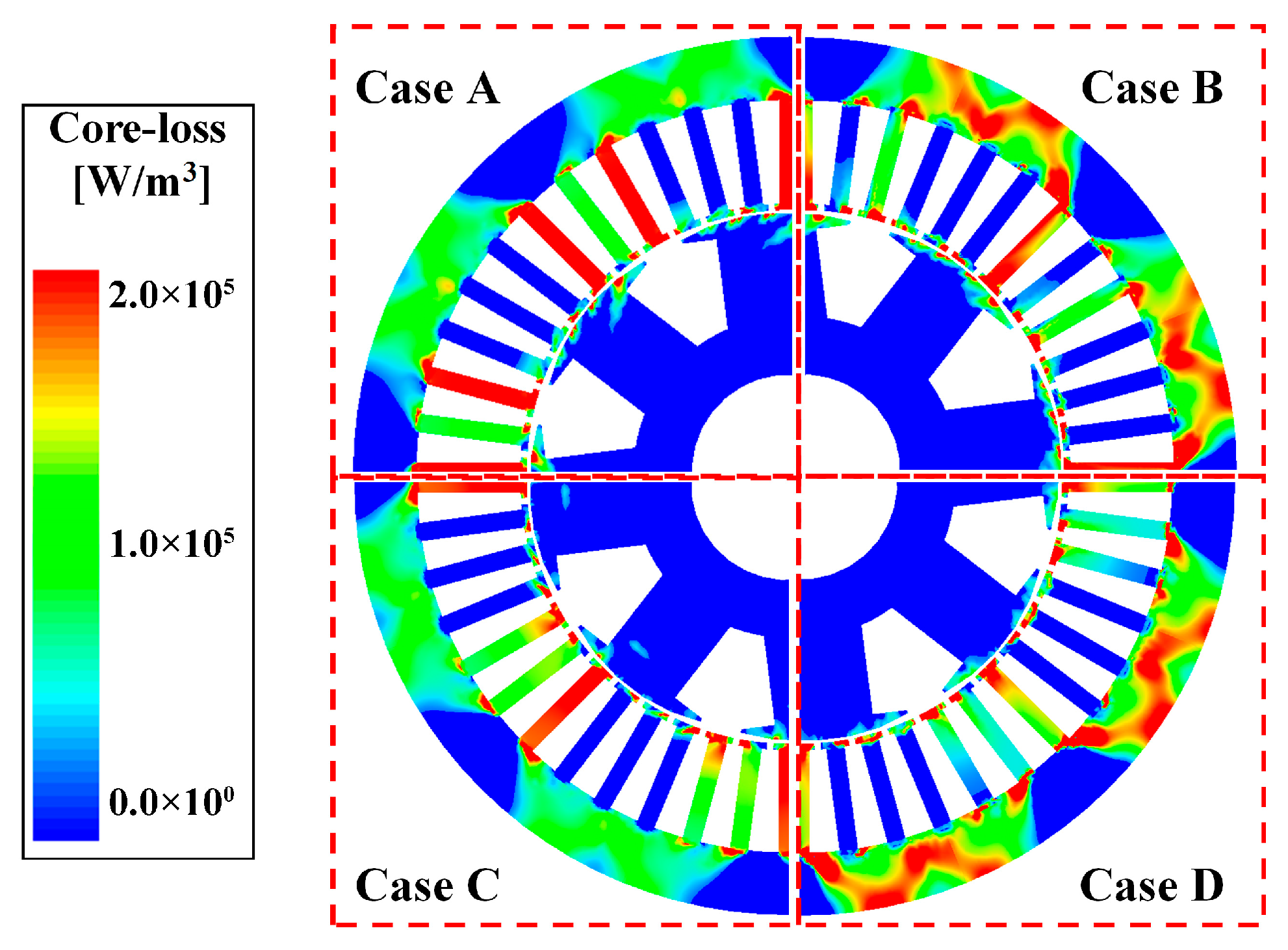
Considering practical manufacturing constraints such as lamination alignment and punching direction, GOES was applied only to the tooth areas. Accordingly, four material configurations were proposed to investigate the performance impact of selective GOES application: Case A (NOES in all regions), Case B (GOES in stator teeth), Case C (GOES in rotor teeth), and Case D (GOES in both stator and rotor teeth). These configurations are detailed in
Figure 4 and evaluated comparatively in
Section 3.
3. Comparison of Electromagnetic Performance of GOES- and NOES-Based WFSMs
3.1. Characteristic Analysis of GOES- and NOES-Based WFSMs Under Load Conditions
Under load conditions, a temperature of 75 °C was applied to reflect thermal effects on material properties. The simulation included current phase angle adjustment according to each operating point and applied field weakening control to the excitation winding. This enabled the model to determine the most efficient operating condition for a given torque by utilizing the controllability of both stator and field currents [
14].
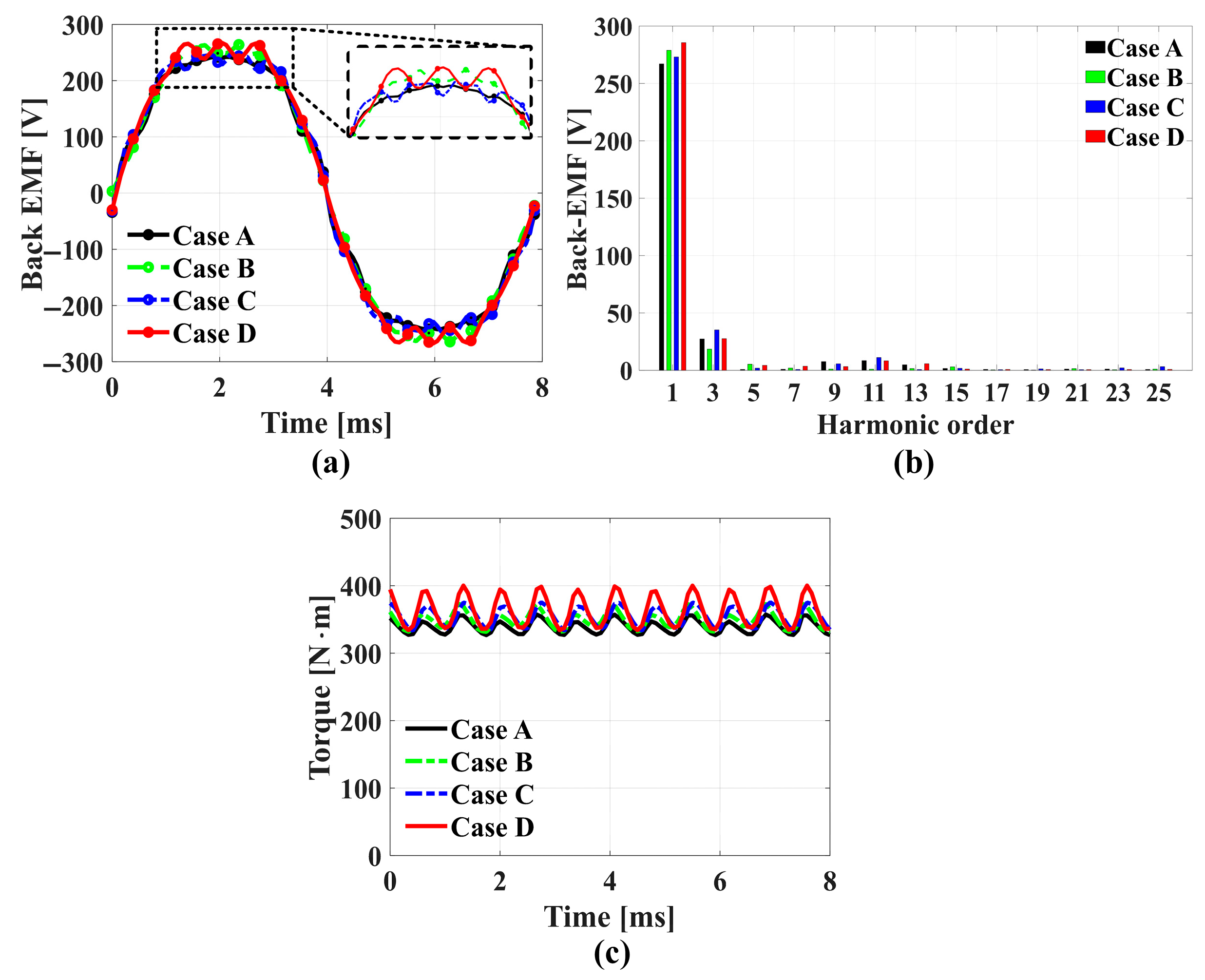
Figure 5a shows the phase-A back-EMF waveforms of the WFSM under no-load conditions for Cases A through D. Among them, Cases B and D—where GOES is applied to stator teeth or both stator and rotor teeth—exhibit the highest peak amplitudes, showing 4.2% and 6.9% improvements, respectively, over Case A. The corresponding harmonic spectra are shown in
Figure 5b, confirming the increase in fundamental component magnitude for these two cases.
Figure 5c compares the torque output under identical stator current excitation (138 Arms). Cases B and C, which involve partial GOES application, show torque improvements of 3.6% and 4.3%, respectively, over the baseline Case A. Case D, which incorporates GOES in both stator and rotor teeth, achieves the highest torque increase of 7.7%, indicating the benefit of simultaneous GOES application in both components.
3.2. Core Loss Analysis of GOES- and NOES-Based WFSMs
Core loss is a critical factor affecting the energy-conversion efficiency of electrical machines and consists mainly of hysteresis and eddy-current losses. Hysteresis loss originates from the repetitive reversal of magnetic domains, while eddy-current loss is caused by time-varying magnetic fields that induce circulating currents within the steel laminations.
For accurate estimation, the flux density must be decomposed into tangential (
Bₜ) and radial (
Bᵣ) components, and their harmonic contents must be extracted via FFT. For NOES, the core loss is computed using the following formulation [
15]:
where
i represents the harmonic order, N indicates the highest harmonic order,
Vcore denotes the volume of the electrical steel,
ρsteel refers to the mass density, and
Aconst represents the weighting factor depending on the axial ratio. A value of 1 is assigned to
Aconst for alternating magnetic fields, and a value of 2 is assigned for rotating magnetic fields in the loss calculation.
kh and
ke signify the hysteresis and eddy current coefficients, respectively. In addition,
Bt and
Br represent the tangential and radial directions of the magnetic flux density, respectively, and
fi denotes the frequency corresponding to the harmonic order.
Due to its anisotropic nature, GOES requires separate treatment for flux components in the rolling and transverse directions. Its core loss is computed using [
16]:
where
kh_rolling,
ke_rolling, and
Brolling refer to the hysteresis, eddy current, and magnetic flux densities in the GOES rolling direction, respectively. Meanwhile,
kh_trans.,
ke_trans., and
Btrans. denote the hysteresis coefficient, the eddy current coefficient, and magnetic flux density in the transverse direction, respectively.
Figure 6 shows the core loss density distribution for each design case. Total core losses are summarized in
Table 2. Among all cases, Case C exhibited the highest core loss. Although applying GOES to the rotor teeth reduced rotor loss, the stator core loss increased due to enhanced air-gap flux density. In contrast, Case B—where GOES was applied only to the stator teeth—achieved the lowest total core loss. Considering both the improved back-EMF and torque performance, along with moderate core loss, Case D was selected as the optimal configuration for further optimization.
4. Multi-Objective Optimization of the Hybrid WFSM
4.1. Selection of Design Variables and Engineering Constraints
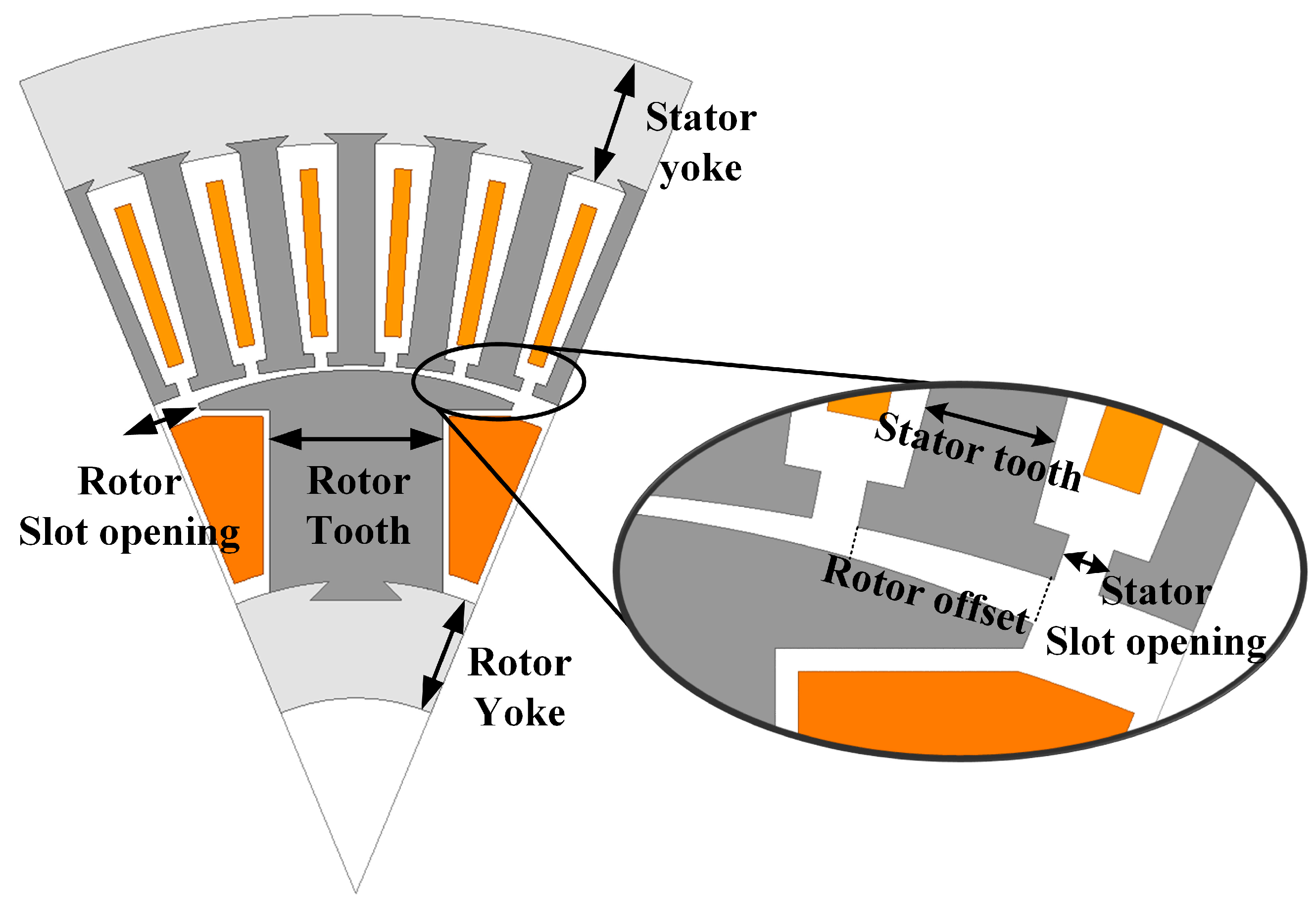
To optimize the electromagnetic performance of Case D, key geometric dimensions of both the stator and rotor were selected as design variables. The selected variables are the parameters that are mainly changed to improve the performance of WFSM [
17]. These include the yoke length, tooth width, and slot opening for each side.
Figure 7 illustrates the locations of these variables, while
Table 3 summarizes their respective design bounds.
The optimization aims to maximize power density while simultaneously improving efficiency—two critical performance metrics for traction motors in xEV applications [
18,
19,
20]. To ensure practical feasibility and manufacturability, the design space was bounded by the following constraints: torque ripple ≤ 10%, terminal voltage ≤ 500 V, stator slot fill factor ≤ 40%, and rotor slot fill factor ≤ 70%.
4.2. Optimization Methodology Using a Meta-Model and Genetic Algorithm
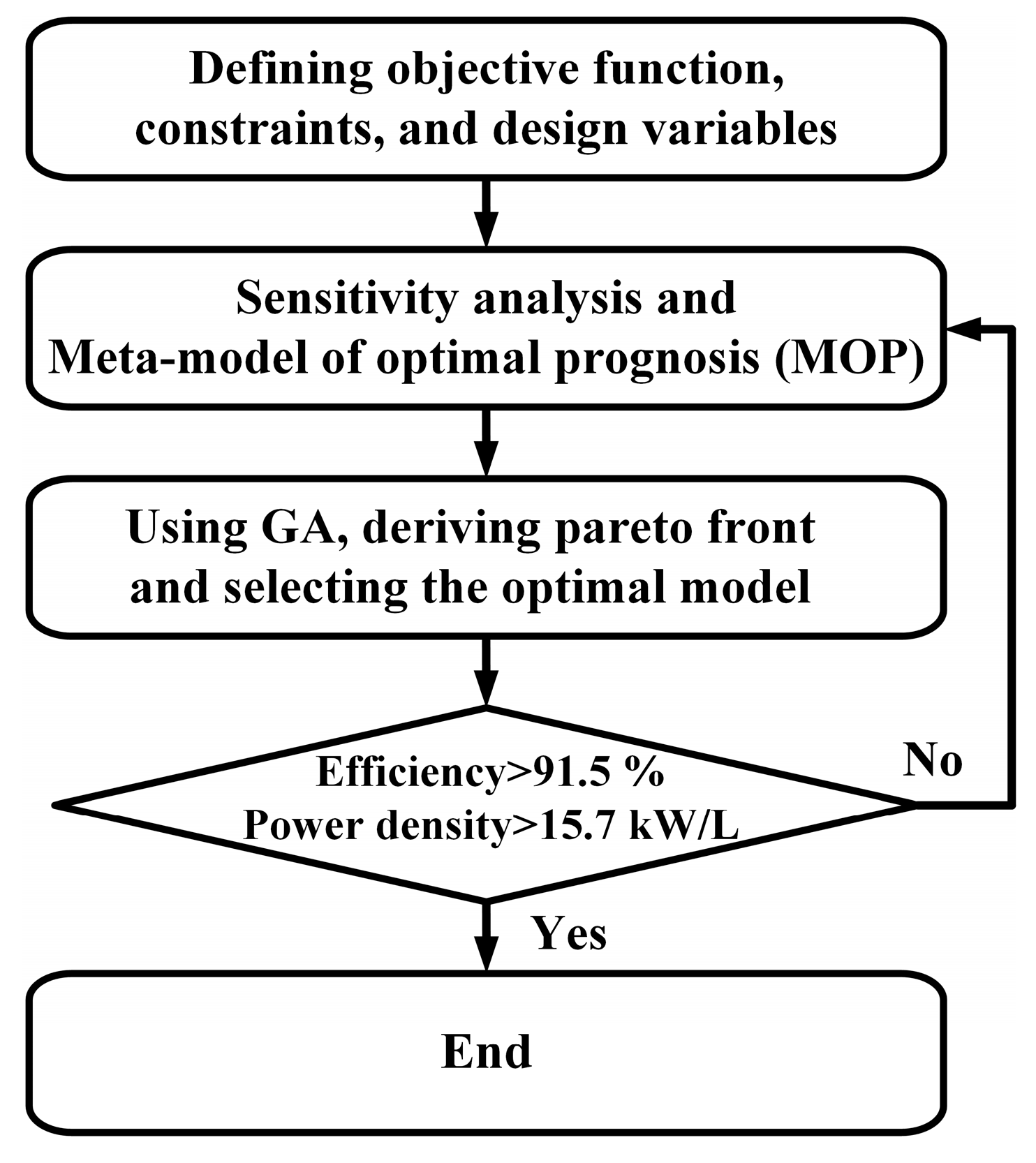
The optimization process employed a structured three-stage methodology, as illustrated in
Figure 8 [
21]. First, sensitivity analysis was conducted using the LHS technique, which ensures uniform and probabilistically balanced coverage of the design space. This approach divides each design variable range into equally probable intervals, enabling efficient and comprehensive exploration. The sampled results were then used to evaluate the correlation between design variables and output performance metrics. Second, a meta-model was constructed to interpolate the relationship between inputs and outputs, significantly reducing computational cost by approximating the results of full FEA. Finally, a GA was applied to identify the global optimum design. The GA parameters were set as follows: a population size of 16, a crossover rate of 0.5, a mutation rate of 0.12, and 625 generations. This configuration was chosen to maintain a balance between exploration of the search space and convergence toward optimal solutions. The final candidate designs obtained from the GA were validated using full FEA simulations to confirm improvements in both power density and efficiency.
5. Results and Discussion
The final design was selected from the Pareto front obtained through the GA-based multi-objective optimization process. The optimal WFSM geometry includes a stator yoke length of 17.6 mm, a tooth width of 6.2 mm, and a slot opening of 1.5 mm. For the rotor, the yoke length is 19.6 mm, tooth width 25.2 mm, slot opening 15.4 mm, and rotor offset 24.9 mm.
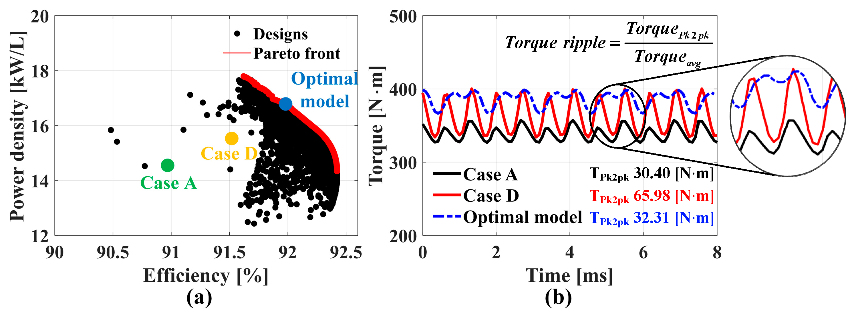
Figure 9a presents the Pareto front, illustrating the trade-off between power density and efficiency under the same current condition. In this study, the optimal model on the Pareto front was selected based on a weighted trade-off, with a higher priority assigned to power density. This decision reflects the fact that while efficiency is important, lightweight design is a critical requirement in traction motors for xEVs, making power density a more practical performance indicator in real-world applications.
The optimized model achieves a 1.0% improvement in efficiency over Case A and 0.42% over Case D, while power density increases by 13.97% and 6.4%, respectively.
Figure 9b compares the torque waveforms of the optimized model and Cases A and D. The optimized design shows a torque ripple of 8.4%, which is 0.6% lower than Case A and 10% lower than Case D.
Table 4 summarizes the performance at two operating points (800 rpm and 3500 rpm). Efficiency was calculated based on copper and core losses. The optimized WFSM outperforms the initial design at both low and high speeds due to reduced copper loss—resulting from lower current—and decreased core loss due to the superior magnetic properties of GOES. Specifically, the efficiency improves by 1.7% at 800 rpm and 0.5% at 3500 rpm.
These results confirm the effectiveness of the proposed optimization strategy in enhancing the overall performance of the WFSM.
6. Conclusions
This study proposed a novel design methodology to improve the power density and efficiency of a WFSM by selectively applying GOES. Based on an analysis of magnetic flux behavior, alternating and rotating field regions within the stator and rotor were identified to determine where the anisotropic properties of GOES could be effectively utilized.
Four machine configurations were developed according to the GOES application area. Among them, Case D—with GOES applied to both the stator and rotor teeth—demonstrated superior electromagnetic performance and was selected for further optimization. To enhance both power density and efficiency, sensitivity analysis was performed using Latin Hypercube Sampling (LHS), followed by meta-model construction and GA-based global optimization.
The optimized design showed a 13.7% increase in torque compared to Case A, based on the rated operating condition and same current (138 Arms), as illustrated in
Figure 9b. In addition, torque ripple was reduced to 8.4%. GOES application also led to a notable reduction in core loss, which is expected to suppress heat generation and extend the machine’s operational life.
The proposed approach offers a pathway for compact and lightweight WFSM designs, potentially enabling shorter stack lengths and reduced copper loss without compromising performance. Furthermore, the improved efficiency, power density, and reduced core losses make the machine particularly well suited for electric vehicle applications such as electric buses and industrial utility EVs, where thermal management and cost-effectiveness are key concerns.
It should be noted that all performance evaluations in this study were based on electromagnetic simulations. Mechanical, thermal, and inverter-related losses were not included and will be considered in future experimental validations.
Future work involves prototyping the optimized WFSM and conducting detailed experimental validation under IEC-standard test conditions to verify the simulation results, including back-EMF, torque, and core-loss measurements. The applicability of selective GOES integration in other electric-machine topologies will also be explored.
Author Contributions
Conceptualization, K.-H.S., K.-T.Y. and J.-Y.C.; methodology, K.-H.S., K.-T.Y., J.-B.P. and J.-Y.C.; software, K.-H.S., S.-W.K. and H.-R.B.; validation, K.-H.S., K.-T.Y. and J.-Y.C.; writing—original draft preparation, K.-H.S., K.-T.Y. and J.-Y.C.; writing—review and editing, K.-H.S. and J.-Y.C.; supervision, J.-Y.C. and K.-H.S.; funding acquisition, J.-Y.C. and K.-H.S. All authors have read and agreed to the published version of the manuscript.
Funding
Following are results of a study on the “Regional Innovation System & Education (RISE)” Project, supported by the Ministry of Education and Gyeonsangnam-do (RISE Center).
Data Availability Statement
The original contributions presented in this study are included in the article. Further inquiries can be directed to the corresponding authors.
Conflicts of Interest
The authors declare no conflict of interest.
References
- Park, H.-J.; Lim, M.-S. Design of High Power Density and High Efficiency Wound-Field Synchronous Motor for Electric Vehicle Traction. IEEE Access 2019, 7, 46677–46685. [Google Scholar] [CrossRef]
- Accetta, A.; Cirrincione, M.; Di Piazza, M.C.; La Tona, G.; Luna, M.; Pucci, M. Analytical formulation of a maximum torque per ampere (MTPA) technique for SynRMs considering the magnetic saturation. IEEE Trans. Ind. Appl. 2020, 56, 3846–3854. [Google Scholar] [CrossRef]
- Di Nardo, M.; Marfoli, A.; Degano, M.; Gerada, C. Rotor slot design of squirrel cage induction motors with improved rated efficiency and starting capability. IEEE Trans. Ind. Appl. 2022, 58, 3383–3393. [Google Scholar] [CrossRef]
- Seol, H.-S.; Jeong, J.-M.; Lee, J.; Jin, C.-S. Current control of WRSM considering magnetic saturation phenomenon. IEEE Trans. Magn. 2016, 52, 8204104. [Google Scholar] [CrossRef]
- Kim, Y.; Nam, K. Copper-loss-minimizing field current control scheme for wound synchronous machines. IEEE Trans. Power Electron. 2016, 32, 1335–1345. [Google Scholar] [CrossRef]
- Périgo, E.A.; Tremelling, D. Grain-oriented magnetic particles for energy applications. IEEE Magn. Lett. 2018, 9, 5104004. [Google Scholar] [CrossRef]
- Rebhaoui, A.; Randi, S.-A.; Demian, C.; Lecointe, J.-P. Analysis of flux density and iron loss distributions in segmented magnetic circuits made with mixed electrical steel grades. IEEE Trans. Magn. 2021, 58, 2000711. [Google Scholar] [CrossRef]
- Lee, J.H.; Kim, Y.-J.; Lim, D.-K.; Jung, S.-Y. Design of Wound-Field Rotor Synchronous Motor for Electric Vehicles using Grain-oriented Electrical Steel Sheet to Mitigate Back-Electromotive Force. J. Magn. 2024, 29, 321–324. [Google Scholar] [CrossRef]
- Oh, H.-J.; Cho, J.-H.; Hwang, Y.-H.; Kim, Y.; Jung, S.-W.; Jung, S.-Y. Performance Improvement of Wound Field Synchronous Motor for EV Propulsion applying Grain Oriented Electrical Steel. IEEE Trans. Magn. 2024, 61, 8200704. [Google Scholar] [CrossRef]
- Talebi, D.; Gardner, M.C.; Sankarraman, S.V.; Daniar, A.; Toliyat, H.A. Electromagnetic design characterization of a dual rotor axial flux motor for electric aircraft. IEEE Trans. Ind. Appl. 2022, 58, 7088–7095. [Google Scholar] [CrossRef]
- Li, Z.; Li, Y.; Qin, Y.; Zeng, L.; Li, J.; Pei, R. Analysis of magnetomechanical properties at the tooth–yoke embedding position in grain-oriented electrical steel electric motors. IEEE Trans. Magn. 2024, 60, 2001005. [Google Scholar]
- Son, J.-C.; Kim, J.-Y.; Choi, J.-W.; Lim, D.-K.; Yeo, H.-K. Performance enhancement of the IPMSM for HEV applications using grain-oriented electrical steel and design optimization. IEEE Access 2022, 10, 46599–46607. [Google Scholar] [CrossRef]
- Geng, W.; Hou, J.; Li, Q. Electromagnetic analysis and efficiency improvement of axial-flux permanent magnet motor with yokeless stator by using grain-oriented silicon steel. IEEE Trans. Ind. Appl. 2021, 58, 8200905. [Google Scholar] [CrossRef]
- Nguyen, M.-D.; Hoang, D.-T.; Kim, S.-M.; Jung, W.-S.; Shin, K.-H.; Kim, Y.-J.; Choi, J.-Y. Nonlinear Modeling and Analysis Considering Coupling Stator Flux of Wound-Rotor Synchronous Motors. In Proceedings of the 2024 International Conference on Electrical Machines (ICEM), Torino, Italy, 1–4 September 2024; pp. 1–7. [Google Scholar]
- Shin, K.-H.; Hong, K.; Cho, H.-W.; Choi, J.-Y. Core loss calculation of permanent magnet machines using analytical method. IEEE Trans. Appl. Supercond. 2018, 28, 5205005. [Google Scholar] [CrossRef]
- Denis, N.; Takeda, S.; Fujitani, K.; Fujisaki, K.; Odawara, S. Anisotropic magnetic core for the iron loss reduction of permanent magnet synchronous motor. J. Magn. Soc. Jpn. 2018, 42, 62–71. [Google Scholar] [CrossRef]
- Lee, J.; Kim, J.; Luu, P.T.; Hwang, S. Concept design and optimization methodology of a wound field synchronous motor for commercial vehicle applications. In Proceedings of the IEEE Energy Conversion Congress and Exposition (ECCE), Nashville, TN, USA, 29 October–2 November 2023; pp. 4330–4337. [Google Scholar]
- Sun, X.; Shi, Z.; Lei, G.; Guo, Y.; Zhu, J. Multi-objective design optimization of an IPMSM based on multilevel strategy. IEEE Trans. Ind. Electron. 2020, 68, 139–148. [Google Scholar] [CrossRef]
- Fatemi, A.; Ionel, D.M.; Popescu, M.; Chong, Y.C.; Demerdash, N.A. Design optimization of a high torque density spoke-type PM motor for a formula E race drive cycle. IEEE Trans. Ind. Appl. 2018, 54, 4343–4354. [Google Scholar] [CrossRef]
- Xue, X.; Cheng, K.W.E.; Ng, T.W.; Cheung, N.C. Multi-objective optimization design of in-wheel switched reluctance motors in electric vehicles. IEEE Trans. Ind. Electron. 2010, 57, 2980–2987. [Google Scholar] [CrossRef]
- Wu, L.; Li, Y.; Lu, Q. Detent Force Fast Optimization Method of Modular Permanent-Magnet Linear Synchronous Motors. IEEE Trans. Ind. Electron. 2024, 71, 16191–16199. [Google Scholar] [CrossRef]
| Disclaimer/Publisher’s Note: The statements, opinions and data contained in all publications are solely those of the individual author(s) and contributor(s) and not of MDPI and/or the editor(s). MDPI and/or the editor(s) disclaim responsibility for any injury to people or property resulting from any ideas, methods, instructions or products referred to in the content. |
© 2025 by the authors. Published by MDPI on behalf of the World Electric Vehicle Association. Licensee MDPI, Basel, Switzerland. This article is an open access article distributed under the terms and conditions of the Creative Commons Attribution (CC BY) license (https://creativecommons.org/licenses/by/4.0/).


 ,
, 

