1. Introduction
Magnetically coupled wireless power transfer (MC-WPT) technology has gained extensive application in recent years across transportation [
1], electronic devices [
2], and implantable medical devices [
3] due to its safety and flexibility. To address diverse application scenarios, major wireless charging alliances have introduced standards such as Qi, A4WP, and PMA [
4]. The variability among these standards and their differing power levels pose challenges to the compatibility of wireless charging platforms.
The core challenge in achieving reliable multi-frequency, multi-load wireless power supply lies in efficiently generating composite frequency excitation signals to drive multi-resonant circuits. The existing literature proposes various solutions. For instance, a recent study [
5] has developed an MC-WPT system driven by multiple superimposed inverters, enabling multi-frequency mixed power output at the inverter terminals. Additionally, inverters operating at distinct frequencies are employed in [
6] to simultaneously support receivers complying with different standards. Ref. [
7] adopts a multi-transmitter and multi-receiver configuration, proposing a multiphase, multifrequency MC-WPT system capable of supplying multiple loads. This design effectively mitigates sensitivity to load misalignment and optimizes multi-objective power distribution and output stability through joint phase-frequency regulation. However, the parallel operation of multiple inverters across [
5,
6,
7] complicates system architecture and induces nonlinear increases in power loss across transmission channels, hindering system miniaturization and practical implementation. While existing single-inverter systems can utilize fundamental and harmonic frequencies to establish multiple energy transfer paths, independent energy regulation across multiple receivers remains difficult as reported in [
8,
9].
To address this, a Multi-Frequency Multi-Amplitude (MFMA) modulation method is proposed in [
10], which enhances DC voltage utilization by 44.88% via a phase optimization algorithm, albeit with complex modulation. In recent work [
11], a Sinusoidal Pulse Width Superposition Modulation (SPWSM) method is introduced to enable independent receiver regulation; however, it substantially increases inverter switching frequency, leading to elevated power device losses. A delta-sigma modulation scheme is presented in [
12] that significantly reduces switching frequency but requires complex online computation. Consequently, modulation methods for multi-frequency signals emerge as a critical issue in multi-load systems.
To meet the constant-voltage (CV)/constant-current (CC) requirements across diverse applications, numerous studies have proposed various compensation network topologies. For single-frequency multi-load systems, two primary approaches are typically employed: composite network design on the receiver side or transmitter side. A switched compensation network (SS/PS or SP/PP) using three switches to achieve CV/CC output was pioneered in [
13]. In recent work [
14], topology switching between TS/SP and S/SP configurations was introduced, enabling CC/CV output without DC-DC converters while reducing sensitivity to coupling coefficients through parameter decoupling; however, transient surges occur during switching. A variable static S-T/FC compensation topology is proposed in [
15] to achieve CC/CV output via single-switch control, which simplifies switching circuitry but exhibits insufficient misalignment tolerance. As reported in [
16], LCL-LCL and LCL-S composite topologies are utilized for CC/CV output, respectively, yet these designs suffer from parameter sensitivity and vulnerability to coil resistance.
For multi-frequency multi-load systems, a Multi-Frequency Resonant Compensation (MFRC) network was developed in [
17] to achieve multi-resonant frequencies in multi-pickup WPT systems, with the aim of enhancing efficiency and reducing reactive power. However, its complex structure and challenging parameter design make it susceptible to cross-frequency interference, compromising output power. In recent research [
18], a Superposed Dual-Frequency Modulation (SDFM) method was proposed for independent load power regulation, which employs an LC parallel resonant network on the secondary side to suppress cross-frequency interference, though its applicability is limited. Notably, the systems described in [
17,
18] fail to achieve CC/CV output characteristics.
To address this, a primary-side Multi-Frequency Constant-Current (MFCC) compensation network was introduced in [
19], enabling the transmitter to operate as a constant-current source. This in turn allows receivers to deliver either CC or CV output to meet diverse load demands. Nevertheless, achieving such CC/CV output requires distinct receiver-side topologies, and the design of compensation network components remains complex. Recent work [
20] has proposed a Hybrid-Frequency Multi-Load (HFML) WPT system, which can simultaneously power two independently regulated loads via a primary-side hybrid-frequency compensation network. However, this approach is confined to dual-frequency dual-load scenarios and offers only a limited range of load regulation.
In summary, to achieve simultaneous multi-frequency output in multi-frequency multi-load MCR-WPT systems while minimizing system volume, this work employs hybrid-frequency superposition modulation, enabling concurrent transmission of multiple frequency signals to support diverse application scenarios. The transmitter incorporates a modified T-type topology integrating series resonant compensation with LCC resonant compensation, while the receiver side adopts an LCC structure, permitting effective regulation across wide load ranges and achieving independent power regulation. This approach enhances flexibility in power distribution among different receivers.
2. System Topology and Modeling
Conventional multi-frequency multi-load magnetically coupled resonant wireless power transfer (MCR-WPT) systems transmit electrical energy through resonant magnetic coupling. As illustrated in
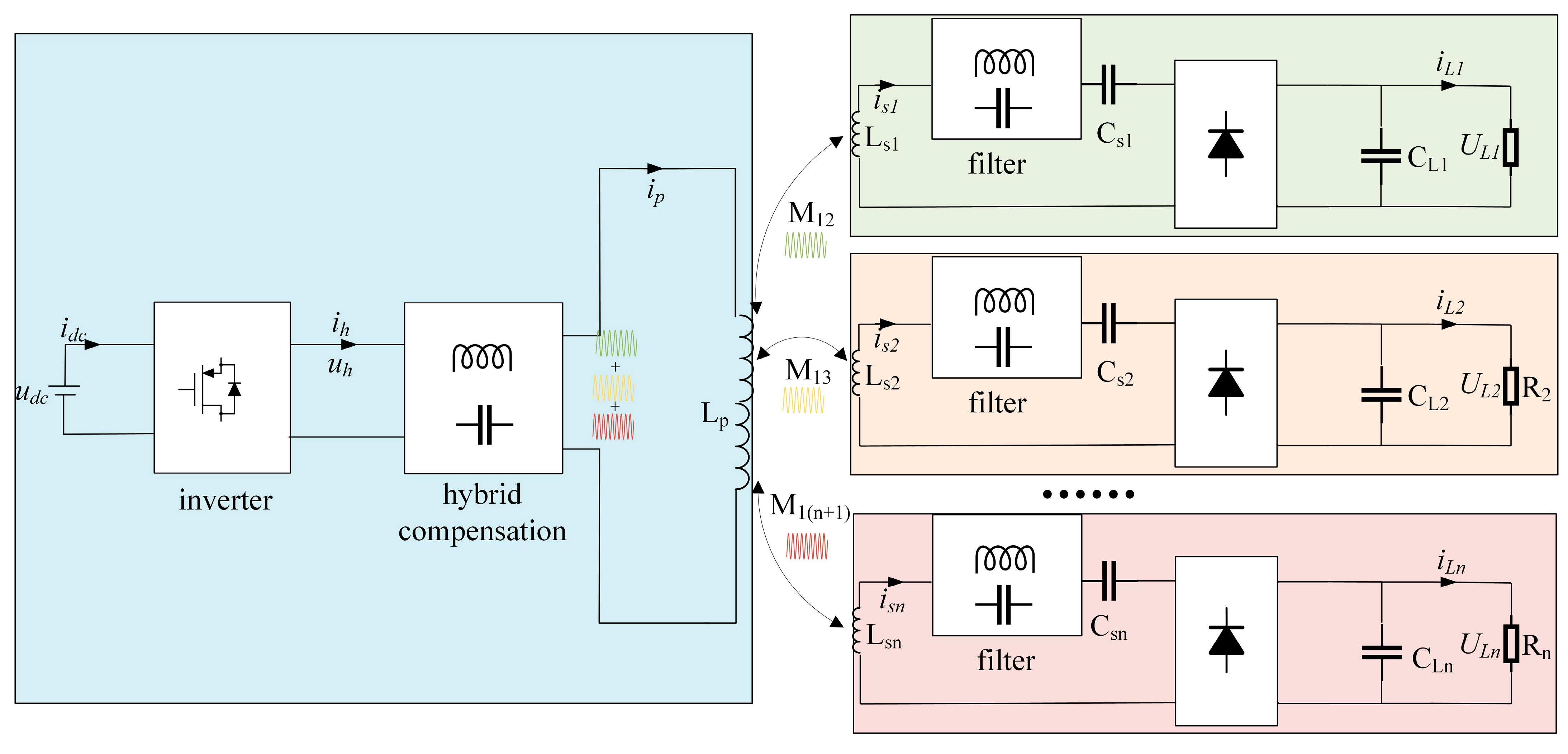
Figure 1, the system primarily comprises a DC power source, high-frequency inverter circuit, transmitter-side resonant network, rectifiers, receiver-side resonant networks, and loads. The DC power source is converted into a high-frequency AC source through the inverter. After partial reactive power compensation via the primary-side hybrid compensation network, electrical energy is transferred from the transmitting coil to receiving coils. Each receiving coil incorporates a filtering circuit; when the filtering network exhibits effective frequency-selective characteristics, it can selectively receive signals at different frequencies. Finally, rectifiers supply power to respective loads, achieving reliable multi-frequency multi-load power delivery.
For medium-to-low-power charging systems, a single transmitting coil may be employed on the primary side, significantly simplifying system architecture. Notably, the transmitter and receiver designs enable stable constant-current (CC) and constant-voltage (CV) outputs without requiring real-time communication, thereby satisfying diverse load requirements. This approach not only enhances system flexibility and adaptability but also provides a reliable power transfer solution for practical applications.
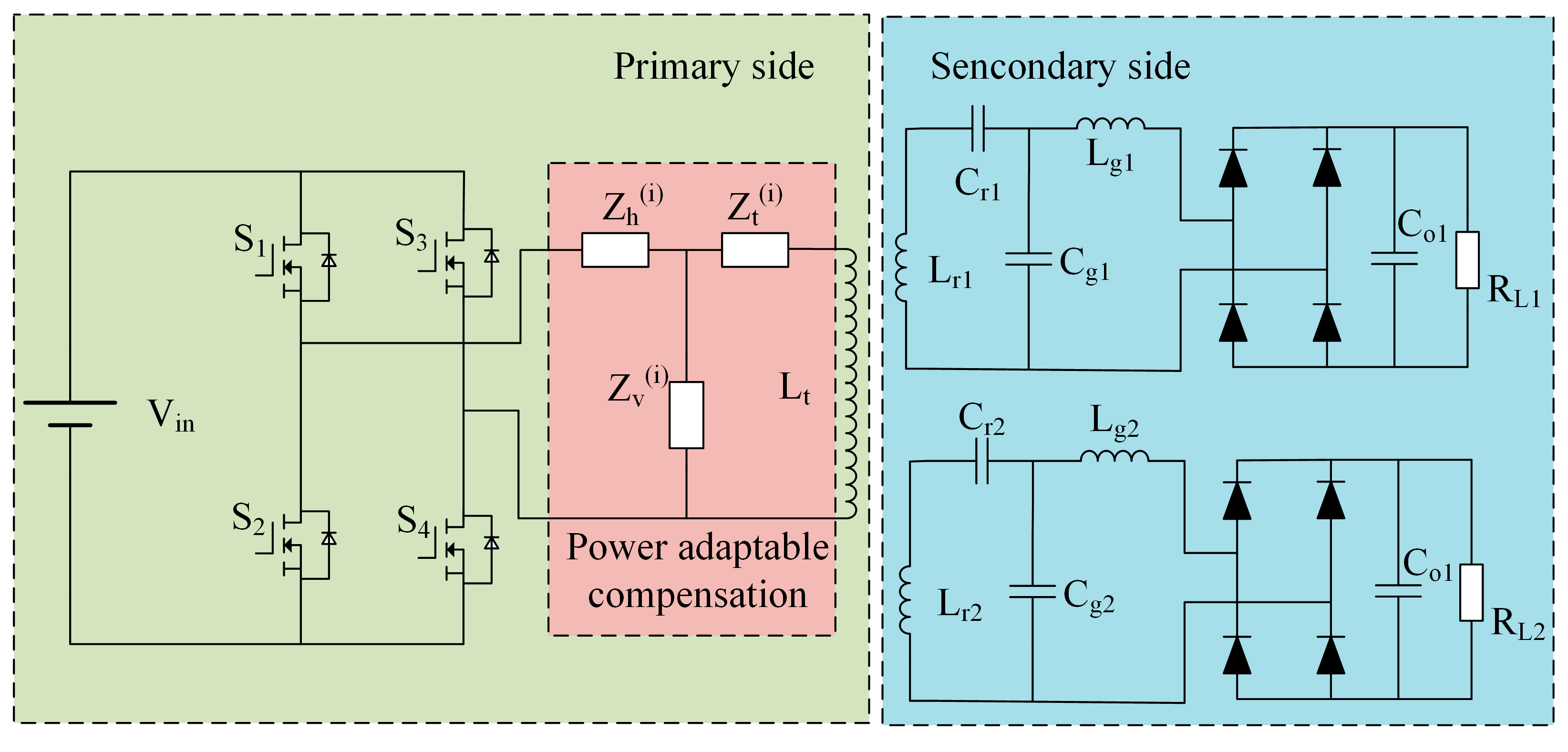
To simplify system analysis, a dual-frequency dual-load MCR-WPT system is proposed as illustrated in
Figure 2 below.
2.1. Hybrid-Frequency Modulation Methodology
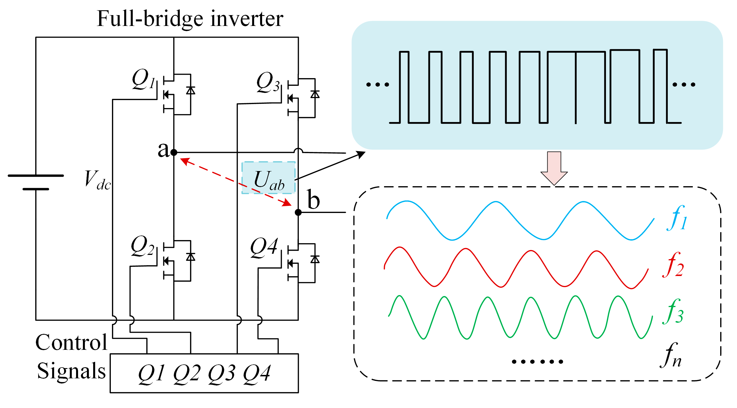
To satisfy the frequency requirements of diverse loads, this design employs a hybrid-frequency-modulation-based PWM control method as depicted in
Figure 3. The implementation utilizes a triangular carrier signal, with the modulation signal being a composite waveform formed by superimposing sinusoidal waves whose amplitudes and frequencies are independently adjustable. These sinusoidal components are expressed in Equation (1).
In Equation (1), ur1(t), ur2(t),…, urn(t) represent n distinct modulation signals, while ur(t) denotes the composite modulated signal. Here, a1, a2,…, an correspond to the amplitudes of individual modulation components, and f1, f2,…, fn align with the inherent resonant frequencies of respective receiver-side circuits.
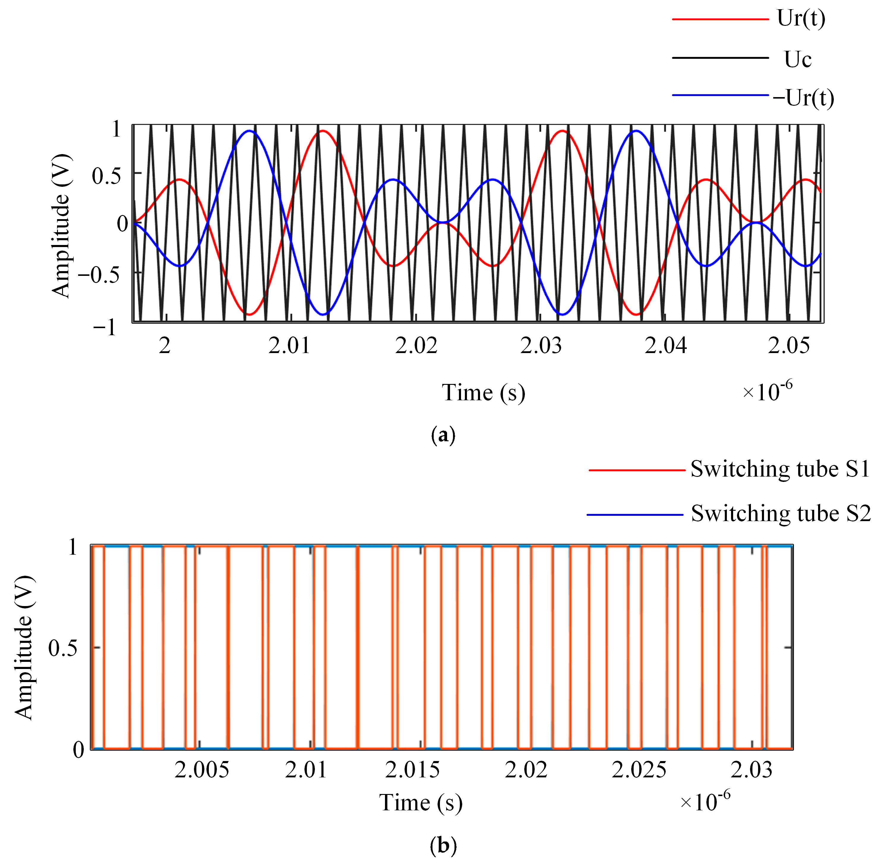
For dual-frequency dual-load WPT systems, a novel hybrid-frequency modulation method is proposed. This approach employs two modulation signals with equal amplitude and opposite polarity, which are compared against a high-frequency triangular carrier wave. The comparison generates complementary driving signals for switch pairs (Q1 and Q4, Q2 and Q3), thereby enabling the inverter to produce pulsed outputs. This mechanism efficiently converts DC input into AC power with programmable frequency and amplitude, offering both flexible control strategies and high operational efficiency.
To elucidate the operating principles, this work demonstrates a hybrid modulation scheme combining 59 kHz and 151 kHz sinusoidal components.
Figure 4 illustrates the modulation mechanism:
2.2. Compensation Network Design Philosophy
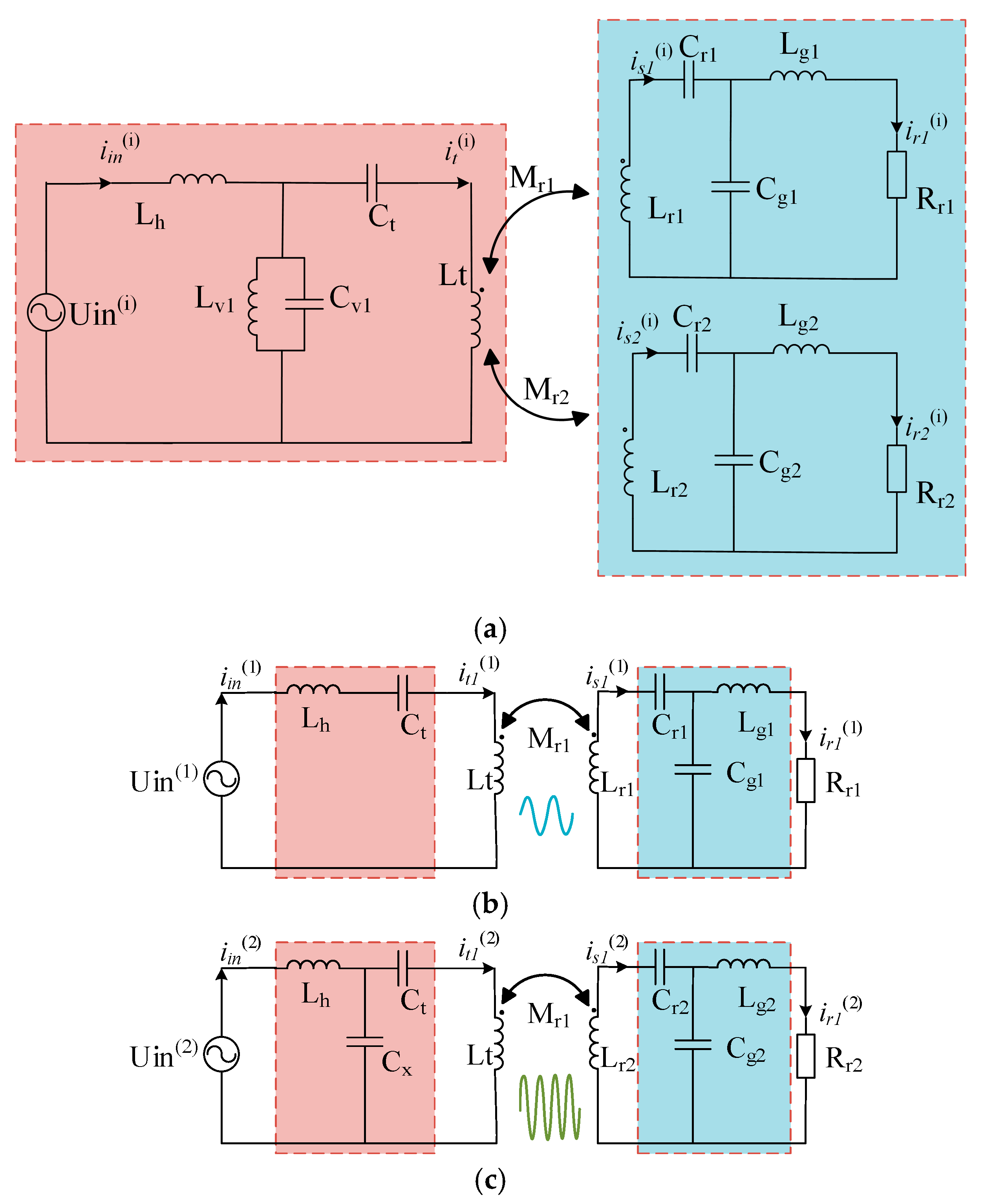
The circuit structure: Among the four fundamental compensation topologies in inductive wireless power transfer (WPT) systems, the Series–Series (S-S) compensation network exhibits superior structural simplicity compared to alternative configurations. This study therefore prioritizes the analysis of constant-current (CC) and constant-voltage (CV) compensation design principles based on the S-S topology, ultimately proposing a hybrid compensation network architecture capable of achieving dual-mode CC/CV operation.
Figure 5 illustrates the equivalent circuits of the S-S-compensated WPT system under distinct excitation conditions. The analytical framework initiates with parametric modeling of the S-S network’s inherent characteristics, followed by systematic derivation of CC/CV constraint equations. This methodology establishes theoretical foundations for subsequent integration of hybrid compensation components while maintaining compatibility with conventional S-S configuration advantages.
When terminals ab are configured as a voltage-source input and the circuit operates in resonant state, the current gain
HVI of the system can be derived from (KVL) as follows:
where
IL denotes the RMS value of the output current and
Uin represents the RMS value of the input voltage. Equation (2) reveals that the S-S compensated system achieves constant-current output when maintaining fixed operating frequency, mutual inductance coefficient, and input voltage amplitude.
Analogously, when terminals ab are configured as a current-source input under resonant operation, the voltage gain
HIV can be derived from KVL:
In Equation (3), Iin represents the RMS value of the input current, and UL denotes the RMS value of the output voltage. The analysis demonstrates that the S-S compensated system achieves constant-voltage (CV) output when maintaining fixed operating frequency, mutual inductance coefficient, and input current amplitude.
In conclusion, the constant-voltage/constant-current (CV/CC) regulation of WPT systems can be realized through active control of input port power characteristics. This paper proposes the topology shown in
Figure 6, which incorporates a variable-structure compensation network between the voltage source and terminals ab. This network dynamically reconfigures its parameters to meet system requirements for CV/CC operation, thus enabling adaptive impedance matching across varying load conditions while preserving resonant energy transfer efficiency.
4. Simulation and Experimental Validation
To validate the operational performance of the designed dual-frequency dual-load magnetically coupled resonant wireless power transfer (MCR-WPT) system, the system was first simulated under operating frequencies of
f1 = 59 kHZ and
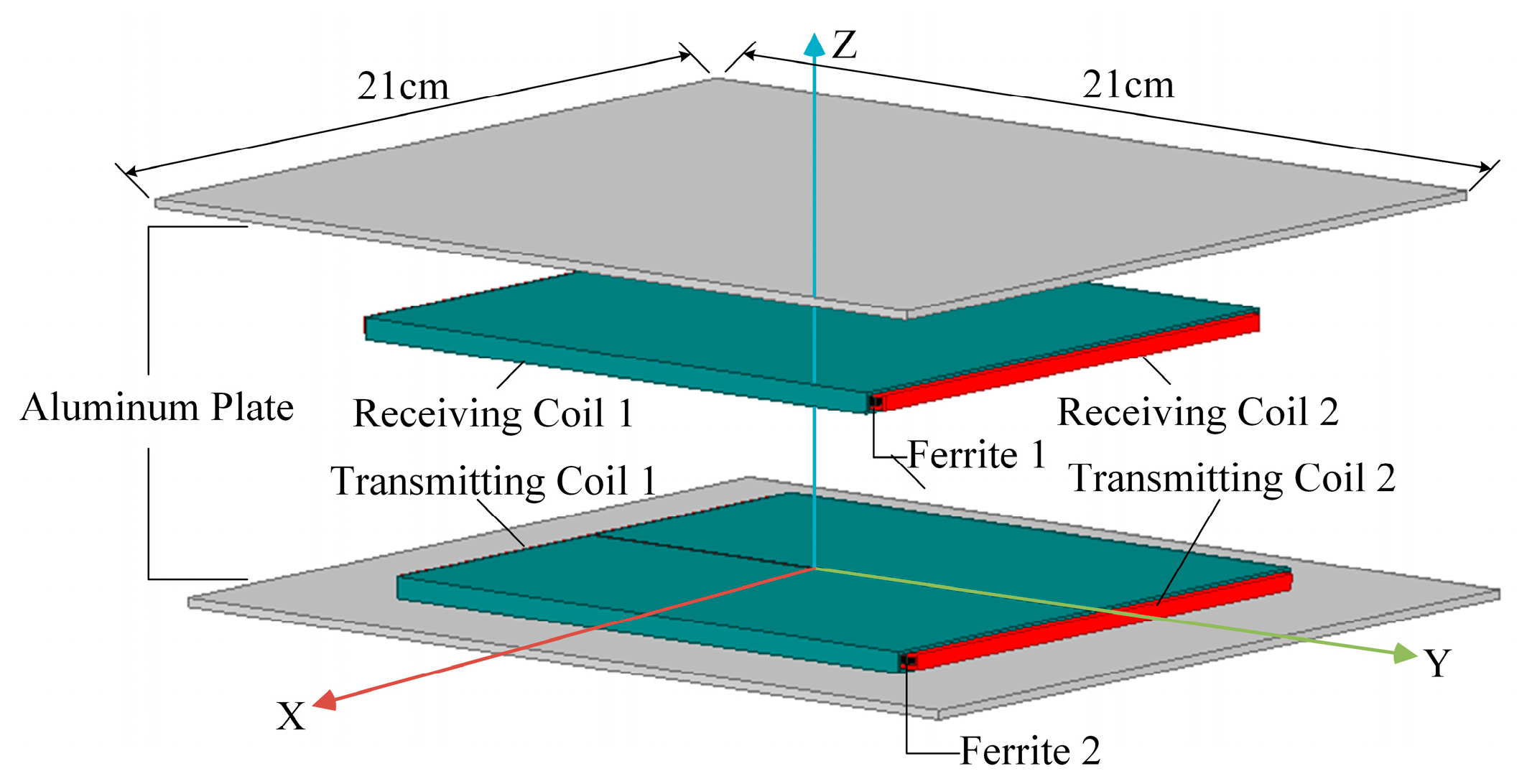
f2 = 151 kHz, with the resonant frequencies of the two secondary-side receiver circuits correspondingly set to 59 kHz and 151 kHz. A comprehensive circuit model was established using the MATLAB/Simulink platform to analyze system dynamics. Simultaneously, a laboratory prototype was constructed to experimentally verify the theoretical framework, ensuring alignment between simulation predictions and practical outcomes. Key parameters for both simulation and experimental setups, including coil geometries, compensation network configurations, and load specifications, are systematically summarized in
Table 2.
The system employs a dual-frequency superposition modulation strategy to synthesize composite signals from two distinct frequency components, which are then used to control the switching patterns of the high-frequency full-bridge inverter. This enables the generation of a dual-frequency composite voltage waveform at the inverter output terminals. Leveraging the principles of electromagnetic induction coupling and resonant synchronization, the secondary-side receiver circuits autonomously extract power through frequency-selective resonant networks. Consequently, simultaneous wireless power delivery to two independent loads operating at disparate frequencies (f1 and f2) is achieved within a single MCR-WPT architecture, demonstrating robust dual-band operational capability.
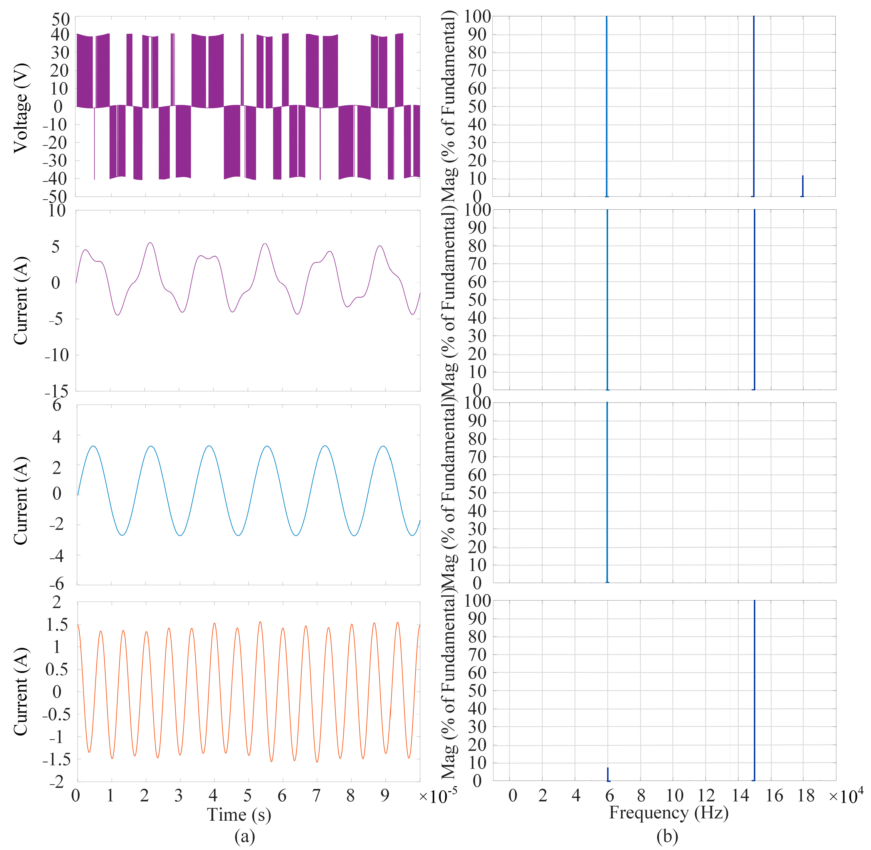
The output voltage waveform of the high-frequency inverter, along with its output current waveform and the current waveforms of the two receiver circuits operating at distinct resonant frequencies, are depicted in
Figure 14. Additionally, to validate the efficacy of dual-frequency power transmission,
Figure 14 provides the corresponding current spectral analysis diagrams of the inverter and the two load circuits, derived from simulation results, which explicitly demonstrate the frequency-selective energy transfer characteristics and spectral isolation between the 59 kHz and 151 kHz operating bands.
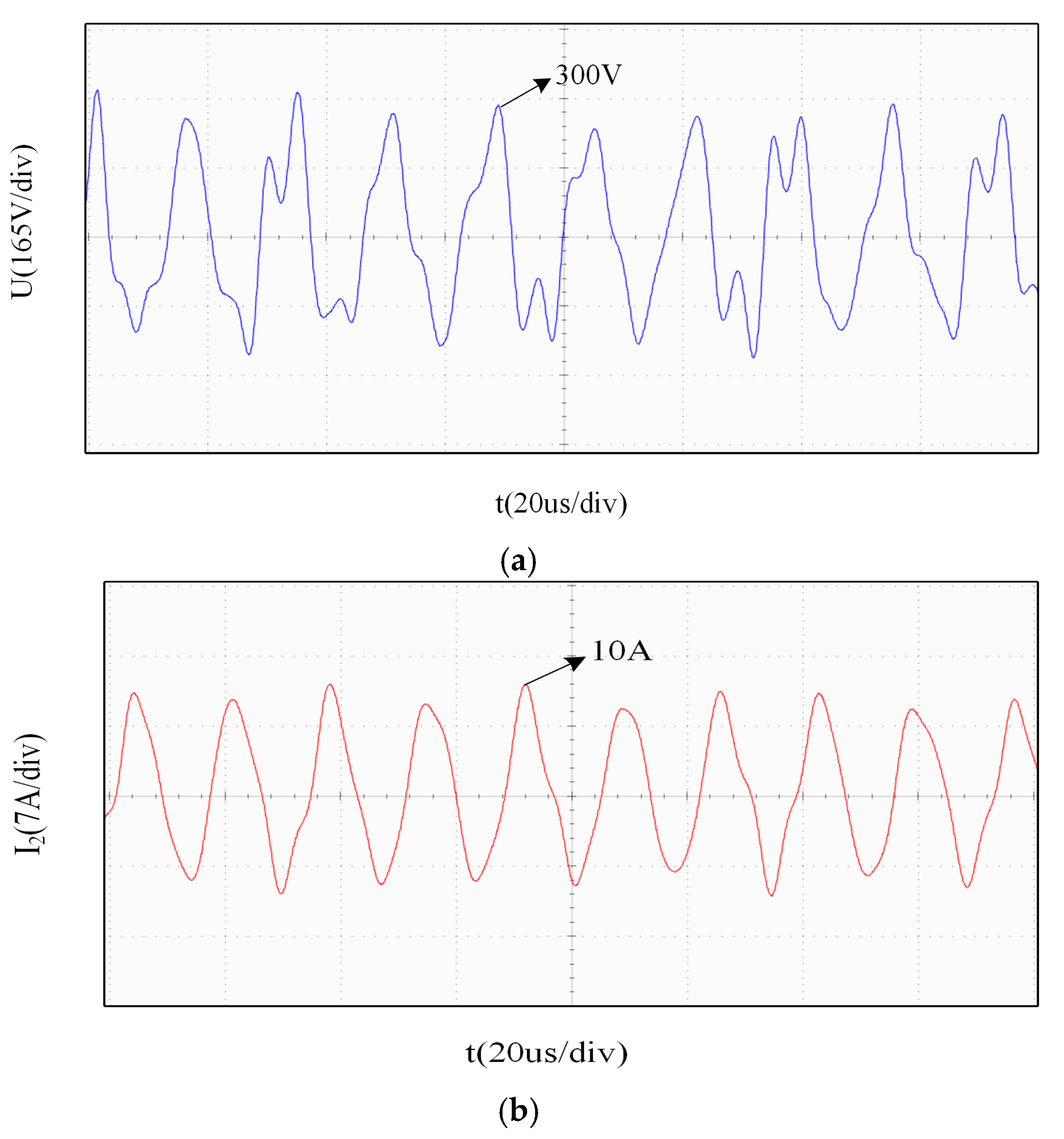
The experimental waveforms of the output voltage and current from the transmitting coil are shown in
Figure 14. It can be observed that the experimental results align well with theoretical predictions, demonstrating that the transmitter’s parameter design effectively enables the transmission of dual-frequency composite waves.
To intuitively demonstrate that the designed dual-frequency dual-load system possesses constant-voltage (CV) and constant-current (CC) characteristics, the transient response of the output power in both receiving circuits was analyzed.
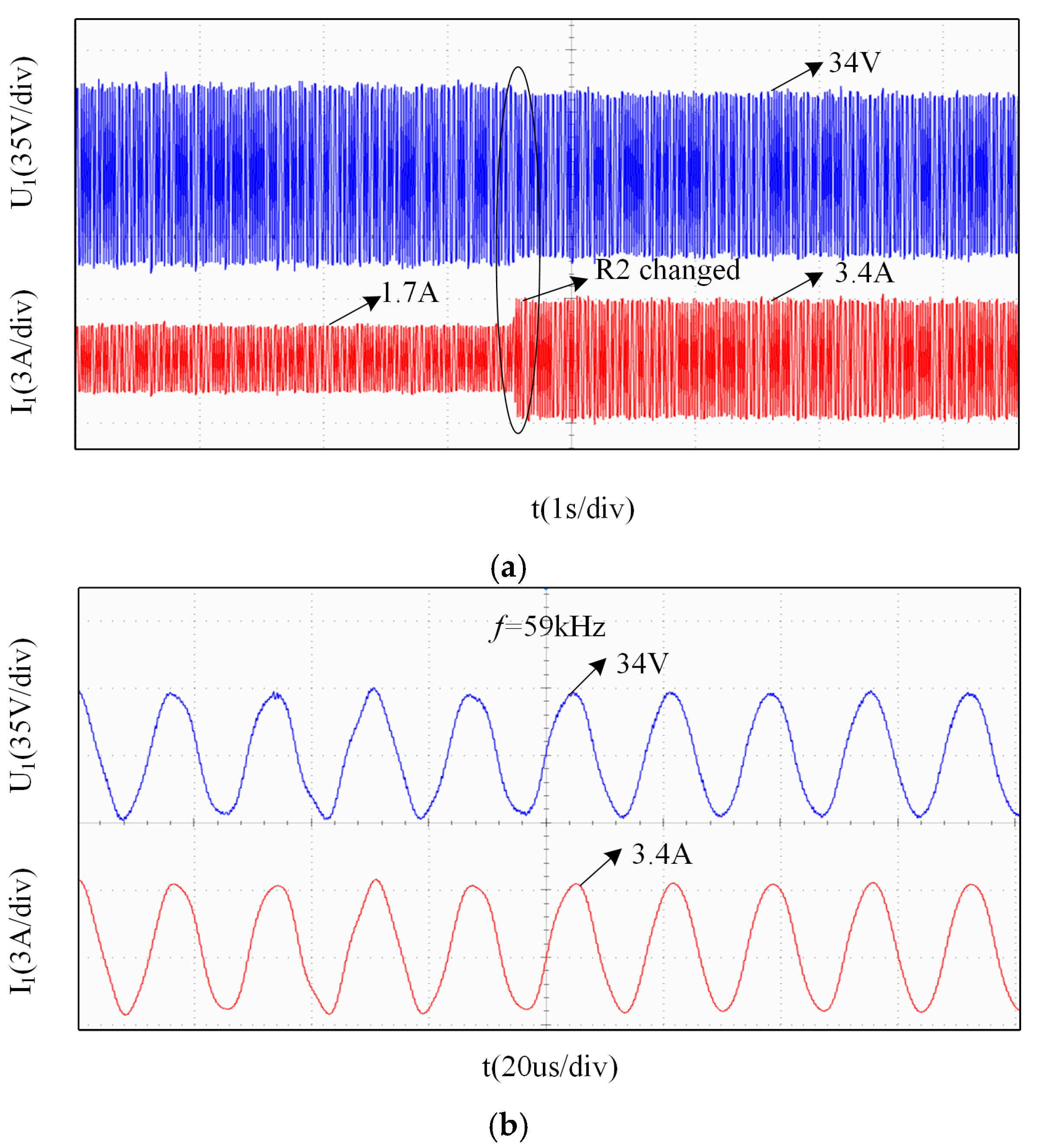
As shown in
Figure 15, the blue curve represents the voltage of Load 1, while the red curve represents the current of Load 1. In the system, at one time, Load 2 was maintained at 20 Ω, while Load 1 was switched from 20 Ω to 10 Ω. The corresponding waveform is illustrated in
Figure 16a. The voltage waveform changed from 34 V to approximately 34 V, exhibiting minimal variation and quickly stabilizing. The current waveform increased from 1.7 A to 3.4 A. Both voltage and current waveforms of Load 1 maintained good quality before and after the switching. The post-switching waveform, shown in
Figure 16b, operates at a frequency of 59 kHz.
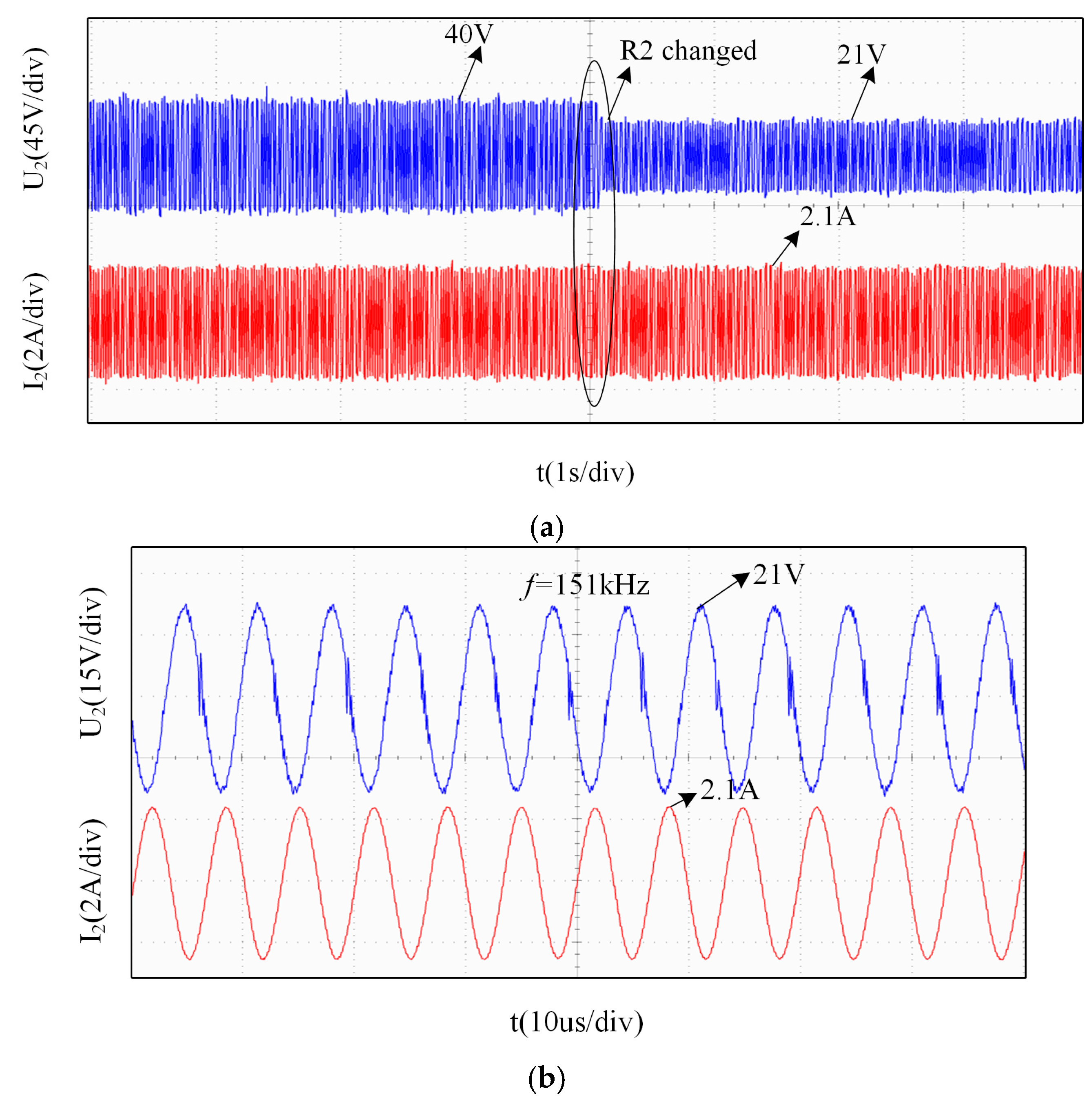
Similarly,
Figure 17 displays the blue curve as the voltage of Load 2 and the red curve as the current of Load 2. At another time, Load 1 was fixed at 20 Ω, while Load 2 was switched from 20 Ω to 10 Ω. The resulting waveform is presented in
Figure 17a. The current waveform varied from 2.1 A to around 2.1 A, with negligible fluctuation and rapid stabilization. The voltage waveform increased from 40 V to 21 V. The voltage and current waveforms of Load 2 also maintained high quality during the transition. The pre-switching waveform, depicted in
Figure 17b, operates at a frequency of 151 kHz.
In conclusion, the proposed dual-frequency dual-load MC-WPT system can achieve both constant-voltage and constant-current output.
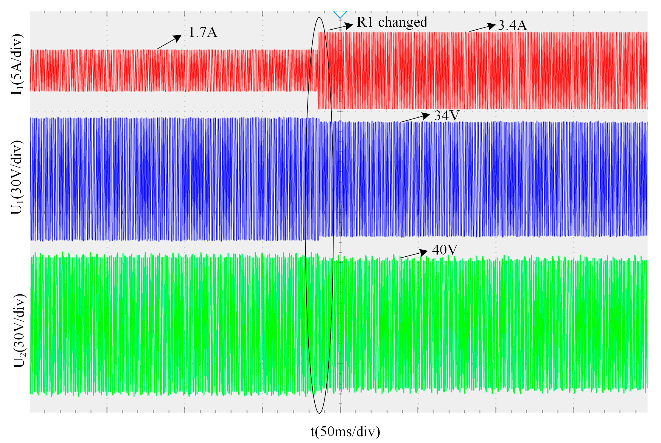
In the system, at one time, while maintaining Load 2 at a constant value of 20 Ω, Load 1 is switched from 20 Ω to 10 Ω. The corresponding voltage and current waveforms of Load 1, along with the voltage waveform of Load 2, are shown in
Figure 18. The blue and red curves represent the voltage and current of Load 1, respectively, while the green curve represents the voltage of Load 2.
As can be seen from
Figure 18, when Load 1 is switched at one time, Load 2’s voltage remains stable at 40 V, indicating that the switching of Load 1 has almost no effect on Load 2.
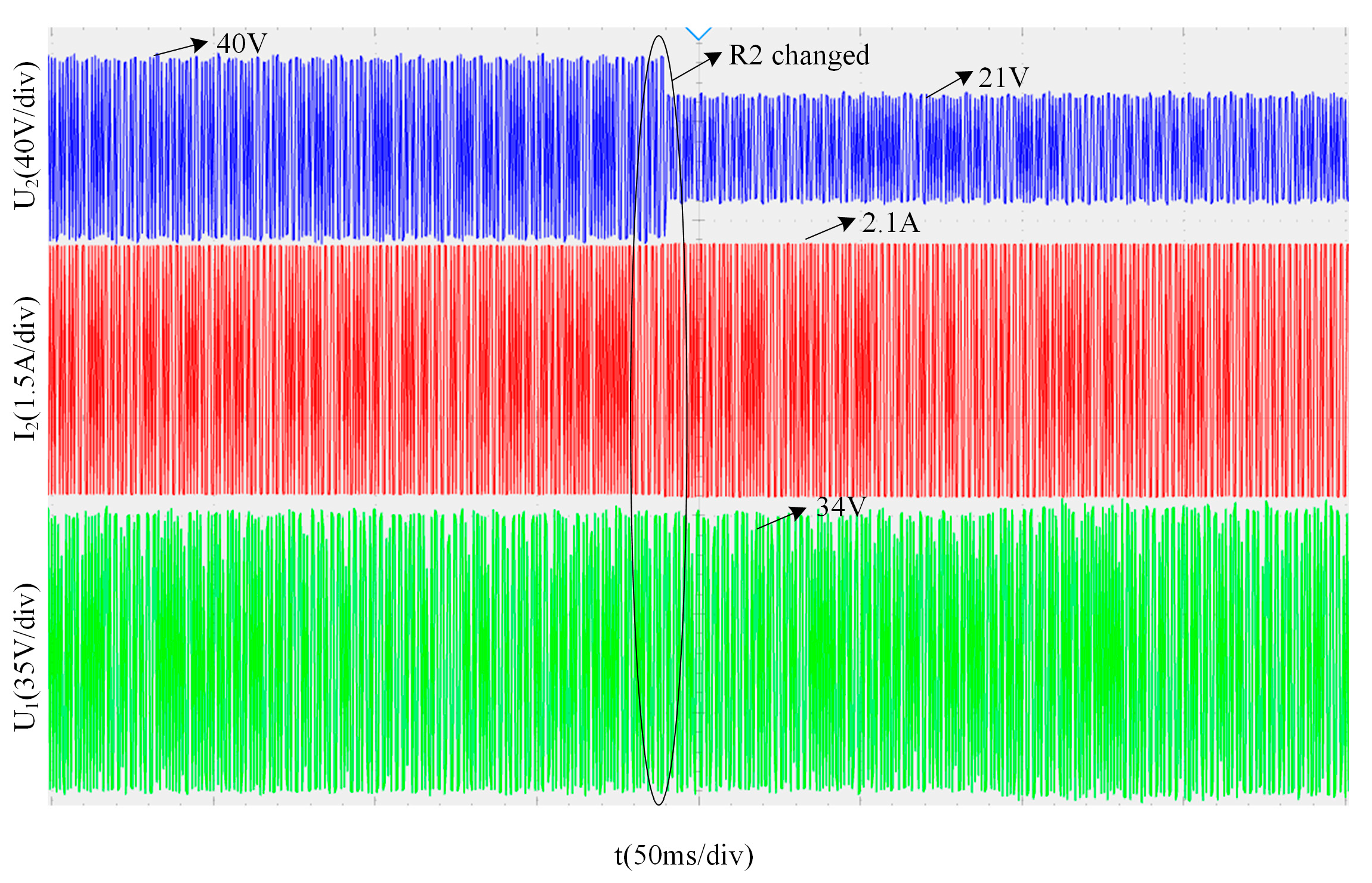
In the system, at another time, while maintaining Load 1 at a constant value of 20 Ω, Load 2 is switched from 20 Ω to 10 Ω. The corresponding voltage and current waveforms of Load 2, along with the voltage waveform of Load 2, are shown in
Figure 19. The blue and red curves represent the voltage and current of Load 2, respectively, while the green curve represents the voltage of Load 1.
As can be seen from
Figure 19, when Load 2 is switched at another time, Load 1’s voltage remains stable at 34 V, indicating that the switching of Load 1 has almost no effect on Load 2.
In summary, during operation, when the resistance value of one load branch is switched, the output power of the corresponding receiving circuit changes accordingly, while the output power of the other receiving circuit remains largely unaffected. This demonstrates that the load output power exhibits independence.
The experimental results have been compared with the existing literature, and the comparison results are shown in
Table 3. Different coil sizes allow different misalignment distances, and the ratio of the maximum misalignment distance to the coil side length can uniformly characterize the anti-misalignment capability of the magnetic coupling mechanism. The comparative analysis indicates that while the method analyzed in Reference [
21] lacks anti-rotation capability, it exhibits greater misalignment tolerance; the system discussed in Reference [
22] possesses anti-rotation capability with relatively good
CCRR (Coupling Coefficient under Rotation and misalignment) performance; the method proposed in this study achieves a higher
CCRR value, demonstrating superior anti-misalignment performance.
