Article

Genetic Algorithm-Based Energy Management Strategy for Fuel Cell Hybrid Electric Vehicles

Department of Automation, University of Science and Technology of China, Hefei 230027, China
*
Author to whom correspondence should be addressed.
World Electr. Veh. J. 2025, 16(8), 467; https://doi.org/10.3390/wevj16080467
Submission received: 2 July 2025 / Revised: 11 August 2025 / Accepted: 14 August 2025 / Published: 16 August 2025

Abstract

Enhancing system durability and fuel economy stands as a crucial factor in the energy management of fuel cell hybrid vehicles. This paper proposes an Equivalent Consumption Minimization Strategy (ECMS) based on the Genetic Algorithm (GA), aiming to minimize the overall operating cost of the system. First, this study establishes a dynamic model of the hydrogen–electric hybrid vehicle, a static input–output model of the hybrid power system, and an aging model. Next, a speed prediction method based on an Autoregressive Integrated Moving Average (ARIMA) model is designed. This method fits a predictive model by collecting historical speed data in real time, ensuring the robustness of speed prediction. Finally, based on the speed prediction results, an adaptive Equivalence Factor (EF) method using a GA is proposed. This method comprehensively considers fuel consumption and the economic costs associated with the aging of the hydrogen–electric hybrid system, forming a total operating cost function. The GA is then employed to dynamically search for the optimal EF within the cost function, optimizing the system’s economic performance while ensuring real-time feasibility. Simulation outcomes demonstrate that the proposed energy management strategy significantly enhances both the durability and fuel economy of the fuel cell hybrid vehicle.

1. Introduction

1.1. Research Background

With the continuous advancement of industrialization worldwide, humanity is experiencing not only social progress and development but also environmental challenges such as global warming and rising sea levels. Reducing greenhouse gas emissions and improving living conditions have become key concerns for many nations. In response, countries are actively exploring new energy sources to replace traditional fossil fuels. As an emerging energy source in the 21st century, hydrogen energy offers significant advantages, including high calorific value and zero pollution [1]. Among its various applications, proton exchange membrane fuel cells (PEMFCs) stand out due to their high energy efficiency, strong controllability, and broad application prospects [2,3]. These advantages make PEMFCs highly promising for use in transportation, residential energy supply, and other sectors.
Compared to traditional electric vehicles, fuel cell hybrid electric vehicles (FCHEVs) offer notable benefits in terms of refueling efficiency and driving range. However, fuel cell systems suffer from poor dynamic response capabilities, making it difficult to fully meet the demanding operational conditions of vehicular applications. To address this limitation, integrating auxiliary power sources such as lithium-ion batteries has become a necessary solution. Auxiliary batteries can provide a fast response and high power output, effectively compensating for the transient response delay of fuel cells. However, the effective coordination of multiple power sources remains a critical challenge for FCHEVs. As a result, research on energy management strategies for FCHEVs has become essential. A well-designed energy management strategy (EMS) can ensure efficient synergy between fuel cells and other energy systems, such as batteries or supercapacitors, thereby enhancing overall system efficiency and improving vehicle dynamic performance.

1.2. Literature Review

For the energy management of FCHEVs, strategies can be categorized into rule-based EMSs [4], optimization-based strategies [5], and learning-based strategies.
Rule-based EMS (RB-EMS) allocate power between the fuel cell and the power battery through pre-defined logic and rules. Typically, this strategy requires the design of a rule table based on the researcher’s expertise, experimental results, or mathematical models [6]. Power distribution between the fuel cell and the battery is then determined by referencing the rule table according to the vehicle’s current state and input parameters. Generally, such EMSs are straightforward to implement, require minimal computational effort, and do not necessitate considering the vehicle’s working conditions. These advantages render RB-EMSs widely applicable in real vehicle scenarios. Wang et al. [7] devised a finite state machine-based EMS that partitions the state of charge (SOC) and input–output of lithium-ion batteries into nine distinct states, effectively managing hybrid power systems. This study also explored energy management following the integration of supercapacitors. Yuan et al. [8] addressed the issue where the energy generated by the fuel cell lags behind the power demand within certain ranges. They implemented a dynamically allocated, optimized power-following logic threshold filtering strategy, which reduced hydrogen consumption and effectively stabilized the battery’s capacity range. RB-EMSs offer simplicity and strong real-time performance, ensuring stable and reliable system operation. However, such strategies are also limited by poor flexibility and suboptimal performance [9]. Some scholars employed fuzzy control rules [10] to tackle such issues. Some scholars [11] compared deterministic rule-based and fuzzy logic energy management strategies for PEMFC hybrid vehicles, demonstrating their respective strengths in computational efficiency and adaptability to improve overall energy efficiency under standard driving cycles. Nevertheless, RB-EMS performance heavily relies on parameter calibration, often making it challenging to optimize for fuel economy.
Optimization-based energy management strategies represent advanced methods that dynamically allocate power output across different energy sources. These strategies primarily include two types of solutions: global optimization (e.g., Dynamic Programming (DP) [12]) and local optimization (e.g., Model Predictive Control (MPC) [13] and ECMS [14,15]). Global optimization strategies employ algorithms that can find the optimal solution on a global scale. Ravey et al. [16] designed an EMS using the SOC of the battery as the state variable in a DP framework, improving the vehicle’s overall economic performance. To explore the potential of achieving online optimal energy management, scholars have investigated numerous suboptimal EMSs. These include the MPC and ECMS. MPC first formulates a mathematical model based on the vehicle’s operating state, which can predict the dynamic behavior of the system over a future time horizon, such as vehicle speed and power requirements [17]. By incorporating constraints like power limits and SOC ranges, MPC then employs optimization algorithms to solve for the minimization of the objective in real time, thereby determining the energy distribution strategy. Zhou et al. [18,19] proposed a cooperative speed prediction method based on Markov chains and Fuzzy C-Means clustering, which enhances prediction accuracy. Similarly, Yang et al. [20] derived an optimal power distribution decision by minimizing a multi-objective function. Jia et al. [21] developed a system Linear Parameter Variation (LPV) prediction model that considers changes in system parameters. The LPV prediction model is updated online to adapt to changes in battery charging status. Since the precision of MPC is closely tied to the accuracy of its predictions, researchers have primarily focused on improving prediction accuracy. In addition to using conventional or improved Markov chains [22] for prediction, some have explored the use of neural networks [23] and other nonlinear models to forecast vehicle speed. Although these speed prediction methods have demonstrated high accuracy in simulation environments, their performance heavily relies on the completeness of historical databases [24]. Lin et al. [25] developed a Pontryagin’s Minimum Principle (PMP)-based predictive energy management strategy for FCPHEVs that derives and corrects co-state boundaries in real time to enable fast, optimal, and constraint-compliant control. Moreover, Ma et al. [26] proposed a variable-horizon velocity prediction-based adaptive PMP-EMS for FCHEVs. In real-world conditions, vehicle speed is influenced by numerous uncertain factors, such as the random distribution of traffic lights and adverse weather conditions like rain or snow. Therefore, some scholars [27] proposed an energy management strategy that incorporates future terrain information to optimize power allocation, improving battery durability and reducing operating costs.
ECMSs aim to minimize the overall energy consumption of the system [28]. For electrical energy consumed by the battery, ECMSs employ an EF to convert it into an equivalent fuel consumption [29]. This EF is crucial, as it significantly influences battery output and, in turn, the overall energy distribution. Therefore, much of the research in this area has focused on determining the optimal EF. A conventional approach involves offline optimization to find the EF for specific operating conditions [30]. However, discrepancies often arise between the practical driving cycle and the specific conditions used in offline training, resulting in suboptimal energy allocation policies. To address this limitation, Wei et al. [31] proposed a feedback regulation method based on the current SOC of the lithium-ion battery, dynamically adjusting the EF based on the discrepancy between the current SOC and the reference SOC. Li et al. [32] proposed a method for the adaptive adjustment of the EF based on vehicle driving conditions. This method involves offline training to derive the optimal EF values for different driving conditions. During the online application process, the current driving conditions are first determined, and then the corresponding EF values are applied in real time. Despite these advancements, previous methods primarily focused on hydrogen consumption as a single optimization objective, neglecting economic losses due to aging fuel cells and lithium-ion batteries [33]. Therefore, Li et al. [34,35] proposed an adaptive ECMS considering both hydrogen consumption and fuel cell degradation, bridging the gap between fuel cell lifetime degradation and adaptive ECMS. In summary, ECMS improves fuel economy and energy utilization efficiency through real-time optimization algorithms. Gao et al. [36] presented a scenario-oriented adaptive ECMS using NODC-based EF initialization and hybrid neural network speed prediction to enhance SOC control and reduce hydrogen consumption in fuel cell hybrid vehicles. Nevertheless, challenges remain in enhancing the adaptability of the EF and in holistically considering the effects of fuel cell and lithium-ion battery aging on economic performance, which warrant further research. This article proposes an EMS for searching for the best EF in real time, which effectively avoids the situation where EF is not applicable due to the particularity of offline working conditions. Moreover, this article also fully considers the impact of fuel cell aging and power cell aging.
The application of learning-based strategies in fuel cell hybrid systems has demonstrated significant potential. By leveraging machine learning and artificial intelligence techniques, these strategies can optimize energy management while exhibiting strong adaptability and intelligence, especially in handling complex nonlinear problems and uncertainties [37]. In fuel cell hybrid systems, learning-based strategies first collect a large amount of operational data from various sensors and historical records. This data is then processed and used to train machine learning models, with commonly used models including neural networks [38], support vector machines [39], and Reinforcement Learning (RL) [40]. Unlike EMSs based on neural networks, reinforcement learning-based strategies directly learn the optimal energy management scheme from historical data [41]. Through continuous experimentation and feedback, the agent gradually optimizes its control strategies, with RL algorithms playing a critical role in this process. Currently, RL algorithms commonly used in energy management include Q-learning [41], deep Q-network [42], deep deterministic policy gradient [43], and Twin Delayed Deep Deterministic Policy Gradient (TD3) [44]. Zhou et al. [45] applied deep reinforcement learning algorithms to design SOC regulators, which assist in power distribution among various energy sources. Liu et al. [46] proposed an adversarial imitation reinforcement learning EMS, using DP-based expert guidance to accelerate training and reduce battery capacity loss. In further studies, Deng et al. [47] applied TD3 to the energy management of FCHEVs, showing promising performance. Nie et al. [48] proposed a hierarchical cooperative optimization strategy combining TD3 and other energy management techniques to reduce hydrogen consumption. Li et al. [49] applied a proximal-policy-optimization-based deep reinforcement learning EMS for FCHVs. However, these strategies also face several challenges. For instance, training and optimizing the models require a large amount of high-quality data, and the computational demands during real-time operation are significant. Furthermore, the performance and stability of these models in real-world complex environments require further validation and optimization [50]. While learning-based and deep reinforcement learning methods offer promising results, they are often limited by high data requirements and poor real-time adaptability. Thus, there remains a gap in developing a lightweight, real-time EMS that balances prediction simplicity and optimization robustness. Essoufi et al. [11] proposed a data-driven co-state network energy management scheme for fuel cell and battery electric vehicles that ensures robust, constraint-compliant control without prior system knowledge or extensive training.
Despite the significant progress made in EMSs for FCHEVs, most existing studies tend to focus either on enhancing fuel economy or improving power response, while few simultaneously address the combined impact of fuel cell and battery aging on long-term economic performance [51]. This study introduces an EMS framework that combines ARIMA-based real-time speed prediction with GA-based equivalent factor (EF) optimization. This framework is designed to not only maintain system responsiveness and predictive stability under uncertain traffic conditions but also to holistically optimize fuel consumption and aging-related economic losses.

1.3. Original Contributions

Compared with deep learning models such as RNN and LSTM, which require extensive offline training, the ARIMA model offers low computational complexity and eliminates the need for prolonged training, making it well suited for real-time vehicle speed prediction under limited onboard computational resources. Furthermore, ARIMA provides interpretable parameters and robust short-term temporal modeling capabilities, enabling stable performance in dynamic and uncertain traffic environments.
For optimization, the Genetic Algorithm (GA) is adopted over methods such as Particle Swarm Optimization (PSO) and Reinforcement Learning (RL) due to its global search capability, implementation simplicity, and flexibility in handling nonlinear multi-objective functions involving both fuel consumption and degradation-related economic costs. Unlike RL, which requires large-scale interaction data and offline simulation environments, GA can operate in online or semi-online modes with relatively low computational overheads.
The main contributions of this work are summarized as follows:
(1) A lightweight ARIMA-based real-time vehicle speed prediction framework is proposed, employing a sliding time window for dynamic updates. This design achieves a balance between predictive accuracy and computational efficiency, particularly in data-sparse scenarios.
(2) A novel GA-based adaptive equivalent factor optimization method is developed, integrating hydrogen fuel consumption with the economic costs of fuel cell and battery degradation. This approach bridges short-term energy optimization with long-term cost-effectiveness, enhancing both energy efficiency and system durability.
Overall, this study establishes a real-time, computationally feasible energy management framework that achieves a balance between predictive performance, optimization robustness, and lifecycle economic considerations.

2. System Topology and Modeling

In this study, the fuel cell data as well as the battery data in the FCHEV used were provided by the manufacturer. The entire FCHEV powertrain mainly consists of the fuel cell and its auxiliary system, the lithium-ion battery pack, the DC/DC converter, and the electric motor, and the FCHEV is shown in Figure 1. The following mainly introduces the component models related to energy management in the vehicle.

2.1. FCHEV Powertrain Topology

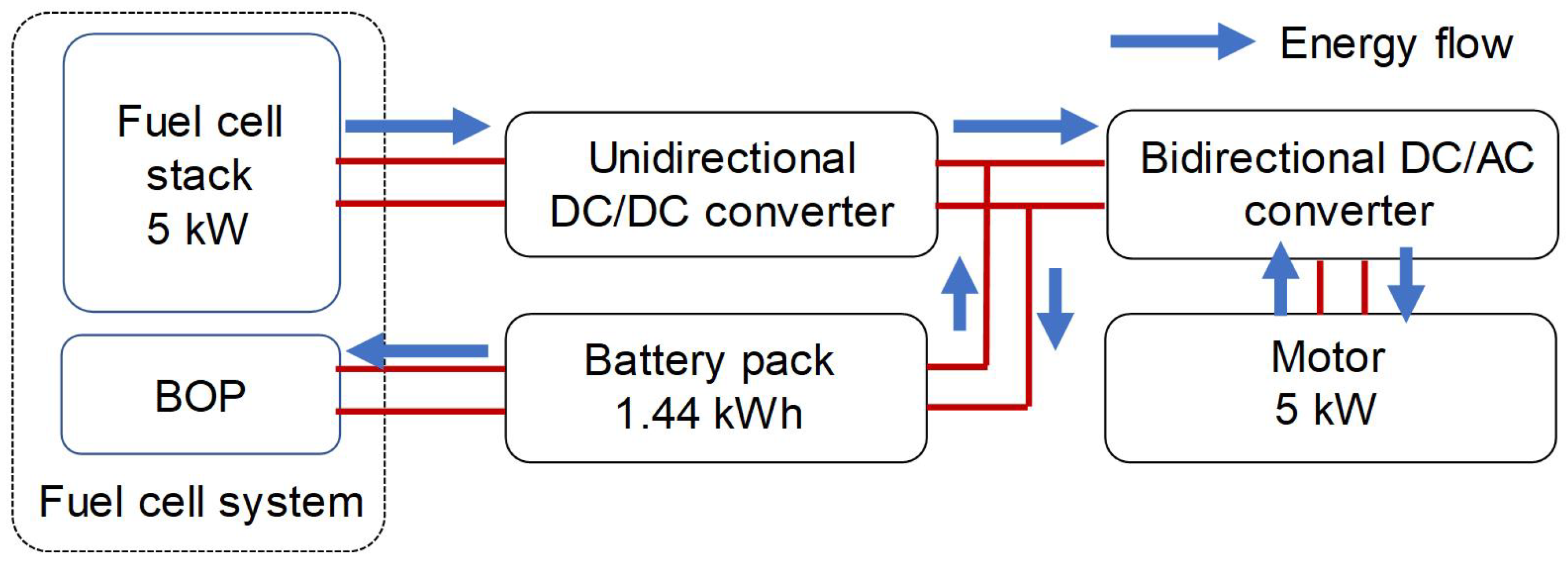
In FCHEVs, to ensure efficient energy management and stable system operation, the fuel cell and battery pack are connected to the bus through different types of DC/DC and DC/AC converter, each playing a critical role. The overall powertrain topology is illustrated in Figure 2.
First, the fuel cell is connected to the bus via a unidirectional DC/DC converter. The battery pack is directly connected in parallel to the bus, supplying power to the electric motor and other onboard systems. The bus is further linked to the electric motor through a bidirectional DC/AC converter. This converter serves two essential functions: it converts the DC power from the bus into AC power suitable for driving the motor and, during braking, converts the AC power generated by the motor back into DC power. This recovered energy is then fed back into the bus, enabling battery recharging and improving overall energy efficiency.

2.2. Model of the Vehicle

The parameters of the vehicle are shown in the Table 1, which can be used to calculate the demanded power based on the speed. The calculation formula is as follows:
F v = M g sin θ + μ M g cos θ + 0.5 ρ a i r A C a i r v 2 + δ M · d v d t
where μ is the coefficient of friction, g is the acceleration of gravity, θ is the slope of the road, and v is the speed. The required power P r of the whole vehicle and the required power P b u s , d e m of the bus can be calculated according to the following equations:
P r = F v · v
P bus , dem = P r η d c , P r 0 η d c P r , P r < 0
where η d c is the efficiency of the DC/DC converter. In this article, we assume that the efficiency of the DC/DC converter is a fixed value of 95%. In addition, we also assume that the transmission efficiency of the motor is 85%.

2.3. Model of Battery

In the EMS presented in this paper, the SOC of the power battery has a significant impact on energy distribution. Furthermore, this paper fully considers the economic implications associated with battery degradation. Therefore, our subsequent focus will be on modeling the SOC and health status of the battery.
The battery model uses an equivalent circuit model with a single internal resistance. Its output voltage U b and current I b can be calculated using the following equations:
U b ( t ) = U o c ( S O C , t ) I b ( t ) R b
I b = U o c ( S O C , t ) U o c 2 ( S O C , t ) 4 P b · R b 2 · R b
The battery cell is 2.5 Ah. Forty-four individual cells are connected in series to form a battery module, and four such modules are then connected in parallel to constitute the complete battery pack. Assuming that the external and internal characteristics of all batteries are consistent. Detailed specifications of the battery pack are presented in Table 2.
The battery S O C can be calculated using the following equations:
S O C ( t ) = S O C 0 1 Q b 0 t I b ( τ ) d τ
S O ˙ C ( t ) = I b ( t ) Q b
where S O C 0 is the initial cell S O C and Q b is the capacity of the cell.
Battery capacity degradation models are commonly classified into three categories: (1) electrochemical models; (2) empirical models based on experience; and (3) data-driven models. This paper employs an empirical model known for its relatively lower computational complexity. Widely adopted in the energy management strategies of electric vehicles [52], this model has attracted considerable attention. Typically, with an increase in the number of charging and discharging cycles, the battery capacity gradually diminishes. When the battery capacity drops by 20% compared to its initial value, it is deemed to have reached the end of its service life. Bloom et al. [53] proposed that, under constant operating conditions, the loss in capacity Δ Q ( % ) concerning the initial capacity can be estimated by the following equations:
Δ Q = B ( c ) · exp ( E a ( c ) R · T ) · A ( c ) z
E a ( c ) = 31700 370.3 · c ( J / mol )
z = 0.55
where Δ Q is the percentage of capacity loss in %, E a ( c ) is the activation energy, and c is the C-rate. B ( c ) is the pre-exponential factor as a function of the C-rate, as indicated in Table 3. R = 8.31 J/mol · K is the ideal gas constant, T c = 313 K (40 °C) is the lumped cell temperature, and z is the power-law factor. Under normal working conditions, the total throughput A ( c ) (in ampere-hour) is a function of the C-rate and working temperature. In this paper, in order to simplify the calculation, we assume that the temperature can be effectively controlled. A 20% capacity loss is considered as the end-of-life (EOL) of the battery, and the total discharged Ah throughput A s u m is, therefore, acquired by Equation (11).
A sum ( c , T c ) = 20 B ( c ) exp E a ( c ) R T c 1 / z
We defined N is the total number of cycles before end-of-life (EOL), which can be attained by
N = 3600 A s u m Q b
Similar to the S O C , we define the state-of-health ( S O H ) of the battery as 
S O H ( t ) = S O H 0 1 2 N Q b 0 t | I b ( τ ) | d τ
S O ˙ H ( t ) = | I b ( t ) | 2 N Q b
S O H 0 is the initial S O H . We define it as 1.

2.4. Model of PEMFC

The fuel cell system consists of a stack system and a balance of plant (BoP) system, and its output power can be calculated as follows:
P f c = P s t a c k P B o P
where P f c is the net output power of the fuel cell. P s t a c k is the output power of the fuel cell stack and P B o P is the power consumed by the auxiliary system. The hydrogen consumption rate can be expressed by the following equation:
m ˙ h 2 = N f c M H 2 2 F I f c
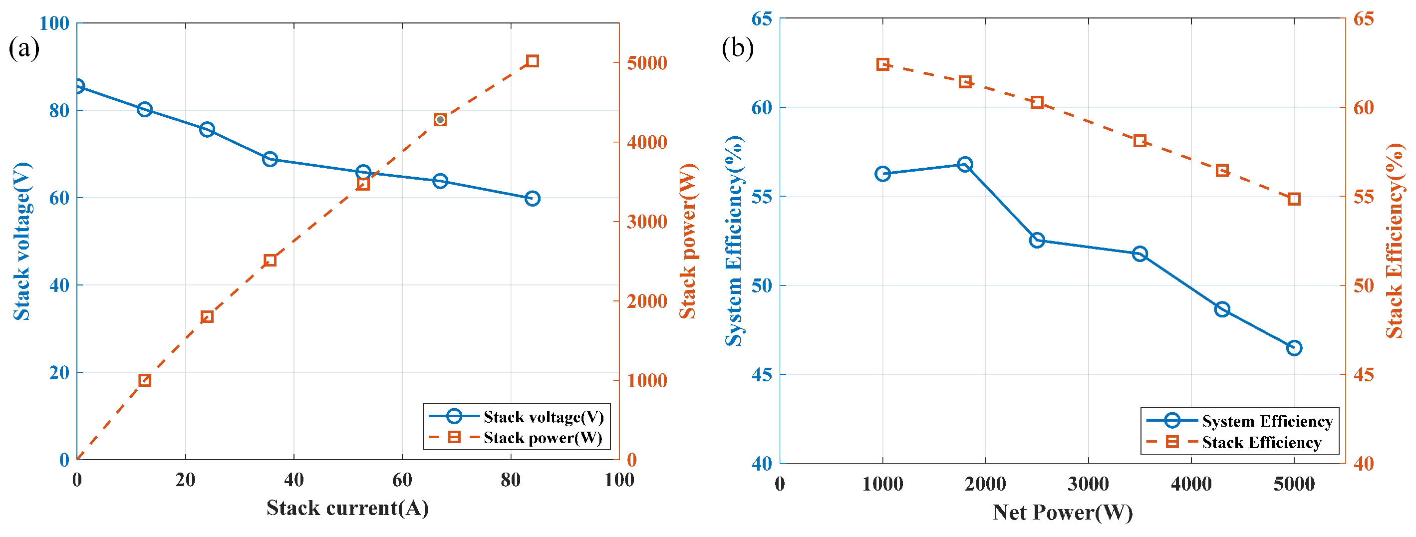
where M H 2 is the molar mass of hydrogen, N f c is the number of fuel cells, and F is the Faraday constant. The relationship between the net output power and net output current of the system, as well as the net output voltage and net output current, is shown in Figure 3a.
The efficiency of a fuel cell is defined as follows:
η f c = P s t a c k P B O P m H 2 · L H V
where L H V = 120 MJ· kg 1 is the low heating value of hydrogen, from which the efficiency of the fuel cell can be obtained, as shown in Figure 3b.
The aging of fuel cells includes four aspects: load changing cycles, start–stop, high-power load condition, and idle condition. It is generally believed that fuel cells operating below 20% of rated power are in an idle state, while those operating above 80% of rated power are in a high power state [18]. From this, we can obtain the aging model of the car under various operating conditions [55].
D f c = D h i g h + D i d l e + D s t a r t s t o p + D c h a n g e = d 1 T h i g h + d 2 T i d l e + d 3 N s t a r t s t o p + d 4 P c h a n g e
where d 1 = 0.41 × 10 6   s 1 ,   d 2 = 0.6 × 10 6 s 1 , d 3 = 1.9 × 10 3 , d 4 = 0.3 × 10 5 kW 1 are the model parameters. T h i g h and T i d l e are the time when the fuel cells operate in the high-power condition and the idle condition. N s t a r t s t o p is the start–stop number of the fuel cell. P c h a n g e is the variation of the fuel cell output power.

3. ECMS Based on GA

The overall framework of the proposed GA-ECMS is illustrated in Figure 4. The method consists of three main stages: (1) Vehicle speed prediction—Future vehicle speed is forecast using historical driving data, providing a basis for anticipating power demand in the upcoming period. (2) Genetic algorithm-based optimization—Within the prediction horizon, GA is employed to search for the optimal equivalent factor (EF) or control objective that minimizes the cost function. (3) Energy coordination—The optimal EF is applied to compute the control output sequence, thereby allocating power between the fuel cell stack, lithium-ion battery, and supercapacitor.
In the allocation process, the fuel cell serves as the primary power source and is operated, whenever possible, within its high-efficiency region. The battery responds to short-term, high-power transients, buffering rapid load changes and enhancing regenerative braking energy recovery. According to the principle of objective function minimization, the optimal power outputs of the fuel cell and the traction battery are calculated under the constraints of power demand, component state of charge, and operational conditions. The core of the algorithm relies on an optimization function that calculates the optimal power output of both the fuel cell and the battery. By dynamically adjusting their respective outputs, the strategy ensures efficient energy distribution under varying driving conditions.

3.1. Autoregressive Integrated Moving Average Speed Prediction

Traditional vehicle speed prediction algorithms typically require a large amount of offline data for pre-training to achieve accurate speed forecasts [56]. However, since vehicle speeds vary significantly under different road conditions, many researchers have improved prediction accuracy by categorizing driving speeds into several standard driving conditions. Separate speed prediction models are then trained using driving data corresponding to each condition, and the appropriate model is selected based on the vehicle’s current driving condition. Although this approach can enhance prediction accuracy to some extent, it relies on precisely determining the current driving condition before making predictions. Due to factors such as driver behavior and specific road conditions, actual driving conditions may deviate from the predefined standards, significantly reducing the accuracy of speed prediction. To overcome this challenge, the algorithm proposed in this paper employs a sliding window approach to fit a predictive model using real-time driving information, eliminating the need for predefined conditions and offline training. By doing so, the algorithm adapts to the unique driving cycles of individual vehicles while improving prediction accuracy, regardless of deviations from standard conditions.
This paper uses a classical forecasting model ARIMA for time series data, which has the advantages of robustness, broad applicability, a relatively simple model, and small computational volume. It combines autoregressive and moving average models with differential integration. The model describes a combination of autoregression and moving averages with the following mathematical model [57]:
y t = μ + i = 1 p r i y t i + ϵ t + i = 1 q θ i ϵ t i
Here, y t represents the predicted vehicle speed at time t, μ is the mean term, r i represents the autoregressive coefficients reflecting the influence of p past observations, θ i represents the moving average coefficients capturing the influence of q past forecast errors, and  ϵ t denotes the white noise error term. Therefore, the ARIMA model is denoted by (p, d, q). Figure 5 illustrates the framework of the proposed ARIMA algorithm for short-term speed prediction. The modeling process of ARIMA model usually includes the following steps:
Smoothness test: Differencing is applied to remove trends and cyclic patterns, ensuring that the statistical properties of the sequence remain constant over time, which is a prerequisite for ARIMA modeling. We perform a first-order difference on the vehicle speed sequence to obtain the acceleration sequence of the vehicle and prove that the vehicle acceleration sequence is a stationary sequence. A time series is a stationary sequence if and only if it satisfies the following two conditions:
(1) Finite Second Moment: This means that the variance of the sequence is finite, as shown in the following equation:
E ( X t 2 ) <
where X t represents the value of the sequence at time t. Obviously, the acceleration of any car is within a certain range ( a min a t a max ). Therefore, it is evident that the acceleration sequence satisfies Equation (20).
(2) Strict Stationarity: A time series X t , if the joint distribution of the sequence satisfies the following conditions for any t.
Mean invariance:
E ( X t ) = μ
For all t, the mean of the sequence remains unchanged over time. For the complete driving conditions of the vehicle (from vehicle start to vehicle stop at the end of the journey), the speed change of the vehicle is 0. That is, the cumulative sum of accelerations throughout the entire process is 0. Therefore, E ( a t ) = 0 , which satisfies Equation (21).
Covariance invariance: For any t and s, as well as any positive integer k, the following equation is satisfied:
Cov ( X t , X t + k ) = Cov ( X s , X s + k )
The sequence is considered strictly stable. For the same vehicle, it is obvious that we can assume that the acceleration of the vehicle at different times is independent and identically distributed, which satisfies the following equation:
E [ X Y ] = E [ X ] E [ Y ]
For any two different moments of acceleration a t and a t + k ,
C O V ( a t , a t + k ) = E ( a t E [ a t ] ) ( a t + k E [ a t + k ] ) = E [ a t a t + k ] E [ a t ] E [ a t + k ]
According to Equation (23), we can deduce that C O V ( a t , a t + k ) = 0 . Based on the above analysis, it can be proven that the acceleration of a vehicle within a driving cycle is a stable random sequence. It can meet ARIMA’s requirements for predicting data stationarity.
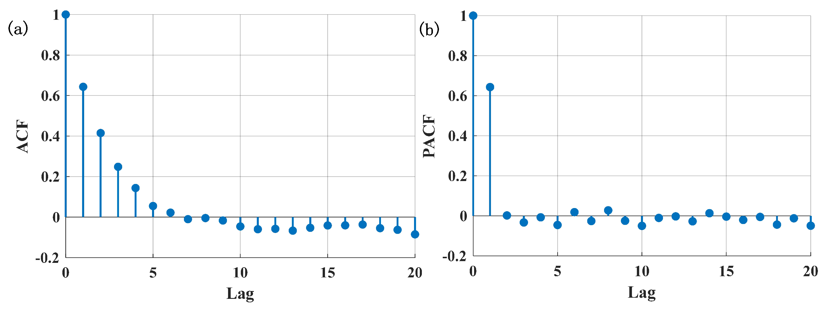
Choosing ARIMA order: Proper selection of the order parameters p and q in the ARMA model ensures optimal model performance. The autocorrelation function (ACF) and partial autocorrelation function (PACF) reveal repetitive patterns within a time series and assist in determining the appropriate order of the ARMA model.
The ACF measures the correlation between a time series and its own past values. For a given time series y t ( t = 1 , 2 , , m ), the ACF is calculated as follows:
ρ n = 1 m n t = n + 1 m ( y t y ¯ ) ( y t n y ¯ ) 1 m t = 1 m ( y t y ¯ ) 1 m n t = n + 1 m ( y t n y ¯ )
where n represents the lag factor and  y ¯ denotes the mean of the time series y t .
The PACF, on the other hand, measures the linear dependency of a time series on its past values, eliminating the influence of intermediate lags. The PACF is defined as
y ˜ t = y t y ¯ = t = 1 n ψ t , n y ˜ t 1 + ϵ t
where the last coefficient ψ n , n represents the partial autocorrelation coefficient corresponding to lag n.
Figure 6a,b illustrate the ACF and PACF of the velocity profile observed in real-world driving conditions. Based on the analysis of the ACF and PACF plots in Figure 6, the optimal values of p and q for the model are determined to be 3 and 2, respectively.
Fitting the ARIMA model: We utilized a sliding window of vehicle speed data to fit the model, with a maximum window time of 200 s. If the time frame is less than 200 s, the window encompasses all available vehicle speed data. The ARIMA predictor is employed to forecast vehicle speed for the next 20 s. The maximum window size was determined through offline training, as shown in Table 4. When the sliding window exceeded 200 s, the fitting time increased significantly, and the corresponding prediction accuracy improved. However, the improvement in accuracy was marginal, leading us to select 200 s as the optimal maximum window size.
Forecasting: The fitted ARIMA model is utilized to forecast future moments.

3.2. ECMS Formulation

In the traditional strategy, researchers often only aim to minimize the hydrogen consumption. In this paper, we add the losses caused by fuel cell aging and battery capacity degradation. In order to minimize the total operating costs of the FCHEV over each prediction horizon T h , using price as a medium to relate these costs, the objective function J can be defined as
m i n J j = C H 2 , j + C f c _ d e g r , j + C b a t , j + D s o c , j
where j is every sampling point within the prediction domain.
(1) C H 2 is the hydrogen cost.
C H 2 , j = G H 2 · m H 2 , j = G H 2 · ( m H 2 , f c , j + λ · I b , j Q b )
where G H 2 is the hydrogen price per kg, set at USD 4 [58]. m H 2 is the hydrogen consumption of the fuel cell, and  λ · I b , j Q b is the equivalent hydrogen consumption of battery pack output power.
(2) The PEMFCs degradation cost C f c , j is computed by
C f c _ d e g r , j = k · G f c · D f c , j
where G f c is the price of PEMFC, set at USD 14,000, constituting 20% of the total vehicle cost. To ensure that the power of fuel cells can be freely switched, the cost of fuel cell aging needs to be multiplied by a coefficient k.
(3) The battery degradation cost C b a t , j is calculated by
C b a t _ d e g r , j = G b a t · S O ˙ H j
where G b a t is the price of the battery, which is USD 360.
(4) D s o c is a deliberate penalty term to make the battery as charge-sustaining as possible.
D s o c , j = a · ( S O C ( t ) S O C r e f ) 2
where a is a penalty coefficient. The following constraints need to be satisfied in order to ensure the safe operation of the system.
P b ( t ) = P b u s ( t ) P f c ( t ) · η d c S O C min < S O C ( t ) < S O C max P fc , min < P fc ( t ) < P fc , max P b , m i n < P b ( t ) < P b , m a x
In Equation (27), we choose P f c ( t ) as the control variable and S O C ( t ) as the state variable. According to Equations (5), (7) and (32), the relationship between battery S O C ( t ) and P f c ( t ) can be rewritten as
S O ˙ C ( t ) = f ( S O C ( t ) , P f c ( t ) )
Then, Formula (27) can be written as
min J j = G H 2 · m H 2 , j ( P f c ( t ) ) + λ f ( S O C ( t ) , P f c ( t ) ) + C f c _ d e g r , j ( P f c ( t ) ) + C b a t , j ( S O C ( t ) , P f c ( t ) ) + D s o c , j ( S O C ( t ) , P f c ( t ) )
where λ is the EF. For a given EF, the optimal control quantity [ P f c * (j), …, P f c * (j + T h − 1)] is obtained by solving Equation (27) at each moment to minimize the instantaneous cost, and the optimal control is substituted into the state Equation (6) to obtain the optimal update of the S O C ( t ) . Thus, the value of λ affects the [ P f c * (j), …, P f c * (j + T h 1 ) ] and also affects the updating of [ S O C * (j), …, S O C * (j + T h 1 ) ] . The objective of the ECMS is to obtain the optimal P f c net that can minimize the total cost m i n J in the predicting horizon. We can obtain the total cost by adding up all the previous minimum values.
J t o t a l = j = 0 T h m i n J j

3.3. GA to Find the Optimal EF

To achieve real-time optimization of the EF, GA is employed to search for the optimal EF within the prediction horizon. The key steps of the GA are as follows.
(1) Fitness Evaluation Formula: In the GA, each individual (solution) is evaluated based on an objective function, where a lower function value indicates a higher fitness. The objective function in this study represents the minimum loss within the prediction domain, (detailed in Equation (27)), denoted as
f ( λ , v s e q u e n c e ) = J t o t a l
The fitness value H ( λ ) is calculated as
H ( λ ) = 1 f ( λ , v s e q u e n c e )
where f ( λ , v s e q u e n c e ) represents the objective function value of individual λ within the prediction domain, reflecting the overall loss incurred during vehicle operation. A larger H ( λ ) indicates a superior individual in the current generation.
(2) Roulette Wheel Selection: Roulette wheel selection is a fitness-proportionate selection method, where the probability of an individual being chosen is proportional to its fitness value. Given a population of N p individuals with fitness values H 1 , H 2 , , H N p , the probability of selecting individual i is given by
P i = H i i = 1 N p H i
This selection method ensures that individuals with higher fitness have a greater chance of being chosen, thereby accelerating the propagation of superior solutions.
(3) Crossover Operation: Crossover is a critical operation in GA that generates offspring by exchanging genetic information between parent individuals. Suppose the genes of two parent individuals are represented as
λ 1 = [ λ 1 , 1 , λ 1 , 2 , ] , λ 2 = [ λ 2 , 1 , λ 2 , 2 , ]
The offspring gene after crossover can be expressed as
λ c h i l d = [ λ 1 , 1 , λ 1 , 2 , , λ 2 , k , ]
where λ 1 , 1 , λ 1 , 2 , are gene segments inherited from Parent 1, while λ 2 , k , are from Parent 2. The purpose of crossover is to combine the advantageous traits of both parents to generate potentially superior solutions. For a given pair of parents λ p and λ q , this study employs linear recombination to generate offspring λ i , j as follows:
λ i , j = α λ p + ( 1 α ) λ q
where α is a random value between 0 and 1.
(4) Mutation Operation: Mutation introduces genetic diversity by randomly altering an individual’s gene values. Given an individual λ = [ λ 1 , λ 2 , ] , mutation modifies one of its genes to a new value λ i , yielding a mutated individual:
λ = [ λ 1 , λ 2 , , λ i , ]
Mutation prevents the algorithm from getting trapped in local optima and helps maintain population diversity. To enhance diversity, this study applies zero-mean Gaussian perturbation to selected offspring λ i , ensuring randomness in mutation:
λ i = λ i + N ( 0 , σ 2 )
where the standard deviation σ adapts over iterations:
σ ( t ) = σ 0 · e β t / T m a x
where σ 0 is the initial mutation intensity and  β is the decay coefficient.
(5) Termination Condition: The GA terminates under two common conditions: (1) reaching the maximum number of generations G m a x or (2) when the fitness improvement is negligible or a predefined convergence criterion is met. In this study, the algorithm terminates upon reaching the maximum evolution generations.
The process of using the GA to optimize the EF is summarized in Algorithm 1.
Algorithm 1: GA for Optimal EF Search
Wevj 16 00467 i001

4. Experiment and Results

This section will discuss the effectiveness of the GA-ECMS. First, the performance of the proposed speed predictor is analyzed. Subsequently, ECMS experiments are conducted based on real-world driving cycles. The results are then compared with those from the ECMS based on driving condition recognition and the RB-EMS.

4.1. Performance Analysis of the Speed Predictor

In order to check the performance of the speed predictor, a real FCHEV driving cycle in an industrial park was used, as shown in Figure 7a. The data sampling time is 1 s. The speed predictor’s performance is assessed using various statistical parameters, including the Root Mean Square Error (RMSE), the Mean Absolute Error (MAE), and the Tel Inequality Coefficient (TIC). These parameters evaluate the predictive accuracy by comparing predicted data (Pi) against experimental data (Ti). The RMSE and MAE quantify the numerical discrepancy between predicted and experimental data. TIC assesses the proximity between the predicted and actual time series, typically ranging between 0 and 1. Generally, a smaller TIC value indicates higher prediction accuracy.
R M S E = i = 1 n P i T i 2 n
M A E = 1 n i = 1 n P i T i
TIC = 1 n i = 1 n P i T i 2 1 n i = 1 n P i 2 + 1 n i = 1 n T i 2
As illustrated in Figure 7, the solid blue line represents the actual speed curve, while the dashed red line denotes the predicted speed curve. Initially, due to the limited amount of data available for model fitting, the prediction exhibits a noticeable deviation from the actual speed. However, as more data becomes available, the predicted speed trend gradually aligns with the actual speed trajectory, demonstrating improved accuracy over time.
From Table 5, it can be observed that as the prediction step size increases, the performance of the predictor gradually declines.
The focus of this study is a fuel cell sightseeing vehicle, in which the fuel cell operates at six fixed power levels to simplify control, resulting in significant power differences between these operating points. Consequently, the EMS is relatively insensitive to speed prediction accuracy, as moderate prediction errors do not influence the fuel cell’s output power. However, cumulative errors within the prediction horizon may lead to substantial deviations in the EF, ultimately affecting power distribution. Additionally, excessively short prediction horizons may cause the EMS to become trapped in local optima. Therefore, the prediction horizon must be carefully selected to balance accuracy and computational efficiency. Based on this analysis, a 20 s prediction horizon was chosen to minimize prediction errors while ensuring computational efficiency. In this study, the prediction horizon is set to 20 s to determine the optimal EF. The computed EF is then applied to control energy distribution for the subsequent 10 s, after which a new speed sequence for the next 20 s is predicted. This iterative process continues until the journey concludes.

4.2. Result Analysis

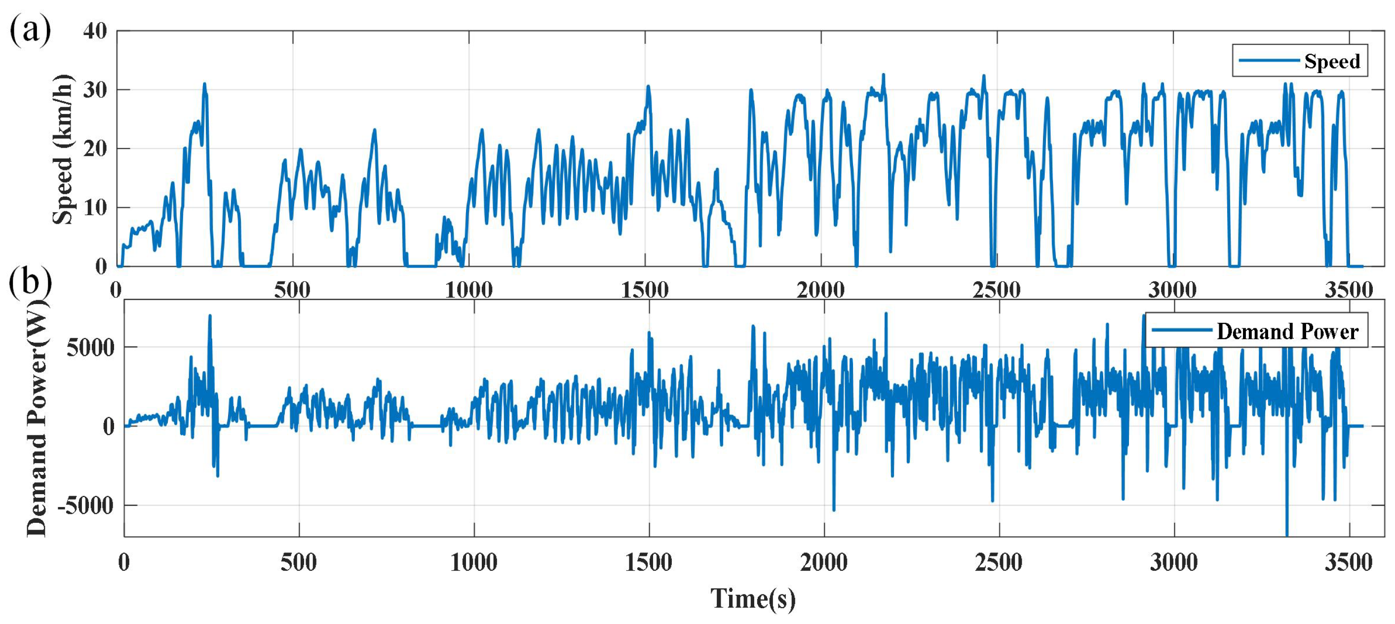
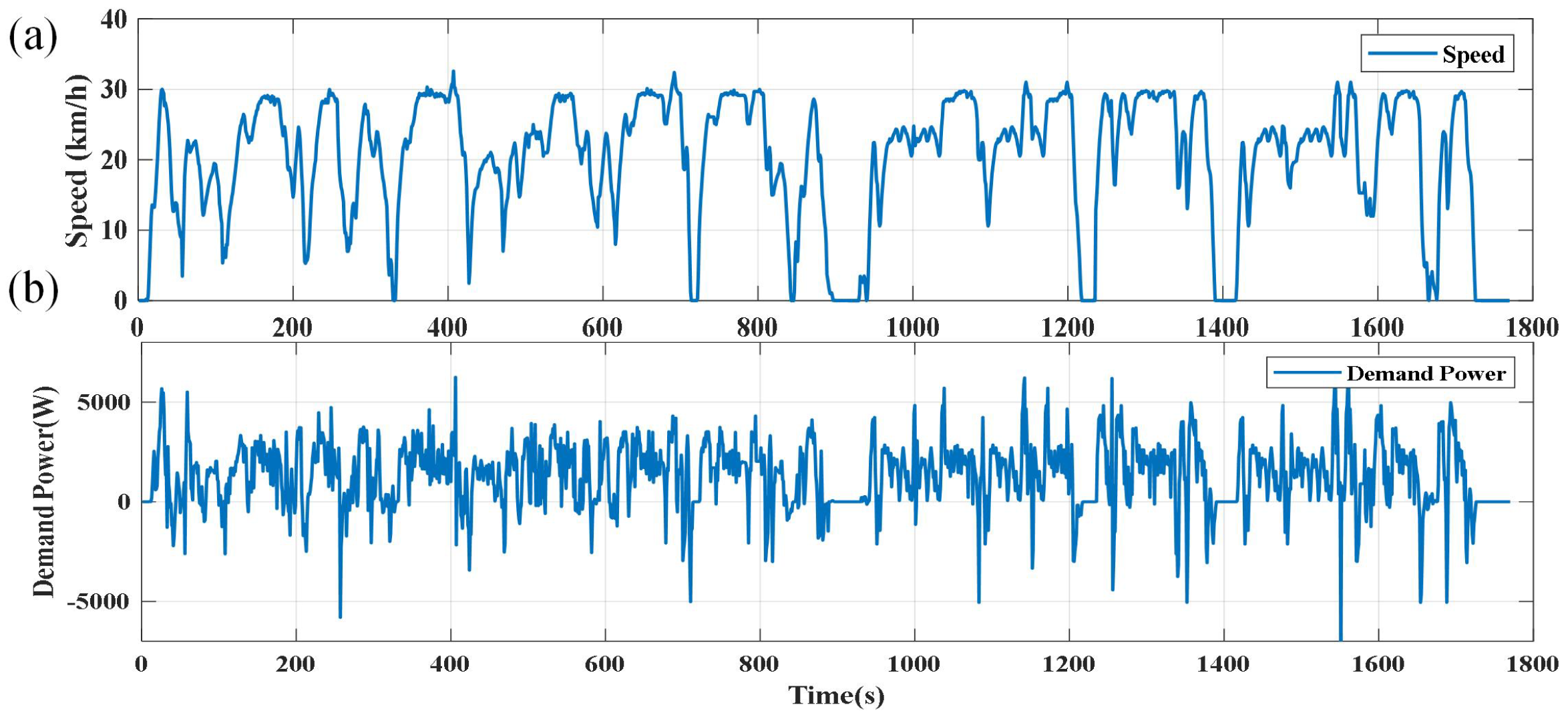
For the initial test conditions, the battery’s SOC is set to 0.7. The vehicle’s operating conditions consist of three distinct types. As shown in Figure 8a, the first condition, from 0 to 900 s, represents a low-speed congested scenario in an industrial park. From 900 s to 1800 s, the vehicle operates in a smooth, free-flowing condition, while from 1800 s to 3500 s, it experiences high-speed cruising. To comprehensively assess the performance of the EMS proposed in this paper, the focus will primarily be on evaluating its effectiveness under the industrial park driving conditions.
To provide a clear comparison, the simulation results of two commonly used energy management strategies will be compared with the GA-ECMS. These include the currently deployed RB-EMS in the vehicle and the traditional equivalent consumption minimization strategy (T-ECMS) based on operating condition identification. The key process of the RB-EMS is as follows:
  • When the SOC of the vehicle’s power battery pack falls below 0.6, the fuel cell starts up. Combined with the battery pack, it provides energy for the entire vehicle.
  • When the SOC of the vehicle’s power battery pack falls below 0.6, the fuel cell starts up. Combined with the battery pack, it provides energy for the entire vehicle. The output power of the fuel cells must not be lower than the current power demand of the entire vehicle, and any excess power is absorbed by the battery pack. If the power required by the vehicle exceeds the maximum power of the fuel cell, the fuel cell operates at its maximum power, and the remaining power is supplied by the battery pack.
  • When the SOC of the vehicle’s power battery pack falls below 0.6, the fuel cell starts up. Combined with the battery pack, it provides energy for the entire vehicle. When the SOC of the battery rises to 0.9, the fuel cell stops operating. The power required for the entire vehicle is then provided by the battery pack until the battery SOC drops below 0.6, at which point the process returns to step 1.
In general, the required power for the entire vehicle is within 5 kW, so the battery SOC tends to rise. Additionally, during fuel cell operation, the power output of the fuel cell will only increase and not decrease.
As illustrated in Figure 9, the proposed ECMS effectively maintains the fuel cell’s operation within a reasonable range, preventing aging caused by sustained high-power output. Compared to RB-EMS, the controlled power output of the fuel cell also reduces unnecessary battery degradation that would otherwise result from the continuous absorption of excess power during high-power operation. Traditional ECMS approaches require offline training to determine the optimal EF for specific driving conditions. During the offline training process, the battery’s initial SOC and final SOC are typically set to be equal. However, in real-world scenarios, discrepancies between the actual initial SOC, driving distance, and the values assumed in offline training often lead to suboptimal EF values that are not well suited to practical applications. Based on the actual operational results, it can be observed that the strategy proposed in this study demonstrates greater robustness compared to traditional ECMS based on driving condition recognition. It effectively minimizes unnecessary fluctuations in fuel cell power output, thereby improving the stability and efficiency of the energy management strategy.
Based on the data presented in Table 6 and Figure 10, the overall operating cost of different energy management strategies can be analyzed. The T-ECMS incurs a hydrogen consumption cost of USD 0.351, with fuel cell aging contributing USD 0.213 and battery aging accounting for USD 0.229. The RB-EMS results in a hydrogen consumption cost of USD 0.439, with fuel cell aging costs reaching USD 0.253 and battery aging costs amounting to USD 0.315. Notably, the economic losses due to system aging significantly exceed those caused by hydrogen consumption.
In contrast, the GA-ECMS exhibits the lowest aging-related costs while maintaining a competitive overall cost structure. Specifically, its hydrogen consumption cost is USD 0.345, while the economic losses from fuel cell aging and battery aging are reduced to USD 0.119 and USD 0.224, respectively. Importantly, a portion of the hydrogen consumption is converted into electrical energy and stored in the battery. To account for this, the converted portion is recalculated based on the international average electricity price, which is set at USD 0.1 per kilowatt-hour.
From Table 6 and Figure 10, it is evident that the GA-ECMS provides the most favorable economic outcomes. Over the course of a nearly one-hour-long simulation, the GA-ECMS demonstrated substantial cost savings. Compared to the RB-EMS, the overall economic loss was reduced by approximately 24.5%, while in comparison to the condition-based ECMS, the reduction was around 18.7%. These findings provide strong empirical support for the effectiveness of the GA-ECMS. Furthermore, Figure 11 illustrates that the fuel cell consistently operates at higher efficiency levels. Additionally, Figure 9c confirms that the GA-ECMS efficiently coordinates the power output of the fuel cell and battery, maintaining the SOC of the battery pack within a controlled fluctuation range.

4.3. EF Update Time Analysis

The update frequency of the EF proposed in this study is a critical aspect worth discussing. On one hand, frequent EF updates demand significant computational resources. This involves both the speed of velocity prediction and the efficiency of optimal solution computation, both of which must be executed rapidly. The research subject of this study, a fuel cell-powered sightseeing vehicle, has a fuel cell system designed to operate at only six fixed power levels to simplify control. There are substantial power differences between these operating points, making it unlikely that the optimal EF would shift between them frequently within short time intervals. Consequently, excessively frequent EF updates may not provide substantial benefits to the energy management strategy. On the other hand, excessively prolonging the EF update interval also presents drawbacks. Infrequent EF updates place higher demands on both the duration and accuracy of velocity predictions. Prediction errors tend to accumulate as the prediction horizon increases, leading to a significant discrepancy between the EF derived from predicted results and the actual driving conditions. Therefore, determining an appropriate EF update frequency is crucial. The following section of this paper examines the impact of different EF update intervals on the performance of the energy management strategy.
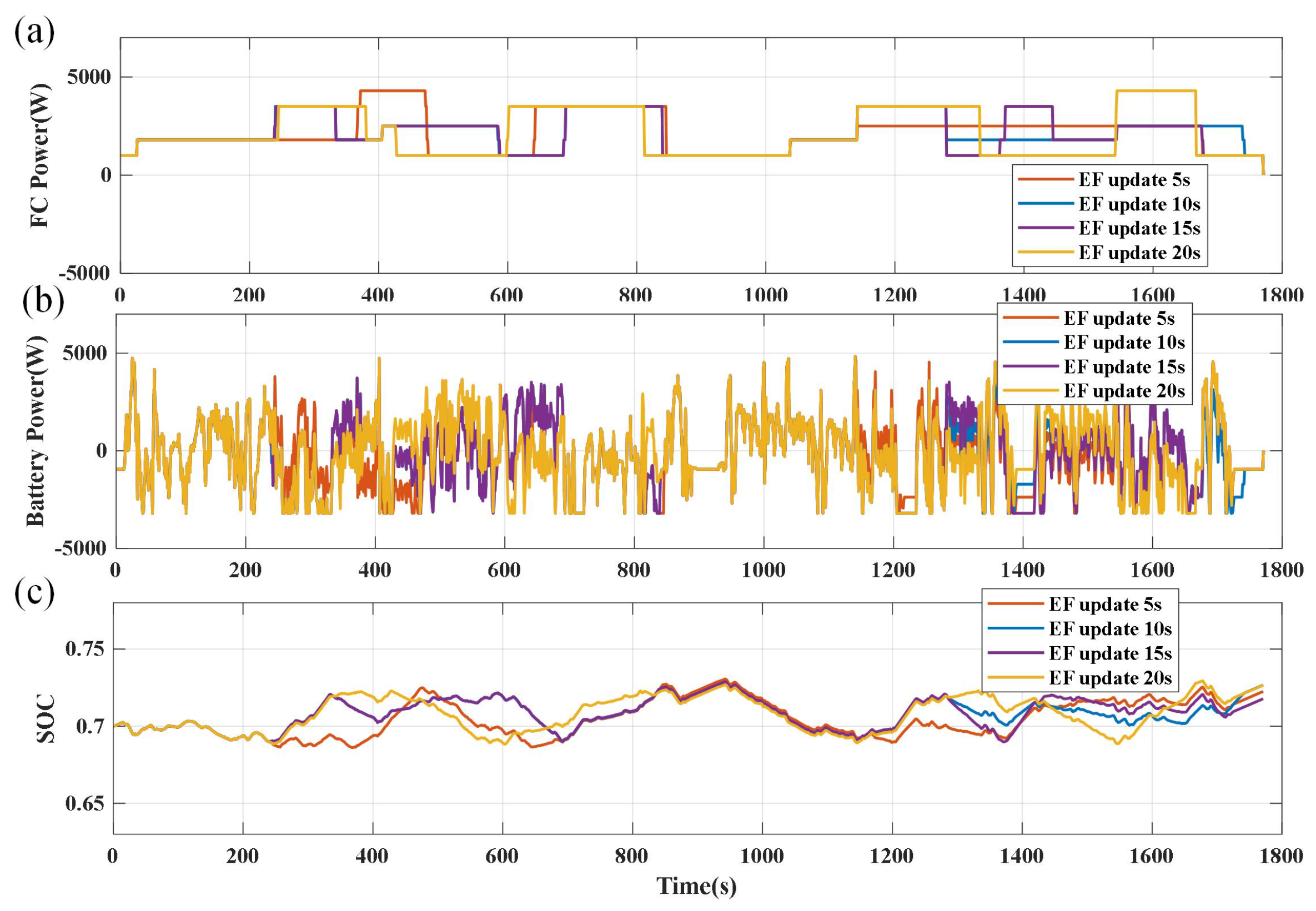
As shown in Figure 12a, the real-world driving conditions within an industrial park are still selected as the test driving scenario. Figure 12b illustrates the power output required from the fuel cell and battery systems to meet the vehicle’s driving demands. The energy distribution results for different EF update intervals are shown in Figure 13.
From Figure 13c, it is evident that selecting different EF update times effectively maintains battery SOC stability. However, it is crucial to note the variations in fuel cell power fluctuations due to different EF update times. Table 5 illustrates that opting for a 10 s update time yields the best economic performance.
As shown in Figure 13c, selecting different EF update intervals can effectively maintain the stability of the battery’s SOC. However, it is important to note that variations in the EF update interval also lead to different degrees of fluctuation in the fuel cell power output. The results presented in Table 7 indicate that, due to the influence of speed prediction accuracy, the performance of the energy management strategy tends to decline as the EF update frequency decreases. Considering that the fuel cell operates under only six discrete power states, an excessively high EF update frequency does not lead to a significant improvement in energy management performance. Therefore, an update interval of 10 s is ultimately selected as the optimal EF update period.

5. Conclusions and Outlook

The energy management strategies for hydrogen–electric hybrid systems often suffer from poor real-time performance and fail to account for the economic losses caused by system aging. To address these issues, this paper proposes an equivalent consumption minimization strategy based on GA, aiming to minimize the overall operational cost of the system. Compared to traditional methods, the innovation of this approach lies in its adaptability and robustness. Traditional methods typically adjust the EF based on real-time battery SOC feedback. However, this approach is prone to steady-state errors and system instability, making it difficult to maintain control variables at reference levels and preventing the battery from responding effectively to transient power demands. Alternatively, some methods adjust EF based on driving condition recognition, but their effectiveness heavily depends on the degree of alignment between actual and training conditions [59].
Unlike traditional approaches that focus solely on fuel consumption minimization, this strategy formulates a comprehensive cost function that incorporates the economic costs of fuel consumption as well as the degradation costs of both the fuel cell and the power battery. By continuously searching for the optimal EF adjustment within the prediction horizon, the strategy minimizes the system’s total operational cost. Experimental results demonstrate that, compared to the existing RB-EMS, the proposed approach reduces hydrogen consumption costs by 21.4%, fuel cell degradation costs by 53.0%, and overall operational costs by 18.7%. This significantly enhances vehicle durability and cost-effectiveness while also improving SOC maintenance. Furthermore, an analysis of EF update frequency validates the effectiveness of a 10 s update interval, balancing computational efficiency and economic performance, thereby providing theoretical support for real-time energy management. The proposed method can provide technical references and potential solutions for improving the operational efficiency of fuel cell vehicles.
While the proposed GA-ECMS has shown promising simulation results, future research will focus on the following directions:
  • Real-world and scenario-based validation—Conduct on-road experiments and extend the evaluation to diverse traffic, terrain, and driving patterns beyond the industrial park setting, to comprehensively assess the adaptability and robustness of the strategy.
  • Enhanced control and optimization—Address current fuel cell controller limitations by enabling finer-grained operation across a wider range and explore system-level optimization of key components such as the fuel cell stack and battery pack to improve efficiency and durability.
  • Integration with predictive information—Incorporate external predictive data, such as traffic flow and road grade forecasts, to further enhance the foresight and real-time adaptability of the EMS.

Author Contributions

Methodology, X.Y. and Y.W.; Software, X.Y.; Validation, X.Y.; Investigation, X.Y. and Y.W.; Writing—original draft, X.Y.; Writing—review & editing, Y.W.; Supervision, Y.W.; Project administration, Y.W.; Funding acquisition, Y.W. All authors have read and agreed to the published version of the manuscript.

Funding

This work was supported in part by the National Natural Science Foundation of China (NSFC) (Grant No. 62373340), in part by China Postdoctoral Science Foundation (Grant No. 2024M763155), in part by Anhui Postdoctoral Scientific Research Program Foundation (Grant No. 2025A1014).

Data Availability Statement

The original contributions presented in this study are included in the article. Further inquiries can be directed to the corresponding author.

Conflicts of Interest

The authors declare no conflicts of interest.

References

  1. Ali, A.; Shakoor, R.; Raheem, A.; Muqeet, H.A.u.; Awais, Q.; Khan, A.A.; Jamil, M. Latest Energy Storage Trends in Multi-Energy Standalone Electric Vehicle Charging Stations: A Comprehensive Study. Energies 2022, 15, 4727. [Google Scholar] [CrossRef]
  2. Sun, N.; Li, X.; Xi, F.; Shen, X.; Cheng, X.; Liu, H.; Zhang, J.; Meng, J.; Yue, M. Strategic Energy Management in Fuel Cell Electric Vehicles: A Prognostic Perspective on Dual Energy Source Degradation. Fuel Cells 2023, 25, e202300182. [Google Scholar] [CrossRef]
  3. Wang, Y.; Yang, X.; Sun, Z.; Chen, Z. A systematic review of system modeling and control strategy of proton exchange membrane fuel cell. Energy Rev. 2024, 3, 100054. [Google Scholar] [CrossRef]
  4. Wang, Y.; Sun, Z.; Chen, Z. Development of energy management system based on a rule-based power distribution strategy for hybrid power sources. Energy 2019, 175, 1055–1066. [Google Scholar] [CrossRef]
  5. Sun, Z.; Wang, Y.; Chen, Z.; Li, X. Min-max game based energy management strategy for fuel cell/supercapacitor hybrid electric vehicles. Appl. Energy 2020, 267, 115086. [Google Scholar] [CrossRef]
  6. Zhou, Y.F.; Huang, L.J.; Sun, X.X.; Li, L.H.; Lian, J. A Long-term Energy Management Strategy for Fuel Cell Electric Vehicles Using Reinforcement Learning. Fuel Cells 2020, 20, 753–761. [Google Scholar] [CrossRef]
  7. Wang, Y.; Sun, Z.; Chen, Z. Energy management strategy for battery/supercapacitor/fuel cell hybrid source vehicles based on finite state machine. Appl. Energy 2019, 254, 113707. [Google Scholar] [CrossRef]
  8. Yuan, X.H.; Yan, G.D.; Li, H.T.; Liu, X.; Su, C.Q.; Wang, Y.P. Research on energy management strategy of fuel cell–battery–supercapacitor passenger vehicle. Energy Rep. 2022, 8, 1339–1349. [Google Scholar] [CrossRef]
  9. Tran, D.D.; Vafaeipour, M.; El Baghdadi, M.; Barrero, R.; Van Mierlo, J.; Hegazy, O. Thorough state-of-the-art analysis of electric and hybrid vehicle powertrains: Topologies and integrated energy management strategies. Renew. Sustain. Energy Rev. 2020, 119, 109596. [Google Scholar] [CrossRef]
  10. Mazouzi, A.; Hadroug, N.; Alayed, W.; Hafaifa, A.; Iratni, A.; Kouzou, A. Comprehensive optimization of fuzzy logic-based energy management system for fuel-cell hybrid electric vehicle using genetic algorithm. Int. J. Hydrogen Energy 2024, 81, 889–905. [Google Scholar] [CrossRef]
  11. Essoufi, M.; Benzaouia, M.; Hajji, B.; Rabhi, A.; Calì, M. Advancing Energy Management Strategies for Hybrid Fuel Cell Vehicles: A Comparative Study of Deterministic and Fuzzy Logic Approaches. World Electr. Veh. J. 2025, 16, 444. [Google Scholar] [CrossRef]
  12. Liu, Y.; Li, M.; Wang, Y.; Sun, Z.; Chen, Z. Predictive Energy Management for Fuel Cell Hybrid Vehicles Considering Efficiency and Safety. IEEE Trans. Power Electron. 2024, 39, 13842–13852. [Google Scholar] [CrossRef]
  13. Song, K.; Huang, X.; Cai, Z.; Huang, P.; Li, F. Research on energy management strategy of fuel-cell vehicles based on nonlinear model predictive control. Int. J. Hydrogen Energy 2024, 50, 1604–1621. [Google Scholar] [CrossRef]
  14. Zeng, T.; Zhang, C.; Zhang, Y.; Deng, C.; Hao, D.; Zhu, Z.; Ran, H.; Cao, D. Optimization-oriented adaptive equivalent consumption minimization strategy based on short-term demand power prediction for fuel cell hybrid vehicle. Energy 2021, 227, 120305. [Google Scholar] [CrossRef]
  15. Lin, X.; Xia, Y.; Huang, W.; Li, H. Trip distance adaptive power prediction control strategy optimization for a Plug-in Fuel Cell Electric Vehicle. Energy 2021, 224, 120232. [Google Scholar] [CrossRef]
  16. Ravey, A.; Blunier, B.; Miraoui, A. Control Strategies for Fuel-Cell-Based Hybrid Electric Vehicles: From Offline to Online and Experimental Results. IEEE Trans. Veh. Technol. 2012, 61, 2452–2457. [Google Scholar] [CrossRef]
  17. Shen, D.; Lim, C.C.; Shi, P. Robust fuzzy model predictive control for energy management systems in fuel cell vehicles. Control Eng. Pract. 2020, 98, 104364. [Google Scholar] [CrossRef]
  18. Zhou, Y.; Li, H.; Ravey, A.; Péra, M.C. An integrated predictive energy management for light-duty range-extended plug-in fuel cell electric vehicle. J. Power Sources 2020, 451, 227780. [Google Scholar] [CrossRef]
  19. Zhou, Y.; Ravey, A.; Péra, M.C. Multi-mode predictive energy management for fuel cell hybrid electric vehicles using Markov driving pattern recognizer. Appl. Energy 2020, 258, 114057. [Google Scholar] [CrossRef]
  20. Ma, Y.; Li, C.; Wang, S. Multi-objective energy management strategy for fuel cell hybrid electric vehicle based on stochastic model predictive control. ISA Trans. 2022, 131, 178–196. [Google Scholar] [CrossRef]
  21. Jia, C.; Qiao, W.; Cui, J.; Qu, L. Adaptive Model-Predictive-Control-Based Real-Time Energy Management of Fuel Cell Hybrid Electric Vehicles. IEEE Trans. Power Electron. 2023, 38, 2681–2694. [Google Scholar] [CrossRef]
  22. Yao, Y.; Wang, J.; Zhou, Z.; Li, H.; Liu, H.; Li, T. Grey Markov prediction-based hierarchical model predictive control energy management for fuel cell/battery hybrid unmanned aerial vehicles. Energy 2023, 262, 125405. [Google Scholar] [CrossRef]
  23. Lin, X.; Wang, Z.; Wu, J. Energy management strategy based on velocity prediction using back propagation neural network for a plug-in fuel cell electric vehicle. Int. J. Energy Res. 2020, 45. [Google Scholar] [CrossRef]
  24. Quan, S.; He, H.; Chen, J.; Zhang, Z.; Han, R.; Wang, Y.X. Health-aware model predictive energy management for fuel cell electric vehicle based on hybrid modeling method. Energy 2023, 278, 127919. [Google Scholar] [CrossRef]
  25. Lin, X.; Huang, H.; Xu, X.; Xie, L. Dynamic programming solutions extracted SOC-trajectory online learning generation algorithm based approximate global optimization control strategy for a fuel cell hybrid electric vehicle. Energy 2024, 295, 130728. [Google Scholar] [CrossRef]
  26. Yan, M.; Qi, B.; Wang, S.; Ma, Q.; Sui, Z.; Gao, J. Real-time energy management of fuel cell hybrid electric vehicle based on variable horizon velocity prediction considering power source durability. Energy 2025, 315, 134359. [Google Scholar] [CrossRef]
  27. Li, K.; Zhou, J.; Jia, C.; Yi, F.; Zhang, C. Energy sources durability energy management for fuel cell hybrid electric bus based on deep reinforcement learning considering future terrain information. Int. J. Hydrogen Energy 2024, 52, 821–833. [Google Scholar] [CrossRef]
  28. Zhang, L.; Liao, R.; Wei, X.; Huang, W. PMP method with a cooperative optimization algorithm considering speed planning and energy management for fuel cell vehicles. Int. J. Hydrogen Energy 2024, 79, 434–447. [Google Scholar] [CrossRef]
  29. Piras, M.; De Bellis, V.; Malfi, E.; Novella, R.; Lopez-Juarez, M. Adaptive ECMS based on speed forecasting for the control of a heavy-duty fuel cell vehicle for real-world driving. Energy Convers. Manag. 2023, 289, 117178. [Google Scholar] [CrossRef]
  30. Han, J.; Park, Y.; Kum, D. Optimal adaptation of equivalent factor of equivalent consumption minimization strategy for fuel cell hybrid electric vehicles under active state inequality constraints. J. Power Sources 2014, 267, 491–502. [Google Scholar] [CrossRef]
  31. Wei, X.; Wang, J.; Sun, C.; Liu, B.; Huo, W.; Sun, F. Guided control for plug-in fuel cell hybrid electric vehicles via vehicle to traffic communication. Energy 2023, 267, 126469. [Google Scholar] [CrossRef]
  32. Li, X.; Wang, Y.; Yang, D.; Chen, Z. Adaptive energy management strategy for fuel cell/battery hybrid vehicles using Pontryagin’s Minimal Principle. J. Power Sources 2019, 440, 227105. [Google Scholar] [CrossRef]
  33. Ahmadi, P.; Torabi, S.H.; Afsaneh, H.; Sadegheih, Y.; Ganjehsarabi, H.; Ashjaee, M. The effects of driving patterns and PEM fuel cell degradation on the lifecycle assessment of hydrogen fuel cell vehicles. Int. J. Hydrogen Energy 2020, 45, 3595–3608. [Google Scholar] [CrossRef]
  34. Li, H.; Ravey, A.; N’Diaye, A.; Djerdir, A. Online adaptive equivalent consumption minimization strategy for fuel cell hybrid electric vehicle considering power sources degradation. Energy Convers. Manag. 2019, 192, 133–149. [Google Scholar] [CrossRef]
  35. Wang, T.; Qiu, Y.; Xie, S.; Li, Q.; Chen, W.; Breaz, E.; Ravey, A.; Gao, F. Energy Management Strategy Based on Optimal System Operation Loss for a Fuel Cell Hybrid Electric Vehicle. IEEE Trans. Ind. Electron. 2024, 71, 2650–2661. [Google Scholar] [CrossRef]
  36. Gao, S.; Zong, Y.; Ju, F.; Wang, Q.; Huo, W.; Wang, L.; Wang, T. Scenario-oriented adaptive ECMS using speed prediction for fuel cell vehicles in real-world driving. Energy 2024, 304, 132028. [Google Scholar] [CrossRef]
  37. Huang, X.; Zhang, J.; Ou, K.; Huang, Y.; Kang, Z.; Mao, X.; Zhou, Y.; Xuan, D. Deep reinforcement learning-based health-conscious energy management for fuel cell hybrid electric vehicles in model predictive control framework. Energy 2024, 304, 131769. [Google Scholar] [CrossRef]
  38. Liu, B.; Wei, X.; Sun, C.; Wang, B.; Huo, W. A controllable neural network-based method for optimal energy management of fuel cell hybrid electric vehicles. Int. J. Hydrogen Energy 2024, 55, 1371–1382. [Google Scholar] [CrossRef]
  39. Li, M.; Wang, Y.; Yu, P.; Sun, Z.; Chen, Z. Online adaptive energy management strategy for fuel cell hybrid vehicles based on improved cluster and regression learner. Energy Convers. Manag. 2023, 292, 117388. [Google Scholar] [CrossRef]
  40. Quan, S.; He, H.; Wei, Z.; Chen, J.; Zhang, Z.; Wang, Y.X. Customized Energy Management for Fuel Cell Electric Vehicle Based on Deep Reinforcement Learning-Model Predictive Control Self-Regulation Framework. IEEE Trans. Ind. Inform. 2024, 20, 13776–13785. [Google Scholar] [CrossRef]
  41. Lin, X.; Zeng, S.; Li, X. Online correction predictive energy management strategy using the Q-learning based swarm optimization with fuzzy neural network. Energy 2021, 223, 120071. [Google Scholar] [CrossRef]
  42. Huang, Y.; Hu, H.; Tan, J.; Lu, C.; Xuan, D. Deep reinforcement learning based energy management strategy for range extend fuel cell hybrid electric vehicle. Energy Convers. Manag. 2023, 277, 116678. [Google Scholar] [CrossRef]
  43. Huang, R.; He, H. A novel data-driven energy management strategy for fuel cell hybrid electric bus based on improved twin delayed deep deterministic policy gradient algorithm. Int. J. Hydrogen Energy 2024, 52, 782–798. [Google Scholar] [CrossRef]
  44. Lotfy, A.; Chaoui, H.; Kandidayeni, M.; Boulon, L. Enhancing Energy Management Strategy for Battery Electric Vehicles: Incorporating Cell Balancing and Multi-Agent Twin Delayed Deep Deterministic Policy Gradient Architecture. IEEE Trans. Veh. Technol. 2024, 73, 16593–16607. [Google Scholar] [CrossRef]
  45. Zhou, J.; Liu, J.; Xue, Y.; Liao, Y. Total travel costs minimization strategy of a dual-stack fuel cell logistics truck enhanced with artificial potential field and deep reinforcement learning. Energy 2022, 239, 121866. [Google Scholar] [CrossRef]
  46. Liu, W.; Yao, P.; Wu, Y.; Duan, L.; Li, H.; Peng, J. Imitation reinforcement learning energy management for electric vehicles with hybrid energy storage system. Appl. Energy 2025, 378, 124832. [Google Scholar] [CrossRef]
  47. Deng, K.; Liu, Y.; Hai, D.; Peng, H.; Löwenstein, L.; Pischinger, S.; Hameyer, K. Deep reinforcement learning based energy management strategy of fuel cell hybrid railway vehicles considering fuel cell aging. Energy Convers. Manag. 2022, 251, 115030. [Google Scholar] [CrossRef]
  48. Nie, Z.; Feng, Y.; Lian, Y. Deep reinforcement learning-based hierarchical control strategy for energy management of intelligent fuel cell hybrid electric vehicles. Energy 2025, 326, 136281. [Google Scholar] [CrossRef]
  49. Li, B.; Cui, Y.; Xiao, Y.; Fu, S.; Choi, J.; Zheng, C. An improved energy management strategy of fuel cell hybrid vehicles based on proximal policy optimization algorithm. Energy 2025, 317, 134585. [Google Scholar] [CrossRef]
  50. Li, M.; Yin, L.; Yan, M.; Wu, J.; He, H.; Jia, C. Hierarchical intelligent energy-saving control strategy for fuel cell hybrid electric buses based on traffic flow predictions. Energy 2024, 304, 132144. [Google Scholar] [CrossRef]
  51. Geng, P.; Xu, J. State-Aware Energy Management Strategy for Marine Multi-Stack Hybrid Energy Storage Systems Considering Fuel Cell Health. Energies 2025, 18, 3892. [Google Scholar] [CrossRef]
  52. Ebbesen, S.; Elbert, P.; Guzzella, L. Battery State-of-Health Perceptive Energy Management for Hybrid Electric Vehicles. IEEE Trans. Veh. Technol. 2012, 61, 2893–2900. [Google Scholar] [CrossRef]
  53. Bloom, I.; Cole, B.; Sohn, J.; Jones, S.; Polzin, E.; Battaglia, V.; Henriksen, G.; Motloch, C.; Richardson, R.; Unkelhaeuser, T.; et al. An accelerated calendar and cycle life study of Li-ion cells. J. Power Sources 2001, 101, 238–247. [Google Scholar] [CrossRef]
  54. Wang, J.; Liu, P.; Hicks-Garner, J.; Sherman, E.; Soukiazian, S.; Verbrugge, M.; Tataria, H.; Musser, J.; Finamore, P. Cycle-life model for graphite-LiFePO4 cells. J. Power Sources 2011, 196, 3942–3948. [Google Scholar] [CrossRef]
  55. Quan, S.; Wang, Y.X.; Xiao, X.; He, H.; Sun, F. Real-time energy management for fuel cell electric vehicle using speed prediction-based model predictive control considering performance degradation. Appl. Energy 2021, 304, 117845. [Google Scholar] [CrossRef]
  56. Li, J.; Yang, L.; Yang, Q.; Wei, Z.; He, Y.; Lan, H. Degradation adaptive energy management with a recognition-prediction method and lifetime competition-cooperation control for fuel cell hybrid bus. Energy Convers. Manag. 2022, 271, 116306. [Google Scholar] [CrossRef]
  57. Liu, X.; Lin, Z.; Feng, Z. Short-term offshore wind speed forecast by seasonal ARIMA—A comparison against GRU and LSTM. Energy 2021, 227, 120492. [Google Scholar] [CrossRef]
  58. Hu, X.; Zou, C.; Tang, X.; Liu, T.; Hu, L. Cost-Optimal Energy Management of Hybrid Electric Vehicles Using Fuel Cell/Battery Health-Aware Predictive Control. IEEE Trans. Power Electron. 2020, 35, 382–392. [Google Scholar] [CrossRef]
  59. Zhao, X.; Wang, L.; Zhou, Y.; Pan, B.; Wang, R.; Wang, L.; Yan, X. Energy management strategies for fuel cell hybrid electric vehicles: Classification, comparison, and outlook. Energy Convers. Manag. 2022, 270, 116179. [Google Scholar] [CrossRef]
Figure 1. FCHEV diagram.
Wevj 16 00467 g001
Figure 2. FCHEV powertrain topology diagram.
Wevj 16 00467 g002
Figure 3. Fuel cell output characteristic curve. (a) Polarization curve and corresponding net power. (b) Net power and corresponding efficiency.
Wevj 16 00467 g003
Figure 4. ECMS based on GA.
Wevj 16 00467 g004
Figure 5. Short-term speed prediction based on ARIMA.
Wevj 16 00467 g005
Figure 6. Autocorrelation and partial correlation. (a) ACF. (b) PACF.
Wevj 16 00467 g006
Figure 7. Speed prediction results. (a) Prediction step 10, (b) prediction step 15, (c) prediction step 20, (d) prediction step 30.
Wevj 16 00467 g007
Figure 8. Experimental data. (a) Driving speed. (b) Demand power.
Wevj 16 00467 g008
Figure 9. Energy management results. (a) FC power. (b) Battery power. (c) SOC of the battery.
Wevj 16 00467 g009
Figure 10. Cost distribution of EMSs. (a) T-ECMS. (b) Rule based. (c) GA-ECMS.
Wevj 16 00467 g010
Figure 11. Distribution of FC working status. (a) T-ECMS. (b) Rule-based EMS. (c) GA-ECMS.
Wevj 16 00467 g011
Figure 12. Comparison of energy management for different EF update times. (a) Driving speed. (b) Demand power.
Wevj 16 00467 g012
Figure 13. Comparison of energy management for different EF update times. (a) FC power. (b) Battery power. (c) SOC of the battery.
Wevj 16 00467 g013
Table 1. The main parameters of the fuel cell hybrid power system.
ParameterDescriptionValue
MVehicle mass1200 kg
gGravitational acceleration9.8 m · s−2
μ Friction coefficient0.015
ρ a i r Density of air1.209 kg · m−3
AWindward area of the vehicle3 m2
C a i r Coefficient of air resistance0.3
δ Correction coefficient of the rotation mass1.04
Table 2. The main parameters of the fuel cell hybrid power system.
ParameterDescriptionCellPack
Q b Capacity2.5 Ah10 Ah
U o c Open circuit voltage3.3 V144 V
R b Internal resistance10 m Ω 110 m Ω
I b , m a x Max. discharge current10 A40 A
I b , m i n Max. charge current8 A32 A
Table 3. Pre-exponential factor as a function of the C-rate. Reprinted with permission from Ref. [54]. Copyright 2011, Elsevier.
C-Rate0.52610
M31,63021,68112,93415,512
Table 4. The influence of window size on prediction accuracy.
Max Window (s)RMSE (km/h)MAE (km/h)TICFitting Cost (s)
1007.8795.0760.17600.2159
2007.4484.6450.16590.2178
3007.3924.6590.16510.3152
4007.3394.62480.16350.3555
Table 5. Analysis of prediction results.
Prediction DomainRMSE (km/h)MAE (km/h)TIC
10 s5.013.390.1126
15 s6.534.130.1435
20 s7.394.460.1651
30 s10.046.650.2118
Table 6. The total cost of different EMSs.
Strategy H 2 (USD)FC (USD)Bat (USD) SOC end Total (USD)
T-ECMS0.3510.2130.2290.7210.790
Rule based0.4390.2530.3150.7950.851
GA-ECMS0.3450.1190.2240.7280.642
Table 7. The total cost of the different update time.
EF Update Time (s) H 2 ($)FC ($)Bat ($) SOC end Total ($)
5 s0.2370.0910.1310.7230.455
10 s0.2360.0860.1310.7280.448
15 s0.2350.1070.1360.7180.475
20 s0.2410.1310.1310.7270.498
Disclaimer/Publisher’s Note: The statements, opinions and data contained in all publications are solely those of the individual author(s) and contributor(s) and not of MDPI and/or the editor(s). MDPI and/or the editor(s) disclaim responsibility for any injury to people or property resulting from any ideas, methods, instructions or products referred to in the content.