Abstract
The problem of cybersecurity of vehicular ad hoc network (VANET) is far from being fully solved. This is due to the fact that when exchanging data between On Board Units (OBUs) and Roadside Units (RSUs) a wireless channel is used, which is subject to many cyberattacks. It is known that the use of encryption algorithms, particularly Advanced Encryption Standard (AES), can effectively counter many of them. However, during the operation of AES encryption systems, failures may occur, as a result of which closed communication channels may become open and accessible to attackers. Therefore, giving the property of fault tolerance to the used encryption systems is an urgent task. To solve this problem, the article proposes to use redundant residue codes in the polynomial ring (RCPR). The article describes a method of providing fault tolerance of AES encryption systems based on RCPR. Using the developed error correction algorithm for RCPR with one control module, the redundant RCPR can detect 100% of single and double errors, as well as correct 100% of single and 75% of double errors that occur during encryption and decryption. Thus, the developed method based on error correction of AES encryption system allows to parry cyberattacks on vehicles and ensure a higher level of cyber security of VANET.
1. Introduction
The steady growth of population density in megacities and urban agglomerations observed in recent decades necessitates a radical transformation of most urban infrastructures using information and telecommunication technologies. In the transport sector, classical technologies of freight and passenger transportation are being replaced by new technologies, such as the Intelligent Transport System (ITS). ITS includes modern information, communication and telematics technologies. It makes it possible to improve the efficiency of management of the region’s transportation and road complex, as well as to reduce the number of accidents on the road [1]. One of the main elements of ITS is the vehicular ad hoc network (VANET), which is a highly dynamic, self-organizing vehicular network structure. The increased interest in VANET is due to the fact that it is assigned tasks such as transferring information to drivers about road traffic, vehicle status and incidents, managing road transport in the city, improving the safety of transport processes, as well as the level of comfort for drivers and transport users [2].
To solve the above mentioned tasks, VANET includes Roadside Unit (RSU) base stations located along roads and On Board Unit (OBU) modules that are placed on the vehicle. To organize information exchange between moving vehicles and base stations, RSUs and OBUs contain wireless telecommunication devices and specialized computing devices. Various communication interfaces are used to organize the exchange in VANET. Thus Vehicle-to-Vehicle (V2V) interface is used for data exchange between vehicles. The Vehicle-to-Infrastructure (V2I) interface was developed to organize OBU-RSU interaction. RSU base stations also communicate with each other using the Infrastructure-to-Infrastructure (I2I) interface. The Vehicle-to-X (V2X) interface is the result of combining IoT and VANET technologies [3,4].
However, despite the ever-increasing integration of communication technologies and applications aimed at improving the efficiency of data exchange between vehicles, there are many challenges still unresolved in VANET. Such a challenge is ensuring the cybersecurity of the nodes in VANET. Since the data exchange between nodes is performed in real time over an open broadband radio channel, it has many vulnerabilities. Therefore, there has been a recent trend of continuous increase in the number of cyberattacks. According to Juniper Research analysts, the global damage from cyberattacks increases by an average of 11% annually [5].
An integrated approach is needed to effectively counter cyberattacks on the VANET. Obviously, before starting data exchange between objects in V2I and V2V, it is necessary to authenticate them. Message authentication code (MAC) [6,7], zero-knowledge proof protocols [8,9], padding [10,11] and timestamps [12,13] are widely used as authentication methods. After that, encryption is used to counter cyberattacks aimed at reducing confidentiality, which must be performed on a real-time scale. Advanced Encryption Standard (AES) block symmetric cipher, which has a fairly simple implementation and high speed, is now widely used to solve this problem [14]. However, failures and malfunctions may occur during the operation of the encryptors included in RSUs and OBUs. This results in the problem of data retransmission. This situation is quite critical if high-priority emergency messages are transmitted over the VANET. Thus, when using NR-V2X radio access technology, the end-to-end transmission delay should be within the range from 3 to 10 ms [15]. The end-to-end transmission delay is the time it takes for a packet to be transmitted from the sending device to the receiving one. The value of this parameter is affected by both constant delays associated with packet processing, including data encryption and transmission, and variable delays associated with queues on interfaces. In the 802.11p standard, the maximum frame length is 2346 bytes. If universal processors are used in the implementation of the OBU and RSU, the time for encryption and decryption will significantly delay the processing of the message. It was shown in [16] that it takes 11 microseconds to encrypt a 128-bit block of text. Therefore, it will take 1.612 ms to encrypt a frame of 2346 bytes alone. We believe that a similar time is required for decryption. If an error occurs during the encryption process, it becomes necessary to re-encrypt the message, transmit it over the communication channel, and re-decrypt it. As a result, the message processing time increases to a value of 6.448 ms, which exceeds the minimum value of the end-to-end transmission delay of 3 ms. Thus, the use of a fault-tolerant encryptor makes it possible not to exceed the delay time by correcting the error. Obviously, repeated transmission of the message reduces the safety on the road especially at high density of vehicle traffic. This problem can be solved by giving AES the property of fault tolerance. The use of residue codes in the polynomial ring (RCPR) can ensure the operable state of the encryptor by correcting errors arising from failures. Therefore, the development of a method to improve the cybersecurity of the process of data exchange in the VANET through the implementation of AES encryption with a modular code is an urgent task.
The purpose of the article is to develop a method to improve the fault tolerance of AES encryption systems based on RCPR. The application of this method will increase the cybersecurity of VANET by maintaining the operable state of encryptors and decryptors of RSUs and OBUs.
The new scientific results of the article are:
- A new error correction algorithm for redundant RCPR that allows us to correct errors occurring in the residue of a code combination using a single control module.
- Mathematical model of fault-tolerant block implementing nonlinear SubBytes transformation with residue codes in the polynomial ring.
- Mathematical model of a fault-tolerant block implementing linear MixColumns transformation with residue codes in the polynomial ring.
Structure of the article goes as follows. Section 2 analyzes related works. Section 3 is devoted to the development of error correction algorithm for RCPR with one control module. Section 4 presents descriptions of mathematical models of fault-tolerant blocks implementing linear and nonlinear transformations in AES cipher. Section 5 presents the results of the efficiency evaluation of the developed method of improving the fault tolerance of AES encryption systems based on RCPR.
2. Related Works
A characteristic feature of VANET is the use of an open broadband radio channel for data exchange between RSUs and OBUs. In this network, the channel length usually does not exceed 1–5 km. Nevertheless, a number of attacks to which it is susceptible are known. A description of the main types of attacks on availability is presented in [17,18,19,20,21,22,23,24]. It is known that one of the common cyberattacks are Denial-of-Service (DOS) and Distributed Denial-of-Service (DDOS) attacks. In [17], the authors presented a classification of DDOS attacks and described the main effects of these attacks on the VANET. The presented information allows us to understand the attacker’s tactics and choose appropriate countermeasures. Countering Denial-of-Service (DOS) attacks using AES encryption algorithm are shown in [18,19]. In [20,21], types of jamming attacks are discussed. Such attacks aim to disrupt or hinder the reception of information by legitimate nodes in VANET. The papers present countermeasures against passive and active jamming. A description of broadcast tampering attacks in VANET and remedial measures are given in [22]. In [23], research results on the impact of black hole attacks on VANET security are presented. In [24], an effective countermeasure against black hole attacks is described based on the developed AODV routing protocol, which is used to detect these attacks.
When considering the cybersecurity of VANET, attacks on integrity [25,26,27,28,29,30] cannot be overlooked. In [25,26], the authors considered the main types of prankster attacks. To counteract such attacks, Ref. [25] proposes to use a genetic algorithm, and ref. [26] proposes to use a developed GPS module that shows the location of the prankster’s vehicle. Countering node impersonation attacks is described in [27,28]. Methods of countering application attacks on safety and non-safety messages are presented in [29,30].
It is known that authentication methods are quite effective means of countering cyberattacks. Thus, Ref. [31] shows an authentication scheme using AES encryption algorithm. Ref. [32] describes an authentication scheme to improve the security of vehicles in VANET. The authors based the developed scheme on the joint use of AES and RSA ciphers. This allows us to ensure the integrity and confidentiality of transmitted messages.
In [33,34], the authors described effective methods for countering sybil attacks, i.e., generating false identities that allow an intruder to control network resources. In a tunnel attack, legitimate nodes that are far away from each other begin to communicate as if they were close to each other. The method presented in [35] allows to eliminate the effects of such an attack. Countering cyberattacks that utilize spoofing interference is shown in [36,37,38]. In [36], a protocol is presented which reduces the time cost of authentication by reducing its cryptographic strength. This allows us to select the parameters of the protocol depending on the traffic intensity. In [37], a noise-resistant authentication protocol implemented with residue codes is presented. The use of these codes allows to simultaneously increase the imitation resistance of the protocol and ensure its effective operation in a complex interference environment. In [38], the authors propose a new method using machine learning algorithms aimed at combating the falsification of vehicle’s location.
A special place among cyberattacks is occupied by attacks on confidentiality. In [39] the authors considered the issues of ensuring the security of the 6G network. Special attention was paid to the use of artificial intelligence (AI) and machine learning (ML) methods in the network, thanks to which this network makes it possible to increase the efficiency of data exchange between subscribers. For effective operation of AI and ML, it is necessary to use a large amount of data obtained using the Internet of Everything (IoE) technology. However, using IoE reduces network privacy. The authors propose to use the intelligent zero trust (ZT) model, which protects the radio access network (RAN) from potential threats, for quick and easy threat detection in real time. The model is designed taking into account the distributed nature of 6G networks and includes security modules in various nodes, such as the base station, the main network and the cloud. In [28], an analysis of the main attacks’ confidentiality is presented. Their intensity is shown, and the main countermeasures are described. In [40,41], it is proposed to use symmetric cryptographic ciphers to counter eavesdropping and traffic analysis attacks. AES encryption algorithm is quite effective in countering brute force cyberattacks. The application of AES in VANET against these cyberattacks is presented in [42,43,44].
In [45,46,47,48], the main types of man-in-the-middle attacks are analyzed and the proposed methods for countering them in VANET and IoV network are described.
In addition, there is a fairly large body of work that considers the joint application of AES and RSA encryption algorithms [48,49,50,51].
In [48], the developed message delivery protocol is described, in which authentication and confidentiality are implemented via AES cipher. In [49,50,51], schemes of encryption key management systems for VANET based on RSA and AES are presented. In [52], a homomorphic privacy-preserving encryption scheme using AES cipher is proposed to protect vehicle location privacy.
Summarizing the analysis of related works, we can conclude that AES encryption algorithm is widely used as a countermeasure against multiple cyberattacks on VANET. At the same time, VANET encryption is performed at different levels: at the node level and at the message level. The article considers the situation when encryption is performed at the node level, i.e., at the data link layer. Obviously, the effectiveness of the cryptosecurity of VANET largely depends on the reliability of AES encryptors and decryptors. Therefore, error correction and detection during an operation of AES encryptor and decryptor is an urgent task.
Currently, there is a tendency to increase the number of articles in which ML methods are used to eliminate computational errors [53,54,55,56]. This is due to the fact that ML algorithms have the property of implementing self-correction due to their iteratively convergent nature. This makes it possible to increase the reliability and adaptability of computing tools, eliminating computational errors. However, ML methods effectively eliminate only certain calculation errors. These include the obsolescence of training data, a decrease in its accuracy and asynchrony. Therefore, these methods cannot be used to detect and correct errors in AES encryption algorithm.
In order to increase the fault tolerance of AES encryptor and decryptor, it is advisable to use classical methods that can be divided into two groups. The first group includes structural redundancy methods, the advantage of which is simple implementation. For example, it is proposed in [57,58,59] to use the Triple Modular Redundancy (TMR) method to increase fault tolerance. This method allows one to effectively correct single calculation errors that are caused by hardware failure or malfunction. However, this method has a disadvantage: in order to implement it, it is necessary to use three encryptors and decryptors that will work in parallel.
In order to reduce hardware costs, it is proposed in a number of works to use the method of equipment duplication to increase fault tolerance [60,61]. When using this method, there will be two encryptors and decryptors in the OBU and RSU. In this case, the second encryptor/decryptor will be in cold mode, that is, it will be turned on if a functioning encryptor/decryptor fails. The disadvantage of this method is the need to constantly check the operability of functioning devices.
The second group consists of methods using information redundancy. Redundant codes are used in these methods to increase fault tolerance. Cyclic redundancy check (CRC) is proposed in [62,63] to detect errors in the operation of devices caused by failures and malfunctions. This code is based on calculating a checksum for a block of data in order to detect accidental changes in information during transmission or storage. However, this code cannot be used to correct errors during the operation of AES encryptor, because CRC only detects them. Error correction codes (ECCs) have higher error correction abilities. As a rule, such codes are used to increase the noise immunity of data transmission systems [64,65,66]. However, it is impossible to use noise-resistant ECCs to increase the fault tolerance of AES encryptor, since these codes are not arithmetic ones.
Arithmetic residue codes, RCPR in particular, can solve this problem of increasing fault tolerance. These codes perform arithmetic operations in the ring of polynomials. Since calculations take place in parallel and independently on the modules of the code, RCPR allows not only to increase the speed of calculations but is also able to detect and correct errors.
Currently, there are many algorithms for detecting and correcting errors in RCPR. For example, in [67] it is proposed to use the projection method. A modification of this algorithm, which makes it possible to reduce the time required for correction, is presented in [68]. In [69], an algorithm for calculating the interval-index characteristic was proposed. In order to correct errors in the residue code, it was proposed in [70,71] to use the mixed radix system (MRS). However, these methods have significant disadvantages. Their implementation requires large hardware and time costs. Therefore, the development of a method that allows hardware to remain operational in the event of failures and malfunctions is an urgent task.
3. Development of an Error Correction Algorithm for RCPR with One Control Module
This section will cover the mathematical foundations of constructing residue codes. The analysis of well-known error detection and correction algorithms for RCPR is carried out. Their advantages and disadvantages are shown. The developed method of error correction for RCPR is described. For convenience, Table 1 shows the main symbols and variables that are used in this section.

Table 1.
Main symbols used in Section 3.
3.1. Redundant Residue Codes
Residue codes in the polynomial ring are similar to residue codes (RC) by principles of construction [72,73,74]. In both codes, code combinations (CCs) are a set of residues obtained by dividing an integer C by the modules. In RC, the modules are relatively prime numbers . Then RC CC is as follows:
where ; .
The use of RC can increase the speed of computation due to the following:
where ; .
Therefore, RCs have found applications in real-time systems, particularly in digital signal processing [75,76,77,78], in neural network applications [79,80] and cryptography [81,82].
According to [73,74], the modules of the RCPR are irreducible polynomials chosen from condition (3), which are as follows:
where is the degree of polynomial; .
Then RCPR CC for polynomial C(x) has the following form:
where ; .
Allowed RCPR CCs are determined by the range of allowed combinations, which is as follows:
In this case, the following inequality holds [73]:
If the results of the modular operations represented by (7) do not exceed the range of allowed combinations (5), then the following is obtained:
where ; .
Analysis of expressions (2) and (7) allows us to conclude about the main advantages of residue codes. Firstly, it is the increase in the speed of calculations due to parallel execution of arithmetic operations in RC and RCPR. AES encryption algorithm is executed in the Galois field modulo . Therefore, based on the isomorphism generated by the Chinese Remainder Theorem in polynomials, calculations using this module can be replaced by calculations using two polynomials of the fourth degree. At the same time, RC cannot be used since calculations in it are performed using modules that are relatively prime numbers. Secondly, RCPR allows to detect and correct errors arising in the process of calculations due to independent execution of modular operations on modules. It is the latter property of RCPR that will be used to ensure the fault tolerance property of AES encryption systems.
In order to solve this problem, it is necessary to increase the set of modules of the RCPR by additional control modules. In [73], the error correction abilities of RCPRs were investigated. It was shown that the introduction of one control module allows the RCPR to detect a single error, which means the distortion of one residue of the CC. In order to provide correction of a single error, it is necessary to increase the redundancy of the code at the expense of the second control module . The possibility of correcting a single distorted residue with the help of two control modules and was proven in [83]. These modules need to satisfy the following inequality:
Violation of this requirement leads to the fact that such redundant code will not be able to correct single errors. At the same time, the introduction of two control modules leads to an expansion of the set of residues. Now, the RCPR CC has the following two additional control residues:
It increases the range of possible CCs to a value of the following:
Using the approach applicable in redundant RCs, we check the redundant CC from the condition (6).
If condition (6) is satisfied, the redundant CC (9) is considered to be allowed and does not contain an error. Failure of condition (6) indicates that the combination (9) contains an error.
3.2. Error Correction Algorithms for RCPR and the Possibility of Their Application in AES Encryption System
Like RCs, RCPRs are characterized by the presence of many error correction algorithms. Obviously, when selecting an error correction algorithm, it is necessary to take into account the area in which the RCPRs is used. Most algorithms are based on the calculation of position characteristics (PC), which show the location of the redundant CC relative to the range of allowed combinations. One of the first algorithms to identify an erroneous residue and correct it is presented in [67]. In this algorithm, the projections from the redundant CC are first obtained. For this purpose, one residue is removed from the combination (9) one after another. So, j-th projection has the form of
Then the obtained combinations are translated into the positional code and the condition (6) is checked. If the projections satisfy the condition
then the CC does not contain any errors. If
then the CC contains an error in the j-th residue. After that, the CC is corrected [67]. A modification of this algorithm, which allows to reduce the time cost of correction, is presented in [68].
In [67], it is proposed to use interval-index characteristic for error correction, which is defined by the equality
where [ ] is the whole part of the result of dividing C(x) by the range of the allowed combinations .
If condition (6) is satisfied, then . However, the division operation is not performed in RCPRs. Therefore, an algorithm was proposed in [69] which utilizes the Chinese Residue Theorem (CRT):
where is the orthogonal basis of the RCPR; ; .
The algorithm based on the CRT isomorphism allows to reduce the computation time of L(x) [83]. Then (15) will take the form
where is the rank of the redundancy-free CC defined by (4).
MRS is widely used for error correction in residue code. In this case, the polynomial C(x) is represented using MRS coefficients according to (17):
From (17) we can see that if condition (6) is satisfied, then the higher coefficients of MRS , . Algorithms for calculating these coefficients are given in [70,71]
However, despite the variety of error correction algorithms for RCPR using two control modules, it is impossible to apply them to search and correct errors in AES encryption system. This is due to the fact that there are only three irreducible polynomials of degree four. In [84], the first two polynomials and are used as informational modules on which linear and nonlinear transformations in AES are performed. Therefore, there remains only one polynomial of the fourth degree, which can act as a control module. The use of a polynomial with a degree greater than four as a control module leads to an increase in hardware costs. Thus, in the tabular implementation of operations (7), a lookup table (LUT) table containing 256 memory elements will be required for a fourth-degree polynomial, and 1024 for a fifth-degree polynomial.
In [84], the use of a single control module is shown to improve the robustness of AES encryption system. Since only one control module is used in the RCPR, this code only allows for error detection within a single residue. Let us consider the process of error detection when performing the non-linear SubBytes transformation in RCPR. This transformation implements a substitution operation. The input of the converter (S-table) receives a byte, which is represented as a tuple consisting of three residues:
where ; .
In accordance with the rules of S-table construction, a byte is taken from its output, which is also represented in the RCPR:
where ; .
Let a byte be the input to the S-table. Then the output value of the byte is equal to
The input byte is represented as . The output byte has the form . To detect the error of performing Subbytes transformation, the authors proposed to create three LUTs of size bits. The first table stores the first residue of the output byte . The storage rule is defined as . The storage rule for the second residue is defined as . The storage rule for the third residue of the output byte is defined as . To detect the error, the residues are converted to a positional code using CRT:
where is an orthogonal basis; .
Then the condition (6) is checked. The main disadvantage of this algorithm is that it only allows us to detect the error that occurs in the process of performing linear and nonlinear transformations in AES. The developed error correction algorithm, in which two redundant residues are computed using one control module , allows us to eliminate this drawback. The presence of two control residues allows for the correction of one erroneous residue in the RCPR CC.
In order to correct the RCPR CC, it is necessary to determine the location of the erroneous residue and the error depth. So, the solution of these problems falls on two control residues of the RCPR CC in the developed algorithm. In this case, the first control residue should show the error depth. This can be ensured by adding modulo the two informational residues and . To determine the location of the erroneous residue, the second control residue is used. It is the sum modulo of the first and the second informational residues, last of which is multiplied by x. In other words, the control residues are calculated according to the following rule:
The residues obtained using expression (22) are calculated in advance. These correct residues are written to the LUTs of the Error Detection and Correction Unit (EDCU). In this case, the calculation of and will require two clock cycles of EDCU (one to access the LUT and one to perform the modulo two operation).
In order to correct an erroneous residue, it is necessary to perform the operation of calculating control residues using informational residues and according to
These are then compared with the residues that are recorded in the LUTs. For this purpose, the error syndrome is calculated:
If the error syndrome is zero, then CC does not contain an erroneous residue. If the error syndrome is different from zero, then CC contains an erroneous residue. In this case, the following options are possible.
The first option. As a result of calculating the error syndrome according to (24), we obtained . This corresponds to the situation when the error occurred in the first residue. Let us check it. Let the error depth of the first residue be equal to . Then the distorted residue will take the following form:
where .
Then, according to (23), the first control residue is equal to the following:
and the second residue is determined from the following equality
Let us substitute these values into (24). We obtain the following:
Then the correction of the error in the first residue is performed according to the following:
The second option. As a result of calculating the error syndrome according to (24), we obtained or . This corresponds to the situation when the error occurred in the first or the second control residue, respectively. If the error occurred in the first control residue, the following correction is performed:
If the error occurred in the second control residue, the following correction is performed:
The third option. As a result of calculating the error syndrome according to (24), we obtained . This corresponds to the situation when the error occurred in the second residue. Let us check it. Let the error depth of the second residue be equal to . Then the distorted residue will take the following form:
where .
Then, according to (23), we obtain the following:
Let us substitute these values into (24). We obtain the following:
Then the correction of the error in the second residue is performed according to the following:
Let us consider the application of the developed error correction algorithm when performing linear and nonlinear transformations in AES encryption system.
4. Implementation of Linear and Nonlinear Transformations of AES Encryption Algorithm in RCPR
This section describes the implementation of nonlinear and linear transformations in AES encryption algorithm based on the developed error correction method for RCPR.
4.1. Implementation of Nonlinear Transformations in Redundant RCPR
According to [85,86], one round of AES includes the following transformations:
- Byte replacement using nonlinear SubBytes transformation;
- Byte cyclic shift (ShiftRows);
- Linear transformation (MixColumns);
- Round-robin addition (AddRoundKey).
The analysis of [84,87] has shown that the greatest hardware costs are required for implementation of nonlinear and linear transformations. Therefore, the detection and correction of errors with the developed algorithm will be performed exactly in these transformations.
When implementing the nonlinear SubBytes transformation in residue codes, the input bytes are represented as a tuple of two residues, which are obtained on informational bases and :
where ; .
The output byte of the S-table is represented as four residues:
The first two residues of the CC for the output byte are informational and are calculated according to , where . The obtained values are entered into the first two S-tables, i.e., and . The two remaining residues are the control ones, which are computed using the developed error correction algorithm:
The control residues are calculated in advance and entered into the third and fourth S-tables, i.e., and . In these two tables, the corresponding residues of the output byte are located at the intersection of the row, which is defined by the first residue of the input byte, and the column by the second residue . Table A1, Table A2, Table A3 and Table A4 show the locations of the output byte residues. The tables are shown in the Appendix A.
Thus, the nonlinear transformation of SubBytes with the redundant RCPR is implemented as follows.
- Forward converters perform a conversion from positional code (PC) to RCPR .
- Based on the tables , , , a transformation is performed:
- Using the informational residues of the output byte, new control residues are calculated:
- Using two adders modulo two, the error syndrome is calculated:
- The residues of the output byte are fed to the correcting adders modulo two, where they are added to the error vector :where .
If the error syndrome is zero (), the error vector is .
Similarly, substitution is performed in the decryptor using the InvSubBytes procedure.
4.2. Implementation of Linear Transformations in Redundant RCPR
The MixColumns linear transformation of AES encryption algorithm is based on the mixing procedures of the state columns S. In this case, all bytes are converted into polynomial form and then calculations are performed over them:
where C is the column number; C = 0, 1, 2, 3.
Since the operations of modular multiplication and addition are used in (43), the MixColumns transformation can be implemented with RCPR according to the following:
where ; ; ; .
As a result of execution (44), the informational residues of output bytes will be determined by the following:
Since the mixing operation (45) will be performed using LUTs, a total of eight tables will be required for each multiplication by the constants {02} and {03}. However, the number of LUTs can be reduced if the transformation (45) is cast to the following form:
In this case, when performing the MixColumns transformation with redundant RCPR, redundant RCPR CCs that contain two control residues can be used. To perform the multiplication operation by {02}, the informational residues of the corresponding byte are input to the four LUTs. The parameters of these tables are presented in the Appendix B. Table A5 and Table A6 show the results of the operations and , which are at the intersection of the row that is given by the residue , and the column that is given by the residue . Table A7 and Table A8 present the values of the control residues and . The informational residues of the product are taken from the outputs of the first two tables. The control residues are taken from the outputs of the third and fourth tables. After that, a parallel summation of all residues of the redundant RCPR CCs is performed.
Thus, the linear MixColumns transformation with redundant RCPR is implemented as follows.
- Forward converters perform a conversion from PC to RCPR .
- Let n = 0, c = 0. Then the tables are used to determine the results of multiplication of two bytes by the constant {02}.The first byte:The second byte:
- For a given value of n, the variable c changes from 0 to 3. As a result, a linear transformation is performed:
- Using the informational residues of the output byte, new control residues are calculated according to (40).
- Using two adders modulo two, the error syndrome is calculated according to (41).
- The residues of the output byte are fed to the corrective adders modulo two, where they are added to the error vector according to (42).
Similarly, a linear transformation is performed in the decryptor using the InvMixColumns procedure. The peculiarity is that the bytes are multiplied by the constants {0B}, {0D}, {09} and {0E} in this transformation. In this case, four LUTs are used for each multiplication.
5. Results
Let us consider the execution of one round of encryption in AES algorithm as bytes in the first case and as RCPR in the second case. Let the encryptor input be a set of 16 bytes:
Figure 1a shows the data that is input to the SubBytes transformer. The output of the SubBytes transformer produces the result shown in Figure 1b. Figure 1c shows the state at the output of the ShiftRows transformer.
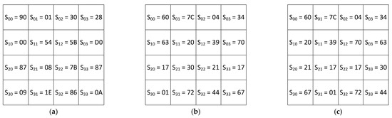
Figure 1.
AES encryption: (a) the input to the SubBytes transformer; (b) the output of the SubBytes transformer; (c) the output of the ShiftRows transformer.
Figure 2 shows the state at the output of the MixColumns linear transformer and the execution of the AddRoundKey transformation with the following key:
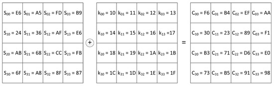
Figure 2.
AES encryption: MixColumns output + Key = Cipher text.
The result of performing an AddRoundKey transformation is 16 bytes of cipher text:
Let us consider the decryption process in AES. The decryptor input is a cipher text containing 16 bytes, which is summed modulo two with the key. The process of InvAddRoundKey conversion is shown in Figure 3. The obtained result is fed to the input of the InvMixColumns transformer.
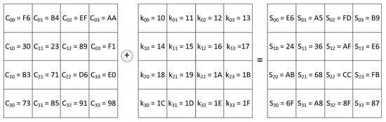
Figure 3.
AES decryption: Cipher text + Key = InvMixColumns input.
The byte values obtained after executing the InvMixColumns transformation are shown in Figure 4a. The results of the InvShiftRows transformation are shown in Figure 4b. The result of executing InvSubBytes transformation is the text shown in Figure 4c.
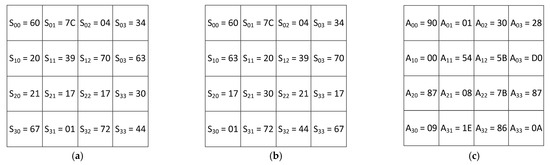
Figure 4.
AES decryption: (a) the results of the InvMixColumns transformation; (b) the results of the InvShiftRows transformation; (c) the results of the InvSubBytes transformation.
Let us consider the performance of AES encryption procedure with the RCPR. For this purpose, the input data are represented as RCPR CCs. The first byte is passed to the input of the AES encryptor. Then it is passed to the forward converter from positional code to RCPR. Let us present this byte in binary and polynomial forms:
Then, the following RCPR CC consisting of two residues is obtained at the output of the converter:
In other words, we have . Similarly, the rest of the 15 input bytes are converted, so we obtain the following:
Let us present the key consisting of 16 bytes in RCPR. As a result, we obtain the following:
Let us consider a nonlinear SubBytes transformation using a byte. The byte is input to the transformer. At the intersection of row “9” and column “0” of Table A9 in the Appendix C, there is a number , which is passed to the output of the SubBytes transformer.
Let us consider the operation of the fault-tolerant SubBytes transformer with RCPR. According to Section 4.1, the nonlinear transformation is implemented as follows:
- The first byte, in the form of two residues , arrives at the input of the fault-tolerant SubBytes transformer, which contains four tables of bits.
- In the Appendix A, Table A1 and Table A2 show the informational residues of the output byte . Table A3 and Table A4 show the control residues of the output byte . There are informational residues and at the intersection of row «8» and column «E» in Table A1 and Table A2. There are control residues and at the intersection of row «8» and column «E» in Table A3 and Table A4. As a result of transformation (39), we obtain the following:
- Using the informational residues of the output byte, let us calculate new control residues according to (40). We obtain the following:
- We calculate the error syndrome according to (41) using two adders modulo two. We obtain the following:
- The residues of the output byte are fed to the corrective adders modulo two. Since the error syndrome is , the combination does not contain errors.
Let us suppose an error occurs in the first residue when reading the data and its depth is equal to . Then the distorted residue, according to (25), will take the following form:
Then, the distorted CC has the following form:
Using the informational residues of the output byte, let us calculate new control residues according to (40). We obtain the following:
Using two adders modulo two we calculate the error syndrome according to (41). We obtain the following:
Since , the error vector is used in error correction. According to (42), we have the following:
The error is corrected.
Let us consider the operation of the fault-tolerant MixColumns transformer with RCPR. First, let us perform this operation using bytes. Let MixColumns transformer has four bytes as the input: , , , . Then, according to (45), we have the following:
According to Section 4.2, the linear transformation is implemented as follows:
- The input of the fault-tolerant transformer receives four bytes, represented in RCPR as , , , .
- Then, using the four tables, we obtain the CC for the product of a byte and a constant {02}. In the Appendix B, Table A5 and Table A6 show the informational residues after the multiplication operation. Table A7 and Table A8 show the control residues. In the considered example, the computation of the zero byte represented in RCPR is implemented according to (46). Thenwhere .
From (50), we can see that S(00) and S(10) are subjected to multiplication by a constant. In this case, the inputs of Table A5, Table A6, Table A7 and Table A8 first receive two informational residues . The residues of the resulting product are at the intersection of row «A» and column «4». Then the inputs of Table A5, Table A6, Table A7 and Table A8 receives two informational residues . The residues of the resulting product are at the intersection of row «6» and column «B». Table 2 shows the application of (50).
Table 2.
Execution of MixColumns transformation with RCPR.
The result is , which is subjected to error correction.
- 3.
- Using the informational residues of the output byte, let us calculate new control residues according to (40). We obtain
- 4.
- Using two adders modulo two, we calculate the error syndrome according to (41). We obtain
- 5.
- The residues of the output byte are fed to the corrective adders modulo two. Since the error syndrome is , the CC does not contain errors.
Let us suppose there was an error while reading data in the second residue, and its depth is equal to . Then the distorted residue, according to (25), will take the following form:
Then, the distorted CC has the following form:
Using the informational residues of the output byte, let us calculate the new control residues according to (40). We obtain
Using two adders modulo two, we calculate the error syndrome according to (41). We obtain
Since and , the error occurred in the second residue. Then the error vector is equal to . According to (42), we have the following:
The error is corrected.
Figure 5a shows CCs at the output of the forward converter from positional code to RCPR. These CCs are passed to the input of the nonlinear SubBytes transformer. The output of the SubBytes transformer produces the result shown in Figure 5b. At the same time, the redundant RCPR CCs are obtained from the output of this transformer. Figure 5c shows the state at the output of the ShiftRows transformer.
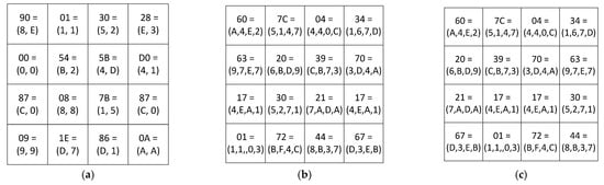
Figure 5.
AES encryption with RCPR: (a) the output of the forward converter; (b) the output of the SubBytes transformer; (c) the output of the ShiftRows transformer.
Figure 6 shows the state at the output of the MixColumns linear transformer and the execution of the AddRoundKey transformation with the key represented in RCPR according to (49).
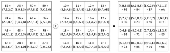
Figure 6.
AES encryption with RCPR: MixColumns output + Key = Cipher text.
In this case, only the informational residues are added. The result of performing the AddRoundKey transformation is 16 bytes of the cipher text represented in RCPR. CCs are then subjected to the inverse conversion from RCPR to positional code. This operation is performed based on the Chinese Remainder Theorem (CRT) according to (21). and are orthogonal bases for RCPR with two informational modules and . In this case, the range of allowed combinations is . Let us perform the inverse conversion for the zero byte . Then, according to (21), we have
The decryption process in AES with RCPR is shown in Figure 7 and Figure 8. The cipher text is first converted from positional code to RCPR. Then the InvAddRoundKey transformation is performed with RCPR, which is shown in Figure 7. The obtained result is passed to the input of InvMixColumns transformer.
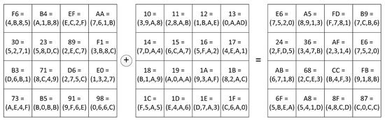
Figure 7.
AES decryption with RCPR: Cipher text + Key = InvMixColumns input.
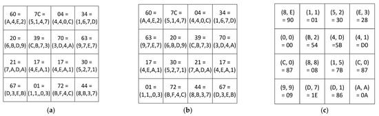
Figure 8.
AES decryption with RCPR: (a) the results of the InvMixColumns transformation; (b) the results of InvShiftRows transformation; (c) the result of the InvSubBytes transformation.
The byte residues obtained after executing the InvMixColumns transformation with RCPR are shown in Figure 8a. The results of InvShiftRows transformation with RCPR are shown in Figure 8b. The result of the InvSubBytes transformation is the plaintext that is obtained using the CRT-based conversion. The result is shown in Figure 8c.
Let us conduct a comparative analysis of the cybersecurity of VANET using various methods to increase the reliability of AES encryption systems. In this analysis, only the method presented in [84] and the duplication method are considered. ECCs are not considered in the comparative analysis, since most of these codes are not arithmetic and cannot be used for calculations performed in AES encryption algorithm. These codes are widely used to improve noise immunity of the data transmission system (cyclic codes, BCH codes, Reed-Solomon codes). Also, TMR method was not considered in the comparative analysis. It is known that TMR method makes it possible to effectively correct single calculation errors that are caused by a failure or malfunction. However, this method has a disadvantage. In order to implement it, it is necessary to use three encryptors/decryptors that work in parallel. At the same time, in order to implement the developed method, it is necessary to double the number of tables for SubBytes and MixColumns, as well as introduce 2 additional shift registers modulo the control module and 8 adders modulo two.
The results of the evaluation of the redundant RCPR were obtained by iterating over all possible code combinations containing single, double and triple errors. The error syndrome was calculated according to (24) for each such combination. Then equal syndromes were selected. Obtaining such syndromes, EDCU will not be able to correct the distorted residues.
Figure 9a shows the capabilities of the developed method using the correction algorithm (22)–(24) and the method [84] for detecting errors caused by failures that occur during the operation of AES encryption system. The analysis of Figure 9a shows that the method [84] makes it possible to detect 100% of single and 75% of double errors. A single error is a distortion of one digit of the code combination caused by the first failure of the equipment. If a second failure or failure occurs, a double error occurs. The developed method provides detection of 100% of single and double errors, as well as 75% of triple errors.
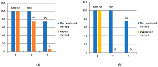
Figure 9.
Comparative analysis of error correction capabilities of methods for improving fault tolerance of AES encryption system; (a) comparison of the developed method with the method [84] in terms of error detection rate; (b) comparison of the developed method with duplication method in terms of error correction rate.
Since the method [84] does not allow for error correction, a comparative analysis of the developed method will be carried out by AES encryption system using the duplication method. An analysis of Figure 9b shows that the duplication method makes it possible to fend off 100% of single errors. If a second failure occurs, AES encryption system, which uses the duplication method, fails and cannot ensure cybersecurity during data exchange. The developed method makes it possible to effectively deal with the flow of failures that occur during the operation of AES encryption system. It fends off 100% of single errors caused by the first failure, as well as 100% of errors when the second failure occurs, as well as 75% of errors when the third failure occurs.
To assess the impact of the developed method on the overall delay of AES encryption, a prototyped model of a fault-tolerant encryptor based on Artix-7 FPGA (xc7a12ticsg325-1L) was implemented. Comparisons were made with a prototyped encryptor model using the classical AES encryption algorithm. Computer-aided design Xilinx Vivado-HLS 2018 was used in order to study the built models. The hardware costs for the implementation of these models are presented in Table 3.
Table 3.
Hardware costs for the implementation of a fault-tolerant encryptor.
A comparative analysis was conducted on a single round of encryption. The following were selected as the initial data:
- The plaintext that consists of 128 bits.
- The plaintext in the form of bytes represented in a hexadecimal system: 30 28 00 54 5B D0 87, 08, 7B 87 09 1E 86 0A.
- The key that consists of 128 bits.
- The key in the form of bytes represented in a hexadecimal system: 10 11 12 13 14 15 16 17 18 19 1A 1B 1C 1D 1E 1F.
As a result of the conducted research, the following data were obtained. When implementing the classical encryptor, the time spent on one round of encryption was 330 ns. When using the developed error correction method for RCPR, it took 426 ns to perform one round of encryption. Thus, the time spent on encryption was increased by 96 ns. It means that the delay in performing one round of encryption due to the application of the developed error correction method for RCPR was increased by 1.29 times.
Summarizing the results obtained, the following conclusion can be drawn. The novelty of the developed method lies in the fact that it allows us to correct errors using only one control module of the fourth degree. In [84], the authors only managed to detect an error in operation of AES encryptor, but not to correct it. In addition, the developed method provides lower hardware costs compared to the projection method [67] and its modification [68], the interval-index characteristic calculation method [69] and MRS method [70,71]. Thus, it is obvious that the application of the developed method using the correction algorithm (22)–(24) makes it possible to ensure a constant level of cybersecurity even with two consecutive failures in AES encryption system.
6. Conclusions
One of the effective ways to counteract cyberattacks implemented on the VANET is to use AES encryption algorithm. However, during the operation of AES encryption systems, failures and malfunctions can occur sequentially, which negatively affects the cybersecurity of vehicles. The article describes a method for ensuring the fault tolerance of AES encryption systems based on RCPR. When the first failure occurs, the method [84] is only able to detect 100% of the errors caused by this failure, and the duplication method and the developed method using the error detection and correction algorithm (22)–(24) make it possible to correct these errors. In the event of a second failure, the developed method ensures that AES encryption system remains operational, correcting 100% of the errors caused by this failure. Only if a third failure occurs during the operation of AES encryption system is the developed method able to correct 75% of errors in code combinations. Thus, the developed method makes it possible to fend off cyberattacks on vehicles and ensure a higher level of cybersecurity of the VANET by correcting errors in AES encryption system.
Author Contributions
Conceptualization, I.A.K. and A.A.O.; methodology, I.A.K.; validation, D.V.D. and I.A.P.; formal analysis, A.A.O.; investigation, A.A.O.; data curation, D.V.D.; writing—original draft preparation, I.A.K.; writing—review and editing, A.A.O.; visualization, V.S.S.; supervision, I.A.K.; project administration, I.A.K.; funding acquisition, I.A.K. All authors have read and agreed to the published version of the manuscript.
Funding
The research was supported by the Russian Science Foundation Grant No 25-71-30007, https://rscf.ru/project/25-71-30007/ (accessed on 7 August 2025).
Data Availability Statement
The original contributions presented in this study are included in the article. Further inquiries can be directed to the corresponding author.
Conflicts of Interest
The authors declare no conflicts of interest.
Appendix A
Table A1.
The table of formation of the first informational residue for SubBytes transformation. We used bold on the top and left sides of the table due to the meaning of the table. Its purpose is to find a correct output by the two inputs. Such output is placed at the intersection of the column and the row that are determined by two inputs.
| 0 | 1 | 2 | 3 | 4 | 5 | 6 | 7 | 8 | 9 | A | B | C | D | E | F | |
|---|---|---|---|---|---|---|---|---|---|---|---|---|---|---|---|---|
| 0 | 9 | D | A | F | 8 | 4 | A | E | 2 | 8 | 4 | 3 | 8 | 5 | 2 | 1 |
| 1 | 9 | 5 | 2 | 0 | 3 | 2 | B | F | 7 | D | 8 | E | B | 7 | A | 6 |
| 2 | 2 | 9 | E | 0 | 6 | 2 | 7 | 4 | 9 | F | 7 | 0 | 9 | B | A | 3 |
| 3 | F | 0 | 5 | 2 | 5 | 7 | E | E | 3 | D | 6 | C | F | B | A | 3 |
| 4 | D | 9 | A | 0 | 0 | 7 | D | D | A | B | 7 | 8 | E | C | 2 | 6 |
| 5 | B | 3 | 4 | 1 | 5 | 1 | E | 3 | 0 | A | 3 | 5 | 0 | 2 | B | B |
| 6 | B | 4 | 6 | B | C | 2 | 5 | 8 | F | 1 | 2 | 9 | 6 | 6 | 1 | C |
| 7 | 5 | F | C | 1 | D | 5 | 1 | 2 | 4 | 9 | F | E | 9 | 8 | 0 | 7 |
| 8 | B | 4 | 2 | 2 | D | 4 | 7 | 1 | 5 | 6 | D | 8 | E | D | A | 1 |
| 9 | F | F | 4 | F | 6 | 0 | 0 | 9 | 5 | 1 | 4 | 3 | 6 | E | A | A |
| A | 0 | 6 | D | E | 4 | 3 | C | 8 | 8 | 5 | D | 3 | 3 | C | 4 | E |
| B | 1 | 0 | 6 | 1 | 7 | E | C | A | D | C | 2 | D | C | 8 | 6 | C |
| C | 4 | 4 | 6 | C | 5 | C | 7 | 2 | 5 | B | 4 | 1 | C | 7 | A | 9 |
| D | 3 | 8 | D | E | 0 | 5 | 7 | B | 0 | A | 7 | C | 1 | 3 | 8 | 9 |
| E | F | 9 | F | 1 | 9 | 6 | E | 5 | 8 | 3 | 7 | 8 | B | A | 6 | A |
| F | 9 | 1 | 8 | 0 | F | 4 | C | B | B | 3 | 7 | D | 9 | E | F | F |
Table A2.
The table of formation of the second informational residue for SubBytes transformation.
Table A2.
The table of formation of the second informational residue for SubBytes transformation.
| 0 | 1 | 2 | 3 | 4 | 5 | 6 | 7 | 8 | 9 | A | B | C | D | E | F | |
|---|---|---|---|---|---|---|---|---|---|---|---|---|---|---|---|---|
| 0 | 7 | B | 2 | 2 | 3 | 7 | 9 | 8 | E | 7 | 0 | 2 | F | D | 2 | E |
| 1 | F | 1 | 0 | 2 | 3 | 9 | 1 | D | E | D | 8 | 1 | 4 | 3 | 1 | 2 |
| 2 | 8 | 4 | A | 4 | D | 4 | A | C | 5 | 1 | B | 3 | A | A | B | 4 |
| 3 | 3 | 6 | 7 | 6 | 5 | D | E | B | 7 | 2 | 5 | D | 5 | 3 | D | C |
| 4 | 5 | D | F | F | 8 | 2 | 8 | 4 | E | D | 1 | 5 | D | B | A | E |
| 5 | C | 9 | 4 | 8 | A | F | 9 | D | D | 0 | E | 4 | B | C | 9 | 8 |
| 6 | B | B | 3 | 0 | A | 7 | B | 6 | 6 | 5 | B | 2 | F | 8 | A | 3 |
| 7 | 8 | A | 2 | 9 | 6 | 9 | 0 | D | F | E | 7 | 0 | 0 | 0 | E | 5 |
| 8 | 6 | D | 3 | 1 | F | 3 | 6 | D | 2 | 6 | 7 | 2 | F | 1 | 4 | C |
| 9 | 4 | F | 5 | E | C | A | C | 1 | 6 | 1 | A | 5 | 9 | 7 | 8 | 6 |
| A | 5 | A | E | 6 | 1 | 8 | C | C | A | C | 3 | A | 0 | 8 | 8 | 4 |
| B | 4 | 1 | B | 7 | 4 | C | 9 | 5 | C | 0 | F | 0 | 7 | D | 0 | F |
| C | E | 6 | 1 | 6 | E | E | 8 | 5 | 3 | 5 | 9 | B | 4 | 0 | 3 | 9 |
| D | B | B | 9 | 2 | 0 | F | 9 | F | 7 | C | 7 | 1 | 3 | 6 | 4 | 6 |
| E | C | C | 9 | 6 | 8 | 4 | 5 | 0 | E | 1 | F | 1 | E | 7 | 7 | A |
| F | B | 2 | 9 | 9 | 0 | 2 | 5 | 2 | 7 | F | C | A | 3 | 3 | 8 | B |
Table A3.
The table of formation of the first control residue for SubBytes transformation.
Table A3.
The table of formation of the first control residue for SubBytes transformation.
| 0 | 1 | 2 | 3 | 4 | 5 | 6 | 7 | 8 | 9 | A | B | C | D | E | F | |
|---|---|---|---|---|---|---|---|---|---|---|---|---|---|---|---|---|
| 0 | E | 6 | 8 | D | B | 3 | 3 | 6 | C | F | 4 | 1 | 7 | 8 | 0 | F |
| 1 | 6 | 4 | 2 | 2 | 0 | B | A | 2 | 9 | 0 | 0 | F | F | 4 | B | 4 |
| 2 | A | D | 4 | 4 | B | 6 | D | 8 | C | E | C | 3 | 3 | 1 | 1 | 7 |
| 3 | C | 6 | 2 | 4 | 0 | A | 0 | 5 | 4 | F | 3 | 1 | A | 8 | 7 | F |
| 4 | 8 | 4 | 5 | F | 8 | 5 | 5 | 9 | 4 | 6 | 6 | D | 3 | 7 | 8 | 8 |
| 5 | 7 | A | 0 | 9 | F | E | 7 | E | D | A | D | 1 | B | E | 2 | 3 |
| 6 | 0 | F | 5 | B | 6 | 5 | E | E | 9 | 4 | 9 | B | 9 | E | B | F |
| 7 | D | 5 | E | 8 | B | C | 1 | F | B | 7 | 8 | E | 9 | 8 | E | 2 |
| 8 | D | 9 | 1 | 3 | 2 | 7 | 1 | C | 7 | 0 | A | A | 1 | C | E | D |
| 9 | B | 0 | 1 | 1 | A | A | C | 8 | 3 | 0 | E | 6 | F | 9 | 2 | C |
| A | 5 | C | 3 | 8 | 5 | B | 0 | 4 | 2 | 9 | E | 9 | 3 | 4 | C | A |
| B | 5 | 1 | D | 6 | 3 | 2 | 5 | F | 1 | C | D | D | B | 5 | 6 | 3 |
| C | A | 2 | 7 | A | B | 2 | F | 7 | 6 | E | D | A | 8 | 7 | 9 | 0 |
| D | 8 | 3 | 4 | C | 0 | A | E | 4 | 7 | C | 0 | D | 2 | 5 | C | F |
| E | 3 | 5 | 6 | 7 | 1 | 2 | B | 5 | 6 | 2 | 8 | 9 | 5 | D | 1 | 0 |
| F | 2 | 3 | 1 | 9 | F | 6 | 9 | 9 | C | C | B | 7 | A | D | 7 | 4 |
Table A4.
The table of formation of the second control residue for SubBytes transformation.
Table A4.
The table of formation of the second control residue for SubBytes transformation.
| 0 | 1 | 2 | 3 | 4 | 5 | 6 | 7 | 8 | 9 | A | B | C | D | E | F | |
|---|---|---|---|---|---|---|---|---|---|---|---|---|---|---|---|---|
| 0 | 7 | 8 | E | B | E | A | B | D | D | 6 | 4 | 7 | 5 | C | 6 | E |
| 1 | 4 | 7 | 2 | 4 | 5 | 3 | 9 | 6 | 8 | 4 | B | C | 3 | 1 | 8 | 2 |
| 2 | 1 | 1 | 9 | 8 | F | A | 0 | F | 3 | D | 2 | 6 | E | E | F | B |
| 3 | 9 | C | B | E | F | E | 1 | B | D | 9 | C | 5 | 5 | D | 3 | 8 |
| 4 | 7 | 0 | 7 | D | 3 | 3 | E | 5 | 5 | 2 | 5 | 2 | 7 | 9 | 5 | 9 |
| 5 | 0 | 2 | C | 2 | 2 | C | F | A | 9 | A | C | D | 5 | 9 | A | 8 |
| 6 | E | 1 | 0 | D | D | C | 0 | 4 | 3 | B | 7 | D | B | 5 | 6 | A |
| 7 | 6 | 8 | 8 | 0 | 1 | 4 | 1 | B | 9 | 6 | 1 | E | 9 | 8 | F | D |
| 8 | 7 | B | 4 | 0 | 0 | 2 | B | 8 | 1 | A | 3 | C | 3 | F | 2 | A |
| 9 | 7 | 2 | E | 0 | D | 7 | B | B | 9 | 3 | 3 | 9 | 7 | 0 | 9 | 6 |
| A | A | 1 | 2 | 2 | 6 | 0 | 7 | 3 | F | E | B | 4 | 3 | F | 7 | 6 |
| B | 9 | 2 | 3 | F | F | 5 | D | 0 | 6 | C | F | D | 2 | 1 | 6 | 1 |
| C | B | 8 | 4 | 0 | A | 3 | 4 | 8 | 3 | 1 | 5 | 4 | 4 | 7 | C | 8 |
| D | 6 | D | C | A | 0 | 8 | 6 | 6 | E | 1 | 9 | E | 7 | F | 0 | 5 |
| E | 4 | 2 | E | D | A | E | 4 | 5 | 7 | 1 | A | A | 4 | 4 | 8 | D |
| F | C | 5 | 9 | 1 | F | 0 | 6 | F | 5 | E | C | A | F | 8 | C | A |
Appendix B
Table A5.
The table of formation of the first informational residue of the result of multiplication by the constant 216.
Table A5.
The table of formation of the first informational residue of the result of multiplication by the constant 216.
| 0 | 1 | 2 | 3 | 4 | 5 | 6 | 7 | 8 | 9 | A | B | C | D | E | F | |
|---|---|---|---|---|---|---|---|---|---|---|---|---|---|---|---|---|
| 0 | 0 | D | D | 0 | 0 | D | D | 0 | D | 0 | 0 | D | D | 0 | 0 | D |
| 1 | F | 2 | 2 | F | F | 2 | 2 | F | 2 | F | F | 2 | 2 | F | F | 2 |
| 2 | 9 | 4 | 4 | 9 | 9 | 4 | 4 | 9 | 4 | 9 | 9 | 4 | 4 | 9 | 9 | 4 |
| 3 | 6 | B | B | 6 | 6 | B | B | 6 | B | 6 | 6 | B | B | 6 | 6 | B |
| 4 | 8 | 5 | 5 | 8 | 8 | 5 | 5 | 8 | 5 | 8 | 8 | 5 | 5 | 8 | 8 | 5 |
| 5 | 7 | A | A | 7 | 7 | A | A | 7 | A | 7 | 7 | A | A | 7 | 7 | A |
| 6 | 1 | C | C | 1 | 1 | C | C | 1 | C | 1 | 1 | C | C | 1 | 1 | C |
| 7 | E | 3 | 3 | E | E | 3 | 3 | E | 3 | E | E | 3 | 3 | E | E | 3 |
| 8 | E | 3 | 3 | E | E | 3 | 3 | E | 3 | E | E | 3 | 3 | E | E | 3 |
| 9 | 1 | C | C | 1 | 1 | C | C | 1 | C | 1 | 1 | C | C | 1 | 1 | C |
| A | 7 | A | A | 7 | 7 | A | A | 7 | A | 7 | 7 | A | A | 7 | 7 | A |
| B | 8 | 5 | 5 | 8 | 8 | 5 | 5 | 8 | 5 | 8 | 8 | 5 | 5 | 8 | 8 | 5 |
| C | 6 | B | B | 6 | 6 | B | B | 6 | B | 6 | 6 | B | B | 6 | 6 | B |
| D | 9 | 4 | 4 | 9 | 9 | 4 | 4 | 9 | 4 | 9 | 9 | 4 | 4 | 9 | 9 | 4 |
| E | F | 2 | 2 | F | F | 2 | 2 | F | 2 | F | F | 2 | 2 | F | F | 2 |
| F | 0 | D | D | 0 | 0 | D | D | 0 | D | 0 | 0 | D | D | 0 | 0 | D |
Table A6.
The table of formation of the second informational residue of the result of multiplication by the constant 216.
Table A6.
The table of formation of the second informational residue of the result of multiplication by the constant 216.
| 0 | 1 | 2 | 3 | 4 | 5 | 6 | 7 | 8 | 9 | A | B | C | D | E | F | |
|---|---|---|---|---|---|---|---|---|---|---|---|---|---|---|---|---|
| 0 | 0 | E | 8 | 6 | 8 | 6 | 0 | E | 5 | B | D | 3 | D | 3 | 5 | B |
| 1 | C | 2 | 4 | A | 4 | A | C | 2 | 9 | 7 | 1 | F | 1 | F | 9 | 7 |
| 2 | C | 2 | 4 | A | 4 | A | C | 2 | 9 | 7 | 1 | F | 1 | F | 9 | 7 |
| 3 | 0 | E | 8 | 6 | 8 | 6 | 0 | E | 5 | B | D | 3 | D | 3 | 5 | B |
| 4 | 0 | E | 8 | 6 | 8 | 6 | 0 | E | 5 | B | D | 3 | D | 3 | 5 | B |
| 5 | C | 2 | 4 | A | 4 | A | C | 2 | 9 | 7 | 1 | F | 1 | F | 9 | 7 |
| 6 | C | 2 | 4 | A | 4 | A | C | 2 | 9 | 7 | 1 | F | 1 | F | 9 | 7 |
| 7 | 0 | E | 8 | 6 | 8 | 6 | 0 | E | 5 | B | D | 3 | D | 3 | 5 | B |
| 8 | C | 2 | 4 | A | 4 | A | C | 2 | 9 | 7 | 1 | F | 1 | F | 9 | 7 |
| 9 | 0 | E | 8 | 6 | 8 | 6 | 0 | E | 5 | B | D | 3 | D | 3 | 5 | B |
| A | 0 | E | 8 | 6 | 8 | 6 | 0 | E | 5 | B | D | 3 | D | 3 | 5 | B |
| B | C | 2 | 4 | A | 4 | A | C | 2 | 9 | 7 | 1 | F | 1 | F | 9 | 7 |
| C | C | 2 | 4 | A | 4 | A | C | 2 | 9 | 7 | 1 | F | 1 | F | 9 | 7 |
| D | 0 | E | 8 | 6 | 8 | 6 | 0 | E | 5 | B | D | 3 | D | 3 | 5 | B |
| E | 0 | E | 8 | 6 | 8 | 6 | 0 | E | 5 | B | D | 3 | D | 3 | 5 | B |
| F | C | 2 | 4 | A | 4 | A | C | 2 | 9 | 7 | 1 | F | 1 | F | 9 | 7 |
Table A7.
The table of formation of the first control residue of the result of multiplication by the constant 216.
Table A7.
The table of formation of the first control residue of the result of multiplication by the constant 216.
| 0 | 1 | 2 | 3 | 4 | 5 | 6 | 7 | 8 | 9 | A | B | C | D | E | F | |
|---|---|---|---|---|---|---|---|---|---|---|---|---|---|---|---|---|
| 0 | 0 | 3 | 5 | 6 | 8 | B | D | E | 8 | B | D | E | 0 | 3 | 5 | 6 |
| 1 | 3 | 0 | 6 | 5 | B | 8 | E | D | B | 8 | E | D | 3 | 0 | 6 | 5 |
| 2 | 5 | 6 | 0 | 3 | D | E | 8 | B | D | E | 8 | B | 5 | 6 | 0 | 3 |
| 3 | 6 | 5 | 3 | 0 | E | D | B | 8 | E | D | B | 8 | 6 | 5 | 3 | 0 |
| 4 | 8 | B | D | E | 0 | 3 | 5 | 6 | 0 | 3 | 5 | 6 | 8 | B | D | E |
| 5 | B | 8 | E | D | 3 | 0 | 6 | 5 | 3 | 0 | 6 | 5 | B | 8 | E | D |
| 6 | D | E | 8 | B | 5 | 6 | 0 | 3 | 5 | 6 | 0 | 3 | D | E | 8 | B |
| 7 | E | D | B | 8 | 6 | 5 | 3 | 0 | 6 | 6 | 3 | 0 | E | D | B | 8 |
| 8 | 2 | 1 | 7 | 4 | A | 9 | F | C | A | 9 | F | C | 2 | 1 | 7 | 4 |
| 9 | 1 | 2 | 4 | 7 | 9 | A | C | F | 9 | A | C | F | 1 | 2 | 4 | 7 |
| A | 7 | 4 | 2 | 1 | F | C | A | 9 | F | C | A | 9 | 7 | 4 | 2 | 1 |
| B | 4 | 7 | 1 | 2 | C | F | 9 | A | C | F | 9 | A | 4 | 7 | 1 | 2 |
| C | A | 9 | F | C | 2 | 1 | 7 | 4 | 2 | 1 | 7 | 4 | A | 9 | F | C |
| D | 9 | A | C | F | 1 | 2 | 4 | 7 | 1 | 2 | 4 | 4 | 9 | A | C | F |
| E | F | C | A | 9 | 7 | 4 | 2 | 1 | 7 | 4 | 2 | 1 | F | C | A | 9 |
| F | C | F | 9 | A | 4 | 7 | 1 | 2 | 4 | 7 | 1 | 2 | C | F | 9 | A |
Table A8.
The table of formation of the second control residue of the result of multiplication by the constant 216.
Table A8.
The table of formation of the second control residue of the result of multiplication by the constant 216.
| 0 | 1 | 2 | 3 | 4 | 5 | 6 | 7 | 8 | 9 | A | B | C | D | E | F | |
|---|---|---|---|---|---|---|---|---|---|---|---|---|---|---|---|---|
| 0 | 0 | E | 2 | C | F | 1 | D | 3 | 7 | 9 | 5 | B | 8 | 6 | A | 4 |
| 1 | 8 | 6 | A | 4 | 7 | 9 | 5 | B | F | 1 | D | 3 | 0 | E | 2 | C |
| 2 | E | 0 | C | 2 | 1 | F | 3 | D | 9 | 7 | B | 5 | 6 | 8 | 4 | A |
| 3 | 6 | 8 | 4 | A | 9 | 7 | B | 5 | 1 | F | 3 | D | E | 0 | C | 2 |
| 4 | 8 | 6 | A | 4 | 7 | 9 | 5 | B | F | 1 | D | 3 | 0 | E | 2 | C |
| 5 | 0 | E | 2 | C | F | 1 | D | 3 | 7 | 9 | 5 | B | 8 | 6 | A | 4 |
| 6 | 6 | 8 | 4 | A | 9 | 7 | B | 5 | 1 | F | 3 | D | E | 0 | C | 2 |
| 7 | E | 0 | C | 2 | 1 | F | 3 | D | 9 | 7 | B | 5 | 6 | 8 | 4 | A |
| 8 | 9 | 7 | B | 5 | 6 | 8 | 4 | A | E | 0 | C | 2 | 1 | F | 3 | D |
| 9 | 1 | F | 3 | D | E | 0 | C | 2 | 6 | 8 | 4 | A | 9 | 7 | B | 5 |
| A | 7 | 9 | 5 | B | 8 | 6 | A | 4 | 0 | E | 2 | C | F | 1 | D | 3 |
| B | F | 1 | D | 3 | 0 | E | 2 | C | 8 | 6 | A | 4 | 7 | 9 | 5 | B |
| C | 1 | F | 3 | D | E | 0 | C | 2 | 6 | 8 | 4 | A | 9 | 7 | B | 5 |
| D | 9 | 7 | B | 5 | 6 | 8 | 4 | A | E | 0 | C | 2 | 1 | F | 3 | D |
| E | F | 1 | D | 3 | 0 | E | 2 | C | 8 | 6 | A | 4 | 7 | 9 | 5 | B |
| F | 7 | 9 | 5 | B | 8 | 6 | A | 4 | 0 | E | 2 | C | F | 1 | D | 3 |
Appendix C
Table A9.
The table of formation of the result of SubBytes transformation.
Table A9.
The table of formation of the result of SubBytes transformation.
| 0 | 1 | 2 | 3 | 4 | 5 | 6 | 7 | 8 | 9 | A | B | C | D | E | F | |
|---|---|---|---|---|---|---|---|---|---|---|---|---|---|---|---|---|
| 0 | 63 | 7C | 77 | 7B | F2 | 6B | 6F | C5 | 30 | 01 | 67 | 2B | FE | D7 | AB | 76 |
| 1 | CA | 82 | C9 | 7D | FA | 59 | 47 | F0 | AD | D4 | A2 | AF | 9C | A4 | 72 | C0 |
| 2 | B7 | FD | 93 | 26 | 36 | 3F | F7 | CC | 34 | A5 | E5 | F1 | 71 | D8 | 31 | 15 |
| 3 | 04 | C7 | 23 | C3 | 18 | 96 | 05 | 9A | 07 | 12 | 80 | E2 | EB | 27 | B2 | 75 |
| 4 | 09 | 83 | 2C | 1A | 1B | 6E | 5A | A0 | 52 | 3B | D6 | B3 | 29 | E3 | 2F | 84 |
| 5 | 53 | D1 | 00 | ED | 20 | FC | B1 | 5B | 6A | CB | BE | 39 | 4A | 4C | 58 | CF |
| 6 | D0 | EF | AA | FB | 43 | 4D | 33 | 85 | 45 | F9 | 02 | 7F | 50 | 3C | 9F | A8 |
| 7 | 51 | A3 | 40 | 8F | 92 | 9D | 38 | F5 | BC | B6 | DA | 21 | 10 | FF | F3 | D2 |
| 8 | CD | 0C | 13 | EC | 5F | 97 | 44 | 17 | C4 | A7 | 7E | 3D | 64 | 5D | 19 | 73 |
| 9 | 60 | 81 | 4F | DC | 22 | 2A | 90 | 88 | 46 | EE | B8 | 14 | DE | 5E | 0B | DB |
| A | E0 | 32 | 3A | 0A | 49 | 06 | 24 | 5C | C2 | D3 | AC | 62 | 91 | 95 | E4 | 79 |
| B | E7 | C8 | 37 | 6D | 8D | D5 | 4E | A9 | 6C | 56 | F4 | EA | 65 | 7A | AE | 08 |
| C | BA | 78 | 25 | 2E | 1C | A6 | B4 | C6 | E8 | DD | 74 | 1F | 4B | BD | 8B | 8A |
| D | 70 | 3E | B5 | 66 | 48 | 03 | F6 | 0E | 61 | 35 | 57 | B9 | 86 | C1 | 1D | 9E |
| E | E1 | F8 | 98 | 11 | 69 | D9 | 8E | 94 | 9B | 1E | 87 | E9 | CE | 55 | 28 | DF |
| F | 8C | A1 | 89 | 0D | BF | E6 | 42 | 68 | 41 | 99 | 2D | 0F | B0 | 54 | BB | 16 |
References
- Wang, F.-Y.; Lin, Y.; Ioannou, P.A.; Vlacic, L.; Liu, X.; Eskandarian, A.; Lv, Y.; Na, X.; Cebon, D.; Ma, J.; et al. Transportation 5.0: The DAO to Safe, Secure, and Sustainable Intelligent Transportation Systems. IEEE Trans. Intell. Transp. Syst. 2023, 24, 10262–10278. [Google Scholar] [CrossRef]
- Assem, R.; Lyamine, G.; Abderrezak, B.; Zineb, S.; Abdelkrim, L. Data Processing from VANETs to IoV: Literature Review. In Proceedings of the Future Technologies Conference (FTC), Vancouver, BC, Canada, 1 November 2023; Springer Nature: Cham, Switzerland, 2023; pp. 472–494. [Google Scholar] [CrossRef]
- Paul, A.; Chilamkurti, N.; Daniel, A.; Rho, S. Intelligent Vehicular Networks and Communications: Fundamentals, Architectures and Solutions; Elsevier Inc.: Amsterdam, The Netherlands, 2016; p. 227. [Google Scholar]
- Aung, N.; Zhang, W.; Dhelim, S.; Ai, Y. Accident Prediction System Based on Hidden Markov Model for Vehicular Ad-Hoc Network in Urban Environments. Information 2018, 9, 311. [Google Scholar] [CrossRef]
- Businesses Will Lose Over $5 Trillion to Cybercrime Data Breaches by 2024. Available online: https://mediabrief.com/cybercrime-losses-report-juniper/ (accessed on 13 May 2025).
- Abbas, A.H.; Ahmed, A.J.; Rashid, S.A. A Cross-Layer Approach MAC/NET with Updated-GA (MNUG-CLA)-Based Routing Protocol for VANET Network. World Electr. Veh. J. 2022, 13, 87. [Google Scholar] [CrossRef]
- Karabulut, M.A.; Shah, A.F.M.S.; Ilhan, H. A Novel MIMO-OFDM Based MAC Protocol for VANETs. IEEE Trans. Intell. Transp. Syst. 2022, 23, 20255–20267. [Google Scholar] [CrossRef]
- Jeon, S.; Lee, Y.; Lee, I. Software Defined Range-Proof Authentication Mechanism for Untraceable Digital ID. Comput. Model. Eng. Sci. 2025, 142, 3213–3228. [Google Scholar] [CrossRef]
- Shlaka, S.M.; Wahab, H.B.A. The Zero-Knowledge Proof Technique: Limitations and Challenges. In Proceedings of the 2023 Second International Conference on Advanced Computer Applications (ACA), Misan, Iraq, 27–28 February 2023; pp. 90–95. [Google Scholar] [CrossRef]
- Srivastava, A.; Verma, S.; Kavita; Jhanjhi, N.Z.; Talib, M.N.; Malhotra, A. Analysis of Quality of Service in VANET. IOP Conf. Ser. Mater. Sci. Eng. 2020, 993, 012061. [Google Scholar] [CrossRef]
- Sheikh, M.S.; Liang, J. A Comprehensive Survey on VANET Security Services in Traffic Management System. Wirel. Commun. Mob. Comput. 2019, 2019, 2423915. [Google Scholar] [CrossRef]
- Faisal, S.M.; Zaidi, T. Timestamp Based Detection of Sybil Attack in VANET. Int. J. Netw. Secur. 2020, 22, 399–410. [Google Scholar] [CrossRef]
- Mondal, A.; Mitra, S. TDHA: A Timestamp Defined Hash Algorithm for Secure Data Dissemination in VANET. Procedia Comput. Sci. 2016, 85, 190–197. [Google Scholar] [CrossRef][Green Version]
- Schneier, B. Applied Cryptography: Protocols, Algorithms and Source Code in C; Wiley: New York, NY, USA, 2017; p. 784. [Google Scholar]
- LTE; Application Layer Support for Vehicle-to-Everything (V2X) Services; Functional Architecture and Information Flows (3GPP TS 23.286 Version 18.4.0 Release 18). Release 16. 2024. Available online: https://portal.etsi.org/webapp/workprogram/Report_WorkItem.asp?WKI_ID=70564 (accessed on 7 August 2025).
- Akman, Y.; Yerlikaya, T. Encryption Time Comparison of AES on FPGA and Computer. Adv. Comput. Sci. Eng. Inf. Technol. 2013, 225, 317–324. [Google Scholar] [CrossRef]
- Krishna, K.V.; Reddy, K.G. Classification of Distributed Denial of Service Attacks in VANET: A Survey. Wirel. Pers. Commun. 2023, 132, 933–964. [Google Scholar] [CrossRef]
- Malla, A.M.; Sahu, R.K. Security Attacks with an Effective Solution for DOS Attacks in VANET. Int. J. Comput. Appl. 2013, 66, 45–49. [Google Scholar]
- Javed, Y.; Khan, A.S.; Qahar, A.; Abdullah, J. Preventing DoS Attacks in IoT Using AES. J. Telecommun. Electron. Comput. Eng. 2017, 9, 55–60. [Google Scholar]
- Singh, K.; Sharma, S. Advanced Security Attacks on Vehicular AD HOC Network (VANET). Int. J. Innov. Technol. Explor. Eng. 2019, 9, 3057–3064. [Google Scholar] [CrossRef]
- Noman, S.A.; Atkison, T. Techniques to Overcome Network Attacks (Sybil Attack, Jamming Attack, Timing Attack) in VANET. J. Colloq. Inf. Syst. Secur. Educ. 2023, 10, 1–7. [Google Scholar] [CrossRef]
- Al Junaid, M.A.H.; Syed, A.A.; Warip, M.N.M.; Azir, K.N.F.K.; Romli, N.H. Classification of Security Attacks in VANET: A Review of Requirements and Perspectives. MATEC Web Conf. 2018, 150, 06038. [Google Scholar] [CrossRef]
- Yang, N.T.; Abdul Razak, S.F.; Yogarayan, S.; Kamis, N.H. Assessing Implications of Black Hole Attacks on VANET Performance. In Proceedings of the 2024 International Conference on Artificial Intelligence, Blockchain, Cloud Computing, and Data Analytics (ICoABCD), Bali, Indonesia, 20–21 August 2024; pp. 90–94. [Google Scholar] [CrossRef]
- Kumar, A.; Varadarajan, V.; Kumar, A.; Dadheech, P.; Choudhary, S.S.; Ambeth Kumar, V.D.; Panigrahi, B.K.; Veluvolu, K.C. Black hole attack detection in vehicular ad-hoc network using secure AODV routing algorithm. Microprocess. Microsyst. 2021, 80, 103352. [Google Scholar] [CrossRef]
- Upma, G.; Tanisha, S. Defense against Prankster Attack in VANET Using Genetic Algorithm. Indian J. Sci. Technol. 2016, 9, 35. [Google Scholar] [CrossRef]
- Saini, T.; Singh, M. Avoiding Prankster Attack in Case of Selfish Driver using Location Aware VANET Nodes. Int. J. Comput. Appl. 2014, 106, 25–30. [Google Scholar] [CrossRef]
- Chhatwal, S.S.; Sharma, M. Detection of impersonation attack in VANETs using BUCK Filter and VANET Content Fragile Watermarking (VCFW). In Proceedings of the 2015 International Conference on Computer Communication and Informatics (ICCCI), Coimbatore, India, 8–10 January 2015; pp. 1–5. [Google Scholar] [CrossRef]
- Upadhyaya, A.N.; Shah, J.S. Attacks on Vanet security. Int. J. Comput. Eng. Technol. (IJCET) 2018, 9, 8–19. [Google Scholar]
- Al-Ani, R.; Baker, T.; Zhou, B.; Shi, Q. Privacy and safety improvement of VANET data via a safety-related privacy scheme. Int. J. Inf. Secur. 2023, 22, 763–783. [Google Scholar] [CrossRef]
- Sheikh, M.S.; Liang, J.; Wang, W. A Survey of Security Services, Attacks, and Applications for Vehicular Ad Hoc Networks (VANETs). Sensors 2019, 19, 3589. [Google Scholar] [CrossRef]
- Sharon, S. Privasy-Preserving Authentication Sheme Using R-AES for Vanet. In Proceedings of the Applications and Techniques in Information Security: 10th International Conference, ATIS 2019, Thanjavur, India, 22–24 November 2019; pp. 254–264. [Google Scholar]
- Khalid, H.; Hashim, S.J.; Ahmad, S.M.S.; Hashim, F.; Akmal Chaudhary, M. A lightweight and secure online/offline cross-domain authentication scheme for VANET systems in Industrial IoT. PeerJ Comput. Sci. 2021, 7, e714. [Google Scholar] [CrossRef]
- Douceur, J.R. The Sybil Attack. In IPTPS 2002. Lecture Notes in Computer Science; Druschel, P., Kaashoek, F., Rowstron, A., Eds.; Peer-to-Peer Systems; Springer: Berlin/Heidelberg, Germany, 2002; Volume 2429, pp. 251–260. [Google Scholar] [CrossRef]
- Sultana, R.; Grover, J.; Tripathi, M.; Sachdev, M.S.; Taneja, S. Detecting Sybil Attacks in VANET: Exploring Feature Diversity and Deep Learning Algorithms with Insights into Sybil Node Associations. J. Netw. Syst. Manag. 2024, 32, 51. [Google Scholar] [CrossRef]
- Quyoom, A.; Mir, A.A.; Sarwar, D.A. Security Attacks and Challenges of VANETs: A Literature Survey. J. Multimed. Inf. Syst. 2020, 7, 45–54. [Google Scholar] [CrossRef]
- Kalmykov, I.A.; Olenev, A.A.; Kalmykova, N.I.; Dukhovnyj, D.V. Using Adaptive Zero-Knowledge Authentication Protocol in VANET Automotive Network. Information 2023, 14, 27. [Google Scholar] [CrossRef]
- Olenev, A.A.; Kalmykov, I.A.; Kononova, N.V.; Peleshenko, T.A.; Dukhovnyj, D.V.; Chistousov, N.K.; Kalmykova, N.I. Improvement of the Cybersecurity of the Satellite Internet of Vehicles through the Application of an Authentication Protocol Based on a Modular Error-Correction Code. World Electr. Veh. J. 2024, 15, 278. [Google Scholar] [CrossRef]
- Sharma, A.; Jaekel, A. Machine Learning Approach for Detecting Location Spoofing in VANET. In Proceedings of the 2021 International Conference on Computer Communications and Networks (ICCCN), Athens, Greece, 19–22 July 2021; pp. 1–6. [Google Scholar] [CrossRef]
- Soltani, S.; Shojafar, M.; Taheri, R.; Tafazolli, R. Can Open and AI-Enabled 6G RAN Be Secured? IEEE Consum. Electron. Mag. 2022, 11, 11–12. [Google Scholar] [CrossRef]
- Hamdi, M.M.; Audah, L. A review on various security attacks in vehicular ad hocnetworks. Bull. Electr. Eng. Inform. 2021, 10, 2627–2635. [Google Scholar] [CrossRef]
- Roy, A.; Madria, S. Secured Traffic Monitoring in VANET. arXiv 2020. [Google Scholar] [CrossRef]
- Alimohammadi, M.; Pouyan, A.A. Performance Analysis of Cryptography Methods for Secure Message Exchanging in VANET. Int. J. Sci. Eng. Res. 2014, 5, 911–917. [Google Scholar]
- El-Dalahmeh, A.; El-Dalahmeh, M.; Razzaque, M.A.; Li, J. Cryptographic methods for secured communication in SDN-based VANETs: A performance analysis. Secur. Priv. 2024, 7, e446. [Google Scholar] [CrossRef]
- Tamilarasi, G.; Rajiv Gandhi, K.; Palanisamy, V. Improved Homomorphic Encryption with Optimal Key Generation Technique for VANETs. Intell. Autom. Soft Comput. 2022, 33, 1273–1288. [Google Scholar] [CrossRef]
- Al-Shareeda, M.A.; Anbar, M.; Manickam, S.; Hasbullah, I.H. Review of Prevention Schemes for Man-In-The-Middle (MITM) Attack in Vehicular Ad hoc Networks. Int. J. Eng. Manag. Res. 2020, 10, 153–158. [Google Scholar] [CrossRef]
- Karmous, N.; Hizem, M.; Ben Dhiab, Y. Hybrid Cryptographic End-to-End Encryption Method for Protecting IoT Devices Against MitM Attacks. Radioengineering 2024, 33, 583–592. [Google Scholar] [CrossRef]
- Li-Wen, H.; Yang, K.; Fu, L.; Chen, M. Dynamic encryption method for MQTT communication. J. Phys. Conf. Ser. 2024, 2717, 012011. [Google Scholar] [CrossRef]
- Mohamed, T.M.; Ahmed, I.Z.; Sadek, R.A. Efficient VANET safety message delivery and authenticity with privacy preservation. PeerJ Comput. Sci. 2021, 7, e519. [Google Scholar] [CrossRef]
- Isyanto, H.; Arifin, A.S.; Suryanegara, M. Performance of Smart Personal Assistant Applications Based on Speech Recognition Technology using IoT-based Voice Commands. In Proceedings of the ICTC 2020-11th International Conference on ICT Convergence: Data, Network, and AI in the Age of Untact, Jeju, Republic of Korea, 21–23 October 2020; International Conference on ICT Convergence. IEEE Computer Society: Washington, DC, USA, 2020; pp. 640–645. [Google Scholar] [CrossRef]
- Mustafa, A.S.; Hamdi, M.M. VANET: Towards Security Issues Review. In Proceedings of the 2020 IEEE 5th International Symposium on Telecommunication Technologies (ISTT), Shah Alam, Malaysia, 9–11 November 2020. [Google Scholar] [CrossRef]
- Ahmed, W.; Elhadef, M. Securing intelligent vehicular Ad hoc networks: A survey. In Advances in Computer Science and Ubiquitous Computing; Park, J., Loia, V., Yi, G., Sung, Y., Eds.; Springer: Singapore, 2017; pp. 6–14. [Google Scholar]
- Farouk, F.; Alkady, Y. Efficient Privacy-Preserving Scheme for Location Based Services in VANET. IEEE Access 2020, 8, 60101–60116. [Google Scholar] [CrossRef]
- Qiao, A.; Aragam, B.; Zhang, B.; Xing, E. Fault Tolerance in Iterative-Convergent Machine Learning. In Proceedings of the 36th International Conference on Machine Learning, Long Beach, CA, USA, 10–15 June 2019; Volume 97, pp. 5220–5230. [Google Scholar]
- Myllyaho, L.; Raatikainen, M.; Männistö, T.; Nurminen, J.K.; Mikkonen, T. On misbehaviour and fault tolerance in machine learning systems. J. Syst. Softw. 2022, 183, 111096. [Google Scholar] [CrossRef]
- Kalaskar, C.; Thangam, S. Fault Tolerance of Cloud Infrastructure with Machine Learning. Cybern. Inf. Technol. 2023, 23, 26–50. [Google Scholar] [CrossRef]
- Haroon, M.; Siddiqui, Z.A.; Husain, M.; Ali, A.; Ahmad, T. A Proactive Approach to Fault Tolerance Using Predictive Machine Learning Models in Distributed Systems. Int. J. Exp. Res. Rev. 2024, 44, 208–220. [Google Scholar] [CrossRef]
- Morgan, K.S.; McMurtrey, D.L.; Pratt, B.H.; Wirthlin, M.J. A Comparison of TMR With Alternative Fault-Tolerant Design Techniques for FPGAs. IEEE Trans. Nucl. Sci. 2007, 54, 2065–2072. [Google Scholar] [CrossRef]
- Balasubramanian, P.; Prasad, K. A Fault Tolerance Improved Majority Voter for TMR System Architectures. WSEAS Trans. Circuits Syst. 2016, 15, 108–122. [Google Scholar] [CrossRef]
- Bertoa, T.G.; Gambardella, G.; Fraser, N.J.; Blott, M.; McAllister, J. Fault-Tolerant Neural Network Accelerators with Selective TMR. IEEE Des. Test 2023, 40, 67–74. [Google Scholar] [CrossRef]
- Hashimoto, K.; Tsuchiya, T.; Kikuno, T. A new approach to fault-tolerant scheduling using task duplication in multiprocessor systems. J. Syst. Softw. 2000, 53, 159–171. [Google Scholar] [CrossRef]
- Cojocar, L.; Papagiannopoulos, K.; Timmers, N. Instruction duplication: Leaky and not too fault-tolerant! In Smart Card Research and Advanced Applications (CARDIS 2017); Springer: Cham, Switzerland, 2017; pp. 160–179. [Google Scholar] [CrossRef]
- Castro, H.; Coelho, A.A.; Silveira, R.J. Fault-tolerance in FPGA’s through CRC voting. In Proceedings of the 21st Annual Symposium on Integrated Circuits and System Design (SBCCI ‘08), Gramado, Brazil, 1–4 September 2008; pp. 188–192. [Google Scholar] [CrossRef]
- Li, J.; Liu, S.; Reviriego, P.; Xiao, L.; Lombardi, F. Scheme for periodical concurrent fault detection in parallel CRC circuits. IET Comput. Digit. Tech. 2020, 14, 80–85. [Google Scholar] [CrossRef]
- Ali, M.M.; Hashim, S.J.; Chaudhary, M.A.; Ferré, G.; Rokhani, F.Z.; Ahmad, Z. A Reviewing Approach to Analyze the Advancements of Error Detection and Correction Codes in Channel Coding with Emphasis on LPWAN and IoT Systems. IEEE Access 2023, 11, 127077–127097. [Google Scholar] [CrossRef]
- Kim, H.; Jang, J.; Park, S.; Lee, H.-N. Error-Correction Code Proof-of-Work on Ethereum. IEEE Access 2021, 9, 135942–135952. [Google Scholar] [CrossRef]
- Borysenko, O.A.; Horiachev, O.Y.; Berezhna, O.V.; Matsenko, S.M.; Novhorodtsev, A.I. Noise-immune Transfer of Decimal Data with Protection Based on Permutations. In Proceedings of the 2023 IEEE 13th International Conference on Electronics and Information Technologies (ELIT), Lviv, Ukraine, 26–28 September 2023; pp. 248–251. [Google Scholar] [CrossRef]
- Barsi, F.; Maestrini, P. Error Correcting Properties of Redundant Residue Number Systems. IEEE Trans. Comput. 1973, C-22, 307. [Google Scholar] [CrossRef]
- Shiriaev, E.; Kucherov, N.; Babenko, M.; Nazarov, A. Fast Operation of Determining the Sign of a Number in RNS Using the Akushsky Core Function. Computation 2023, 11, 124. [Google Scholar] [CrossRef]
- Chernyavsky, A.F.; Kolyada, A.A.; Protasenya, S.Y. Application of the neural network computing technology for calculating the interval-index characteristics of a minimally redundant modular code. Dokl. Natl. Acad. Sci. Belarus 2018, 62, 652–660. [Google Scholar] [CrossRef]
- Selianinau, M.; Povstenko, Y. An Efficient Parallel Reverse Conversion of Residue Code to Mixed-Radix Representation Based on the Chinese Remainder Theorem. Entropy 2022, 24, 242. [Google Scholar] [CrossRef] [PubMed]
- Lutsenko, V.; Geryugova, A.; Babenko, M.; Lapina, M.; Mary Anita, E.A. High-Speed Parity Number Detection Algorithm in RNS Based on Akushsky Core Function. In Proceedings of the International Conference on Communication and Computational Technologies, ICCCT 2023, Jaipur, India, 28–29 January 2023; Kumar, S., Hiranwal, S., Garg, R., Purohit, S.D., Eds.; Lecture Notes in Networks and Systems. Springer: Singapore, 2024; Volume 1121. [Google Scholar] [CrossRef]
- Omondi, A.R. Cryptography Arithmetic: Algorithms and Hardware Architectures; Springer: Cham, Switzerland, 2020. [Google Scholar]
- Kalmykov, I.A.; Pashintsev, V.P.; Tyncherov, K.T.; Olenev, A.A.; Chistousov, N.K. Error-Correction Coding Using Polynomial Residue Number System. Appl. Sci. 2022, 12, 3365. [Google Scholar] [CrossRef]
- Mohan, P.V.A. Residue Number Systems. Theory and Applications; Springer International Publishing: Cham, Switzerland, 2016. [Google Scholar] [CrossRef]
- Balaji, M.; Padmaja, N. High-Speed DSP Pipelining and Retiming techniques for Distributed-Arithmetic RNS-based FIR Filter Design. WSEAS Trans. Syst. Control. 2022, 17, 549–556. [Google Scholar] [CrossRef]
- Dinesh, K.T.R.; Bennet, M.A.; Sowmiya, R.; Saranya, S.; Yuvasree, R. RNS System with Improved Reverse Conversion Process for High Performance Dsp Applications. Turk. Online J. Qual. Inq. 2021, 12, 4397. [Google Scholar]
- Balaji, M.; Padmaja, N.; Gitanjali, P.; Shaik, S.A.; Kumar, S. Design of FIR filter with fast adders and fast multipliers using RNS algorithm. In Proceedings of the 2023 4th International Conference for Emerging Technology (INCET), Belgaum, India, 26–28 May 2023; pp. 1–6. [Google Scholar]
- Chang, C.-H.; Molahosseini, A.S.; Zarandi, A.A.E.; Tay, T.F. Residue Number Systems: A New Paradigm to Datapath Optimization for Low-Power and High-Performance Digital Signal Processing Applications. IEEE Circuits Syst. Mag. 2015, 15, 26–44. [Google Scholar] [CrossRef]
- Chervyakov, N.I.; Lyakhov, P.A.; Babenko, M.G. The architecture of a fault-tolerant modular neurocomputer based on modular number projections. Neurocomputing 2018, 272, 96–107. [Google Scholar] [CrossRef]
- Peng, J.; Alkabani, Y.; Puri, K.; Ma, X.; Sorger, V.; El-Ghazawi, T. A Deep Neural Network Accelerator using Residue Arithmetic in a Hybrid Optoelectronic System. ACM J. Emerg. Technol. Comput. Syst. 2022, 18, 81. [Google Scholar] [CrossRef]
- Kalmykov, I.A.; Kopytov, V.V.; Olenev, A.A.; Dukhovnyj, D.V.; Kalmykova, N.I.; Chistousov, N.K. Application of Modular Residue Classes Codes in an Authentication Protocol for Satellite Internet Systems. IEEE Access 2023, 11, 71624–71633. [Google Scholar] [CrossRef]
- Babenko, M.; Tchernykh, A.; Pulido-Gaytan, B.; Cortes-Mendoza, J.M.; Shiryaev, E.; Golimblevskaia, E.; Avetisyan, A.; Nesmachnow, S. RRNS Base Extension Error-Correcting Code for Performance Optimization of Scalable Reliable Distributed Cloud Data Storage. In Proceedings of the 2021 IEEE International Parallel and Distributed Processing Symposium Workshops (IPDPSW), Portland, OR, USA, 17–21 June 2021; pp. 548–553. [Google Scholar] [CrossRef]
- Kalmykov, I.A.; Olenev, A.A.; Kononova, N.V.; Peleshenko, T.A.; Chistousov, N.K. A numerical method for parallel calculation of the positional characteristic for error correction in a polyalphabetic polynomial modular code. Comput. Opt. 2025, 49, 141–150. [Google Scholar] [CrossRef]
- Chu, J.; Benaissa, M. Error detecting AES using polynomial residue number systems. Microprocess. Microsyst. 2013, 37, 228–234. [Google Scholar] [CrossRef]
- Bose Dr, S.; Vijayakumar, P. Cryptography and Network Security; Pearson: London, UK, 2017; p. 545. [Google Scholar]
- Dasgupta, S.; Das, P. Extended AES Algorithm with Custom Encryption for Government-level Classified Messages. Int. J. Innov. Technol. Explor. Eng. (IJITEE) 2019, 8, 2526–2531. [Google Scholar]
- Gnanambika, M.; Adilakshmi, S.; Noorbasha Dr, F. AES-128 Bit Algorithm Using Fully Pipelined Architecture for Secret Communication. Int. J. Eng. Res. Appl. (IJERA) 2013, 3, 166–169. [Google Scholar]
Disclaimer/Publisher’s Note: The statements, opinions and data contained in all publications are solely those of the individual author(s) and contributor(s) and not of MDPI and/or the editor(s). MDPI and/or the editor(s) disclaim responsibility for any injury to people or property resulting from any ideas, methods, instructions or products referred to in the content. |
© 2025 by the authors. Published by MDPI on behalf of the World Electric Vehicle Association. Licensee MDPI, Basel, Switzerland. This article is an open access article distributed under the terms and conditions of the Creative Commons Attribution (CC BY) license (https://creativecommons.org/licenses/by/4.0/).