Abstract
Multi-phase brushless DC motors (BLDCMs) have broad prospects in the power propulsion systems of electric vehicles, submarines, electric ships, etc., due to their advantages of high efficiency and high power density. In the above application scenarios, accurately obtaining the rotor position information is crucial for ensuring the efficient and stable operation of multi-phase BLDCMs. Therefore, by analyzing the fault conditions of position sensors in this paper, a fault diagnosis method for position sensors in multi-phase brushless DC motor drive systems based on position signals and fault current characteristics is proposed, with the aim of improving the reliability of the system. This method utilizes the Hall state value determined by the Hall position signal and the current characteristics under the fault state to achieve rapid fault diagnosis and precise positioning of the position sensor. Its advantage lies in the fact that it does not require additional hardware support or complex calculations, and can efficiently identify the fault conditions of position sensors. To verify the effectiveness of the proposed method, this paper conducts experiments based on a nine-phase brushless DC motor equipped with nine Hall position sensors. The results of steady-state and dynamic experiments show that this method can achieve rapid fault diagnosis and location.
1. Introduction
Multi-phase brushless DC motors have broad application prospects in fields such as aerospace, electric vehicles, and industrial automation in electric vehicles and electric ships [1,2,3,4,5]. With the continuous expansion of its application scope, the reliability and security of the system have become key performance indicators. Reference [6] proposed a novel symmetrical winding multi-phase BLDCM structure and its optimized design method. This method is not limited by the number of winding phases and can be expanded based on the winding arrangement rule within a limited control complexity, thereby enhancing the torque density and system efficiency of the motor. On this basis, aiming at the open-circuit fault problem of the symmetrical winding multi-phase BLDCM, a fault-tolerant control strategy was proposed in reference [7]. By dynamically adjusting the conduction mode of the windings in specific sectors and optimizing the spatial distribution of the magnetomotive force (MMF), the torque ripple caused by faults is effectively reduced. BLDCMs require control over the commutation sequence and duration of each phase through position sensors to achieve precise control over the output torque. Proper processing of position signals ensures that the motor commutation occurs at the correct locations, allowing the motor to operate as intended [8,9]. Therefore, position signals are of utmost importance. Various sensorless schemes such as the pulse injection-based method [10,11,12,13], flux/inductance threshold-based method [14], inductance model-based method [15,16,17], intelligent algorithm-based method [18], observer-based method [19,20,21,22,23], virtual flux linkage method [24,25,26], special position estimation-based method [27,28] and sensing coil-based method [29,30,31] have been developed over the past three decades. However, most of the sensorless methods still have certain limitations, which cannot cover the entire speed range operation stably.
In multi-phase BLDCM drive systems, Pulse Width Modulation (PWM) and position sensors are still employed to achieve precise current control and commutation, relying on the accurate position feedback provided by position sensors (such as Hall effect sensors) at every instant of rotor rotation to realize efficient rotational motion [31]. However, in practical operations, position sensors may fail due to various reasons, such as harsh environments and vibrations [32,33,34]. Failure of position sensors can lead to confusion in the commutation logic of the motor drive system, reducing the motor’s output torque and even preventing normal operation [35]. Consequently, to enhance the reliability of multi-phase BLDCM drive systems, it is necessary to conduct research on fault diagnosis of position sensors.
In the realm of traditional three-phase BLDCM research, the fault diagnosis methods of position sensor are divided into three categories: the methods based on knowledge analysis, the methods based on model and observer, and the methods based on signal analysis.
Knowledge-based methods achieve fault classification and error compensation by learning features from fault samples through neural networks and optimization algorithms [36,37,38,39,40]. An asynchronous motor fault diagnosis method based on a 3D convolutional neural network (3D CNN) was proposed in [37]. The proposed method provides an efficient scheme for asynchronous motor fault diagnosis, improves the accuracy and real-time performance of fault diagnosis by preserving the spatial relationship of current signals, and is suitable for real-time monitoring requirements in industrial scenes. Reference [38] explores the characteristics of different types of neural networks; fault diagnosis systems based on CNN and DNN can effectively locate faults with an accuracy of over 95%. Knowledge-based methods do not require precise models and offer high compensation accuracy. However, such methods rely on large amounts of high-quality data and involve heavy computation, making it difficult to meet the real-time requirements of high-phase motors.
Model-based and observer-based methods achieve fault diagnosis through current estimation and error analysis, with advantages of load independence and certain robustness to parameter time-variability [41,42,43,44,45,46]. Reference [41] uses Kalman filter optimal estimation to obtain the accurate speed at the commutation moment of the motor, and then predicts the next commutation moment; however, under complex working conditions, the motor speed fluctuates sharply, making the reliability of fault detection questionable. A real-time multi-sensor joint fault diagnosis method for permanent magnet traction drive system (PMTDS) based on structural analysis was proposed in [42]. This method does not need additional hardware. Through structural analysis, the inherent redundancy of the system is mined, and the rapid detection and location of multi-sensor faults in PMTDS are realized, taking into account engineering practicability and diagnostic accuracy. Such methods are highly dependent on the accuracy of the model and have high algorithm complexity. In view of the limitations of the above two types of methods, researchers have gradually turned more attention to signal analysis-based methods in recent years.
The method based on signal analysis does not need complex models and only relies on existing signals [47,48,49,50,51,52,53,54,55]. A three-stage fault mitigation scheme for BLDCM Hall sensor signal imbalance fault was proposed in [51]; however, this method relies on offline detection at startup, and cannot diagnose new faults in time. Reference [52] proposed a method based on position signal, switch drive signal, and non-conducting phase current for the fault diagnosis of the position sensor of a doubly salient electromagnetic motor (DSEM). The method for generating additional position information based on redundant position sensors to achieve fault location was proposed in [53]. This method has the advantage of not being affected by changes in speed and load, but correspondingly increases the cost of diagnosis. And for the fault situation where the position signal is maintained at a high or low level, the method may not be able to quickly identify the fault, resulting in a fault phase current of up to 30 degrees electrical angle of the motor. To address cost reduction, a fast fault diagnosis technology that can diagnose the faults of a single and two position sensors was introduced in [54]. However, because the method depends on the time threshold τ, there is a certain balance between realizing fast fault diagnosis and maintaining the robustness of the system. Therefore, how to maintain the robustness of the system while realizing fast fault diagnosis is a challenge that needs to be solved. A combinable circuit that can detect the fault of the Hall position sensor relying only on three position signals was further proposed in [55], which is suitable for diagnosing a single position sensor fault, but the fault detection time is lengthy in some sectors.
Reference [9] proposes a fault detection approach based on the features of the Hall signal state sequence (Hall state integers) of three-phase BLDCM. Its core is to achieve rapid identification of sensor anomalies by comparing the deviation between the actual Hall states and the preset normal sequence. This method does not require complex models and provides a concise and effective framework for position sensor fault diagnosis. However, in multi-phase BLDCM control systems, since more position sensors are required to obtain rotor position information, the fault scenarios are more complex and higher requirements are placed on diagnostic speed. To this end, this paper extends upon [9] by generalizing the fault identification logic based on Hall state integers from three-phase systems to multi-phase systems, so as to adapt to the fault diagnosis requirements under multi-phase conduction modes.
Based on the multi-phase conduction characteristics of multi-phase brushless DC motors, this paper proposes a fault diagnosis method centered on position signals and fault current characteristics. Firstly, the influence of position sensor failure on the operation of the motor was analyzed. Secondly, fault diagnosis was carried out by using the position signal characteristics and current characteristics under fault conditions. Finally, in order to verify the effectiveness of the proposed method, experimental verification was carried out on a nine-phase brushless DC motor equipped with nine position sensors. The rest of this paper is organized as follows. The second section introduces the working principle of the nine-phase brushless DC motor and analyzes the fault conditions of the position sensor. The proposed fault diagnosis method is introduced in detail in Section 3. The results of the fault test are shown in Section 4. Finally, Section 5 summarizes this article.
2. Operation Principle of Nine-Phase BLDCM and Fault Analysis of Position Sensor
2.1. Operation Principle of Nine-Phase BLDCM
For symmetrical winding multi-phase BLDCMs, the armature windings are evenly distributed in space with only one neutral point. The nine-phase BLDCM and its drive system can be simplified to the equivalent circuit shown in Figure 1, where the motor is represented as a series combination of resistance, inductance, and back-EMF. Each phase armature winding is connected to the midpoint of the corresponding bridge arm of the inverter, and the number of windings is equal to that of the bridge arm. Here, Udc is the DC bus voltage, C1~C2 are filter capacitors, T1~T18 are power switching devices, D1~D18 are diodes, A1~A9 are phase windings, Rs is the phase resistance, Ls is the equivalent phase inductance, eA1~eA9 are the phase back-EMFs, and N is the neutral point.
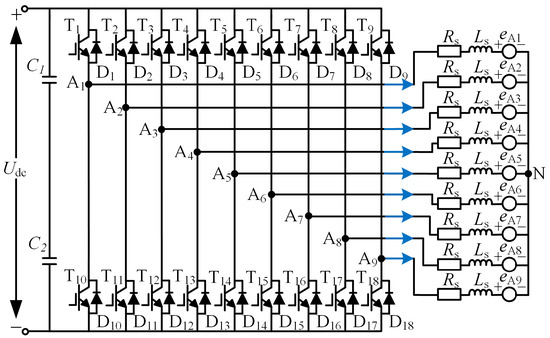
Figure 1.
The equivalent circuit diagram of a nine-phase brushless DC motor.
According to the equivalent circuit of the system shown in Figure 1, the voltage equation of the nine-phase BLDCM with symmetric winding can be expressed as
where uAi are the phase voltages, iAi are the phase currents, and uN is the neutral point voltage, i = 1, 2, …, 9.
The armature winding is a star connection. According to Kirchhoff’s current law, the phase currents satisfy the following relationship as
Equation (1) describes the relationship between the phase voltage, current, back electromotive force, and neutral point voltage of each phase winding. The expression for the neutral point voltage UN will be further derived in conjunction with the current constraint Equation (2) of the star shaped connection (see Equation (7)).
With the increase of the number of phases in the symmetrical winding multi-phase BLDCM, a larger flat top width of the back-EMF should be designed in order to make full use of each phase winding and achieve smooth output torque. Therefore, the trapezoidal wave back-EMF flat top width of the nine-phase BLDCM is usually designed to be 160°. In addition, the nine-phase BLDCM adopts the suspended one-phase conduction mode similar to the three-phase motor, so that the actual operation is carried out in the mode of eight-phase winding conduction. In this eight-phase conduction operation mode, the logical relationship between the back-EMF and the corresponding conduction phase current and the position signal is shown in Figure 2.
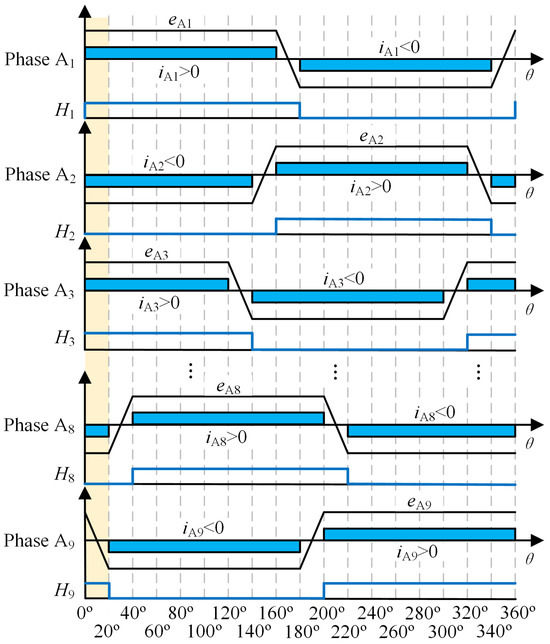
Figure 2.
The back-EMF and phase current in the eight-phase conduction mode of a nine-phase BLDCM.
It can be seen from Figure 2 that when the nine-phase BLDCM adopts the eight-phase winding conduction mode, the motor is controlled to commutation every 20° electrical angle according to the Hall signal feedback from the Hall effect sensor. The entire electrical cycle is divided into 18 sectors. Each sector opens four upper and four lower bridge arm switches simultaneously. The phase commutation process is carried out between the left and right bridge arms, and the ratio of positive and negative phase current is 1:1. The forward and reverse conduction angle of each phase armature winding is 160°, which corresponds to the flat top width of the back-EMF.
Similar to the principle in [9], where the three-phase BLDCM divides the Hall states into six operating sectors through the binary combination of Hall signals, for the nine-phase BLDCM, this paper extends this method to multi-phase applications, and the Hall states of the nine-phase BLDCM can also be expressed as
where the Hall state s corresponds to the current flow state of the motor. In the healthy state, assuming a clockwise direction, the Hall state s produces a repeat sequence 341→340→342→338→346→330→362→298→426→170→171→169→173→165→181→149→213→85→341. The Hall states 341 to 85, respectively, correspond to 18 sectors in the case of clockwise rotation of the motor, and the specific corresponding relationship is shown in Figure 3. The rotor position information is determined according to the Hall state s determined by nine Hall signals within a 360-degree electrical angle period, and then the conduction sequence and time of each phase of the motor are controlled.
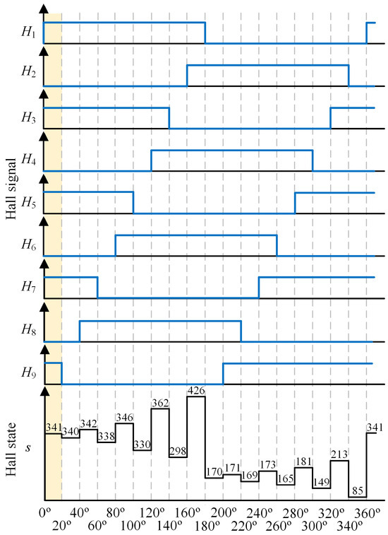
Figure 3.
Healthy state of 18 sectors’ Hall signals and their corresponding Hall state s.
As shown in the 0°~20° sector in the shaded part of Figure 2 and Figure 3, the corresponding Hall state is 341, and the corresponding conduction phase winding should be A1+, A2−, A3+, A4−, A5+, A6−, A7+, A8−, that is, A1, A3, A5, A7 phase winding positive guide pass, A2, A4, A6, A8 phase winding negative guide pass. A9 phase winding is a suspended phase. Finally, the corresponding Hall state and conducting phase winding relationship of each sector under clockwise rotation of the motor are obtained as shown in Table 1.

Table 1.
The corresponding Hall states and conduction phase windings for each sector when the motor rotates clockwise.
2.2. Fault Analysis of Position Sensors
In the event of Hall sensor failure—due to component damage, power loss, or disconnection of output lines—the detected Hall signal typically ceases to fluctuate in response to the rotor’s position. Instead, it becomes static, either “high” or “low”, devoid of any positional information regarding the rotor. Therefore, when the Hall sensor fails, according to its output signal Hi (i = 1, 2, …, 9) differences before and after the fault, the fault performance of the position sensor is divided into four types as shown in Figure 4. They are as follows: (1) Hi before and after the fault is low level, which is defined as low level fault 1; (2) Hi before the fault is high level, and Hi after the fault is low level, which is defined as low level fault 2; (3) Hi is high before and after the fault, which is defined as high level fault 1; (4) Hi is low level before the fault, but high level after the fault, which is defined as high level fault 2.
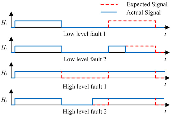
Figure 4.
Fault performance of position sensor.
As can be seen from Figure 4, the actual Hall signal in the fault state will deviate from the ideal Hall signal. At this point, sectors cannot be correctly determined based on the Hall state, which will lead to incorrect commutation. Therefore, the location of faults should be detected in a timely manner so that fault-tolerant control strategies can be adopted promptly.
3. Proposed Fault Diagnosis Method
3.1. Fault Diagnosis and Location
As can be seen from Figure 3, in the healthy state of the position sensor, the values of the Hall state obtained by the binary combination of the Hall signal are a fixed sequence. When the position sensor i malfunctions, it can be seen from the fault analysis in the first section that Hi is always 1 or 0. The incorrect Hall signal under the fault condition will definitely lead to values other than the fixed Hall state. Therefore, fault diagnosis can be made based on whether the Hall signal meets the Hall state value under a healthy state. The specific formula is as follows.
In the formula, hdet = 1 indicates that the position sensor is faulty, and hdet = 0 indicates that the sensor is normal. S is the set of normal Hall state values. When the value of Hall state s does not belong to the set S, it indicates that the position sensor is faulty. The expected Hall state value can be determined based on the value of the Hall state before the fault. Each expected Hall state value corresponds to a set of fixed Hall signals. Therefore, after determining the fault of the position sensor, the faulty position sensor can be located by judging the wrongly jumping Hall signal, as shown in the following formula
In the formula, hdeti = 1 indicates that the position sensor i is faulty, and hdeti = 0 indicates that the sensor i is normal. Hi and Hexpi represent the current and expected Hall signals, respectively.
The process of fault diagnosis and location of position sensor 1 through the Hall state timing table is shown in Figure 5a,b. Figure 5a and Figure 5b, respectively, show the schematic diagrams of diagnosis and location of low-level and high-level faults in Hall sensor 1. From the ideal Hall signal represented by the dotted line in the figure, it can be seen that in a healthy state, the Hall signal H1 should remain at a high level within the range of 0° to 180°, then switch from a high level to a low level at 180°, and then remain at a low level within the range of 180° to 360°, and so on in a cycle. Meanwhile, the value of the Hall state will also change according to the ideal state.
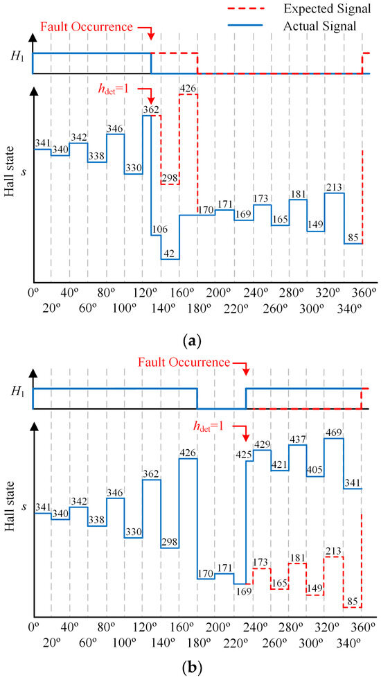
Figure 5.
Schematic diagram of fault diagnosis. (a) low level fault 2; (b) high level fault 2.
When the Hall sensor 1 experiences a low-level fault as shown in Figure 5a, the Hall signal H1 jumps to a low level in advance and remains unchanged. At this point, the originally expected Hall state value should have been 298, but the fault caused the Hall state s to mistakenly jump to 106. When the value of the fault detection flag hdet becomes 1, the fault can be diagnosed immediately. Then, based on the Hall signal combination corresponding to the Hall state value 362 being 101101010, and the current Hall signal combination constituting the Hall state 106 being 001101010, and comparing these two groups of Hall signals, it can be determined that the position sensor 1 corresponding to the Hall signal H1 has malfunctioned.
The high-level fault situation of Hall sensor 1 is shown in Figure 5b. Within the electrical angle range of 220° to 240°, the Hall signal H1 jumps to a high-level state in advance and remains unchanged. At this point, the originally expected Hall state value should be 173, but the fault caused the Hall states to mistakenly jump to 425, and the value of the fault detection marker hdet became 1, allowing the fault to be diagnosed immediately. Then, based on the Hall signal combination corresponding to the Hall state value 169 being 010101001, and the current Hall signal combination constituting the Hall state 425 being 110101001, and comparing these two groups of Hall signals, it can be located that the position sensor 1 corresponding to the Hall signal H1 has malfunctioned.
However, fault detection based on Hall signals may cause the error commutation time to be too long. As shown in Figure 6, the Hall signal H1 remains at a high level. Faults cannot be detected at 180°, and only the Hall state s value 427 can be detected at 200°, which does not match the expected 170. Therefore, in order to reduce the error commutation time, it is necessary to achieve fault detection in sectors ranging from 180 to 200° as much as possible. The expected Hall state is 170 within the 180° to 200° sector. In the case of a fault in position sensor 1, 426 remains unchanged, which will cause abnormal current phenomena in the multi-phase BLDCM. Therefore, the current conditions generated by the nine-phase BLDCM during the above-mentioned fault operation time are considered below to find the fault detection features.
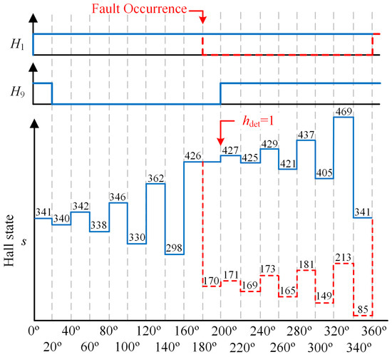
Figure 6.
Schematic diagram of fault diagnosis and location for high-level fault 1 of Hall sensor 1.
According to Table 1, during normal operation of nine-phase BLDCM, the conduction phase winding corresponding to Hall state 426 is A2+, A3−, A4+, A5−, A6+, A7−, A8+, A9−, and the conduction phase winding corresponding to Hall state 170 is A1−, A2+, A3−, A4+, A5−, A6+, A7−, A8+. In the fault condition shown in Figure 6, the A9 and A1 phase windings, which should have been commutated when the back electromotive force reached the boundary of the flat top width, will be delayed in commutation. At this time, the motor maintains A2, A4, A6, and A8 phase windings in the positive wizard state, and A3, A5, A7, and A9 phase windings in the negative wizard state. The winding conduction diagram under H_PWM-L_ON modulation strategy is shown in Figure 7.

Figure 7.
The system equivalent circuit during one PWM cycle when the eight-phase windings A2+, A3−, A4+, A5−, A6+, A7−, A8+, and A9− are conducting. (a) PWM = ON; (b) PWM = OFF.
Figure 7a and Figure 7b, respectively, show the current flow path when PWM = ON and PWM = OFF in one switching cycle of normal conduction cycle. It can be seen from Figure 7a that when PWM = ON, the current flows from the positive terminal of the power supply into phases A2, A4, A6, A8, and returns to the negative terminal of the power supply through phases A3, A5, A7, A9, forming a closed loop. A1 phase winding is a suspended phase, and no current passes through. At this time, the corresponding voltage equation of each phase winding terminal is
where iAp = −iAn, eAp = −eAn = E, p = 2, 4, 6, 8, n = 3, 5,7, eA9 ≠ E. The neutral point voltage uN can be obtained as
When the PWM modulation frequency is high, the carrier period is much smaller than the electromechanical time constant Ls/Rs, so the influence of winding resistance can be ignored. By substituting Equation (7) into Equation (6), the common terms in the equation can be eliminated, and the rate of change of A9 phase current during PWM conduction can be obtained:
This rate of change directly reflects the impact of back electromotive force on current dynamics (abnormal back electromotive force during faults can cause this rate of change to deviate from the normal range).
It can be seen from Figure 7b that when PWM = OFF, the current flows into the winding of phases A2, A4, A6, and A8 through the freewheeling diode, while the current flows out from the winding of phases A3, A5, A7, and A9 without passing through the negative electrode of the power supply, forming a closed loop. A1 phase winding is a suspended phase, and no current passes through. The corresponding voltage equation is
According to Equations (7) and (9), the current change rate of A9 phase winding can be obtained as
According to Equations (8) and (10), the average value of the current change rate of A9 phase winding in one PWM cycle can be obtained as
It can be seen from Equation (11) that since the dc bus voltage Udc and the equivalent phase inductance Ls are fixed values, the current change rate diA9/dt is mainly affected by the back-EMF eA9 and duty cycle D, providing a theoretical basis for subsequent fault diagnosis based on overcurrent characteristics. As shown in Figure 8a, in normal operation, eA9 = −E, diA9/dt = 0 under duty cycle D control, and phase current iA9 is maintained near the given current value iref. Since the amplitude of the back-EMF of A9 phase winding decreases after the fault, according to Equation (11), it can be obtained that diA9/dt < 0, the phase current iA9 of A9 phase winding continues to increase negatively, and the amplitude exceeds the given current value iref. Meanwhile, the phase current iA1 of A1 phase winding has iA1 = 0 due to delayed commutation.
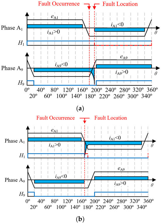
Figure 8.
Current variations resulting from fault operation angle and their corresponding back-EMF. (a) Delay commutation; (b) Advance commutation.
Similarly, it can be obtained through analysis that after low level fault 2 occurs in position sensor 1, Hall signal H1 jumps to low level in advance, A9 phase winding commutation to A1 phase winding in advance. At this time, A2, A4, A6, and A8 phase winding are in positive conduction state, A1, A3, A5, and A7 phase windings are in negative conduction state, and the change rate of phase current iA1 of A1 phase winding is
in the equation, since the back-EMF eA1 of phase A1 has not reached its peak value E, it follows that diA1/dt < 0. The amplitude of the phase current iA1 continues to increase beyond the reference current value iref. Meanwhile, the phase current iA9 of phase A9 is zero because of the advance commutation. The back-EMF and current change situation at this time is shown in Figure 8b.
The aforementioned analysis results of current fault characteristics can be utilized to accurately reflect the fault conditions of multi-phase BLDC under multi-phase conduction modes. Figure 9a,b illustrate the current conditions of the windings in the eight-phase conduction mode corresponding to Hall state 426, under normal conditions and delayed commutation due to a fault in the position sensor 1, respectively. According to the phase currents relation Equation (2) of the star connection, the sum of the positive guide current and the negative guide current should be zero. However, the fault leads to an increase in the amplitude of phase current iA9, which results in a decrease in current for the negatively conducting phases A3, A5, and A7 that are in the same conduction group as phase A9, while the current for the positively conducting phases A2, A4, A6, and A8 increases. Since the current changes in other phases are average, the change of phase current iA9 is particularly significant. At the same time, its phase current iA1 is zero because the phase A1 winding is not conducted. These variations allow us to precisely locate the fault location sensors.
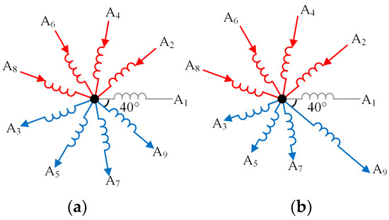
Figure 9.
Current situation in each phase winding under the eight-phase conduction mode corresponding to Hall state 426. (a) Normal state; (b) Delayed commutation state.
In conclusion, if the Hall sensor 1 fails and is not diagnosed in time and a fault-tolerant control strategy is not adopted, obvious fault current characteristics will appear, which can be used as fault detection features. Therefore, the idet1 judgment marker for Hall sensor 1 to diagnose faults based on fault current characteristics is defined as follows
In the formula, idet1 = 1 indicates that the Hall sensor 1 exhibits current characteristics, and ith is a preset fixed value, which is determined based on the given reference current iref of the system and the expected normal operating current fluctuation range (current ripple). Specifically, ith = k·iref. In this experiment, k is taken as 1.4. εA is also a current threshold, which is set based on the noise characteristics of the current sampling system (including sensor noise, zero drift, ADC quantization error). To avoid misdiagnosis, its value should be greater than the maximum value of the sampling error. iothers indicates the phase currents other than iA1 and iA9.
Specifically, the value of the constant k needs to be determined based on experiments on current ripple characteristics during the normal operation of the motor: its value is based on experiments on normal current fluctuation characteristics under full operating conditions (including steady state, acceleration, deceleration, loading, and unloading processes) of the nine-phase BLDCM, statistically obtaining the ratio of the maximum peak value of current ripple to the reference current iref. To cover such fluctuations and reserve a safety margin to prevent misjudgment, k is finally set to 1.4, ensuring that ith = k·iref can reliably distinguish between normal ripples and fault over currents. Full operating condition experiments show that the threshold corresponding to this fixed k value can cover the current ripple range under all normal operating states of the motor. In contrast, the peak values of current anomalies caused by position sensor faults (such as aperiodic over currents resulting from commutation delay or advance) are far beyond this range. The two are significantly different, so they can be effectively distinguished without dynamic adjustment. Meanwhile, the original design intention of this method is “no need for complex calculations” to meet the real-time diagnosis requirements of multi-phase motors. If a dynamic adjustment strategy is adopted, additional algorithms such as working condition identification and ripple prediction need to be introduced, which will increase computational complexity and contradict the advantages of this method. Experimental verification also shows that fixing k = 1.4 can still quickly and accurately diagnose faults under dynamic working conditions without missed judgments or misjudgments.
The determination of the noise threshold εA is based on the noise characteristics of the current sampling system: under the condition where the motor is shut down and only the sampling circuit is powered on, the output signal of the sampling circuit is collected, and the maximum peak-to-peak value of the noise signal is calculated. Subsequently, εA is set to 1.5 times this peak-to-peak value to effectively filter out the interference of sampling noise on fault judgment. It is worth noting that high temperatures may cause zero drift and increased noise in the current sampling system; however, the value of εA has fully covered the maximum sampling errors in high-temperature environments (including sensor temperature drift, ADC quantization error, etc.), which can prevent misjudgments caused by noise induced by high temperatures.
Combined with the dual judgment mechanism of “abnormal Hall state and abnormal current characteristics”, this threshold can further filter out single-dimensional abnormal interference (such as only abnormal current signals or only abnormal position signals), thereby ensuring reliable diagnosis and fault-tolerant control even under the influence of variables like high temperature and short circuit.
By conducting the above derivation process for the fault conditions of other Hall sensors, the corresponding fault detection marks of each Hall sensor can be obtained as shown in Table 2, where i represents the label of the Hall position sensor, and i = {1, 2, 3, … n}, where n represents the total number of Hall position sensors. Based on the current characteristics in the table, the faults of the Hall position sensors corresponding to the labels can be determined.

Table 2.
The determination sign based on current characteristic of Hall position sensor in fault state.
In summary, the position sensor fault location marker Fi obtained based on the Hall signal timing table and fault detection based on current characteristics is defined as follows
In the formula, Fi = 1, indicating that the Hall position sensor labeled i is faulty; Fi = 0 indicates that the ith Hall position sensor is normal.
3.2. Fault-Tolerant Control
After diagnosing a faulty Hall sensor, the Hall signal should be reconstructed immediately to achieve the fastest recovery of motor operation. A suitable solution is to establish the reconstructed signal (as a backup Hall signal) before the potential fault, and once the fault is diagnosed, the reconstructed signal obtained from the normal Hall signal can be used to replace the faulty Hall signal immediately. Because multi-phase BLDCM requires higher rotor position detection accuracy, the fault-tolerant control method adopted is to obtain a continuous rotor position through healthy Hall signal, and then reconstruct the Hall signal according to the angle corresponding to the fault Hall signal.
The rotational speed of the nine-phase BLDCM can be obtained in the following way
where ω is the mechanical angular speed of the motor and p is the number of rotor poles of the nine-phase motor, which is equal to 2 in the nine-phase BLDCM; γ is the average count between the adjacent rising edges of the nine position pulse signals, denoted by
where {i∣i = 1, 2, …, 9} is the number of nine Hall position signals; fi is the fault symbol of the ith Hall sensor, where fi = 1 in the normal case and fi = 0 in the fault case; γi is the calculated value between the adjacent rising edges of the ith Hall signal.
The angle is calculated by the formula
where θt is the rotor position at time t and θt−1 is the angle of the adjacent last Hall signal jump along the corresponding rotor position at time t. Based on Equations (15)–(17), as long as one position sensor is normal, the rotor position can be calculated, and then the reconstructed Hall signal can be obtained.
The summary of the fault-tolerant control operation process is as follows: ① Speed calculation: Based on the adjacent transition edge interval of the healthy Hall signal, calculate the mechanical angular velocity ω of the motor through Equations (15) and (16); ② Rotor position estimation: Using the rotor position θt−1 corresponding to the previous Hall signal, combined with the speed ω and time interval, calculate the current rotor position θt in real time; ③ Fault Hall Signal Reconstruction: Based on the estimated θt, match its corresponding normal Hall state (Table 1), reconstruct the Hall signal of the fault sensor, and replace the fault signal to participate in commutation control.
The motor control flow chart after adopting the proposed fault diagnosis method is shown in Figure 10. When the Hall signal is obtained according to the Hall position sensor during the operation of nine-phase BLDCM, the fault is first diagnosed by the fault diagnosis and fault-tolerant control module to ensure the correct position of the motor. Then the signal passes through the speed controller and the current controller after generating the duty D through the PWM signal generator control inverter to achieve accurate control of motor.
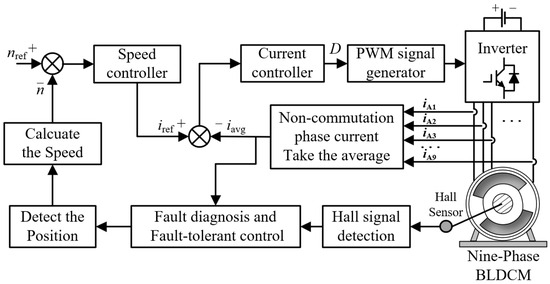
Figure 10.
Schematic diagram of the proposed fault diagnosis control method.
4. Experimental Results and Analysis
To verify the correctness of the theoretical analysis, this paper constructs a nine-phase BLDCM drive system as an experimental platform, as shown in Figure 11. The control circuit adopts DSP (TMS320F28335) and FPGA (EP1C6Q240C8) as the central control unit. The sampling frequency of the position signal (Hall signal) and stator current signal involved in fault detection in this experiment is 10 kHz. This sampling frequency can meet the requirements of capturing Hall signal transitions and fault current characteristics. In terms of the sampling circuit, the LEM voltage sensor (LV25-P) is selected to sample the DC bus voltage, and the LEM current sensor (LAH50-P) is adopted simultaneously to sample the phase current. The motor is loaded by using the MAGTROL hysteresis brake (AHB-12), and the torque sensor (TM307) is used to measure the actual motor torque. During the experiment, the Hall signal fault was simulated through the switch, and the Hall signal used by the controller was set to a constant value. The experimental results were recorded using a Yokogawa eight-channel digital oscilloscope (model DLM4058).
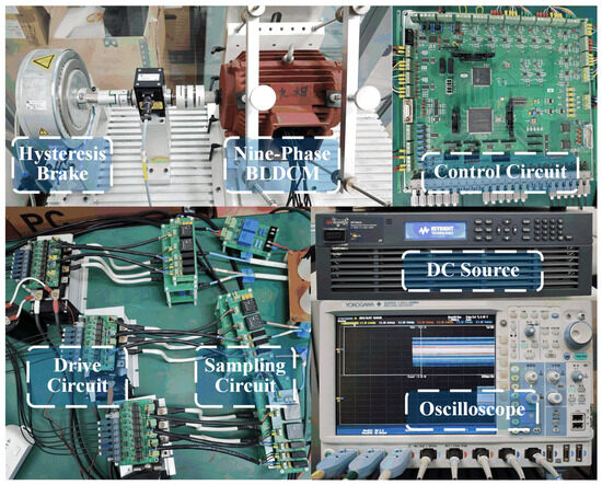
Figure 11.
Experimental prototype.
The motor used in this experiment is a symmetrical winding nine-phase BLDCM, and its specific parameters are listed in Table 3.

Table 3.
Motor parameters.
4.1. Steady-State Experiments
(1) Single position sensor fault: Since the fault diagnosis process of each Hall position sensor is the same, the fault of position sensor 1 is taken as an example for experimental verification in the following.
Figure 12 and Figure 13 shows the position signal H1 of position sensor 1 under four fault conditions, the position signals H2 and H9 of adjacent two-phase position sensors, the corresponding three-phase currents iA1, iA2, iA9, the fault location mark F1, and the speed n of position sensor 1 under steady-state conditions. Where n and load are set to 1000 r/min and 4 N·m, respectively.
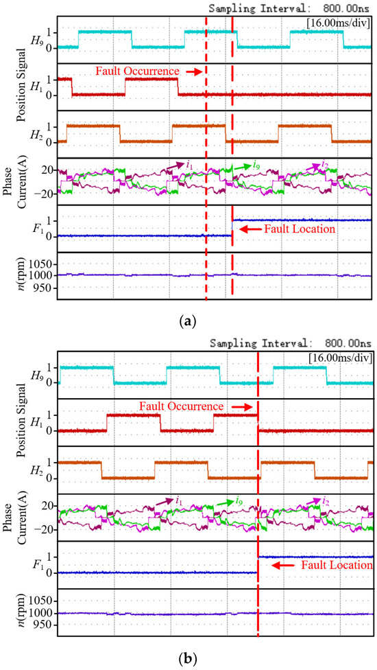
Figure 12.
Experimental results of position sensor 1 with low level fault. (a) low level fault 1; (b) low level fault 2.
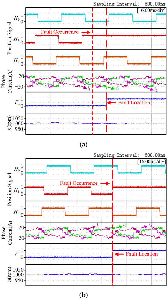
Figure 13.
Experimental results of position sensor 1 with high level fault. (a) high level fault 1; (b) high level fault 2.
Figure 12a shows the experimental results when the position sensor 1 has a low-level fault 1. As can be seen from the figure, after the fault occurs, the position signal H1 remains at a low level, causing the A9 phase winding to fail to commutate correctly, and the phase current iA9 remains on continuously. At the same time, the phase current iA1 of the A1 phase winding is delayed in being turned on. At this time, due to the decrease in the opposite electromotive force of the A9 phase, the phase current iA9 suddenly increases. The current fault feature idet1 of position sensor 1 satisfies |iA9| > iref, and the current value of iA1 is zero at the same time. At this point, the fault is immediately diagnosed. The key point of this experiment is to verify the effectiveness of the proposed diagnostic method. Therefore, after diagnosing the fault situation, the normal Hall signal was restored immediately, so the subsequent operation of the motor was not affected. Figure 12b shows the experimental results when the position sensor 1 experiences a low-level fault 2. The Hall signal H1 jumps from a high-level state to a low-level state in advance. At this time, the expected Hall state does not match the actual Hall state, and the fault of the position sensor can be quickly diagnosed and located according to the Hall state timing table.
The experimental results when the position sensor 1 experiences a high-level fault 1 are shown in Figure 13a. At this time, the Hall signal H1 of the position sensor 1 remains at a high level, similar to the situation when it remains at a low level during a low-level fault 1. Due to the fault, the A9 phase winding cannot be commutated correctly, and the phase current iA9 remains conducting continuously. At the same time, the phase current iA1 of the A1 phase winding is delayed in opening, and the phase current iA9 suddenly increases. The current fault characteristic idet1 of the position sensor 1 satisfies |iA9| > iref, and the current value of iA1 is zero at the same time. At this point, the fault is immediately diagnosed. Figure 13b shows the experimental results when the position sensor 1 has a high-level fault 2. The position signal H1 jumps in advance, and the fault of the position sensor can be quickly diagnosed and located according to the Hall state timing table.
(2) Two position sensor faults: Since nine Hall position sensors are needed for the nine-phase BLDCM to obtain the corresponding rotor position, the following two adjacent position sensors 1 and 2 and two non-adjacent position sensors 1 and 6 faults are taken as examples for experimental verification.
Figure 14 shows the experimental diagram of the diagnosis process for the simultaneous failure of position sensors 1 and 2. From top to bottom in the figure are Hall signals H1 and H2, phase currents iA1, iA2 and iA9, and the fault location markers F1 and F2 of position sensors 1 and 2. The rotational speed and load are set to 800 r/min and 2 N·m, respectively. As shown in Figure 14, position sensors 1 and 2 malfunctioned at the same time, with high-level faults 2 and low-level faults 2 occurring, respectively. Due to the premature jump of their level states, the expected Hall state was inconsistent with the actual Hall state. Based on the Hall state timing table, the faults of these two position sensors were quickly diagnosed and located.
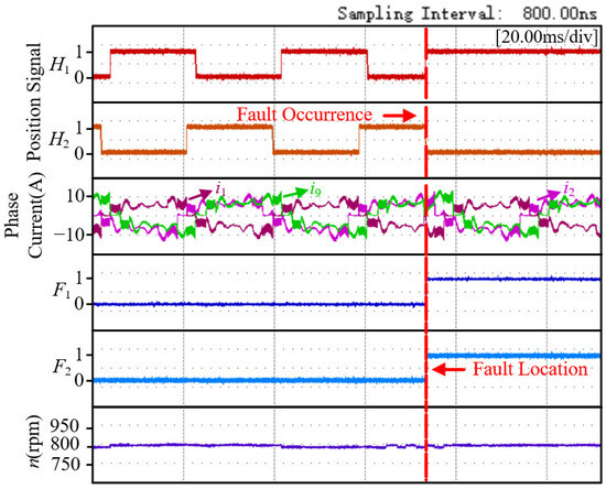
Figure 14.
Experimental results for position sensor 1 with high level fault 2 and position sensor 2 with low level fault 2.
Another fault situation of the two position sensors is shown in Figure 15. Although faults occurred simultaneously, the fault conditions at this time were as follows: position sensor 1 had a low-level fault 1, and position sensor 6 had a high-level fault 2. The fault situation of position sensor 6 was quickly diagnosed and the fault of the position signal was located. However, after the failure of position sensor 1, the fault signal was the same as the expected signal. Therefore, the fault could only be diagnosed immediately when the current fault characteristic idet1 was satisfied |iA9| > iref and the current value of iA1 was zero. But due to the rapid change of current, the fault was diagnosed immediately before serious consequences occurred. It is conducive to switch to the fault-tolerant control strategy in a timely manner according to the corresponding fault situation.
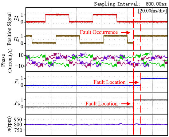
Figure 15.
Experimental results for position sensor 1 with low level fault 1 and position sensor 6 with high level fault 2.
4.2. Dynamic Experiments
In order to verify the effectiveness of the proposed method under dynamic conditions, fault diagnosis experiments were carried out for the position sensor under four working conditions of acceleration, deceleration, loading, and load shedding.
Experimental results for position sensor 1 failures during acceleration, deceleration, loading, and load shedding are shown in Figure 16, Figure 17, Figure 18 and Figure 19, where the blue arrow points to a magnified view of the dashed box (magnified on the timeline only). According to the enlarged plot of the dashed box, it can be seen that based on the proposed fault diagnosis method, fault detection and localization can also be achieved under dynamic conditions.
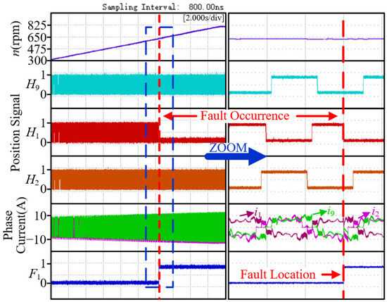
Figure 16.
Experimental results for position sensor 1 with low level fault 2 during acceleration.
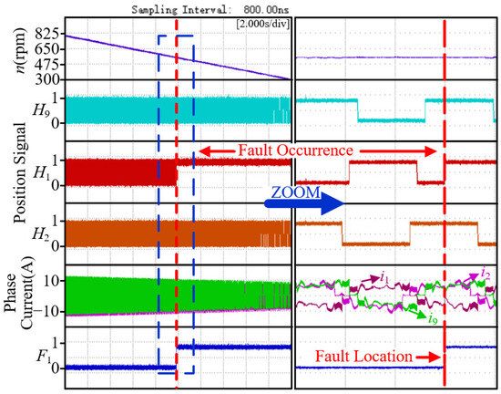
Figure 17.
Experimental results for position sensor 1 with high level fault 2 during deceleration.
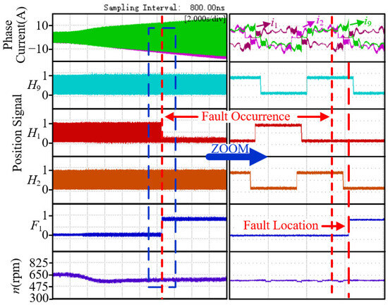
Figure 18.
Experimental results for position sensor 1 with low level fault 1 during loading.
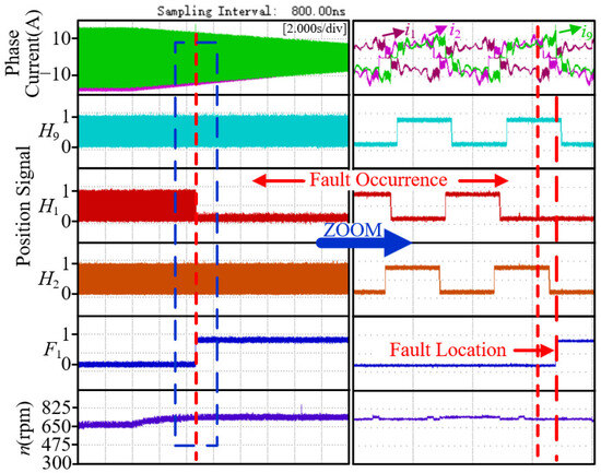
Figure 19.
Experimental results for position sensor 1 with low level fault 1 during load reduction.
Figure 16 shows the experimental results of a low-level fault 2 in position sensor 1 under acceleration conditions. When the motor accelerates from 300 to 800 r/min, the H1 signal jumps to a low level in advance, and the fault diagnosis flag F1 is quickly triggered and the fault is accurately located. Figure 17 shows the experimental results of high-level fault 2 in position sensor 1 under deceleration conditions. During the deceleration of the motor from 800 to 300 r/min, the H1 signal jumps to high level in advance, and the diagnostic flag is also triggered quickly.
The two sets of experiments jointly demonstrate that in dynamic variable speed scenarios, the proposed method can achieve reliable fault detection through the collaborative diagnostic mechanism of Hall signal anomalies and current characteristic mutations, verifying its stability and effectiveness in acceleration/deceleration processes.
Figure 18 clearly shows the experimental results of low-level fault 1 of position sensor 1 under loading conditions. As the load increases, the amplitude of the phase current increases; after the fault occurred, due to a commutation logic error, the phase current iA9 exceeded the threshold ith, and the fault location indicator F1 was quickly triggered, verifying the sensitive capture ability of the method for faults under loading conditions. Figure 19 shows the experimental results of low-level fault 1 of position sensor 1 under reduced load conditions. When the load decreases, the phase current iA9 still exceeds the threshold ith after the fault, and the F1 flag can still respond quickly.
The two sets of experiments jointly demonstrate that in the scenario of sudden load changes, the proposed method can achieve reliable and rapid detection of position sensor faults through the abnormal over limit characteristics of phase currents and fault localization logic, verifying its adaptability and robustness to load variation conditions.
4.3. Performance Analysis of Fault Detection
Our existing steady-state and dynamic experimental results (Figure 12, Figure 13, Figure 14, Figure 15, Figure 16, Figure 17, Figure 18 and Figure 19) contain precise time information captured by the oscilloscope (switch action time and Fi jump time of manually simulated faults). We will systematically reanalyze all experimental waveform diagrams and accurately measure the time difference between the switch action time and the Fi jump time of manually simulated faults. The motor runs for a long time under healthy conditions, records the output status of Fi, and counts the number of false alarms.
Based on the preliminary analysis of existing experimental data, the statistical results are as follows:
Steady-state condition: When a low-level fault occurs, due to the limitation of current rise time, the average detection delay is 128 μs; when a low-level fault occurs, the average detection delay is 89 μs; when high-level fault 1 occurs, due to the limitation of current drop time, the average detection delay is 135 μs; when high-level fault 2 occurs, the average detection delay is 93 μs; when adjacent sensors (H1 and H2) fail, the average detection delay is 115 μs; when non adjacent sensors (H1 and H6) fail, the average detection delay is 123 μs. Overall, the average detection delay under steady-state conditions is 114 μs, which is much smaller than the motor commutation interval (the time for a 20° electrical angle commutation interval of the motor at 2500 r/min is about 667 μs).
Dynamic operating conditions: The motor accelerates from 300 to 800 r/min with an average detection delay of 113 μs; decelerates from 800 to 300 r/min, with an average detection delay of 128 μs; the average detection delay under loading conditions is 125 μs, and the average detection delay under unloading conditions is 137 μs. In summary, the average detection delay under dynamic operating conditions is 125 μs, which is also much smaller than the motor commutation cycle, ensuring that the diagnosis is completed before the next commutation, avoiding the accumulation of erroneous commutation, and verifying the speed of the method in real-time diagnosis.
The motor operates for a long time under healthy conditions, with zero false alarms. Due to the fact that Fi needs to satisfy both Hall state anomaly (hdeti = 1) and current characteristic anomaly (ideti = 1), the dual criteria effectively avoid false alarms caused by single signal noise (such as current sampling noise and Hall signal glitches).
Through quantitative statistics in Table 4, it can be intuitively demonstrated that the detection delay of the proposed method remains stable and fast under different fault types and operating conditions, meeting the real-time diagnosis requirements of multi-phase BLDCM. The extremely low false alarm rate ensures that the method will not interfere with normal operation, enhancing the feasibility of engineering applications.

Table 4.
Fault detection performance statistics.
4.4. Construction of the Actual Rotor Position Angle Under Fault-Tolerant Conditions
In order to verify the feasibility of the fault-tolerant operation, experiments are carried out on the single sensor fault and the double position sensor fault, where the single sensor fault takes the position sensor 1 fault as an example, as shown in Figure 20a. The faults of the two position sensors are the faults of position sensor 1 and position sensor 2, and the faults of position sensor 1 and position sensor 6, as shown in Figure 20b and Figure 20c, respectively. Figure 20 shows that the actual rotor position angle θ can be constructed under fault-tolerant control.
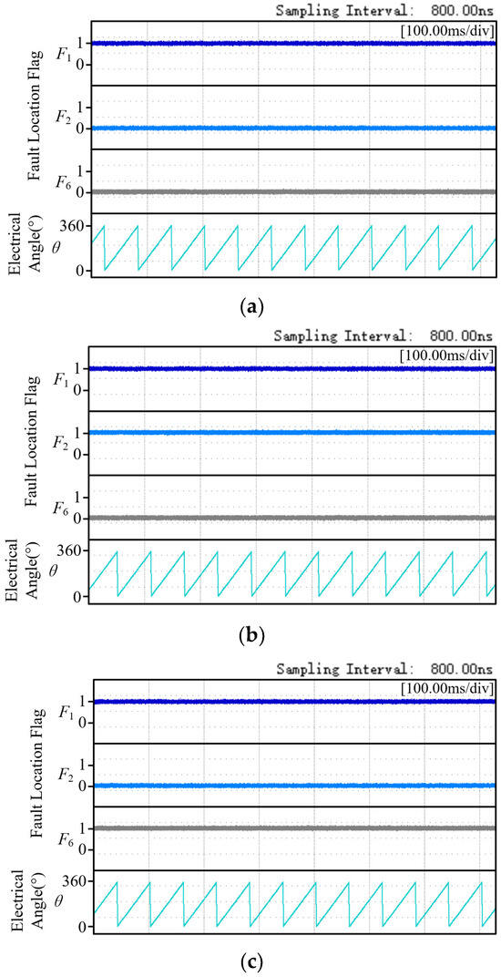
Figure 20.
Fault-tolerant experimental results for position sensor. (a) Position sensor 1 fault; (b) Both position sensor 1 and position sensor 2 fault; (c) Both position sensor 1 and position sensor 6 fault.
As shown in Figure 20, the experimental results of fault-tolerant control of position sensor are presented in Figure 20a, which shows the fault-tolerant performance of position sensor 1 after failure. Figure 20b shows the fault-tolerant results after both position sensor 1 and position sensor 2 have faults. Figure 20c is the fault-tolerant result after both position sensor 1 and position sensor 6 have faults. As shown in Figure 20, regardless of whether there is a single sensor fault or a dual sensor (adjacent/non adjacent) fault, the proposed fault-tolerant control method can accurately reconstruct the actual rotor position angle, providing a key guarantee for the continuous and stable operation of the motor.
5. Conclusions
Aiming at the fault problem of Hall position sensors in multi-phase brushless DC motors, taking the nine-phase BLDCM as the research object, a fault diagnosis method based on fault current characteristics is proposed. This method first conducts a preliminary diagnosis by using the preset Hall state values, and quickly identifies faults by comparing the sequence characteristics of the Hall signals. In order to further improve the diagnostic efficiency, the current characteristics after the fault were analyzed, and the fault location was achieved based on the fault current characteristics. Ultimately, by integrating the position signal and current characteristics, the precise positioning of the fault location sensor was achieved. The main contributions of the proposed method are as follows.
(1) The proposed method does not require additional detection devices, but can be applied to dynamic conditions, which is helpful to reduce the cost of the system and broaden the application range of the diagnosis method.
(2) For the first time, a position sensor fault diagnosis method based on existing position signals and phase currents is proposed for the nine-phase BLDCM, which can realize independent and fast fault diagnosis for each position sensor, and help to switch to the fault-tolerant strategy in time to minimize the impact of faults on system performance.
(3) The method proposed in this paper has wide applicability. It can be adapted to a variety of multi-phase BLDCM systems using Hall sensors. Combined with the method presented in this paper, the control reliability of multi-phase BLDCM can be significantly improved to ensure the stable operation of the system.
Author Contributions
Conceptualization, W.C. and X.L.; methodology, J.L. and W.Z.; software, J.L. and S.Z.; validation, J.L., S.Z. and X.L.; formal analysis, W.C.; investigation, S.Z.; resources, W.Z.; data curation, S.Z.; writing—original draft preparation, S.Z.; writing—review and editing, J.L., W.C. and X.L.; supervision, W.C.; project administration, W.C.; funding acquisition, W.C. All authors have read and agreed to the published version of the manuscript.
Funding
This research was funded by the National Key Research and Development Project of China under Grant 2024YFB2505102, the Joint Fund Key Project of the National Natural Science Foundation of China under Grant U23A20643, and the Key Program of Tianjin Natural Science Foundation under Grant 24JCZDJC00250.
Data Availability Statement
The original contributions presented in this study are included in the article; further inquiries can be directed to the corresponding author.
Conflicts of Interest
Author Wei Zhang is an employee of CATARC New Energy Vehicle Test Center (Tianjin) Co., Ltd. The remaining authors declare that the research was conducted in the absence of any commercial or financial relationships that could be construed as a potential conflict of interest.
References
- Kirtley, J.-L.; Banerjee, A.; Englebretson, S. Motors for Ship Propulsion. Proc. IEEE 2015, 103, 2320–2332. [Google Scholar] [CrossRef]
- Schefer, H.; Fauth, L.; Kopp, T.-H.; Mallwitz, R.; Friebe, J.; Kurrat, M. Discussion on Electric Power Supply Systems for All Electric Aircraft. IEEE Access 2020, 8, 84188–84216. [Google Scholar] [CrossRef]
- Chau, K.-T.; Chan, C.-C.; Liu, C.-H. Overview of Permanent-Magnet Brushless Drives for Electric and Hybrid Electric Vehicles. IEEE Trans. Ind. Electron. 2008, 55, 2246–2257. [Google Scholar] [CrossRef]
- Wang, M.-Q.; Zheng, P.; Tong, C.-D.; Zhao, Q.-B.; Qiao, G.-Y. Research on a Transverse-Flux Brushless Double-Rotor Machine for Hybrid Electric Vehicles. IEEE Trans. Ind. Electron. 2019, 66, 1032–1043. [Google Scholar] [CrossRef]
- Sulligoi, G.; Vicenzutti, A.; Menis, R. All-Electric Ship Design: From Electrical Propulsion to Integrated Electrical and Electronic Power Systems. IEEE Trans. Transp. Electrif. 2016, 2, 507–521. [Google Scholar] [CrossRef]
- Chen, W.; Zhu, L.-X.; Li, X.-M.; Shi, T.-N.; Xia, C.-L. Comparing the Performance of Parallel Multi-Phase Brushless DC Motors: A Comprehensive Analysis. IEEE Trans. Power Electron. 2023, 38, 11290–11303. [Google Scholar] [CrossRef]
- Zhu, L.-X.; Chen, W.; Li, X.-M.; Wang, Z.-Q. Fault-Tolerant Control Method to Reduce Torque Ripple for Symmetrical Winding Multi-Phase Brushless DC Motor Under Open-Circuit Faults. In Proceedings of the 2024 27th International Conference on Electrical Machines and Systems (ICEMS), Fukuoka, Japan, 26–29 November 2024; pp. 679–685. [Google Scholar] [CrossRef]
- Dong, L.; Jatskevich, J.; Huang, Y.; Chapariha, M.; Liu, J. Fault diagnosis and signal reconstruction of hall sensors in brushless permanent magnet motor drives. IEEE Trans. Energy Convers. 2016, 31, 118–131. [Google Scholar] [CrossRef]
- Ebadpour, M.; Amiri, N.; Jatskevich, J. Fast fault-tolerant control for improved dynamic performance of hall-sensor-controlled brushless DC motor drives. IEEE Trans. Power Electron. 2021, 36, 14051–14061. [Google Scholar] [CrossRef]
- Ofori, E.; Husain, T.; Sozer, Y.; Husain, I. A pulse-injection-based sensorless position estimation method for a switched reluctance machine over a wide speed range. IEEE Trans. Ind. Appl. 2015, 51, 3867–3876. [Google Scholar] [CrossRef]
- Cai, J.; Deng, Z. Initial rotor position estimation and sensorless control of SRM based on coordinate transformation. IEEE Trans. Instrum. Meas. 2015, 64, 1004–1018. [Google Scholar] [CrossRef]
- Chen, W.; Zhu, L.; Wang, S.; Li, X.; Shi, T.; Xia, C. Rotating Restart Method for TPFS Inverter-Fed Sensorless PMSM Drive System Based on Dual Effective Voltage Vectors Injection. IEEE Trans. Power Electron. 2024, 39, 11708–11722. [Google Scholar] [CrossRef]
- Chen, W.; Dong, S.-H.; Li, X.-M.; Cao, Y.-F.; Zhang, G.-Z. Initial Rotor Position Detection for Brushless DC Motors Based on Coupling Injection of High-Frequency Signal. IEEE Access 2019, 7, 133433–133441. [Google Scholar] [CrossRef]
- Lyons, J.P.; Macminn, S.R.; Preston, M.A. Flux-current methods for SRM rotor position estimation. In Proceedings of the Conference Record of the 1991 IEEE Industry Applications Society Annual Meeting, Dearborn, MI, USA, 28 September–4 October 1991; pp. 482–487. [Google Scholar]
- Song, S.; Ge, L.; Zhang, Z. Accurate position estimation of SRM based on optimal interval selection and linear regression analysis. IEEE Trans. Ind. Electron. 2016, 63, 3467–3478. [Google Scholar] [CrossRef]
- Lee, Y.; Sul, S.-K. Model-Based Sensorless Control of an IPMSM With Enhanced Robustness Against Load Disturbances Based on Position and Speed Estimator Using a Speed Error. IEEE Trans. Ind. Appl. 2018, 54, 1448–1459. [Google Scholar] [CrossRef]
- de Araujo Porto Henriques, L.O.; Rolim, L.G.B.; Suemitsu, W.I.; Dente, J.A.; Costa Branco, P.J. Development and experimental tests of a simple neurofuzzy learning sensorless approach for switched reluctance motors. IEEE Trans. Power Electron. 2011, 26, 3330–3344. [Google Scholar] [CrossRef]
- Cai, Y.; Wang, Y.; Xu, H.; Sun, S.; Wang, C.; Sun, L. Research on rotor position model for switched reluctance motor using neural network. IEEE/ASME Trans. Mechatron. 2018, 23, 2762–2773. [Google Scholar] [CrossRef]
- Saha, B.; Singh, B.; Sen, A. SMO Based Position Sensorless BLDC Motor Drive Employing Canonical Switching Cell Converter for Light Electric Vehicle. IEEE Trans. Ind. Appl. 2023, 59, 2974–2984. [Google Scholar] [CrossRef]
- Chen, Z.; Tomita, M.; Doki, S.; Okuma, S. New adaptive sliding observers for position- and velocity-sensorless controls of brushless DC motors. IEEE Trans. Ind. Electron. 2000, 47, 582–591. [Google Scholar] [CrossRef]
- Tomita, M.; Senjyu, T.; Doki, S.; Okuma, S. New sensorless control for brushless DC motors using disturbance observers and adaptive velocity estimations. IEEE Trans. Ind. Electron. 1998, 45, 274–282. [Google Scholar] [CrossRef]
- Ding, W.; Song, K. Position sensorless control of switched reluctance motors using reference and virtual flux linkage with one-phase current sensor in medium and high speed. IEEE Trans. Ind. Electron. 2020, 67, 2595–2606. [Google Scholar] [CrossRef]
- Chen, W.; Liu, Z.; Cao, Y.-F.; Li, X.-M.; Shi, T.-N.; Xia, C.-L. A Position Sensorless Control Strategy for the BLDCM Based on a Flux-Linkage Function. IEEE Trans. Ind. Electron. 2019, 66, 2570–2579. [Google Scholar] [CrossRef]
- Chen, S.; Liu, G.; Zhu, L. Sensorless Control Strategy of a 315 kW High-Speed BLDC Motor Based on a Speed-Independent Flux Linkage Function. IEEE Trans. Ind. Electron. 2017, 64, 8607–8617. [Google Scholar] [CrossRef]
- Song, X.; Han, B.; Wang, K. Sensorless Drive of High-Speed BLDC Motors Based on Virtual Third-Harmonic Back EMF and High-Precision Compensation. IEEE Trans. Power Electron. 2019, 34, 8787–8796. [Google Scholar] [CrossRef]
- Cai, J.; Deng, Z. A joint feature position detection-based sensorless position estimation scheme for switched reluctance motors. IEEE Trans. Ind. Electron. 2017, 64, 4352–4360. [Google Scholar] [CrossRef]
- Champa, P.; Somsiri, P.; Wipasuramonton, P.; Nakmahachalasint, P. Initial Rotor Position Estimation for Sensorless Brushless DC Drives. IEEE Trans. Ind. Appl. 2009, 45, 1318–1324. [Google Scholar] [CrossRef]
- Cai, J.; Deng, Z.Q. An approach to selecting the optimal sensing coil configuration structure for switched reluctance motor rotor position measurement. Rev. Sci. Instrum. 2015, 86, 025002. [Google Scholar] [CrossRef]
- Li, X.-M.; Li, X.-C.; Chen, W.; Liu, K.; Wang, Z.-Q. Rotor Position Detection of IPMSM Based on Search Coil in Full-Speed Range. IEEE Trans. Power Electron. 2025, 40, 14571–14584. [Google Scholar] [CrossRef]
- Li, X.-M.; Li, X.-C.; Liu, X.; Guo, L.-Y.; Wang, J.; Wang, Z.-Q.; Chen, W. An Uncoupled Search Coil for IPMSM Rotor Position Detection in Low-Speed Range. IEEE Trans. Transp. Electrif. 2025, 11, 7527–7541. [Google Scholar] [CrossRef]
- Rahimi, T.; Ding, L.; Peyghami, S.; Kheshti, M.; Blaabjerg, F.; Davari, P. Time Domain Simulation of A Five-Phase BLDC Motor Drive. In Proceedings of the 2020 11th Power Electronics, Drive Systems and Technologies Conference (PEDSTC), Tehran, Iran, 4–6 February 2020; pp. 1–6. [Google Scholar] [CrossRef]
- Dong, L.-H.; Huang, Y.-W.; Jatskevich, J.; Liu, J.-L. Improved fault-tolerant control for brushless permanent magnet motor drives with defective Hall sensors. IEEE Trans. Energy Convers. 2016, 31, 789–799. [Google Scholar] [CrossRef]
- Cai, J.; Zhao, X. Synthetic hybrid-integral-threshold logic-based position fault diagnosis scheme for SRM drives. IEEE Trans. Instrum. Meas. 2021, 70, 1–8. [Google Scholar] [CrossRef]
- Balaban, E.; Saxena, A.; Bansal, P.; Goebel, K.; Curran, S. Modeling, detection, and disambiguation of sensor faults for aerospace applications. IEEE Sens. J. 2009, 9, 1907–1917. [Google Scholar] [CrossRef]
- Hong, S.K.; Lee, Y. Optimizing Detection: Compact MobileNet Models for Precise Hall Sensor Fault Identification in BLDC Motor Drives. IEEE Access 2024, 12, 77475–77485. [Google Scholar] [CrossRef]
- Kao, I.-H.; Wang, W.-J.; Lai, Y.-H.; Perng, J.-W. Analysis of Permanent Magnet Synchronous Motor Fault Diagnosis Based on Learning. IEEE Trans. Instrum. Meas. 2018, 68, 310–324. [Google Scholar] [CrossRef]
- Kerboua, A.; Kelaiaia, R. Fault diagnosis in an asynchronous motor using three-dimensional convolutional neural network. Arab. J. Sci. Eng. 2024, 49, 3467–3485. [Google Scholar] [CrossRef]
- Chu, K.S.K.; Chew, K.W.; Chang, Y.C. Fault Diagnosis System of Hall Sensor in Brushless DC Motor Based on Neural Networks Approach. In Proceedings of the 2022 IEEE 18th International Colloquium on Signal Processing & Applications (CSPA), Kuala Lumpur, Malaysia, 12 May 2022; pp. 35–40. [Google Scholar] [CrossRef]
- Han, J.-H.; Choi, D.-J.; Hong, S.-K.; Kim, H.-S. Motor Fault Diagnosis Using CNN Based Deep Learning Algorithm Considering Motor Rotating Speed. In Proceedings of the 2019 IEEE 6th International Conference on Industrial Engineering and Applications (ICIEA), Tokyo, Japan, 12–15 April 2019; IEEE: Piscataway, NJ, USA, 2019; pp. 440–445. [Google Scholar] [CrossRef]
- Chu, K.S.K.; Chew, K.W.; Chang, Y.C. Fault-Diagnosis and Fault-Recovery System of Hall Sensors in Brushless DC Motor Based on Neural Networks. Sensors 2023, 23, 4330. [Google Scholar] [CrossRef]
- Papathanasopoulos, D.A.; Mitronikas, E.D. Fault Tolerant Control of a Brushless DC Motor with Defective Position Sensors. In Proceedings of the 2018 XIII International Conference on Electrical Machines (ICEM), Alexandroupoli, Greece, 3–6 September 2018; pp. 1503–1509. [Google Scholar] [CrossRef]
- Gan, W.; Li, X.; Wei, D.; Ding, R.; Liu, K.; Chen, Z. Real-time multi-sensor joint fault diagnosis method for permanent magnet traction drive systems based on structural analysis. Sensors 2024, 24, 2878. [Google Scholar] [CrossRef] [PubMed]
- Scelba, G.; De Donato, G.; Pulvirenti, M.; Giulii Capponi, F.; Scarcella, G. Hall-Effect Sensor Fault Detection, Identification, and Compensation in Brushless DC Drives. IEEE Trans. Ind. Appl. 2015, 52, 1542–1554. [Google Scholar] [CrossRef]
- Guo, C.; Gao, X.; Zhang, Q.; Zhu, Y. Fault Tolerance Method of Low-Resolution Hall Sensor in Permanent Magnet Synchronous Machine. IEEE Access 2022, 10, 119162–119169. [Google Scholar] [CrossRef]
- Lv, D.; Du, Z. Fault-Tolerant of Hall-Effect Sensors in Permanent Magnet In-Wheel Motor Drives. IEICE Electron. Express 2017, 14, 20170470. [Google Scholar] [CrossRef][Green Version]
- Zhang, X.; Zhao, Y.; Lin, H.; Riaz, S.; Elahi, H. Real-Time Fault Diagnosis and Fault-Tolerant Control Strategy for Hall Sensors in Permanent Magnet Brushless DC Motor Drives. Electronics 2021, 10, 1268. [Google Scholar] [CrossRef]
- Tashakori, A.; Ektesabi, M. A Simple Fault Tolerant Control System for Hall Effect Sensors Failure of BLDC Motor. In Proceedings of the 2013 IEEE 8th Conference on Industrial Electronics and Applications (ICIEA), Melbourne, VIC, Australia, 19–21 June 2013; pp. 1011–1016. [Google Scholar] [CrossRef]
- Zhang, X.; Lin, H.; Zhao, Y. Fault Detection and Compensation Strategy of Brushless DC Motor with Fault in Hall Sensors. In Proceedings of the 2019 22nd International Conference on Electrical Machines and Systems (ICEMS), Harbin, China, 11–14 August 2019; pp. 1–6. [Google Scholar] [CrossRef]
- Xu, X.; Huang, X.; Hu, Q.; Li, Z. An Improved Rotor Position Estimation Method for SPMSM With Misaligned Hall-Effect Sensor. IEEE Trans. Transp. Electrif. 2024, 10, 735–743. [Google Scholar] [CrossRef]
- Jain, C.; Garg, P.; Jain, A.K. Hall-Effect Sensor Fault Diagnosis, Identification and Remedial Strategy in Permanent Magnet Brushless DC Drive. In Proceedings of the 2018 IEEE International Conference on Power Electronics, Drives and Energy Systems (PEDES), Chennai, India, 18–21 December 2018; pp. 1–5. [Google Scholar] [CrossRef]
- Goswami, A.; Sreejeth, M.; Singh, M. Investigation and Mitigation of Unbalanced Hall Sensor Signal Faults in Sensored Brushless DC Motor Drives. Electr. Eng. 2024, 106, 4835–4850. [Google Scholar] [CrossRef]
- Zhang, Y.; Zhou, B.; Fang, W.; Lu, Y.; Jiang, S. Position Signal and Nonconduction Phase Current Based Fault Diagnosis Method of Position Sensor for Doubly Salient Electromagnetic Motor. IEEE Trans. Power Electron. 2024, 39, 8572–8584. [Google Scholar] [CrossRef]
- Aqil, M.; Hur, J. A direct redundancy approach to fault-tolerant control of BLDC motor with a damaged hall-effect sensor. IEEE Trans. Power Electron. 2020, 35, 1732–1741. [Google Scholar] [CrossRef]
- Zhang, Q.; Feng, M. Fast fault diagnosis method for hall sensors in brushless DC motor drives. IEEE Trans. Power Electron. 2019, 34, 2585–2596. [Google Scholar] [CrossRef]
- Mousmi, A.; Abbou, A.; El Houm, Y. Binary diagnosis of hall effect sensors in brushless DC motor drives. IEEE Trans. Power Electron. 2020, 35, 3859–3868. [Google Scholar] [CrossRef]
Disclaimer/Publisher’s Note: The statements, opinions and data contained in all publications are solely those of the individual author(s) and contributor(s) and not of MDPI and/or the editor(s). MDPI and/or the editor(s) disclaim responsibility for any injury to people or property resulting from any ideas, methods, instructions or products referred to in the content. |
© 2025 by the authors. Published by MDPI on behalf of the World Electric Vehicle Association. Licensee MDPI, Basel, Switzerland. This article is an open access article distributed under the terms and conditions of the Creative Commons Attribution (CC BY) license (https://creativecommons.org/licenses/by/4.0/).