Article

Design and Experimental Research on a New Integrated EBS with High Response Speed

1
Zhejiang VIE Science & Technology Co., Ltd., Shaoxing 311835, China
2
College of Mechanical Engineering, Donghua University, Shanghai 201620, China
*
Author to whom correspondence should be addressed.
World Electr. Veh. J. 2025, 16(8), 446; https://doi.org/10.3390/wevj16080446
Submission received: 3 June 2025 / Revised: 14 July 2025 / Accepted: 5 August 2025 / Published: 7 August 2025

Abstract

With the development of the automotive industry, the performance of commercial vehicle braking systems is crucial for road traffic safety. However, traditional braking systems are no longer able to meet the growing demand for response speed, control accuracy, and adaptability to complex operating conditions. To this end, this article focuses on improving the braking performance of commercial vehicles, designs and develops a new integrated high-response-speed EBS, explains its structure and function, proposes a pressure delay compensation control method for wire-controlled braking systems, establishes relevant models, designs control processes, and conducts braking simulations. Braking experiments are also conducted on a commercial 6 × 4 tractor on different road surfaces. The research results show that the system has good braking response performance under typical working conditions such as low adhesion, high adhesion, and opposite docking. The braking time is short (for example, the initial braking time at 40 km/h on high-adhesion roads is only 2.209 s, and the initial braking time at 50 km/h on opposite roads is 6.68 s), and the braking safety performance is superior, meeting the requirements of relevant standards. The contribution of this study lies in the proposed time delay compensation control method for wire-controlled braking, which effectively solves the problem of low control accuracy caused by time delay in wire-controlled braking systems. The integrated EBS designed integrates multiple functions, improves driving safety and comfort, and provides strong support for the upgrade of commercial vehicle braking technology, with good application prospects.

1. Introduction

With the rapid development of the automobile industry, road traffic safety is increasingly receiving widespread attention. The braking system is the core guarantee of automobile driving safety, and its performance is directly related to the safety of life and property of drivers and passengers, as well as the smoothness and stability of road transportation. Traditional automotive braking systems, such as pneumatic braking systems and hydraulic braking systems, have played an important role in long-term applications, but with the continuous advancement of automotive technology and the growing demand for transportation, we are constantly improving the performance and functional requirements of braking systems [1].
The electronically controlled braking system (EBS for short) is an advanced braking technology. It combines the advantages of electronic control technology and traditional braking systems to achieve more precise and efficient braking control. In recent years, a lot of research and analysis work has been carried out on EBSs. For example, Zhao Yang [2] and others introduced the composition of the EBS for heavy-duty vehicles, the system circuit, and the braking control to support the development and application of autonomous driving in the later stage of heavy-duty vehicles. The proportional relay valve, as a key component of the EBS, has also attracted the attention of many researchers. Li Jing [3] and others innovatively proposed a neural network PID interactive control algorithm and verified through simulation that the algorithm can make the proportional relay valve show excellent characteristics of rapid response, high control accuracy, and almost no overshoot in the control process. Zhang L J [4] et al. proposed a PWM (SPWM)-like air pressure control method, which realizes the precise regulation of braking air pressure and significantly improves the dynamic response characteristics of the system through the precise control of solenoid valve opening and closing times. Zhongshi Zhang [5] et al. proposed a comprehensive ABS control strategy, which covers the mixed torque control of regeneration and friction for the wheel slip rate, the sliding mode control of clearance, and the PID closed-loop control of elasticity compensation in emergency situations and fully validated it on a practical test rig. The test rig was able to accurately simulate the loading and motion of the EBS under various braking conditions, and the reliable test results obtained created favorable conditions for safe, economical and efficient EBS research in a laboratory environment. MARA TANELLI [6] et al. proposed a control strategy in which the regulating variable is a combination of wheel deceleration and the longitudinal slip rate; specifically, a sliding mode approach was proposed to design an active braking controller in which the control variable is a convex combination of wheel deceleration and the wheel slip rate. The EBS proposed in this paper also integrates a large number of features with excellent braking performance [7,8,9,10,11,12,13,14]. The EBS uses sensors to monitor the vehicle’s driving status and the driver’s braking intentions in real time and then uses an electronic control unit (ECU) to process and calculate the information quickly and accurately so as to intelligently regulate braking pressure and other functions. The application of this technology not only significantly improves the response speed and braking efficiency of automobile braking but also effectively improves the braking stability and safety of the vehicle in complex working conditions, such as high-speed driving, emergency braking, slippery roads, etc. The EBS can play out its unique advantages to provide reliable braking protection for the vehicle.
Therefore, the in-depth study of the automotive EBS has important theoretical significance and practical application value [15,16,17,18,19,20]. In this paper, a new type of high-response integrated EBS is designed, and a detailed analysis and optimization are carried out from the system’s working principle, structural composition, key technologies, and expanded functions to its performance in practical applications, aiming to provide useful reference and reference for further optimization and promotion of the automotive EBS.
Compared with the existing EBS [21], the EBS in this study is the first one-piece rear axle control valve body, which solves the response delay and detection of hidden air leakage dangers through the integration of solenoid valve–air circuit–ECU; develops a time-lag compensation controller, which improves the response speed of electronic control to 50 ms level; integrates safety functions such as DTC/BA; and realizes the leap of the commercial vehicle brake system from ‘single brake’ to ‘all-round safety’.

2. New EBS Structure and Function Design

2.1. EBS Structure

In order to shorten the braking response time and improve the braking performance of heavy commercial vehicles, a new electronically controlled braking system is designed and developed in this paper.
Figure 1 shows the schematic diagram of the designed EBS for tractor–trailers. This EBS can be applied to tractor–trailers, which mainly consists of the central ECU, bridge control module, solenoid valves, pneumatic actuators, pressure control module, foot valve module, pressure sensors, and other components. The system module already integrates the sensor components required for conventional brake systems and anti-lock brake systems (ABSs for short) and ESCs (Electronic Stability Controllers). The system’s integrated pressure sensors allow for more precise control of the EBS. In addition, each module integrates a separate ECU, which reduces the number of wiring harnesses and makes system installation easier. The structure and working principle of single- and dual-channel pressure control modules are similar. It can be simply considered that the dual-channel control module is a superposition of two single-channel control modules, which can realize dual-channel brake control with electric control priority and air control redundancy. The travel sensor and actuator switch integrated in the driving brake control module can obtain the driver’s requirements to better improve the braking effect.
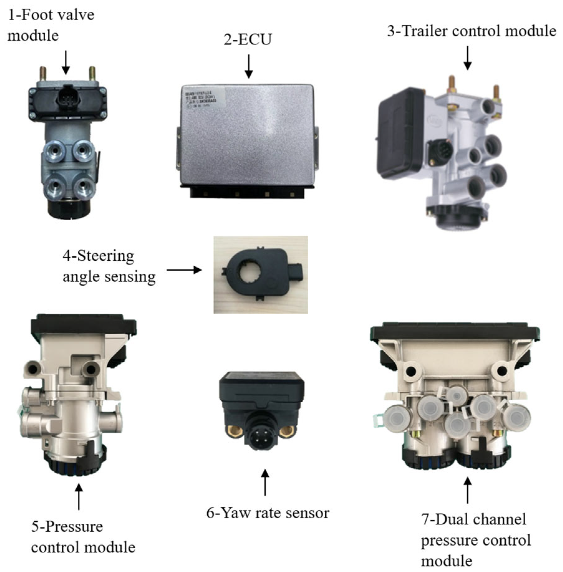
Figure 2 shows a physical diagram of the EBS, in which the foot valve module can generate brake control signals, and its air circuit is partially the same as the conventional foot brake valve and is capable of generating dual circuit signals for both electric and pneumatic control. The pressure control module is responsible for controlling the front and rear axle brake pressure and accepting the target brake pressure value from the ECU, with dual circuit control of electronic and gas pressure preparation and high reliability.

2.2. EBS Rear Axle Control Module Assembly

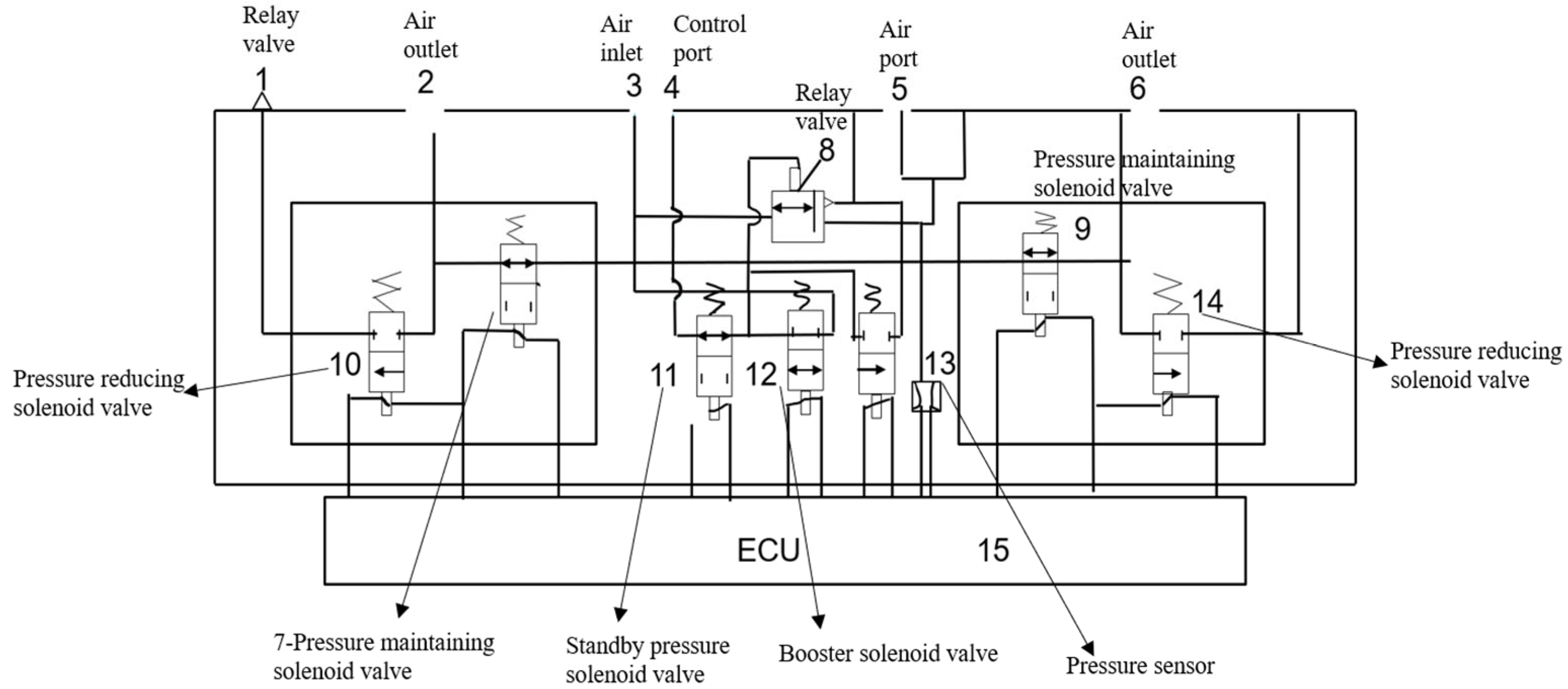
This EBS rear axle module assembly serves as the core component of the EBS, and its performance directly affects the braking effectiveness of the EBS. However, the existing EBS electronically controlled bridge control valve assemblies have a relatively complex layout. Most solenoid valves are placed at the air ports to increase the inner diameter of the air holes, and the independent arrangement of each solenoid valve is not conducive to modularization, resulting in higher costs. For example, the EBS single-channel electronically controlled bridge control valve assembly adopts a dual-control approach that combines pneumatic control and electronic control, allowing the piston to be controlled by the pneumatic circuit. This ensures that the pneumatic control mode can still function normally in the event of an EBS failure, thereby enhancing braking safety. However, its level of integration is insufficient and cannot meet the growing demands for increased integration and lightweight design. To meet the current market demands, this paper proposes a new technical solution. This rear axle control module assembly features an integrated structure, where the air passages between each solenoid valve and the air ports are connected through channels or chambers located within the valve body [14]. Compared with existing technologies, it offers the advantages of being lightweight, compact in structure, fast in response, and cost effective, while also facilitating pipeline layout, installation, and maintenance. Its principle is illustrated in Figure 3.
When the EBS rear axle control module works, the ECU accurately determines the braking demand according to the high-pressure gas introduced from air inlet 3, the brake pedal signal transmitted from control port 4, and the pipeline pressure fed back in real time by pressure sensor 13. Under the normal braking scenario, the ECU commands boost solenoid valve 12 and standby solenoid valve 11 to open and pressure-maintaining solenoid valves 7 and 9 to maintain the initial opening, and the high-pressure gas enters the rear axle braking air circuit from air outlets 2 and 6 after regulation to establish the braking force. When the wheel speed signal shows that the wheel has a locking trend, the ECU triggers the ABS logic and controls the high-frequency on–off of pressure-maintaining solenoid valves 7 and 9, and pressure-reducing solenoid valves 10 and 14 open briefly so as to make the brake pressure pulse adjustment and realize the wheel rolling brake. In the braking release phase, ECU commands each solenoid valve to act in reverse, closes the pressurization and standby valves, opens the pressure-reducing valve, and releases the pressure through the air outlet or exhaust channel to complete the braking process.

2.3. Main Function

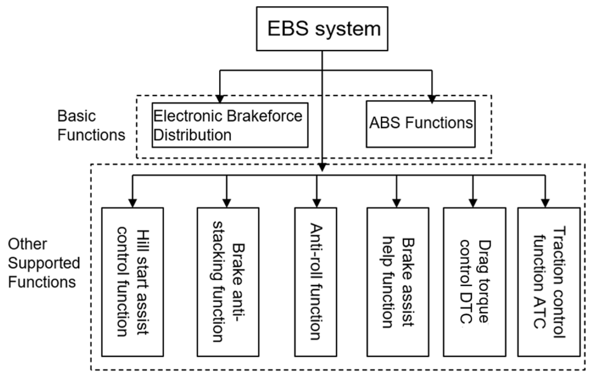
This EBS integrates a large number of other functions on top of the conventional ABS function and electronic brake force distribution, adding safety and comfort for the driver. Its functions are shown in Figure 4.
The drag torque control (DTC) function is an important technology in the automotive power control system. This EBS can automatically compare the drive axle with the reference speed of the vehicle, and if the slip rate of the drive axle is relatively large, it will lead to the loss of stability of the vehicle and lead to traffic accidents [22]. This EBS will individually control the engine to increase the output torque to make the wheels of the drive axle rotate to reduce the slip rate so that the vehicle deceleration can be achieved under the premise of maintaining the stability of the vehicle. The EBS will individually control the engine to increase the output torque so that the wheels of the drive axle will rotate to reduce the slip rate, thus realizing the deceleration of the vehicle while maintaining vehicle stability.
Hill start assist control helps the driver to start smoothly on uphill surfaces by controlling the travel brake pressure release time.
The brake power assist function can help the driver to carry out better assisted braking. According to the driver’s action in promoting the brake pedal speed and the driver’s deceleration requirements, the EBS will automatically increase the braking power output at a maximum of two times the requirements. In the case that the brake assist function, the retarder control, the friction pad wear control, and the coupling force control all stop working, road safety and vehicle stability have the highest priority.

3. Control Strategy and Modeling of EBS

3.1. Working State and Control Mechanism

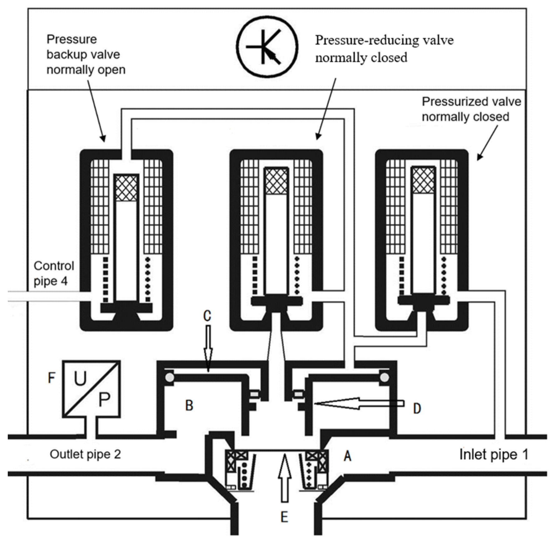
The single-channel control module is the actuating component of the EBS, also known as the output end. Its primary function is to receive the required pressure signal sent by the EBS-ECU via the CAN bus and control the solenoid valve to achieve the desired braking pressure quickly, accurately, and stably. As shown in Figure 5, the schematic diagram illustrates the structure of a single-channel control module. Its main components include a normally open standby pressure valve, a normally closed pressurizing valve, a normally closed pressure-reducing valve, a pressure sensor F, an electronic control unit, and a relay valve, among other parts.
The designed single-channel control module features multi-condition adaptive characteristics, enabling dual-channel braking control with electronic control as the primary method and pneumatic control as a redundant backup. The module automatically switches operating modes based on the type of input signals. The specific working mechanism is analyzed as follows.

3.1.1. Multimodal Operating State Analysis

Electronic control braking mode: When the system detects the pressure demand electrical signal, the module enters the active control state. At this time, the standby pressure valve is stimulated to close (normally open), and the brake chamber pressure is accurately controlled by adjusting the on–off sequence of the pressurization valve/pressure-reducing valve in real time.
Air-controlled braking mode: When there is no electronic control signal, but an air control signal is present, the module switches to a redundant backup state. The standby pressure valve remains open, while the pressure increase/decrease valve group is powered off and closed. The air pressure control signal can directly regulate the pressure entering the brake chamber, forming a mechanically independent braking path separate from the electronic system. However, electronic auxiliary functions are temporarily disabled during this mode, as shown in Figure 5.
Basic standby mode: When both electrical and pneumatic control signals are absent, the module enters a low-power standby state. The pressure sensor performs periodic atmospheric pressure sampling and completes zero-point self-calibration to ensure the system remains ready for rapid response at all times.

3.1.2. Electric Control Dynamic Stress Management Mechanisms

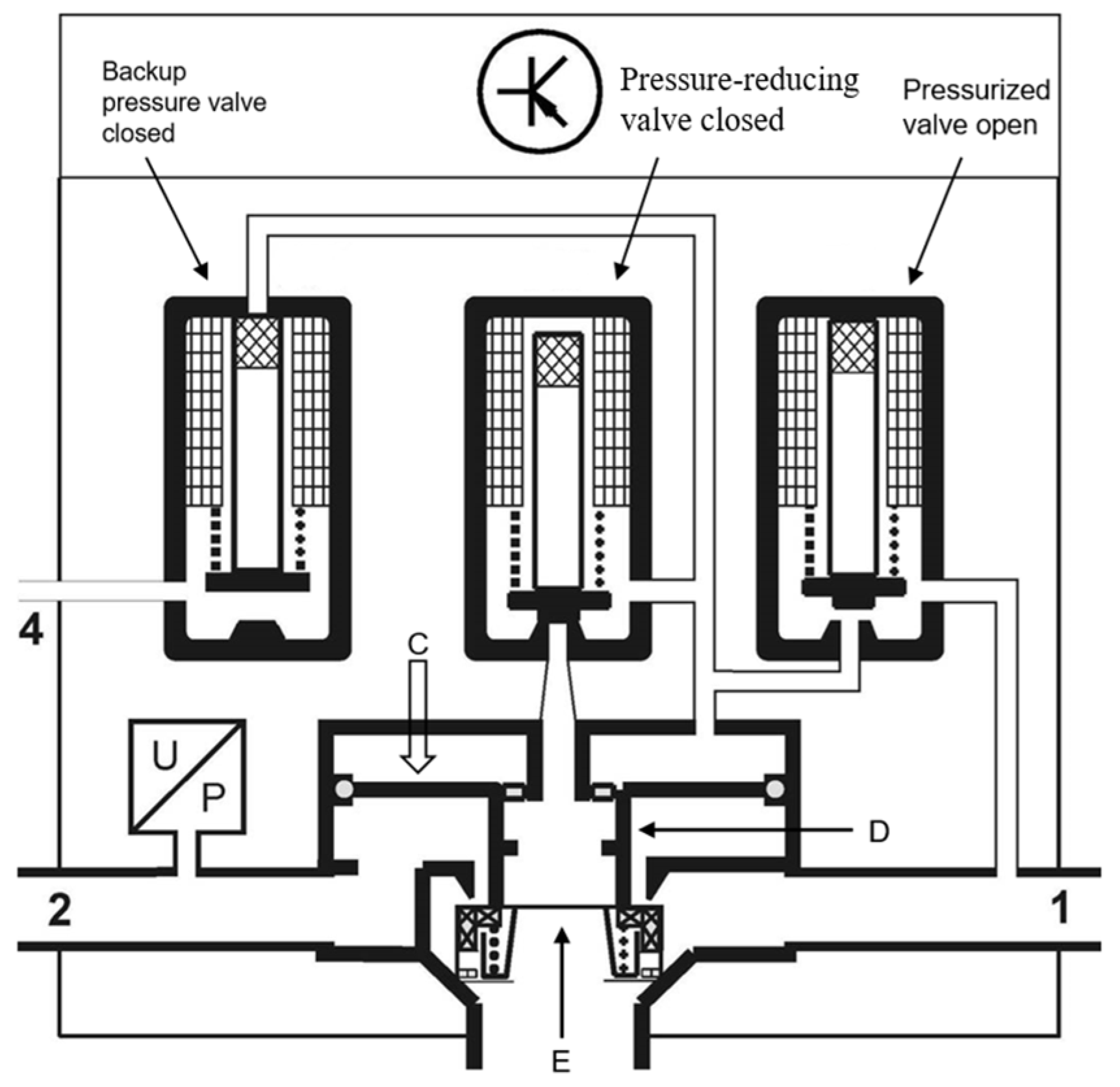
Pressurization process: As shown in Figure 6, during electric-controlled pressurization, the backup pressure valve is energized to close, while the pressurization valve is energized to open. High-pressure gas from intake pipeline 1 passes through the pressurization valve to reach the control chamber C. Under pressure, piston D moves downward, compressing piston E and connecting intake pipeline 1 with exhaust pipeline 2, allowing the pressure to enter the brake chamber.
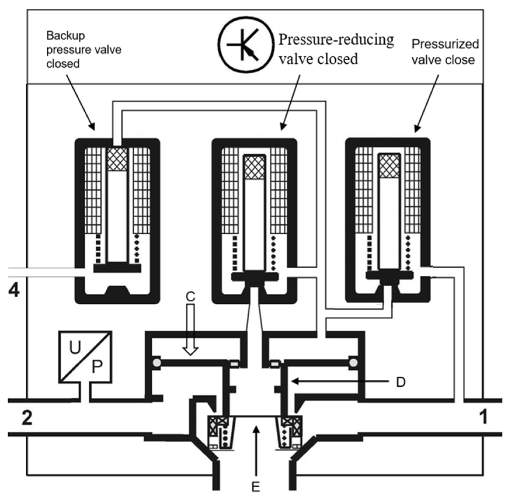
Pressure-holding process: As shown in Figure 7, during electric pressure holding, the backup valve is energized to close, and the pressure-reducing/increasing valve is closed, forming a sealed space in control chamber C. Piston D maintains contact sealing with piston E under balanced pressure on its upper and lower surfaces, effectively stabilizing the pressure in outlet pipe 2.
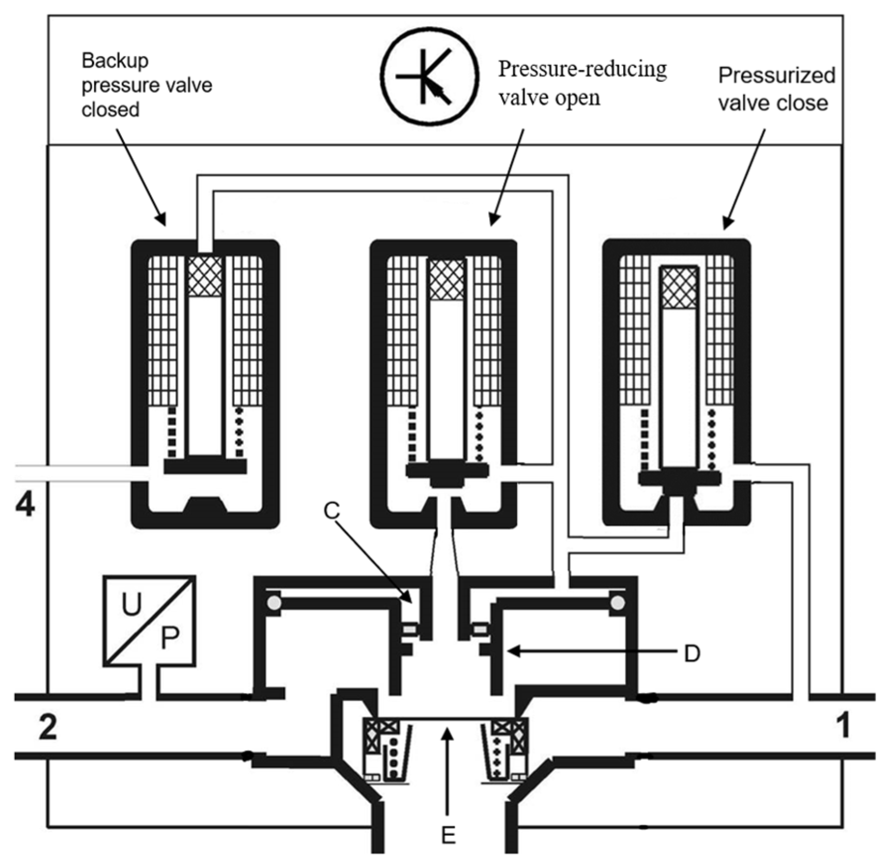
Decompression process: As shown in Figure 8, during electric-controlled decompression, the pressure relief valve opens to release the pressure in control chamber C. The high pressure in exhaust line 2 pushes piston D upward, disengaging it from piston E, allowing the braking gas to escape through the gap between piston E and other components.

3.2. Control System Model

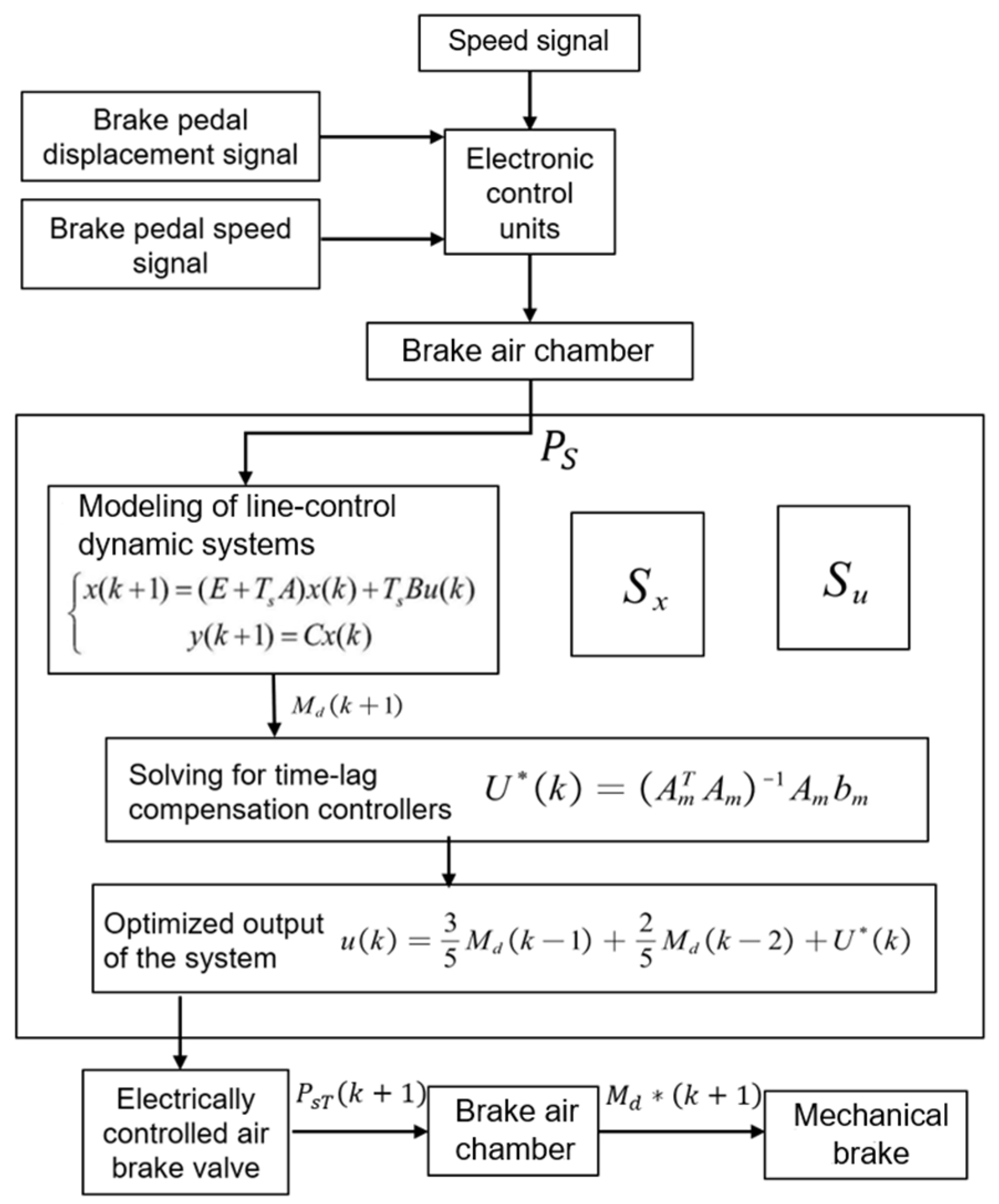
Figure 9 shows the control flowchart. When the driver presses the brake pedal, the pedal sensor sends a signal to the ECU. Based on the electronic brake-by-wire system and by integrating data such as vehicle speed, load, and wheel speed, the ECU calculates the required braking force for each wheel. Subsequently, the ECU sends commands to the electronically controlled pneumatic brake valve to precisely adjust the air pressure delivered to the brake chamber. The brake chamber then converts this air pressure into a mechanical braking torque.
During the braking process, the electronic control unit collects vehicle speed signals, brake pedal displacement signals, and brake pedal velocity signals to calculate the input pressure of the air chamber P s .
The model of the line-control dynamic system is then established as follows:
x k + 1 = E + T s A x k + T s B u k               y K + 1 = C x k
In Equation (1), x = q m   P s   P w , q m is the opening and closing times of the solenoid valve, P s is the input air pressure, P w is the brake pressure on the wheel, y = P s , u = T m , T m is the braking torque on the wheel, T s is the sampling time, K is the linearization coefficient, and k indicates the k-th time.
Based on the brake-by-wire system model and the input pressure P s , the output target torque M d ( k + 1 ) is calculated, and the delay compensation coefficient matrix S x ; S u is solved:
S x = i = 1 τ + 1 C A d i i = 1 τ + N C A d i N *   1 T
S u = 0 0 0 C B 0 i = 1 N τ C A d i 1 B C B i = 1 N + τ C A d i 1 B i = 1 N τ C A d i 1 B
In the formula, τ indicates system delay, A d = E + T s A , and N indicates the length of the forecast pane, solving time delay compensation controller U * k :
U * k = A m T A m 1 A m b m
The optimal control output of this system u k is calculated:
u k = 3 5 M d k 1 + 2 5 M d k 2 + U * k
Based on the control system, the input pressure P s and the target torque M d ( k + 1 )   are optimized by the time delay compensation controller and the system to realize that the electronic control air brake valve controls the brake chamber to output the precise braking pressure P s T k + 1 and the precise mechanical braking target torque M d * ( k + 1 ) to achieve braking; that is, the output mechanical braking torque at k + 1 is
M d * k + 1 = 3 5 M d k 1 + 2 5 M d k 2 + U * k
Thus, the pressure time delay compensation controller for the brake-by-wire system has been successfully configured. The designed control system fully considers the time delay issues caused by factors such as signal transmission and signal processing, effectively mitigating the problem of low control precision in the brake-by-wire system due to time delays, thereby enhancing vehicle safety.

3.3. Simulation Analysis of EBS

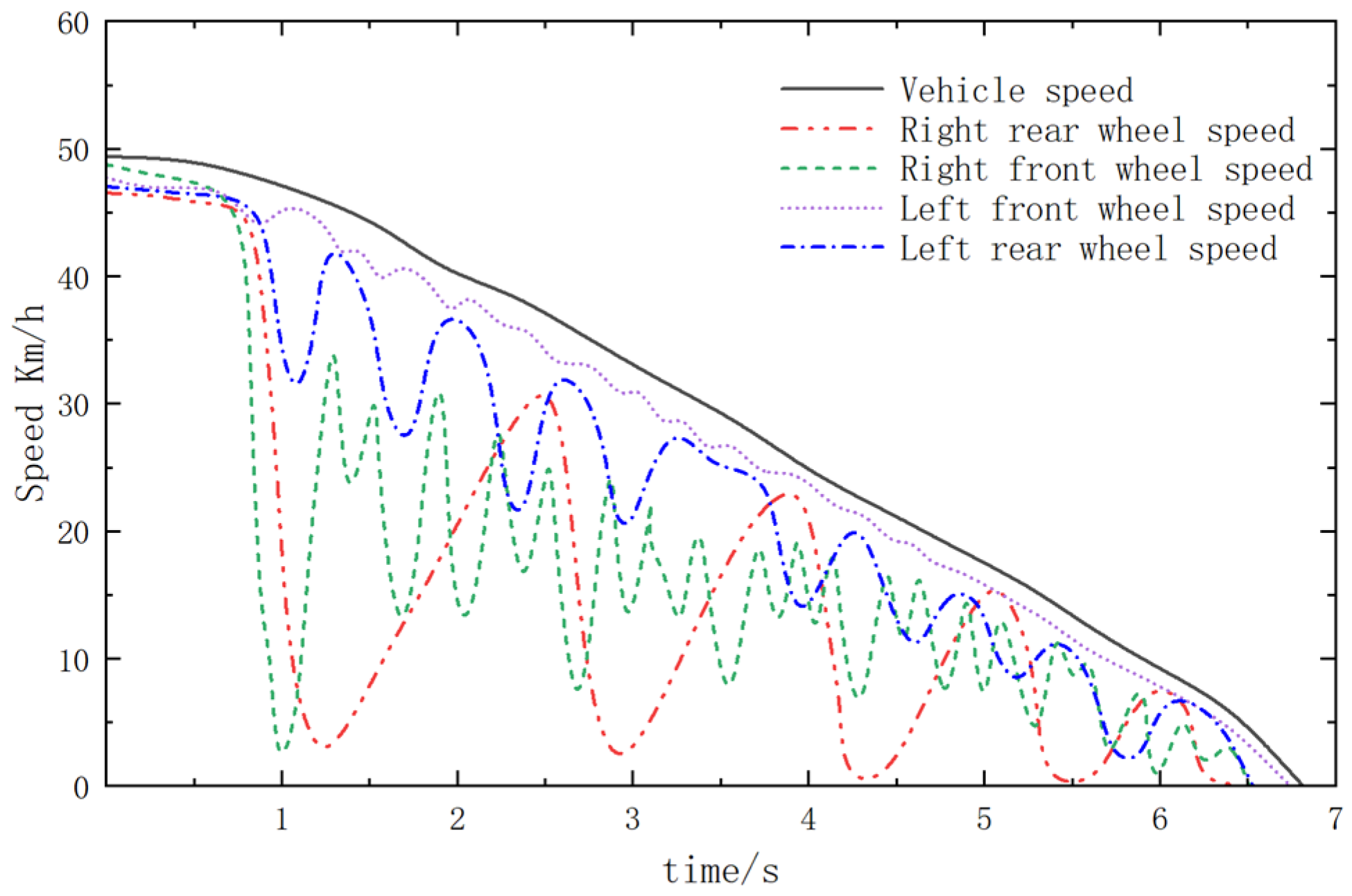
Using the matlab/simulink 2023 module, taking the experimental vehicle as the simulation object, a vehicle braking simulation was carried out based on the designed EBS under a no-load condition on a dry road with an adhesion coefficient of 0.8 on the left and a wet road with an adhesion coefficient of 0.2 on the right, with an initial speed of 50 km/h. The results are shown in Figure 10.
Figure 10 shows that, due to the left side of the vehicle being on a high-adhesion road surface while the right side is on a low-adhesion road surface, the speed variation amplitude (i.e., the slip rate difference) between the left front and left rear wheels exhibits better control performance compared to that between the right front and right rear wheels. Under these road conditions, the vehicle completes braking within 6.8 s. This result indicates that the EBS demonstrates excellent braking performance on split-friction road surfaces.
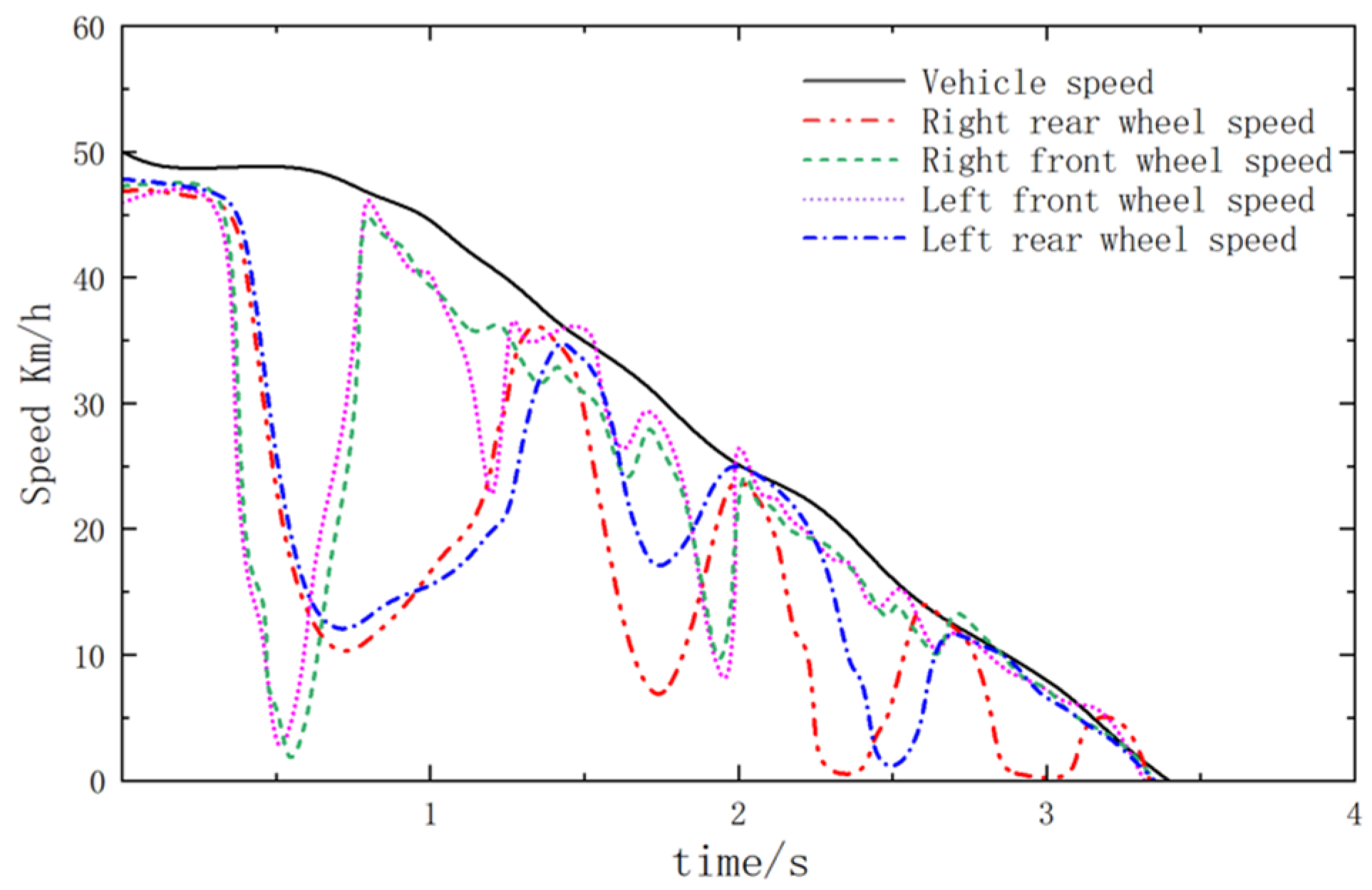
A braking simulation was conducted on a wet and slippery road surface with a low adhesion coefficient connected to a dry road surface with a high adhesion coefficient under no-load conditions at an initial speed of 50 km/h. The results of the vehicle speed variation are shown in Figure 11.
Figure 11 shows that the designed EBS exhibits significant control effectiveness on the slip rate difference between the front and rear wheels on the docking road surface. The time taken for the EBS to bring the vehicle from braking initiation to a complete stop is 3.4 s.
The braking simulation results for the two aforementioned road conditions demonstrate the reliability of this EBS model, providing a reference for subsequent experiments.

4. EBS Experimental Testing Analysis

4.1. Experimental Testing System

The experimental testing system takes a commercial 6 × 4 tractor as the experimental target model, and its main technical parameters are shown in Table 1.
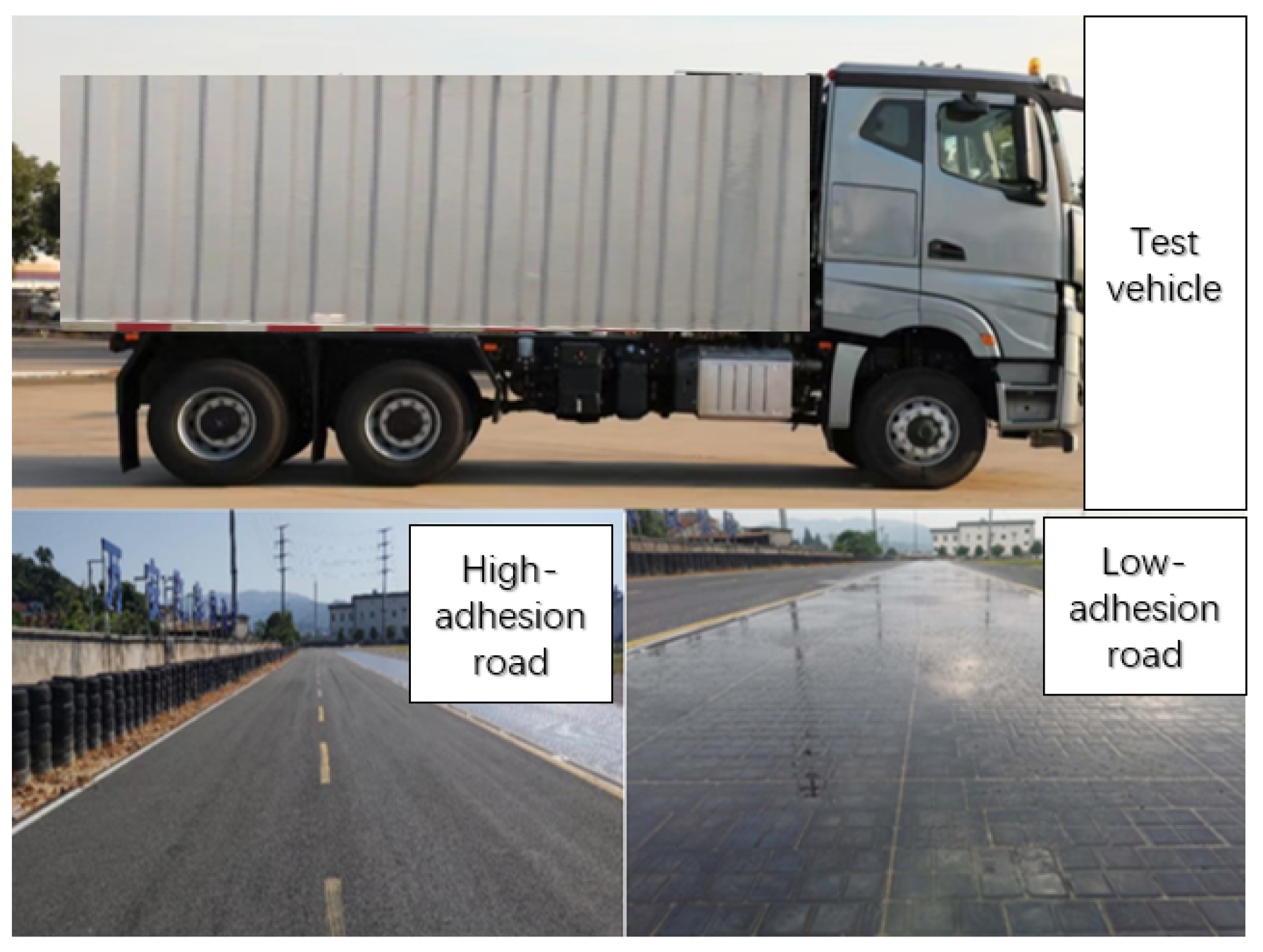
The brake of the experimental vehicle adopts the front drum and rear drum brake and an automatic adjusting arm. The transmission is a manual four-gear transmission. The tire model is Chaoyang 295/80R22.5 (Zhongce Rubber Group Co., Ltd., Hangzhou, China), the number of teeth in the ring gear is 100, and the EBS adopts 4S4M (4 wheel-speed sensors and 4 solenoid valves). The test road surface and test sample vehicle are shown in Figure 12.

4.2. Test Results

4.2.1. Experimental Analysis of Braking on Low-Adhesion Road

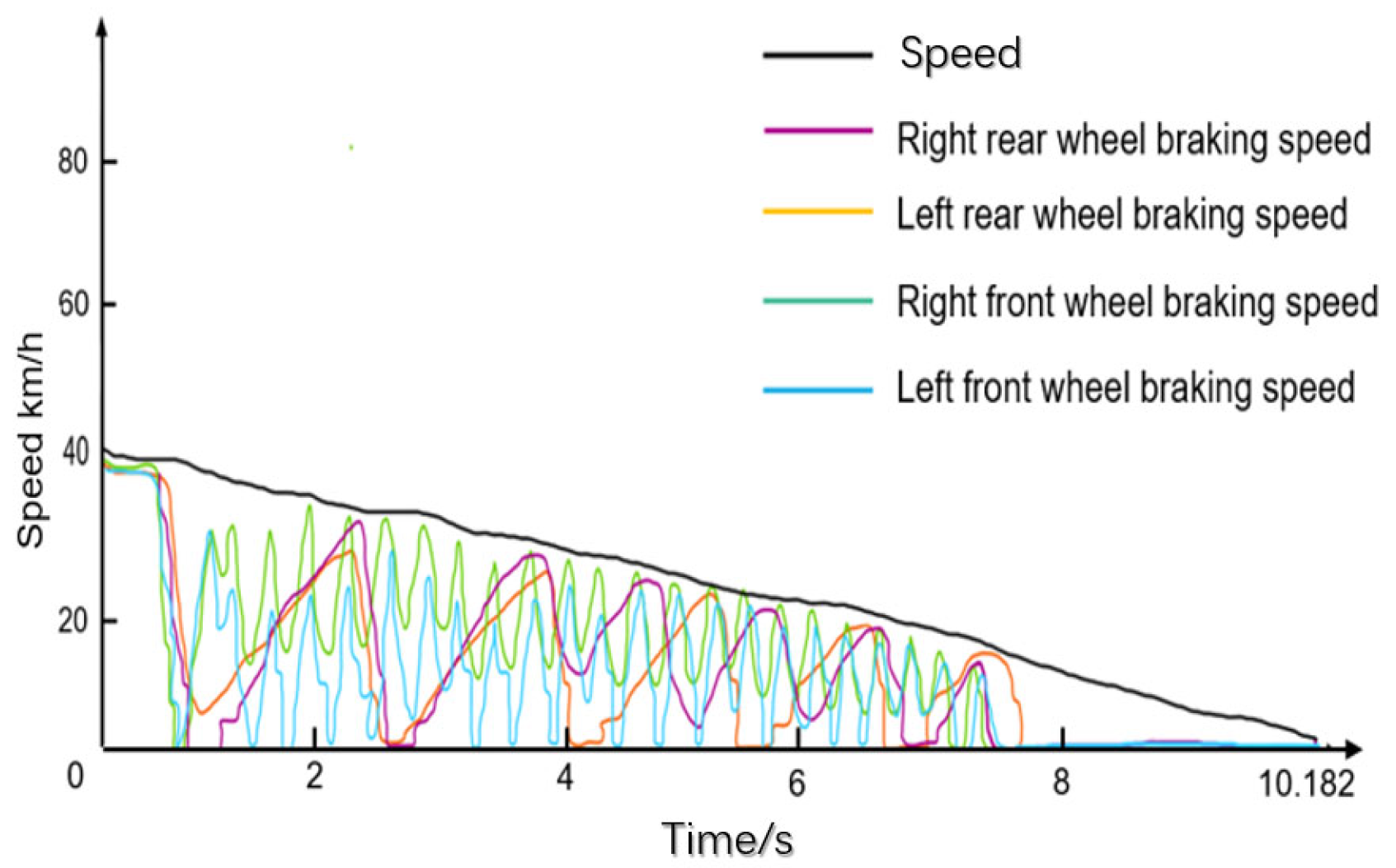
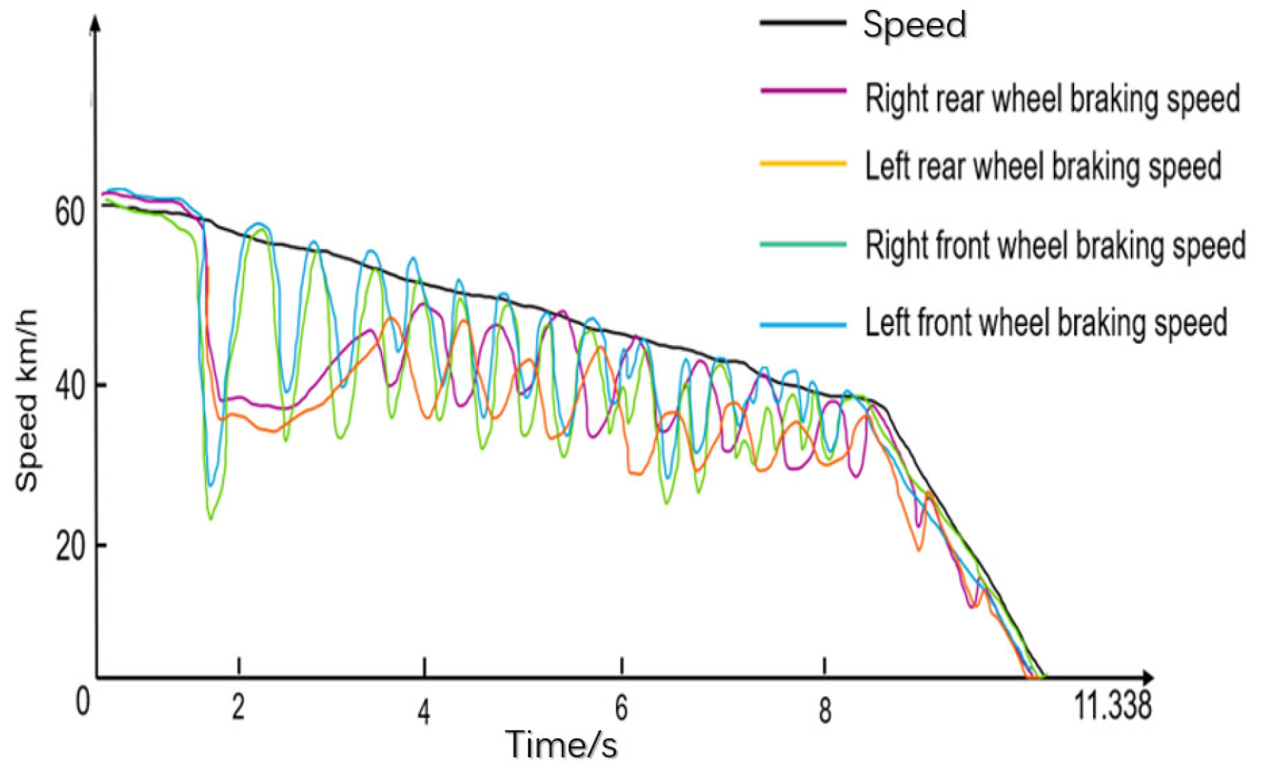
Taking the target vehicle as the experimental object, the braking test is carried out on the watery pavement with the low-adhesion system under no-load conditions with initial speeds of 40 km/h and 60 km/h. The braking results are shown in Figure 13 and Figure 14.
According to Figure 13 and Figure 14, in the straight braking test on low-adhesion-coefficient road surfaces (including waterway surfaces), the braking time under no-load conditions is 10.182 s at an initial speed of 40 km/h and 11.338 s at an initial speed of 60 km/h.
This system adopts a pressure delay compensation control strategy and high-frequency response of the pressure-maintaining/reducing solenoid valve in the rear axle module, significantly reducing the response delay of brake pressure regulation, ensuring that the braking force quickly matches the road adhesion conditions and causing the wheels to only briefly lock up at both initial speeds.
According to the requirements of the GB13594 standard [23] for low-adhesion-road surface braking stability, this system not only meets the specifications but also achieves a breakthrough in traditional braking systems through technological innovation. Traditional systems often lose control of direction due to prolonged lock-up time under low-adhesion conditions at 60 km/h. However, even at higher initial speeds, this system can still ensure the controllability of the braking process through the above technology, fully verifying its safety advantages in low-adhesion high-risk scenarios.
Table 2 shows this braking result compared to the industry’s traditional pneumatic braking result, which is derived from a commercial vehicle test report by East Cork Knoll, a global leader in braking systems. As can be seen from Table 2, this EBS braking result is superior and more stable than conventional ABS systems.

4.2.2. Experimental Analysis of Braking on High-Adhesion Road

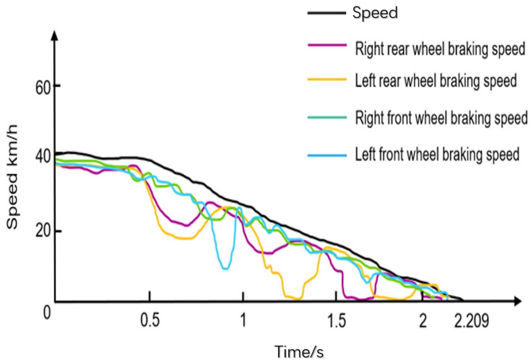
Taking the target vehicle as the experimental object, the braking test is carried out on a straight, dry road with a high coefficient of adhesion under no-load conditions with initial speeds of 40 km/h and 60 km/h. The braking results are shown in Figure 15 and Figure 16.
It can be seen from Figure 15 and Figure 16 that the braking time under this working condition of 40 km/h is 2.209 s, and the test vehicle only locks temporarily and does not drive out of the test channel. According to the standard GB13594, the test results meet the requirements.
The braking time is 3.522 s under the condition of 60 km/h and no load with gear. According to the standard GB12676 [24], the braking distance requirements are s 0.15 v + v 2 / 130   =   3 6.62 m, where v = 59.94   k m / h , the Mean Fully Developed Deceleration M F D D   5   m / s 2 , the experimental braking distance is 22.44 m, and the vehicle does not drive out of the experimental channel, which meets the requirements.

4.2.3. Experimental Analysis of Split and Docking Road Braking

Taking the target vehicle as the experimental object, the no-load neutral braking test with an initial speed of 50 km/h was carried out on a split road with a high coefficient of adhesion on the left and a low coefficient of adhesion on the right. The braking results are shown in Figure 17.
It can be seen from Figure 17 that the braking time of the test is 6.68 s. In the test, the vehicle only locked temporarily. The steering wheel rotation correction within the first 2 s did not exceed 120°, the total angle did not exceed 240°, and the test vehicle did not drive out of the test channel, which met the requirements of the GB13594 standard, and the braking performance was good.
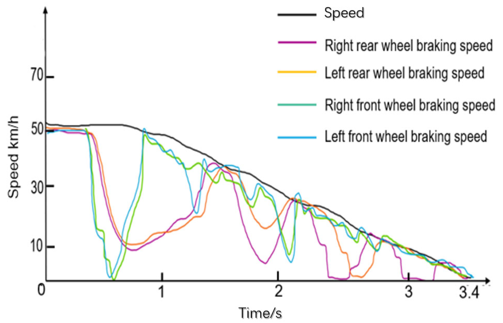
Taking the target vehicle as the experimental object, the no-load neutral braking test with an initial speed of 50 km/h was carried out from the road with a low coefficient of adhesion to the road with a high coefficient of adhesion. The braking results are shown in Figure 18.
It can be seen from Figure 18 that the braking time of the test is 3.4 s. In the test, the vehicle only locked temporarily. During docking, the deceleration of the vehicle increased significantly. The test vehicle did not drive out of the test channel, which met the requirements of the GB13594 standard and had good braking performance.
The experimental results under the above two conditions are consistent with the braking simulation curves under the same road conditions, which verifies the accuracy of the EBS model.
As can be seen from Table 3, the EBS demonstrates excellent path stability and dynamic response under both extreme conditions. On the folio road, despite the large difference between the left and right wheel adhesion coefficients, the system controls the steering wheel correction within the safety threshold (total turning angle <240°) through real-time wheel speed difference monitoring and dynamic allocation of braking force, avoiding the risk of directional loss of control that is common with traditional pneumatic braking; on the buttress road, the braking time is shortened by 48.5% compared with that of the folio condition, which is attributed to the system’s explosive torque response at the instant of recognizing the high-adhesion road surface. This is attributed to the explosive torque response of the system when recognizing a high road surface (solenoid valve response <50 ms), which enables the deceleration rate to jump from 0.3 g to 0.8 g, fully releasing the potential of road surface adhesion.
Compared to the industry benchmark Wilburco EBS (which requires 8° steering wheel correction to inhibit yawing on the opposite side of the road), this system reduces the amount of correction to <3° (see curve in Figure 14), and at the same time shortens the braking distance by 22% compared to an ABS system in the same working conditions (CACR 2024 report).

4.2.4. Comparison of Experimental Results

As shown in Table 4, traditional pneumatic braking has a slow response speed, has low pressure regulation accuracy, and is prone to wheel locking on low-adhesion road surfaces, resulting in poor braking performance and insufficient stability. On the opposite road surface, the difference in the slip ratio is large, and the vehicle is prone to deviation [25]. The braking efficiency fluctuates greatly, and the deceleration is unstable when switching to the road surface. This EBS has reasonable braking time and exhibits excellent braking response performance and safety on both low-adhesion and high-adhesion road surfaces, as well as on opposite and docking road surfaces.

5. Conclusions

In this paper, a new integrated high-response-speed EBS is studied. The delay compensation control method of brake by wire improved the problem of low control accuracy caused by time delay in the linear control system so as to improve vehicle safety. Taking a commercial 6 × 4 tractor as the research object, a braking experiment was carried out on different roads, such as low adhesion, high adhesion, and split butt joint. The EBS has good braking response performance, short braking time, and excellent braking safety performance under various typical working conditions, which meets the requirements of relevant standards, and integrates a variety of functions, bringing higher safety and comfort to the driver. It highly meets the market demand, and has broad application prospects, which is expected to promote the upgrading and development of commercial vehicle braking technology.
However, there are certain limitations to the current research, as it only uses specific models of 6 × 4 commercial tractors as test carriers and does not cover other types of commercial vehicles. The experiments are mainly based on no-load conditions and lack long-term testing data for core components in extreme environments. In the future, it is necessary to expand the adaptability of vehicle models to working conditions, strengthen environmental durability design, optimize functional collaborative control logic, and promote intelligent integration. We also suggest promoting multi-vehicle validation and standardization to enhance the system’s universality, reliability, and application value.

Author Contributions

Conceptualization, F.C. and G.C.; Methodology, Z.F., B.Q., Q.H. and G.L.; Software, X.S. (Xiaoyi Song) and Q.H.; Formal analysis, G.C. and Z.L.; Investigation, G.C. and G.L.; Resources, B.Q. and Q.H.; Data curation, X.S. (Xiaoyi Song); Writing—original draft, G.L.; Writing—review & editing, F.C., Z.F. and X.S. (Xiaoqing Sun); Visualization, Z.L. and G.L.; Supervision, X.S. (Xiaoqing Sun); Project administration, F.C.; Funding acquisition, X.S. (Xiaoyi Song). All authors have read and agreed to the published version of the manuscript.

Funding

This research was supported by the Research and application of key components for new energy vehicles—Research and application of wire-controlled steering system for new energy vehicles (2022C01241).

Data Availability Statement

The data presented in this study are available on request from the corresponding author. The data are not publicly available due to privacy or ethical restrictions of Zhejiang VIE Science & Technology Co., Ltd.

Conflicts of Interest

Authors Feng Chen, Zhiquan Fu, Baoxiang Qiu, Xiaoyi Song, Gangqiang Chen, Zhanming Li and Qijiang He are employed by the company Zhejiang VIE Science & Technology Co., Ltd. The remaining authors declare that the research was conducted in the absence of any commercial or financial relationships that could be construed as a potential conflict of interest.

References

  1. Wang, L.P.; Shang, Y.X. Introduction of EBS electronic braking system. Automob. Technol. 2017, 12801, 139–141. [Google Scholar]
  2. Zhao, Y.; Wang, W.Y. Application of Electronic Brake System (EBS) for Heavy Truck. Auto Electr. Parts 2022, 6, 86–91. [Google Scholar]
  3. Li, J.; Hu, Y.W.; Shi, Q.J.; Zhu, W.W. Research on Simulation Control of Proportional Relay Valve in Electric Bus. Mach. Des. Manuf. 2017, 9, 1–4. [Google Scholar]
  4. Zhang, L.J.; Yan, Y.; Zhu, Q.W.; Zhao, G.; Feng, D.; Wu, J. A Pneumatic Control Method for Commercial Vehicle Electronic Brake System Based on EPV Module. Actuators 2022, 11, 316. [Google Scholar] [CrossRef]
  5. Zhang, Z.S.; Wang, L.F.; Zhang, J.Z.; Ma, R. Study on Requirements for Load Emulation of the Vehicle with an Electric Braking System. IEEE Trans. Veh. Technol. 2017, 66, 9638–9653. [Google Scholar] [CrossRef]
  6. Mara, T.; Roberto, S.; Sergio, M.S. Combining Slip and Deceleration Control for Brake-by-wire Control Systems: A Sliding-mode Approach. Eur. J. Control 2007, 13, 593–611. [Google Scholar]
  7. Wang, J.C. Hierarchical braking accurate control of electrohydraulic composite braking system for electric vehicles. ISA Trans. 2025, 158, 594–608. [Google Scholar] [CrossRef]
  8. Zheng, H.Y.; Liu, Z.Y.; Xu, K.W. Integrated Braking Algorithm Based on Brake Temperature and Wear Loss Control. J. South China Univ. Technol. 2013, 132–136, 142. [Google Scholar]
  9. Zhong, C.F.; Wang, Y.; Zhao, W.Q.; Feng, D.; Wu, J. Development of simulation platform and hysteresis control strategy of pneumatic electronic braking system for commercial vehicles. J. Jilin Univ. (Eng. Technol. Ed.) 2016, 46, 711–717. [Google Scholar]
  10. Xia, W.Y.; Wu, H.P. Application of electronic brake system (EBS) on Trailer. Auto Expo 2021, 16, 37–38. [Google Scholar]
  11. Li, W.J.; Wang, X.H.; Wang, F.; Pu, J.J.; Yan, J.H. Application of electronic braking system in new energy commercial vehicle. Automob. Technol. 2020, 24, 4–5. (In Chinese) [Google Scholar]
  12. Yu, B.; Zhao, R.; Yang, F.; Li, G.Y. Function and system design of pneumatic EBS for dangerous goods semitrailer. Highw. Automot. Appl. 2021, 2, 1–6. [Google Scholar]
  13. Jamal, E.; Hamid, O.; Abdallah, S. Adaptive Neuro Fuzzy Inference System Based controller for Electric Vehicle’s hybrid ABS braking. IFAC-PapersOnLine 2022, 55, 371–376. [Google Scholar]
  14. Yang, M.; Hu, Z.X. Application of EBS in Trailer. Commer. Veh. 2019, 12, 101–103. [Google Scholar]
  15. Song, Y.L.; Xie, K.C. Application of EBS in heavy truck. Heavy Truck. 2015, 5, 29–31. [Google Scholar]
  16. Salaani, M.K.; Rao, S.; Every, J.L.; Mikesell, D.R.; Barickman, F.; Elsasser, D.; Martin, J. Hardware-in-the-Loop Pneumatic Braking System for Heavy Truck Testing of Advanced Electronic Safety Interventions. SAE Int. J. Passeng. Cars Mech. Syst. 2016, 9, 912–923. [Google Scholar] [CrossRef]
  17. Morrison, G.; Cebon, D. Combined emergency braking and turning of articulated heavy vehicles. Veh. Syst. Dyn. Int. J. Veh. Mech. Mobil. 2017, 55, 725–749. [Google Scholar] [CrossRef]
  18. Halilović, A.; Zimmerschitt-Halbig, P. ISO 26262 for Electronic Brake Systems Software. Auto Tech Rev. 2014, 3, 42–47. [Google Scholar] [CrossRef]
  19. Hakan, K.; Ersin, T. Experimental study on braking and stability performance during low speed braking with ABS under critical road conditions. Eng. Sci. Technol. 2021, 24, 1224–1238. [Google Scholar]
  20. van der Merwe, N.A.; Els, P.S.; Žuraulis, V. ABS braking on rough terrain. J. Terramech. 2018, 80, 49–57. [Google Scholar] [CrossRef]
  21. Bao, H.W.; Wang, K.Y.; Wei, X.X.; Cheng, Y.; Zhao, M.; Li, G. Highly Redundant Safety Scheme and Its Experimental Validation for the Electronic-Controlled Pneumatic Braking System of Commercial Vehicle for Autonomous Driving. IEEE Access 2024, 12, 138201–138210. [Google Scholar] [CrossRef]
  22. Bao, H.W.; Li, G.Y.; Du, S.Y.; Liu, Y.; Liu, Y. Research on the Influence of Commercial Vehicle Electronic Control Pneumatic Braking Pressure Change Rate on Braking Ride Comfort. Integr. Ferroelectr. 2021, 271, 265–278. [Google Scholar] [CrossRef]
  23. GB/T 13594-2003; Antilock Braking Performance and Test Procedure for Motor Vehicles and Their Trailers. The Standardization Administration of the People’s Republic of China: Beijing, China, 2023.
  24. GB/T 12676-2014; Technical Requirements and Testing Methods for Commercial Vehicle and Trailer Braking Systems. The Standardization Administration of the People’s Republic of China: Beijing, China, 2014.
  25. Soliman, A.M.; Kaldas, M.; Soliman, A.M.; Huzayyin, A.S. Vehicle Braking Performance Improvement via Electronic Brake Booster. SAE Int. J. Veh. Dyn. Stab. NVH 2024, 8, 63–79. [Google Scholar] [CrossRef]
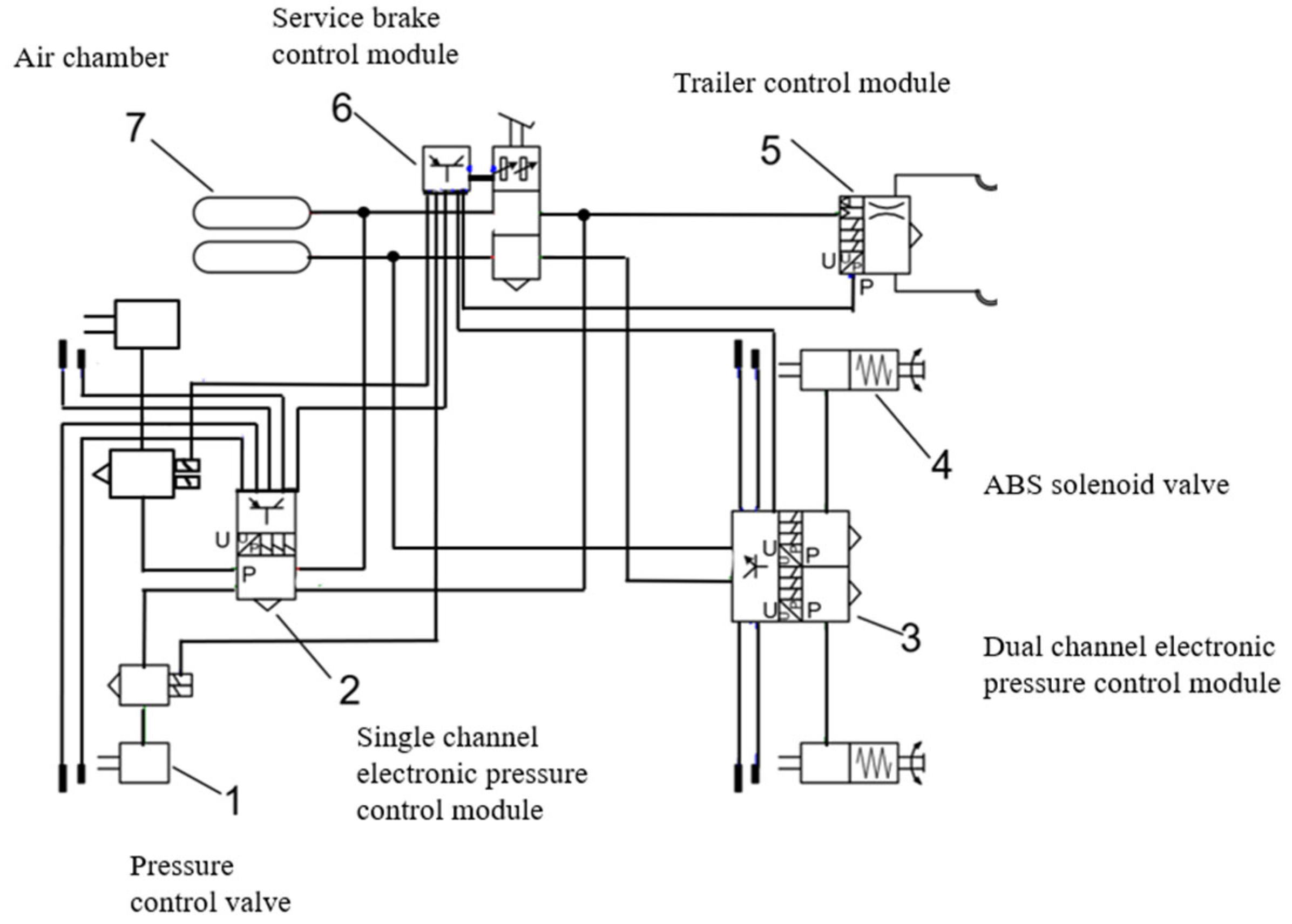
Figure 1. Schematic diagram of EBS.
Wevj 16 00446 g001
Figure 2. EBS physical image.
Wevj 16 00446 g002
Figure 3. Schematic diagram of the EBS rear axle module.
Wevj 16 00446 g003
Figure 4. EBS function diagram.
Wevj 16 00446 g004
Figure 5. Single-channel control module.
Wevj 16 00446 g005
Figure 6. EBS pressurization.
Wevj 16 00446 g006
Figure 7. EBS pressure holding.
Wevj 16 00446 g007
Figure 8. EBS pressure reduction.
Wevj 16 00446 g008
Figure 9. EBS control flow chart.
Wevj 16 00446 g009
Figure 10. Simulation diagram of split road braking.
Wevj 16 00446 g010
Figure 11. Simulation diagram of docking road braking.
Wevj 16 00446 g011
Figure 12. Test vehicle and road.
Wevj 16 00446 g012
Figure 13. No-load 40 km/h initial speed braking diagram of low auxiliary road.
Wevj 16 00446 g013
Figure 14. No-load 60 km/h initial speed braking diagram of low auxiliary road.
Wevj 16 00446 g014
Figure 15. No-load neutral 40 km/h initial speed braking diagram on high-adhesion road.
Wevj 16 00446 g015
Figure 16. No-load neutral 60 km/h initial speed braking diagram on high-adhesion road.
Wevj 16 00446 g016
Figure 17. No load 50 km/h initial speed braking diagram of high-adhesion road on the left and low-adhesion road on the right.
Wevj 16 00446 g017
Figure 18. Braking diagram of no-load butt joint speed 50 km/h on low-adhesion to high-adhesion roads.
Wevj 16 00446 g018
Table 1. Technical parameters of the whole vehicle.
Size parameter(mm)WheelbaseNo-load centroid heightFull-load centroid height
3300 + 13509001325
No load and axle load (kg)No loadFront axle loadRear axle load
796036004360
Full load and axle load (kg)Full loadFront axle loadRear axle load
25,25066504980
Table 2. Comparison of low-attachment no-load braking.
Test ScenarioResults of this EBSConventional Pneumatic BrakesEnhancement Effect
40 km/h no-load braking time10.182 s12.1–13.5 s15–20% reduction
60 km/h no-load braking time11.338 s14.2–15.8 s20–25% reduction
Directional stabilityNo lane departureCommon offsets > 1 m30%+ improvement in control accuracy
Table 3. Comparison of split road and docking road.
Test ConditionsBraking TimeSteering Wheel CorrectionKey Phenomena
Split road6.68 s<120° in the initial 2 s
Total turning angle <240°
Maintaining trajectory stability after a short hold
Docking road3.4 sNo significant amendments triggeredSudden increase in deceleration when connecting to highways
Table 4. Comparison of traditional pneumatic braking with EBS braking in this article.
Braking System TypeWorking ConditionInitial SpeedBraking Time
Traditional pneumatic braking systemLow-adhesion road40 km/h12.1–13.5 s
Traditional pneumatic braking systemHigh-adhesion road40 km/h4–6 s
New integrated EBS Low-adhesion road40 km/h10.182 s
New integrated EBS High-adhesion road40 km/h2.209 s
Traditional pneumatic braking systemSplit road50 km/h8–12 s
New integrated EBS Split road50 km/h6.68 s
Traditional pneumatic braking systemDocking road50 km/h5–7 s
New integrated EBS Docking road50 km/h3.4 s
Disclaimer/Publisher’s Note: The statements, opinions and data contained in all publications are solely those of the individual author(s) and contributor(s) and not of MDPI and/or the editor(s). MDPI and/or the editor(s) disclaim responsibility for any injury to people or property resulting from any ideas, methods, instructions or products referred to in the content.