Article

Techno-Economic Analysis of Hydrogen Hybrid Vehicles

1
Hubei Key Laboratory of Power System Design and Test for Electrical Vehicle, Hubei University of Arts and Science, Xiangyang 441053, China
2
Hubei Longzhong Laboratory, Hubei University of Arts and Science, Xiangyang 441000, China
3
School of Automotive Studies, Tongji University, Shanghai 201804, China
4
Foshan Xianhu Laboratory of the Advanced Energy Science and Technology Guangdong Laboratory, Xianhu Hydrogen Valley, Foshan 528200, China
5
Library, Hubei University of Arts and Science, Xiangyang 441053, China
*
Author to whom correspondence should be addressed.
World Electr. Veh. J. 2025, 16(8), 418; https://doi.org/10.3390/wevj16080418
Submission received: 6 June 2025 / Revised: 9 July 2025 / Accepted: 21 July 2025 / Published: 24 July 2025

Abstract

Driven by carbon neutrality and peak carbon policies, hydrogen energy, due to its zero-emission and renewable properties, is increasingly being used in hydrogen fuel cell vehicles (H-FCVs). However, the high cost and limited durability of H-FCVs hinder large-scale deployment. Hydrogen internal combustion engine hybrid electric vehicles (H-HEVs) are emerging as a viable alternative. Research on the techno-economics of H-HEVs remains limited, particularly in systematic comparisons with H-FCVs. This paper provides a comprehensive comparison of H-FCVs and H-HEVs in terms of total cost of ownership (TCO) and hydrogen consumption while proposing a multi-objective powertrain parameter optimization model. First, a quantitative model evaluates TCO from vehicle purchase to disposal. Second, a global dynamic programming method optimizes hydrogen consumption by incorporating cumulative energy costs into the TCO model. Finally, a genetic algorithm co-optimizes key design parameters to minimize TCO. Results show that with a battery capacity of 20.5 Ah and an H-FC peak power of 55 kW, H-FCV can achieve optimal fuel economy and hydrogen consumption. However, even with advanced technology, their TCO remains higher than that of H-HEVs. H-FCVs can only become cost-competitive if the unit power price of the fuel cell system is less than 4.6 times that of the hydrogen engine system, assuming negligible fuel cell degradation. In the short term, H-HEVs should be prioritized. Their adoption can also support the long-term development of H-FCVs through a complementary relationship.

1. Introduction

Global energy and transportation systems face significant challenges due to carbon emissions and increasing environmental pressures [1,2]. As a renewable energy carrier, hydrogen has emerged as a promising alternative to conventional fossil fuels. In transportation applications, hydrogen power systems demonstrate high efficiency, ranging from 40% to 60%, while producing zero CO2 emissions and substantially reducing lifecycle carbon emissions [3,4,5,6,7].
Hydrogen hybrid vehicles utilize two primary power sources: either a hydrogen fuel cell (H-FC) or a hydrogen internal combustion engine (H-ICE) used with a battery energy storage system. Among these, hydrogen fuel cell hybrid vehicles (H-FCVs) offer advantages such as high efficiency and zero emissions [8]. However, H-FCVs face challenges, including high costs and limited durability [9]. Conversely, H-ICE systems, adapted from traditional internal combustion engines, provide a more cost-effective solution with lower fuel purity requirements while maintaining zero CO2 emissions [10]. According to the ISO 14687, H-FCs require hydrogen with a purity of 99.97%, allowing non-hydrogen gases at concentrations below 0.03%, whereas H-ICE systems can operate with hydrogen purity as low as 98%, tolerating up to 2% non-hydrogen gases [11]. Therefore, it is crucial to assess and compare the operating costs of H-FC and H-ICE systems, considering their respective differences.
Kuyumcu et al. compared the well-to-wheel lifecycle costs of gasoline, hydrogen, and diesel internal combustion engines, as well as hydrogen internal combustion engine hybrid electric vehicles (H-HEVs) and battery electric vehicles. Their findings suggest that H-ICE vehicles and H-HEVs are expected to offer significant cost advantages over conventional internal combustion engine vehicles in the future [12]. Wallner et al. conducted fuel economy tests on the BMW Hydrogen 7 mono-fuel demonstration vehicle, which adopts a H-ICE. Their results showed that its hydrogen consumption reached 3.7 kg/100 km under the Federal Test Procedure 75 (FTP-75) cycle and 2.1 kg/100 km under highway driving conditions [13]. Kyjovský et al. explored the integration of a 1.5 L turbocharged H-ICE in a light hybrid vehicle, demonstrating a peak thermal efficiency of up to 42%, with efficiency exceeding 38% under most operating conditions. Simulations based on the Worldwide Harmonized Light Vehicles Test Cycle (WLTC) estimated hydrogen consumption at 1.14 kg/100 km [14].
Although existing research has preliminarily demonstrated the cost advantages and technical potential of H-ICE, comprehensive analyses of the total cost of ownership (TCO) for H-HEVs remain limited. Meanwhile, the widespread adoption of H-FCVs is constrained by their high system costs and durability limitations. Jeong et al. found that H-FC cost, hydrogen price, and system size significantly impact the TCO of H-FCVs, while battery power capacity is closely correlated with fuel economy [15]. Studies [16,17] suggest that introducing subsidies and fuel credits, scaling up production, and employing effective energy management strategies (EMSs) can mitigate TCO, reduce hydrogen consumption, and minimize energy degradation. Mohammed et al. further reviewed EMSs and optimal power source selection for H-FC/battery/supercapacitor hybrid electric vehicles, highlighting that integrated optimization approaches enable optimal system sizing and energy management, extending component lifespan and reducing energy consumption [18].
However, many studies fail to quantify the economic impact of H-FC system degradation, instead focusing on reducing degradation by optimizing system sizing. Xu et al. developed a dual-loop optimization framework based on the dynamic programming (DP) algorithm and Pareto optimality to optimize component sizing, ultimately minimizing H-FC power output degradation [19]. Madadi et al. used the arithmetic average of steady-state power demand under varying driving conditions to determine the maximum H-FC stack power, effectively improving lifespan while lowering both initial and operating costs [20]. De Almeida et al. analyzed the impact of hybridization on fuel economy, performance, and costs, demonstrating that increasing the hybrid ratio significantly reduces H-FC size and vehicle costs. However, the effects of H-FC degradation on vehicle performance, hydrogen consumption, and economy were not considered [21].
Other studies have focused on optimizing fuel economy and system durability through EMSs. da Silva et al. explored the relationship between H-FCV performance and multi-objective optimization, employing a fuzzy controller for power distribution and an interactive adaptive-weight genetic algorithm to optimize H-FC degradation and hydrogen consumption [22]. Song et al. proposed an EMS based on a deep deterministic policy gradient reinforcement learning model, incorporating degradation costs into the operational strategy and enabling real-time optimization of power distribution [23]. Wang et al. introduced a loss evaluation function for system operation losses, employing the extended Kalman filter algorithm for parameter identification and sequential quadratic programming to minimize operational losses [24]. Zhou et al. proposed an online real-time cost optimization strategy, integrating hydrogen consumption and H-FC degradation into the cost function, demonstrating its effectiveness [25]. Wu et al. developed a multi-objective reinforcement learning EMS that considers equivalent hydrogen consumption, H-FC degradation, and battery lifespan decay, aiming to reduce TCO [26]. Hua et al. proposed a multi-objective optimization strategy, accounting for H-FC lifespan degradation, hydrogen economy, and battery state of charge (SOC) fluctuations, solving it via sequential quadratic programming [27].
Most existing research on these vehicles primarily focuses on the TCO analysis of H-FCVs, while systematic investigations comparing the techno-economic aspects of H-HEVs remain limited [28]. In particular, there is a notable lack of comparative studies conducted on a unified vehicle platform, which is essential for ensuring objective and consistent evaluations. Furthermore, previous studies predominantly optimize energy source degradation and energy consumption costs, overlooking the influence of hydrogen energy system component sizing and system degradation on the overall economy and TCO of hydrogen hybrid vehicles. Given the origin of H-ICEs from conventional ICE technology, H-HEVs are generally assumed to exhibit high durability and negligible performance degradation. In contrast, H-FCs are prone to efficiency degradation and lifespan limitations under dynamic operating conditions, making it essential to consider their degradation behavior in realistic assessments. In addition, existing studies overlook the practical effects of hydrogen purity and price variations in real-world applications. Therefore, to address these limitations, this study presents a unified platform-based modeling framework to systematically compare H-FCVs and H-HEVs under consistent conditions. The contributions of this research can be outlined as follows.
(1)
A unified modeling and simulation framework is established to enable fair comparisons between H-FCV and H-HEV systems under identical drive cycles, environmental conditions, and component boundaries.
(2)
A degradation-aware techno-economic optimization strategy is developed, explicitly modeling H-FC efficiency degradation and battery aging effects using empirical lifetime degradation maps. The strategy jointly minimizes TCO and hydrogen consumption using a multi-objective optimization algorithm combining DP and evolutionary heuristics.
(3)
A comprehensive sensitivity analysis on hydrogen purity and price variation to evaluate their real-world impact on TCO and hydrogen consumption.
The remaining sections of the paper are organized as follows: Section 2 describes the powertrain system and optimization methods for the two vehicle types; Section 3 introduces the multi-parameter co-optimization for hydrogen hybrid vehicles; Section 4 presents the analysis and discussion; and Section 5 concludes this study.

2. Powertrain Configurations and Methods

2.1. Powertrain Structure

The hydrogen hybrid system comprises a hydrogen power system and a lithium-ion (Li-ion) battery energy storage system. As illustrated in Figure 1, the system consists of an H-ICE/H-FC, hydrogen storage system, Li-ion battery, DC/AC inverter, DC/DC converter, and integrated starter generator (ISG) motor. In this configuration, the H-ICE and H-FC function as the primary energy sources, supplying power to the system. The H-FC transmits energy to the ISG motor via a unidirectional DC/DC converter, while the H-ICE converts mechanical energy into electrical energy through the ISG motor. Additionally, the DC/AC inverter enables the ISG motor to convert H-ICE energy or regenerative braking energy into electrical energy stored in the battery, improving overall energy efficiency.
The key vehicle parameters are detailed in Table 1.

2.2. Vehicle and Key Components Modeling

The powertrain model comprises a backward vehicle dynamics model, a H-FC durability degradation model, and a battery lifespan degradation model. The required traction force F v at the vehicle wheels is determined as follows:
F v = f m g cos θ + m g s i n θ + C D A v 2 21.15 + δ m a
where f denotes the rolling resistance coefficient, θ the road gradient, C D the aerodynamic drag coefficient, A the frontal area, δ the rotational inertia factor, a the acceleration, v the vehicle speed, and 21.15 is a unit conversion coefficient consistency.
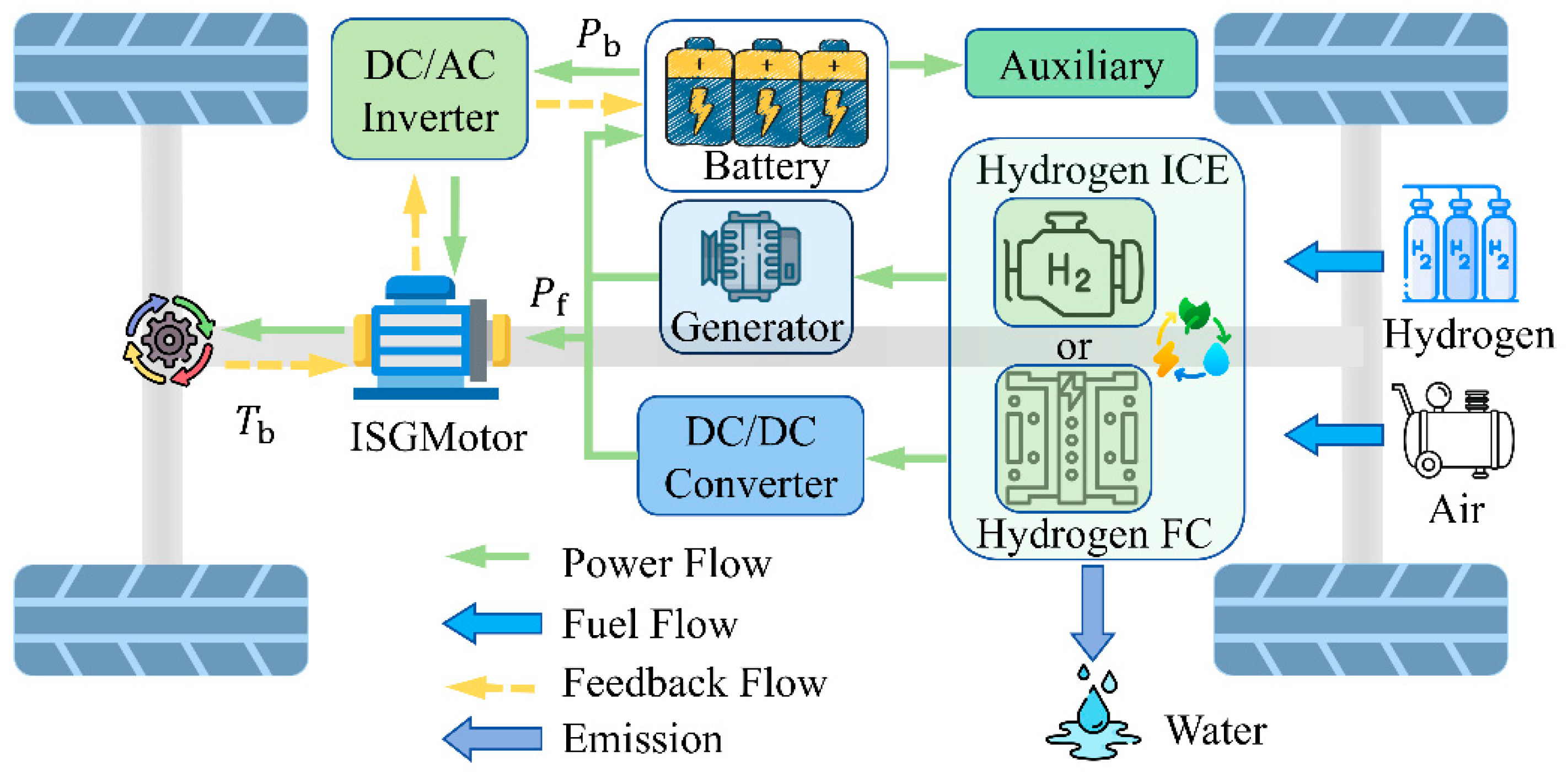
In the vehicle powertrain, the hydrogen energy power system and the battery power system operate collaboratively to supply energy to the electric motor. As expressed in Equation (3), the value of η m is derived from the motor MAP, which characterizes the relationship between efficiency, torque, and speed, as depicted in Figure 2.
Thus, the total power required by the motor, denoted as P r , is expressed as follows:
w r = i r × w v
P r = F v × w r i r × η t × η m , F v 0 F v × w r × η t × η m i r , F v < 0
P r = P b × η D / A + P f × η D / D
Here, w v is the wheel angular velocity, i r the wheel final drive ratio, η t the wheel transmission efficiency, and η m the motor transmission efficiency. The DC/AC inverter efficiency is denoted as η D / A , while η D / D refers to the DC/DC converter efficiency. The power contributions from the hydrogen energy system and the power battery are represented by P f and P b , respectively. Figure 3 illustrates the H-ICE efficiency under varying rotational speeds and brake mean effective pressure (BMEP) conditions, based on experimental data obtained from the test platform [29].
The efficiency curves of the H-FC are derived from data on the Toyota Mirai H-FCV, as provided by Argonne National Laboratory. The studied H-FC delivers a maximum power output of 114 kW and a rated power of 100.7 kW. The specific efficiency characteristics of the hydrogen energy system are presented in Figure 4 [30].
The hydrogen energy power system is simplified for the economy and system durability analysis, employing a physical modeling approach. The hydrogen fuel mass flow rate (kg/s) m H 2 is determined by the following equation:
m H 2 = P f L H V × η f
where η f represents the efficiency of the hydrogen energy system, and LHV denotes the lower heating value of hydrogen (120 MJ/kg).
As part of the energy storage system, the power battery supplies energy while also capturing regenerative braking energy. The equivalent circuit model is adopted to effectively characterize the state of the battery during charge and discharge processes. The SOC is determined by the following equation:
S O C t ) = S O C t 0 I b Q b d t
where S O C t ) represents the current SOC of the battery, I b the battery current, and Q b the battery capacity. The instantaneous battery current I b is determined by the following equation:
I b = V o c V o c 2 4 R b P b 2 R b
where V o c represents the battery open-circuit voltage, R b the battery charge and discharge internal resistance, and P b the battery power. The relationship between battery open-circuit voltage, equivalent internal resistance, and SOC at 25 °C is illustrated in Figure 5.

2.3. Estimation of Operational Costs Considering Powertrain Degradation

The H-FC and Li-ion battery systems experience performance degradation under operating, which contributes to an increase in energy consumption. Their long-term durability can be assessed based on the decline over time [31]. Pei et al. proposed an H-FC degradation model, identifying key degradation mechanisms associated with start/stop cycles, idling, load variations, and high-power loads [32]. Song et al. further validated the model under comparable conditions but at twice the power level, yielding consistent degradation trends [33]. This study incorporates the intrinsic degradation of the H-FC system based on the empirical degradation modeling framework proposed in [34]. The specific parameter definitions are listed in Table 2, and the corresponding performance degradation is expressed as follows:
P l o s s = K p × ( P 1 n 1 + P 2 n 2 + P 3 t 1 + P 4 t 2 + β )
where P l o s s represents the power degradation rate, K p the acceleration coefficient, and β the natural degradation rate. The parameters   P 1 , P 2 , P 3 , and   P 4 quantify the degradation rates due to load variations, start/stop cycles, idling, and high-power operation, respectively. The variables n 1 and n 2 indicate the number of load variations and start/stop cycles, respectively, while t 1 and t 2 denote the idling (low-power) duration and high-power operation time.
Due to its improved thermal efficiency, hydrogen compatibility, and emission performance compared to conventional internal combustion engines, the H-ICE exhibits a comparable lifespan and is typically not subject to a fixed retirement period. Moreover, H-ICE experiences relatively minor performance degradation compared to H-FC, resulting in a limited impact on the TCO. Therefore, the performance degradation of the H-ICE is not considered in this study. In contrast, the degradation of the H-FC system inevitably impacts system efficiency, with degradation rates varying under different current conditions. The voltage drop exhibits a linear relationship with current [35]. Consequently, in physical model-based systems, it is assumed that the current remains constant, leading to a direct correlation between voltage and the required power. The power loss at the rated current serves as the basis for determining the polarization curve.
Furthermore, as described in [36], the H-FC efficiency consists of fuel efficiency, conversion efficiency, and electrical efficiency. It is assumed that the electrical efficiency remains constant and the fuel efficiency is close to 1 and does not change during degradation. The conversion efficiency, however, depends solely on H-FC power output and declines as the power decreases over time due to degradation. Thus, the power and efficiency degradation under any current is characterized as follows:
P f _ d = 1 P i n i t i max P i n i t × l o s s × P i n i t ( i )
η f _ d = 1 P f _ d i max P f _ d × l o s s × P f _ d ( i )
0 < l o s s < 0.1
where P f _ d represents the H-FC degradation power curve (kW), i the sample index, P i n i t the initial H-FC power curve, and l o s s the total H-FC system loss. The parameter η f _ d characterizes the H-FC degradation efficiency curve. Based on these considerations, this study establishes an H-FC degradation model centered on power decline. The degradation model for H-FC is based on power decline. In this study, the end-of-life of the H-FC is defined as the point when the system power output decreases to 90% of its initial value, corresponding to a 10% degradation in rated performance [37]. The degradation rate is determined using the system degradation formula, enabling the assessment of the H-FC health state ( S O H f ), as expressed in the following equation:
S O H f = 1 l o s s
In a hybrid electric vehicle, the power battery functions as both a supplemental energy source and an energy recovery unit. Throughout the charging, discharging, and energy recovery processes, the battery capacity gradually deteriorates, with degradation influenced by temperature, charge/discharge rate, and accumulated charge [38]. This study adopts the cyclic capacity degradation model proposed in [39], where charge/discharge rate and temperature are identified as the primary factors influencing battery degradation. Thus, based on the Arrhenius equation, the decline in battery capacity is expressed as follows [40]:
Q b = B c r exp E a c   r a t e R T a A h ( c r ) z
where B represents the pre-exponential factor and E a the activation energy, both of which are associated with the battery charge/discharge rate c r . The pre-exponential factors for different charge/discharge rates are listed in Table 3. The gas constant R is 8.31 J / ( m o l k ) , while T a denotes the absolute temperature (298.15 K), the parameter A h the ampere-hour throughput, and z the power law factor, with a value of 0.55. The activation energy E a ( J / ( m o l ) ) is expressed as follows:
E a = 31700 370.3 C r
When the battery capacity decreases by 20% from its initial value, the battery is considered to have reached the end of its lifespan. Therefore, the total ampere-hour throughput and the number of cycles the vehicle can complete are expressed as follows:
A h E c r = 20 B c r exp E a c r R T a 1 / z
N c r = 3600 × A h E ( c r ) / C r
The battery health state can be evaluated based on the change in battery charge, as expressed in the following equation:
Q b _ l o s s = 0 t i ( t ) d t 2 N ( c r ) Q b
S O H b = 1 Q b _ l o s s
where Q b _ l o s s represents the battery capacity degradation.
TCO comprises tangible costs, intangible costs, and external costs [41]. Among these, tangible costs represent direct economic expenses, while intangible and external costs vary depending on vehicle types and operating conditions, which are not considered in this study. Therefore, TCO primarily includes purchase costs, operating costs, and maintenance costs. Purchase costs encompass the vehicle price, purchase tax, government subsidies, scrapping/recycling fees, and registration fees. However, the degradation of the Li-ion battery and H-FC directly leads to a reduction in the H-FC’s output power under the same input conditions, thereby lowering its conversion efficiency. This degradation effect should therefore be included in the TCO calculation. Therefore, operating costs include fuel consumption costs and the degradation costs of Li-ion battery and H-FC. The TCO formulation is expressed as follows:
T C O = T P C + T O C + T M C × ( 1 + λ )
where T P C represents the purchase cost, T O C the operating cost, T M C the maintenance cost, and λ the energy replenishment impact factor. Powertrain degradation significantly influences both degradation costs and fuel consumption, leading to variations in overall operating expenses. The vehicle fuel consumption cost is expressed as follows:
F c = i = 1 t L i × H × C H ( 1 + r ) i
where L i represents the distance traveled by the vehicle in the i year of operation, t the vehicle service life, r the discount rate, H the energy consumption per 100 km, and C H the unit fuel price. The relevant parameters for powertrain degradation cost, including battery and H-FC lifespan-related factors, are summarized in Table 4, and they can be calculated using the following equations [42].
R b _ s = Q b _ l o s s × P b c × Q b × V b 1000
R f _ s = l o s s × P f c × Q f _ w × 0.01 P l o s s _ e
Note: In Equation (21), 1000 is used to normalize the unit from Wh to kWh, aligning with the unit of P b c . In Equation (22), the factor 0.01 converts the percentage value of l o s s to its decimal form.
  • where R b _ s represents the single-trip battery degradation cost, R f _ S the single-trip H-FC degradation cost, and P b c and P f c the system rated power. The total powertrain degradation cost is then calculated as follows:
R f = R f _ s × L × t m s
R b = R b _ s × L × t m s
where R f denotes the full-cycle H-FC cost, R b the full-cycle battery cost, and m s the single-trip driving distance (km). The TMC is calculated as follows:
T M C = i = 1 t M i ( 1 + r ) i
where M i denotes the total maintenance and servicing cost in year i . The scrapping and recycling cost is given by the following:
T R E = P c ( 1 + r ) i + P f c × P f _ w × r × T f
where P c represents the purchase cost and T f the number of H-FC replacements.
Table 4. Key parameters of hydrogen energy system and battery.
Parameter (Parameter Symbol)Value (Unit)
Battery price ( P b c )900 (CNY/kWh)
H-FC prices ( P f c )2500 (CNY/kW)
H-ICE ( P I C E )200 (CNY/kW)
Power loss in end-of-life H-FC ( P l o s s _ e )0.1 (-)
Supplementary energy impact factor ( λ )0.0028 (-)
Annual mileage ( L )200,000 (km)
Vehicle life-cycle ( t )3 (year)
Discount rate ( r )0.05 (%)
Hydrogen prices ( C f _ b )35 (CNY/kg)
Note: The unit hydrogen price was set to 35 CNY/kg, consistent with prevailing market averages and techno-economic studies [43]. The annual mileage of 200,000 km and a 3-year lifecycle were determined based on the operating characteristics of commercial vehicles (e.g., taxis) that often operate under dual-shift schedules, leading to higher cumulative mileage than private cars.

2.4. Optimization Problem and Dual-Loop Framework

2.4.1. Problem Definition

The optimization objective of this study is to co-optimize the TCO and hydrogen consumption, as the sizing of system components directly affects both factors. Accordingly, the multi-objective optimization problem, integrating component sizing and EMS, is defined as follows:
s . t . m i n J = [ J T O C , J H 2 ] P a r = [ M s , Q b , R r , P f _ r ] M s [ M s _ L , M s _ H ] Q b Q b _ L , Q b _ H R r [ R r _ L , R r _ H ] P f _ r P f _ r _ L , P f _ r _ H v w = v c t , t [ 0 , T ] S O C [ S O C L , S O C H ] S O C f [ S O C l 0 , S O C h i ] U [ 1,1 ] 5000 h F s _ l
where J represents the multi-objective optimization function, J T C O the TCO index (in CNY), and J H 2 the fuel economy index (in kg). The vector Par includes the optimization parameter variables. M s _ L and M s _ H are the lower and upper bounds of the motor size factor ( M s ). Q b _ L and Q b _ H are the minimum and maximum values of battery capacity ( Q b ) and R r _ L and R r _ H are the lower and upper bounds of the final drive ratio ( R r ). P f _ r _ L and P f _ r _ H are the lower and upper bounds of the hydrogen energy rated power coefficient ( P f _ r ). The vehicle speed v w must satisfy the operating conditions, ensuring that the actual vehicle speed ( v c ) meets the power demand within a given time frame t . Additionally, the SOC constraints are defined as follows: S O C L and S O C H for the lower and upper bounds of S O C during operation and S O C l 0 and S O C h i for the lower and upper bounds of the final battery charge value ( S O C f ). The H-FC lifespan ( F s _ l ) is constrained to be no less than 5000 h. The specific ranges of the optimization parameters are detailed in Table 5.
The genetic algorithm (GA) is employed to optimize the key design parameters M s , R r , Q b , and P f _ r . To ensure effective convergence and solution diversity, the population size is empirically set to 100 with a maximum of 50 generations. Experimental evaluation shows that increasing the population size beyond this level does not yield significant performance gains, while a smaller population leads to premature convergence. With this configuration, the variation in optimization results remains within 0.02%, achieving a favorable trade-off between computational efficiency and solution robustness. Parallel computation (“UseParallel” = true) is enabled to accelerate evaluation. Other parameters, such as selection function, mutation operator, and crossover method, follow the default settings of MATLABR2024a “gamultiobj” algorithm, which has been extensively validated for evolutionary optimization tasks. This configuration achieves the best trade-off between optimization effectiveness and computational efficiency.

2.4.2. Pareto Framework Based on Global Optimization

In this study, the DP algorithm is employed to optimize the component sizes for two systems. The WLTC serves as the benchmark driving cycle, which is discretized into 1 s intervals. Correspondingly, discrete arrays of state and control variables are established. The control variables regulate the dynamic allocation of power output between the H-FC and the battery, with the optimal control variables including P f and P b . The state variables encompass the optimal mode and SOC at each time step. The relationship between control variables and state variables is expressed as follows:
x t + 1 = f t ( x t , u t )
where t represents the driving cycle time and x the state variable, and u the control variable. Both control and state variables are constrained within predefined bounds and must satisfy the conditions in Equation (27).
The DP algorithm is based on Bellman’s principle, employing a forward search across the driving cycle and a backward search in time to determine the optimal control sequence that minimizes the cumulative cost or optimizes the objective function from the initial state to the final state [44]. The optimal control variable is obtained as follows:
u t = u x t , t = arg   min u t U ( J t x t , u + L t + 1 ( f x t , u t , u t )
The optimal control variables [ P f , P b , P r ] are illustrated in Figure 6. Throughout the cycle, the H-FC maintains stable operation, the battery dynamically adjusts the output to smooth out fuel fluctuations, and when the H-FC output power is greater than the demanded power, the excess energy is used to supplement the electrical energy, which improves the energy efficiency of the system.
The impact of H-FC degradation on hydrogen consumption and operational costs is incorporated into the study. To reflect them, interpolation is conducted at every 20,000 km interval, and the variations in H-FC efficiency and output power over its lifecycle are illustrated in Figure 7. Subsequently, the cumulative hydrogen consumption and degradation costs are integrated into the TCO model. A multi-objective GA is employed to co-optimize hydrogen consumption and TCO. However, these two optimization objectives are inherently conflicting—improving one comes at the expense of the other, leading to the absence of an optimal solution. To address it, a Pareto optimal solution set is derived based on the trade-offs between hydrogen consumption and TCO, forming the Pareto front, which represents the optimal balance between competing objectives.

2.4.3. Optimization Key Design Parameters

A global optimization framework integrating DP and GA is employed to co-optimize key design parameters. This approach accounts for the impact of component sizing on system durability and hydrogen consumption, with the co-optimization process of EMS and component sizing illustrated in Figure 8. First, the system’s durability indicators, TCO, and hydrogen consumption are computed under the DP strategy. The system durability indicator provides a comprehensive assessment of long-term performance degradation, considering key components such as the H-FC and battery, as well as their associated costs and health status over extended operation. Subsequently, the GA refines the optimization by performing selection, crossover, and mutation operations to obtain the Pareto optimal solution set. This solution set encompasses TCO, hydrogen consumption, and the corresponding optimal component sizes, balancing economy and cost trade-offs. The detailed optimization results will be presented in Section 3.

3. Multi-Parameter Optimization

This chapter applies the modeling assumptions, methods, and configurations established in Section 2.3 and Section 2.4 to perform optimization analyses. Specifically, Section 2.3 estimated the operational costs of two vehicle types (H-HEV and H-FCV) under powertrain degradation, while Section 2.4 formulated the optimization problem and dual-loop framework. The characteristics of key powertrain components and the associated parameters are detailed in Table 4 and Table 5.

3.1. Single-Objective Optimization

The single-objective optimization considers the impact of battery performance degradation on cost and energy consumption fluctuations. Optimization results for hydrogen consumption and TCO are obtained. The upper and lower limits of the optimization parameters are established based on comprehensive considerations, ensuring that they satisfy the operational requirements of the vehicle. Additionally, a penalty function (e.g., constraints on S O C f , loss, and performance indicators) is introduced to prevent infeasible solutions while ensuring that the optimal solution remains included.
The original parameter results for the hydrogen hybrid vehicles under single-objective degradation optimization are presented in Table 6. Compared to the original results, the optimal hydrogen consumption for the H-FCV is 0.7594 kg/100 km, representing a 3% reduction. However, the corresponding TCO increases to CNY 1,934,411, reflecting a 13.8% increase.
When TCO is the optimization objective, the hydrogen consumption of H-FCV increases to 0.9567 kg/100 km, a 22.2% increase compared to the original results. However, the TCO significantly decreases to CNY 696,570, a 59% reduction. For the H-HEV, the optimal hydrogen consumption reaches 0.9769 kg/100 km, a 3.3% reduction from the original results, while the TCO decreases to CNY 450,187, reflecting a 6.7% reduction. When TCO is the optimization objective, hydrogen consumption is 0.9862 kg/100 km, which remains 2.4% lower than the original results, while the TCO further decreases to CNY 439,573, an 8.9% reduction. As illustrated in Figure 9, a comparative analysis is presented between the optimal hydrogen consumption and TCO relative to the original results. These findings indicate that minimizing hydrogen consumption does not necessarily result in the lowest TCO. Therefore, when designing a hydrogen hybrid system, both hydrogen consumption and TCO must be considered to achieve a balanced trade-off optimization. The corresponding optimized component sizes for the hydrogen hybrid vehicles are provided in Table 7.
To further optimize hydrogen consumption and TCO, a trade-off strategy is incorporated within the multi-objective optimization framework to ensure that the optimal combination of parameters is found.

3.2. Multi-Objective Optimization

Figure 10 presents the results of the multi-objective optimization for H-HEV and H-FCV. The green curve represents the Pareto front, illustrating the optimal parameter combinations. Specifically, the green triangle markers indicate the TCO minimum points (TCO Min points), the red triangle markers represent the optimal parameter combinations determined by the weighted trade-off between TCO and hydrogen consumption, and the blue triangle markers denote the TCO maximum points (TCO Max points).
In Figure 10a, the Pareto front solutions for H-HEV are concentrated within a narrower solution space, primarily due to the maturity of H-HEV technology and its relatively lower manufacturing and operating costs. Compared to the original results, the multi-objective optimization reduces the TCO to CNY 438,929, achieving a minimum hydrogen consumption of 0.9772 kg/100 km. This result demonstrates a more balanced trade-off between hydrogen consumption and TCO compared to the single-objective optimization. As the power capacity of the H-ICE increases, the corresponding TCO rises due to the higher component costs. However, this increase may contribute to a further reduction in hydrogen consumption, suggesting that adopting a larger component sizing strategy could enhance energy efficiency at the expense of cost. With this trade-off, low hydrogen usage can still be maintained, further improving the optimization potential of H-HEVs.
Similarly, Figure 10b illustrates the multi-objective optimization results for H-FCV. Compared to the original results, the optimal TCO for H-FCV is CNY 724,152, with a hydrogen consumption of 0.7606 kg/100 km. Unlike single-objective optimization, the multi-objective approach achieves a more balanced component sizing strategy, effectively optimizing both hydrogen consumption and TCO. Furthermore, the H-FCV Pareto front exhibits a nonlinear logarithmic trend, highlighting the strong coupling relationship between TCO and hydrogen consumption. In contrast to H-HEV, the H-FCV solutions are more distributed across different cost ranges, indicating a greater conflict between the two optimization objectives. The specific parameters of the optimal parameter combinations along the Pareto front are detailed in Table 8.

4. Analysis and Discussion

4.1. Optimization Objectives

To facilitate a direct and comprehensive comparison, Table 9 summarizes the hydrogen consumption and TCO of both H-FCV and H-HEV under different optimization targets. These include the original configuration, single-objective optimization, and multi-objective co-optimization. All results are based on models that incorporate system degradation. In the following analysis, we first compare the results under original configuration, then discuss the impact of single-objective optimization targeting hydrogen consumption and TCO, followed by multi-objective co-optimization. For each scenario, both H-FCV and H-HEV are analyzed, with a comparison of the energy utilization and performance differences between the two hydrogen-powered architectures.
Under single-objective TCO optimization, the component sizes of the hydrogen energy system and power battery tend to approach the lower bounds of design constraints. Conversely, when hydrogen consumption is the optimization target, the component sizes are adjusted to maximize the operational efficiency of the hydrogen energy system. However, single-objective optimization, while significantly improving one specific performance indicator (either hydrogen consumption or TCO), leads to substantial degradation in other performance metrics. For instance, in H-FCV, optimizing for TCO (CNY 696,570) results in a sharp increase in hydrogen consumption to 0.9567 kg/100 km, reflecting a 22.2% increase compared to the original results.
The multi-objective optimization identifies the optimal trade-off solutions between TCO and hydrogen consumption through the construction of the Pareto front. For H-HEV, compared to single-objective optimization, the fluctuations across multiple objectives are smaller, yielding a more balanced trade-off solution. For H-FCV, different Pareto-optimal parameter combinations demonstrate the inherent trade-offs. Parameter 1 achieves the lowest TCO (CNY 724,152) but results in the highest hydrogen consumption (0.9484 kg/100 km). Parameter 3 exhibits the highest TCO (CNY 1,757,060) while attaining the lowest hydrogen consumption (0.7606 kg/100 km).
These results highlight that increasing the size of the H-FC leads to a significant reduction in hydrogen consumption, albeit at the expense of a substantial increase in TCO. The Pareto-optimal parameter combinations reveal that H-FC size exhibits the largest fluctuation, followed by battery capacity. However, prioritization of TCO reduction may increase hydrogen consumption. Thus, the optimization process requires a balanced trade-off between hydrogen consumption and TCO. A detailed analysis of the selected optimal combination is conducted, with the output power of H-FC and H-ICE shown in Figure 11, and the output power of the battery illustrated in Figure 12. For H-HEV, under high power demand, the system maintains stable performance, providing a higher power output while ensuring that the H-ICE operates in the highest efficiency region (approximately 65% of peak power). In contrast, the output power of the H-FC exhibits relatively low fluctuations, remaining at a lower level, while the battery output power fluctuates more, which may delay H-FC degradation and accelerate battery degradation. This is because the battery replacement cost is relatively cheaper compared to H-FC. These findings emphasize the importance of a trade-off strategy in multi-objective optimization, ensuring optimal system efficiency, durability, and cost-effectiveness.

4.2. H-FC and Battery Degradation

To further investigate the impact of H-FC and battery degradation on TCO and hydrogen consumption, this study compares the optimization results of the H-FC and battery under both degraded and no-degradation conditions. The original results for the no-degradation condition are presented in Table 10, while Table 11 provides detailed optimization results for the hydrogen hybrid vehicles without accounting for H-FC and battery degradation.
Without accounting for H-FC and battery degradation, the optimal hydrogen consumption for H-FCV decreases to 0.7584 kg/100 km, representing a 2.4% reduction compared to the original result. However, its TCO increases to CNY 679,452, reflecting a 7.4% increase. Conversely, when optimizing for TCO, the total cost decreases to CNY 445,471, a 29.6% reduction, while hydrogen consumption increases to 0.9084 kg/100 km, marking a 16.9% increase. The results for H-HEV are similar to H-FCV.
When battery degradation is considered, the optimization results for H-HEV exhibit relatively minor fluctuations in TCO. This stability is primarily due to the high durability of H-ICE, which does not require frequent replacements within its service life. As a result, H-HEV maintains a relatively low TCO, with battery replacement being the primary cost factor.
However, under degradation conditions, the degradation in H-FC performance reduces output power and efficiency, and increases hydrogen consumption. Compared with the optimal hydrogen consumption without degradation, the optimal hydrogen consumption under degradation conditions shows a 0.13% increase in hydrogen consumption and a 184.7% increase in TCO. With hydrogen consumption optimization as the objective, H-FCV selects a 122 kW H-FC under degradation and no degradation conditions, whereas the efficiency degradation of the H-FC is proportional to its operating power. Under WLTC conditions, the workload of H-FC is relatively low and operates in its low-power region (10% of peak power). Therefore, the efficiency degradation is insignificant, resulting in a small difference in hydrogen consumption under degradation and no degradation conditions. Therefore, the increase in TCO is primarily due to H-FC replacements, and the cost of increased hydrogen consumption is minimal.
The single-objective optimization results of hydrogen consumption and TCO indicate that when TCO is the optimization objective, the battery size tends to be smaller. However, when hydrogen consumption is the optimization objective, the battery size noticeably increases in the degradation-considered scenario. This is because when considering degradation, larger batteries are needed to compensate for the performance degradation of H-FC. In addition, the battery needs to be replaced due to degradation, resulting in a significant increase in TCO compared to not considering degradation.
Figure 13a illustrates the multi-objective optimization results for H-HEV, while Figure 13b presents the corresponding results for H-FCV. The specific parameters of the optimal Pareto front solutions are detailed in Table 12.
The multi-objective optimization results align with single-objective trends, with minimal TCO variation for H-HEV, while H-FCV exhibits a trade-off between hydrogen consumption and TCO. As H-FC efficiency declines, battery capacity increases to compensate, leading to higher purchase and replacement costs. Compared to single-objective optimization, multi-objective optimization achieves a more trade-off. The Pareto front reveals a strong nonlinear relationship between TCO and hydrogen consumption, where cost reduction increases hydrogen consumption, and vice versa. Specifically, the Pareto fronts of both H-HEV and H-FCV clearly demonstrate how system degradation intensifies the inherent trade-off between hydrogen consumption and TCO. Under degradation conditions, maintaining fuel economy requires larger battery capacity to compensate for the decline in H-FC performance, which significantly increases replacement costs and raises TCO. Conversely, when minimizing TCO is the optimization objective, component sizes tend to decrease, leading to increased hydrogen consumption. This conflict is particularly evident in H-FCVs, as their H-FC systems are highly sensitive to degradation, resulting in a steeper Pareto slope. In contrast, H-HEVs, based on conventional internal combustion engine technology, exhibit higher durability and negligible performance degradation, yielding a flatter Pareto front and more stable trade-off behavior. Overall, system degradation not only shifts the position of the optimal solutions but also strengthens the trade-off between TCO and hydrogen consumption.
Figure 14 compares the optimal TCO of H-FCV under three optimization scenarios: no optimization (original), single-objective optimization targeting TCO, and multi-objective optimization balancing TCO and hydrogen consumption. In this figure, O(D) and O(ND) represent the original TCO under degradation and no-degradation conditions, respectively. SO(D) and SO(ND) denote the TCO under single-objective optimization for degradation and no-degradation conditions, while MO(D) and MO(ND) correspond to the TCO under multi-objective optimization for degradation and no-degradation conditions. Under no-degradation conditions, the original TCO of H-FCV is low, at CNY 636,570, whereas under degradation conditions, the original TCO increases significantly to CNY 1,699,297. This increase primarily results from the battery and H-FC replacement costs, where although component sizes are optimized, the initial investment and maintenance costs rise accordingly. Consequently, under no-degradation conditions, both single-objective and multi-objective optimization results of H-FCV have similar TCO, achieving 29.54% and 29.31% reductions than the original result, respectively. In contrast, under degradation conditions, single-objective and multi-objective optimization results of H-FCV reduce TCO by 59.01% and 57.39% compared to the original result, respectively, indicating that single-objective optimization is more effective in cost reduction. This is because multi-objective optimization balances hydrogen consumption and TCO, resulting in a more even outcome. In contrast, single-objective optimization focuses on minimizing TCO, making it more effective in cost reduction, particularly for H-FCV under degradation conditions, where it exhibits a significant advantage in reducing TCO.

4.3. Hydrogen Prices

Hydrogen price plays a critical role in the economy of the two systems. As noted in [45], the hydrogen price for H-FC systems is generally higher than that for H-ICE, as hydrogen engines can tolerate lower-purity hydrogen [46]. The production cost of low-purity hydrogen is more cost-effective. Consequently, H-HEV utilizing low-purity hydrogen can save fuel costs and thereby reduce TCO. However, few studies provided quantitative estimates of potential hydrogen price or TCO differences caused by hydrogen purity. Additionally, hydrogen supply systems designed for lower purity standards have not yet been certified, making them incompatible with H-FC systems. Therefore, this study references the optimal parameter combinations of H-HEV under degradation conditions, assuming a low-purity hydrogen price of 30 CNY/kg.
The impact of hydrogen price on TCO for H-HEV is illustrated in Figure 15. A comparison of TCO differences under WLTC and China Light-duty Vehicle Test Cycle—Cold Start (CLTC-C) driving conditions reveals that hydrogen price significantly affects TCO. Specifically, when using low-purity hydrogen, the TCO of H-HEV decreased by more than 5%. Although H-HEV exhibits higher hydrogen consumption than H-FCV, the lower cost of low-purity hydrogen helps offset the increased fuel consumption expense. As a result, utilizing low-purity hydrogen further reduces the TCO of H-HEV, thereby enhancing its market competitiveness.

4.4. H-FC Prices

In the H-FCV configuration, after degradation of the H-FC, the battery system is required to supplement a larger portion of the traction power to maintain vehicle performance. As a result, the optimized battery capacity for H-FCV tends to be larger than that of H-HEV, leading to higher replacement costs under degradation conditions. However, as technology improves, the lifespan of H-FC s is extended, and operating costs are expected to decrease, thereby reducing the operating cost of the vehicle. At the same time, improvements in production scale will further reduce the cost of H-FC. Therefore, the TCO of H-FCV will have the opportunity to challenge that of H-HEV. The impact of different H-FC prices on its TCO is investigated based on the optimal parameter combination for H-FCV under degradation. In addition, the optimal TCO of H-HEV under degradation is used as a reference.
TCO under different H-FC prices are shown in Figure 16. The minimum TCO of H-FCV is only CNY 943,304, which is significantly higher than the minimum TCO of CNY 438,929 for H-HEV under degradation. Under current technological conditions, with a battery capacity of 20.5 Ah and an H-FC peak power of 55 kW, H-FCV can achieve optimal fuel economy and hydrogen consumption, but its TCO is much higher than that of H-HEV. Therefore, only lowering the H-FC price is not sufficient to make H-FCV competitive with H-HEV. Although the reduction in H-FC prices helps reduce the TCO of H-FCV, it still cannot overcome the high-cost bottleneck.
However, with technological improvement, especially the further decrease in degradation effects, H-FCV is expected to become competitive with H-HEV in terms of TCO. Taking the TCO of the optimal parameter combination for H-FCV under no-degradation conditions as a reference, Figure 17 illustrates the TCO intersection point between H-HEV and H-FCV. The results indicate that when the H-FC price is less than 924.6 CNY/kW, which is 4.6 times the H-ICE price (200 CNY/kW), H-FCV can become competitive with H-HEV in terms of TCO. Although the large-scale production of H-FC can quickly reduce its cost, the improvement of its lifespan and the reduction in performance degradation require significant technological innovation. In the short term, H-HEVs should be prioritized. Their adoption can also support the long-term development of H-FCVs through a complementary relationship.

5. Conclusions and Outlook

5.1. Conclusions

The model employs a DP algorithm to determine optimal hydrogen consumption and a GA to optimize key design parameters, thereby achieving balanced energy efficiency and cost performance. In this study, the H-ICE is assumed to experience negligible degradation due to its origin from conventional internal combustion technology, whereas the degradation of hydrogen H-FCs is explicitly modeled. Under current technological and cost conditions, H-HEVs are found to be more cost-effective than H-FCVs. The main conclusions are as follows:
In the original case, although H-FCV exhibits a lower hydrogen consumption (0.7829 kg/100 km), its high H-FC cost and operating costs result in a TCO of CNY 1,699,267. In contrast, H-HEV has a higher hydrogen consumption (1.0107 kg/100 km), while its TCO is only CNY 482,498, indicating a cost advantage under current technological conditions. When optimizing for hydrogen consumption, the hydrogen consumption of H-FCV decreases to 0.7594 kg/100 km; however, the TCO increases to CNY 1,934,411, indicating that optimizing hydrogen consumption, while reducing energy usage, also increases costs. On the other hand, when optimizing for TCO, it decreases to CNY 696,570, while hydrogen consumption increases to 0.9567 kg/100 km. This finding indicates that achieving the optimal hydrogen consumption does not necessarily lead to the optimal TCO. Therefore, when designing a hybrid system, both hydrogen consumption and TCO should be considered to achieve a balanced trade-off. For H-HEV, the optimization results demonstrate a more balanced improvement in both hydrogen consumption and TCO.
Under current technological conditions, although H-FCV exhibits lower hydrogen consumption, its high initial cost prevents it from competing with H-HEV in terms of TCO. In the short term, H-HEV should be prioritized for promotion due to its lower cost and mature technology, which will also support the long-term development of H-FCV through their complementary relationship. Additionally, when the H-FC price decreases significantly and technological breakthroughs can effectively control degradation effects, the TCO advantages of H-FCV will become more pronounced.

5.2. Outlook

The findings of this study suggest that the promotion of hydrogen hybrid vehicles should follow differentiated policy guidance and investment pathways depending on the stage of technological development. In the short term, prioritizing H-HEVs may be a more cost-effective option due to their lower TCO and higher compatibility with existing hydrogen refueling infrastructure—as they require lower hydrogen purity and pressure levels—and their effective operation with less dense station networks. In the long term, as H-FC technologies continue to advance and benefit from economies of scale, H-FCVs are expected to demonstrate greater potential in both economic viability and environmental sustainability. Therefore, this study can provide theoretical guidance for hydrogen-related subsidy schemes, infrastructure planning, and Original Equipment Manufacturer investment strategies in H-ICE vehicles, thereby facilitating the integration of renewable energy and advancing carbon reduction goals.
It should be noted that this study primarily focuses on techno-economic optimization under a unified platform framework, using data from pilot demonstration regions. Potential externalities such as emissions, uncertainty propagation, and market adoption barriers were not fully addressed. These limitations could be explored in future research by integrating life-cycle environmental assessments, behavioral economic modeling, and uncertainty analysis to enhance the scientific and systematic support for decision-making in hydrogen transportation systems.

Author Contributions

J.W.: software, data curation, methodology, writing—original draft. K.L.: validation, supervision, review and editing. D.S.: supervision, project administration, funding acquisition. C.S.: resources, project administration. Z.W.: review and editing. X.L.: investigation. All authors have read and agreed to the published version of the manuscript.

Funding

This research was funded by Hubei Key Laboratory of Power System Design and Test for Electrical Vehicle (ZDSYS202514) and the Independent Innovation Projects of the Hubei Longzhong Laboratory (2022ZZ-24).

Data Availability Statement

The data are available from the authors upon reasonable request.

Conflicts of Interest

The authors declare no competing interests.

Abbreviations and Symbols

Abbreviations Symbols
BMEPBrake mean effective pressure P b c Battery price
CLTC-CChina Light-duty Vehicle Test Cycle- Cold Start P f c Hydrogen fuel cell prices
DPDynamic programming P I C E Hydrogen internal combustion engine prices
EMSEnergy management strategy P l o s s _ e Power loss in end-of-life fuel cells
ISGIntegrated starter generator λ Supplementary energy impact factor
FTP-75Federal Test Procedure 75 L Annual mileage
GAGenetic algorithm t Vehicle life-cycle
H-FCHydrogen fuel cell r Discount rate
H-FCVHydrogen fuel cell hybrid vehicles C f _ b Hydrogen prices
H-HEVHydrogen internal combustion engine hybrid electric vehicles M s Motor size factor (optimization variable)
H-ICEHydrogen internal combustion engine Q b Battery capacity (optimization variable)
WLTCWorldwide Harmonized Light Vehicles Test Cycle R r Final drive ratio (optimization variable)
MAPRelationship between efficiency, torque, and speed P f _ r Hydrogen energy rated power coefficient(optimization variable)
MOMulti-objective optimization P r Total required power
NDNo-degradation η f Efficiency of the hydrogen energy system
DDegradationLHVLower heating value of hydrogen (120 MJ/kg)
O Original η D / D DC/DC converter efficiency
CNYChinese Yuan η D / A DC/AC converter efficiency
SOSingle-objective optimization η t Wheel transmission efficiency
SOCState of charge V o c Battery open-circuit voltage
SOHState-of-health R b Internal resistance
TCOTotal cost of ownership I b Battery current
TPCPurchase cost P b Battery power
TMCMaintenance cost
TREScrapping and recycling cost
TOCOperating cost

References

  1. Ferrer, A.L.C.; Thome, A.M.T. Carbon emissions in transportation: A synthesis framework. Sustainability 2023, 15, 8475. [Google Scholar] [CrossRef]
  2. Tan, K.M.; Yong, J.Y.; Ramachandaramurthy, V.K.; Mansor, M.; Teh, J.; Guerrero, J.M. Factors influencing global transportation electrification: Comparative analysis of electric and internal combustion engine vehicles. Renew. Sustain. Energy Rev. 2023, 184, 113582. [Google Scholar] [CrossRef]
  3. Bhandari, R.; Adhikari, N. A comprehensive review on the role of hydrogen in renewable energy systems. Int. J. Hydrogen Energy 2024, 82, 923–951. [Google Scholar] [CrossRef]
  4. Evtimov, I.; Ivanov, R. Life cycle assessment models of cars using different fuels or energy sources. AIP Conf. Proc. 2024, 3129, 050002. [Google Scholar] [CrossRef]
  5. Yu, Y.; Chen, Y.; Jiang, J.; Li, Y. Low-carbon scheduling of integrated hydrogen transport and energy system. Int. J. Hydrogen Energy 2024, 52, 655–666. [Google Scholar] [CrossRef]
  6. Halder, P.; Babaie, M.; Salek, F.; Haque, N.; Savage, R.; Stevanovic, S.; Zare, A. Advancements in hydrogen production, storage, distribution and refuelling for a sustainable transport sector: Hydrogen fuel cell vehicles. Int. J. Hydrogen Energy 2024, 52, 973–1004. [Google Scholar] [CrossRef]
  7. Muhammed, N.S.; Gbadamosi, A.O.; Epelle, E.I.; Abdulrasheed, A.A.; Haq, B.; Patil, S.; Kamal, M.S. Hydrogen production, transportation, utilization, and storage: Recent advances towards sustainable energy. J. Energy Storage 2023, 73, 109207. [Google Scholar] [CrossRef]
  8. Aminudin, M.A.; Kamarudin, S.K.; Lim, B.H.; Majilan, E.H.; Masdar, M.S.; Shaari, N. An overview: Current progress on hydrogen fuel cell vehicles. Int. J. Hydrogen Energy 2023, 48, 4371–4388. [Google Scholar] [CrossRef]
  9. Li, Y.; Taghizadeh-Hesary, F. Energy Prices and the Economic Feasibility of Using Hydrogen Energy for Road Transport in the People’s Republic of China; ADBI Working Paper Series No. 1185; Asian Development Bank Institute (ADBI): Tokyo, Japan, 2020. [Google Scholar]
  10. Verhelst, S.; Wallner, T. Hydrogen-fueled internal combustion engines. Prog. Energy Combust. Sci. 2009, 35, 490–527. [Google Scholar] [CrossRef]
  11. Wróbel, K.; Wróbel, J.; Tokarz, W.; Lach, J.; Podsadni, K.; Czerwiński, A. Hydrogen internal combustion engine vehicles: A review. Energies 2022, 15, 8937. [Google Scholar] [CrossRef]
  12. Kuyumcu, A.M.; Bingül, B.; Akar, F.; Yıldız, A. Well-to-wheel carbon footprint and cost analysis of gasoline, diesel, hydrogen ICE, hybrid, and fully electric city buses. Energy 2024, 301, 131685. [Google Scholar] [CrossRef]
  13. Wallner, T.; Lohse-Busch, H.; Gurski, S.; Duoba, M.; Thiel, W.; Martin, D.; Korn, T. Fuel economy and emissions evaluation of BMW Hydrogen 7 Mono-Fuel demonstration vehicles. Int. J. Hydrogen Energy 2008, 33, 7607–7618. [Google Scholar] [CrossRef]
  14. Kyjovský, Š.; Vávra, J.; Bortel, I.; Toman, R. Drive cycle simulation of light duty mild hybrid vehicles powered by hydrogen engine. Int. J. Hydrogen Energy 2023, 48, 16885–16896. [Google Scholar] [CrossRef]
  15. Jeong, K.S.; Oh, B.S. Fuel economy and life-cycle cost analysis of a fuel cell hybrid vehicle. J. Power Sources 2002, 105, 58–65. [Google Scholar] [CrossRef]
  16. Nassif, G.G.; de Almeida, S.C. Impact of powertrain hybridization on the performance and costs of a fuel cell electric vehicle. Int. J. Hydrogen Energy 2020, 45, 21722–21737. [Google Scholar] [CrossRef]
  17. Lorenzo, C.; Mendoza, D.S.; Rey, J.M.; Bouquain, D.; Hibon, S.; Hissel, D.; Solano, J. Sizing and energy management strategy impact on the total cost of ownership in fuel cell electric vehicles. In Proceedings of the 2020 IEEE Vehicle Power and Propulsion Conference (VPPC), Gijon, Spain, 18 November–16 December 2020; pp. 1–6. [Google Scholar]
  18. Mohammed, A.S.; Atnaw, S.M.; Salau, A.O.; Eneh, J.N. Review of optimal sizing and power management strategies for fuel cell/battery/supercapacitor hybrid electric vehicles. Energy Rep. 2023, 9, 2213–2228. [Google Scholar] [CrossRef]
  19. Xu, L.; Mueller, C.D.; Li, J.; Ouyang, M.; Hu, Z. Multi-objective component sizing based on optimal energy management strategy of fuel cell electric vehicles. Appl. Energy 2015, 157, 664–674. [Google Scholar] [CrossRef]
  20. Madadi, M.H.; Chitsaz, I. Improving fuel efficiency and durability in fuel cell vehicles through component sizing and power distribution management. Int. J. Hydrogen Energy 2024, 71, 661–673. [Google Scholar] [CrossRef]
  21. de Almeida, S.C.; Kruczan, R. Effects of drivetrain hybridization on fuel economy, performance, and costs of a fuel cell hybrid electric vehicle. Int. J. Hydrogen Energy 2021, 46, 39404–39414. [Google Scholar] [CrossRef]
  22. da Silva, S.F.; Eckert, J.J.; Silva, F.L.; Corrêa, F.C.; Silva, L.C.; Bueno, A.V.; Dedini, F.G. Aging-aware optimal power management control and component sizing of a fuel cell hybrid electric vehicle powertrain. Energy Convers. Manag. 2023, 292, 117330. [Google Scholar] [CrossRef]
  23. Song, R.; Liu, X.; Wei, Z.; Pan, F.; Wang, Y.; He, H. Safety and longevity-enhanced energy management of fuel cell hybrid electric vehicle with machine learning approach. IEEE Trans. Transp. Electr. 2023, 10, 2562–2571. [Google Scholar] [CrossRef]
  24. Wang, T.; Qiu, Y.; Xie, S.; Li, Q.; Chen, W.; Breaz, E.; Gao, F. Energy management strategy based on optimal system operation loss for a fuel cell hybrid electric vehicle. IEEE Trans. Ind. Electron. 2023, 71, 2650–2661. [Google Scholar] [CrossRef]
  25. Zhou, Y.; Ravey, A.; Péra, M.C. Real-time cost-minimization power-allocating strategy via model predictive control for fuel cell hybrid electric vehicles. Energy Convers. Manag. 2021, 229, 113721. [Google Scholar] [CrossRef]
  26. Wu, J.J.; Song, D.F.; Zhang, X.M.; Duan, C.S.; Yang, D.P. Multi-objective reinforcement learning-based energy management for fuel cell vehicles considering lifecycle costs. Int. J. Hydrogen Energy 2023, 48, 37385–37401. [Google Scholar] [CrossRef]
  27. Hua, Z.; Wang, T.; Li, X.; Zhao, D.; Wang, Y.; Dou, M. A novel power allocation strategy considering multi-objective comprehensive optimization for hybrid electric vehicles. Energy Convers. Manag. 2023, 286, 117037. [Google Scholar] [CrossRef]
  28. Sari, R.L.; Robles, A.F.; Serrano, J.M.; Cleary, D. Techno-economic assessment of hydrogen as a fuel for internal combustion engines and proton exchange membrane fuel cells on long haul applications. Energy Convers. Manag. 2024, 311, 118522. [Google Scholar] [CrossRef]
  29. Shinde, B.J.; Karunamurthy, K. Recent progress in hydrogen fuelled internal combustion engine (H2ICE)—A comprehensive outlook. Mater. Today Proc. 2022, 51, 1568–1579. [Google Scholar] [CrossRef]
  30. Lohse-Busch, H.; Stutenberg, K.; Duoba, M.; Liu, X.; Elgowainy, A.; Wang, M.; Christenson, M. Automotive fuel cell stack and system efficiency and fuel consumption based on vehicle testing on a chassis dynamometer at minus 18 °C to positive 35 °C temperatures. Int. J. Hydrogen Energy 2020, 45, 861–872. [Google Scholar] [CrossRef]
  31. Khalatbarisoltani, A.; Zhou, H.; Tang, X.; Kandidayeni, M.; Boulon, L.; Hu, X. Energy management strategies for fuel cell vehicles: A comprehensive review of the latest progress in modeling, strategies, and future prospects. IEEE Trans. Intell. Transp. Syst. 2023, 25, 14–32. [Google Scholar] [CrossRef]
  32. Pei, P.; Chang, Q.; Tang, T. A quick evaluating method for automotive fuel cell lifetime. Int. J. Hydrogen Energy 2008, 33, 3829–3836. [Google Scholar] [CrossRef]
  33. Song, K.; Chen, H.; Wen, P.; Zhang, T.; Zhang, B.; Zhang, T. A comprehensive evaluation framework to evaluate energy management strategies of fuel cell electric vehicles. Electrochim. Acta 2018, 292, 960–973. [Google Scholar] [CrossRef]
  34. Hu, Z.; Li, J.; Xu, L.; Song, Z.; Fang, C.; Ouyang, M.; Kou, G. Multi-objective energy management optimization and parameter sizing for proton exchange membrane hybrid fuel cell vehicles. Energy Convers. Manag. 2016, 129, 108–121. [Google Scholar] [CrossRef]
  35. Bezmalinovic, D.; Simic, B.; Barbir, F. Characterization of PEM fuel cell degradation by polarization change curves. J. Power Sources 2015, 294, 82–87. [Google Scholar] [CrossRef]
  36. Song, K.; Ding, Y.; Hu, X.; Xu, H.; Wang, Y.; Cao, J. Degradation adaptive energy management strategy using fuel cell state-of-health for fuel economy improvement of hybrid electric vehicle. Appl. Energy 2021, 285, 116413. [Google Scholar] [CrossRef]
  37. U.S. Department of Energy. Technical Targets for Proton Exchange Membrane Electrolysis; Energy Efficiency and Renewable Energy, U.S. DOE: Washington, DC, USA, 2023. Available online: https://www.energy.gov/eere/fuelcells/technical-targets-proton-exchange-membrane-electrolysis (accessed on 8 July 2025).
  38. Han, X.; Ouyang, M.; Lu, L.; Li, J.; Zheng, Y.; Li, Z. A comparative study of commercial lithium ion battery cycle life in electrical vehicle: Aging mechanism identification. J. Power Sources 2014, 251, 38–54. [Google Scholar] [CrossRef]
  39. Wang, J.; Liu, P.; Hicks-Garner, J.; Sherman, E.; Soukiazian, S.; Verbrugge, M.; Finamore, P. Cycle-life model for graphite-LiFePO4 cells. J. Power Sources 2011, 196, 3942–3948. [Google Scholar] [CrossRef]
  40. Ebbesen, S.; Elbert, P.; Guzzella, L. Battery state-of-health perceptive energy management for hybrid electric vehicles. IEEE Trans. Veh. Technol. 2012, 61, 2893–2900. [Google Scholar] [CrossRef]
  41. Li, J.; Liang, M.; Cheng, W.; Wang, S. Life cycle cost of conventional, battery electric, and fuel cell electric vehicles considering traffic and environmental policies in China. Int. J. Hydrogen Energy 2021, 46, 9553–9566. [Google Scholar] [CrossRef]
  42. Jiang, H.; Xu, L.; Li, J.; Hu, Z.; Ouyang, M. Energy management and component sizing for a fuel cell/battery/supercapacitor hybrid powertrain based on two-dimensional optimization algorithms. Energy 2019, 177, 386–396. [Google Scholar] [CrossRef]
  43. Yan, J.; Jing, J.; Li, Y. Hydrogen fuel cell commercial vehicles in China: Evaluation of carbon emission reduction and its economic value. Int. J. Hydrogen Energy 2024, 52, 734–749. [Google Scholar] [CrossRef]
  44. Xu, X.; Zhao, J.; Zhao, J. Comparative study on fuel saving potential of series-parallel hybrid transmission and series hybrid transmission. Energy Convers. Manag. 2022, 252, 114970. [Google Scholar] [CrossRef]
  45. Gürbüz, H.; Akçay, H.; Demirtürk, S.; Topalcı, Ü. Techno-enviro-economic comparison analysis of a PEMFC and a hydrogen-fueled SI engine. Appl. Therm. Eng. 2024, 243, 122528. [Google Scholar] [CrossRef]
  46. Srna, A. Is There a Place for H2 Internal Combustion Engines; Sandia National Laboratories: Albuquerque, NM, USA, 2023.
Figure 1. Schematic of the powertrain system for the two vehicle architectures. Note: The vehicle adopts either an H-ICE or a H-FC configuration exclusively.
Wevj 16 00418 g001
Figure 2. Motor MAP.
Wevj 16 00418 g002
Figure 3. H-ICE efficiency MAP.
Wevj 16 00418 g003
Figure 4. Efficiency curve of the H-FC.
Wevj 16 00418 g004
Figure 5. Open-circuit voltage and equivalent resistance versus SOC.
Wevj 16 00418 g005
Figure 6. Optimal control results of the DP.
Wevj 16 00418 g006
Figure 7. H-FC efficiency curves under different SOH conditions.
Wevj 16 00418 g007
Figure 8. Hydrogen consumption and TCO optimization process.
Wevj 16 00418 g008
Figure 9. Comparison of hydrogen hybrid vehicles optimization results—single-objective (degradation). (a) Comparison of TCO; (b) comparison of hydrogen consumption.
Wevj 16 00418 g009
Figure 10. Hydrogen hybrid vehicles optimization results—multi-objective (degradation). (a) H-HEV; (b) H-FCV.
Wevj 16 00418 g010
Figure 11. Comparison of hydrogen energy system output power.
Wevj 16 00418 g011
Figure 12. Comparison of battery output power.
Wevj 16 00418 g012
Figure 13. Hydrogen hybrid vehicles optimization—multi-objective (no degradation). (a) H-HEV; (b) H-FCV.
Wevj 16 00418 g013
Figure 14. The optimal TCO of H-FCV under different conditions.
Wevj 16 00418 g014
Figure 15. The impact of hydrogen price on TCO for H-HEV.
Wevj 16 00418 g015
Figure 16. TCO under different H-FC prices.
Wevj 16 00418 g016
Figure 17. TCO intersection point between H-HEV and H-FCV.
Wevj 16 00418 g017
Table 1. Key vehicle parameters.
ParameterValue (Unit)
H-HEV mass1732 (kg)
H-FCV mass1833 (kg)
Wheel radius0.327 (m)
Atmospheric drag coefficient0.36 (-)
Rolling resistance coefficient0.0098 (-)
Final drive ratio7.94 (-)
Battery capacity26 (Ah)
Rated power of H-FC100.7 (kW)
Rated power of the H-ICE35 (kW)
Motor rated power113 (kW)
Mechanical transmission efficiency0.98 (-)
DC/DC converter efficiency0.98 (-)
DC/AC inverter efficiency0.95 (-)
Note: The H-FC is sized based on peak power demand, whereas the H-ICE is typically downsized for cost and efficiency in economy-class vehicles.
Table 2. Parameters of the performance degradation model.
ParameterValue (Unit)Definitions
P 1 0.0000593 (%/cycle)Absolute value of load variations rate is larger than 10% of max power per second
P 2 0.00196 (%/cycle)One full start–stop
P 3 0.00126 (%/h)Output power less than 10% of max power
  P 4 0.00147 (%/h)Higher than 90% of maximal power
K p 1.47Acceleration factor
β 0.01 (%/h)Natural decay rate
Table 3. Pre-exponential factors B at different c r .
c r 0.52610
B 31,63021,68112,93415,512
Note: The pre-exponential factors are dimensionless fitting parameters.
Table 5. Range of optimization parameter values.
Optimization Variables (Parameter Symbols)Range of ValuesReference Values (Unit)
Motor   size   factor   ( M s )[0.8, 2]1 (-)
Battery   capacity   ( Q b )[15, 30]26 (Ah)
Final   drive   ratio   ( R r )[6.5, 7.5]7.94 (-)
Hydrogen FC rated power factor (-)[0.2, 2]1 (-)
Hydrogen ICE rated power factor (-)[0.6, 2]1 (-)
Available range of SOC (-)[0.2, 0.9]0.3 (-)
Available range of the final SOC (-)[0.3, 0.306]0.3 (-)
Table 6. The original parameter results of hydrogen hybrid vehicles—single-objective (degradation).
Optimization Goals M s R r Q b P f _ r Hydrogen Consumption (kg/100 km)TCO (CNY)
H-FCV17.942610.78291,699,297
H-HEV17.942611.0107482,498
Table 7. Hydrogen hybrid vehicle parameter optimization—single-objective (degradation).
Optimization GoalsHydrogen Consumption OptimizationTCO Optimization
Parameters M s R r Q b P f _ r M s R r Q b P f _ r
H-FCV0.827.3921.791.210.846.8415.020.2
H-HEV0.87.0819.940.740.846.87150.6
Table 8. Hydrogen hybrid vehicles parameter optimization—multi-objective (degradation).
Optimization GoalsParameter M s R r Q b P f _ r Hydrogen ConsumptionTCO
H-HEV10.80167.076016.85440.73420.9772443,063
20.80167.078515.45980.73410.9778439,886
30.80257.146615.26540.67350.9793438,929
H-FCV10.93476.913517.75180.21550.9484724,152
20.82207.181620.52090.48160.79661,037,672
30.81877.317721.75341.07140.76061,757,060
Table 9. Hydrogen consumption and TCO of H-FCV and H-HEV under different optimization objective.
Optimization
Goals
Optimization Type
(Targets)
Hydrogen Consumption (kg/100 km)TCO
(CNY)
H-FCVOriginal0.78291,699,297
H-FCVSingle-objective (H2)0.75941,934,411
H-FCVSingle-objective (TCO)0.9567696,570
H-FCVMulti-objective (1)0.76061,757,060
H-FCVMulti-objective (3)0.79661,037,672
H-HEVOriginal1.0107482,498
H-HEVSingle-objective (H2)0.9769450,187
H-HEVSingle-objective (TCO)0.9862439,573
H-HEVMulti-objective (1)0.9772443,063
H-HEVMulti-objective (3)0.9793438,929
Note: “Multi-objective (1)” and “Multi-objective (3)” refer to the first and third parameter sets listed in Table 8, respectively. The corresponding hydrogen consumption and TCO values in Table 9 are derived based on simulation results using these parameter configurations.
Table 10. Hydrogen hybrid vehicles original results—single-objective (no degradation).
Optimization Goals M s R r Q b P f _ r Hydrogen Consumption (kg/100 km)TCO (CNY)
H-FCV17.942610.7770632,931
H-HEV17.942611.0107432,049
Table 11. Hydrogen hybrid vehicles optimization results—single-objective (no degradation).
Optimization GoalsHydrogen Consumption OptimizationTCO Optimization
Parameters M s R r Q b P f _ r M s R r Q b P f _ r
H-FCV0.867.2221.651.210.816.9515.020.2
H-HEV0.827.0120.370.740.87.0115.010.6
Table 12. Hydrogen hybrid vehicles optimization results—multi-objective (no degradation).
Optimization GoalsParameter M s R r Q b P f _ r Hydrogen ConsumptionTCO
H-HEV10.80057.080519.48060.74070.9769415,831
20.80067.066719.05960.66820.9776415,121
30.80067.066919.05970.61320.9797414,966
H-FCV10.83966.912116.46780.22160.8918448,546
20.83677.123317.74050.43800.7941485,293
30.83587.256117.75531.14790.7569660,402
Disclaimer/Publisher’s Note: The statements, opinions and data contained in all publications are solely those of the individual author(s) and contributor(s) and not of MDPI and/or the editor(s). MDPI and/or the editor(s) disclaim responsibility for any injury to people or property resulting from any ideas, methods, instructions or products referred to in the content.

