Article

Study on Multiple-Inverter-Drive Method for IPMSM to Improve the Motor Efficiency

1
Graduate School of Engineering Science, Yokohama National University, Yokohama 240-8501, Japan
2
Faculty of Engineering, Yokohama National University, Yokohama 240-8501, Japan
*
Author to whom correspondence should be addressed.
World Electr. Veh. J. 2025, 16(7), 398; https://doi.org/10.3390/wevj16070398
Submission received: 27 March 2025 / Revised: 10 July 2025 / Accepted: 13 July 2025 / Published: 15 July 2025

Abstract

In recent years, the rapid spread of electric vehicles (EVs) has intensified the competition to develop power units for EVs. In particular, improving the driving range of EVs has become a major topic, and in order to achieve this, many studies have been conducted on improving the efficiency of EV power units. In this study, we propose a multiple-inverter-drive permanent magnet synchronous motor based on an 8-pole, 48-slot structure, which is commonly used as an EV motor. The proposed motor is composed of two completely independent parallel inverters and windings, and intermittent operation is possible; that is, only one inverter and one parallel winding is used depending on the situation. In the proposed motor, we compare losses including stator iron loss, rotor iron loss, and magnet eddy current loss by PWM voltage inputs for some stator winding topologies, we show that the one-side winding arrangement is the most efficient during intermittent operation, and that it is more efficient than normal operation especially in the low-speed, low-torque range. Finally, through a vehicle-driving simulation considering the efficiency map including motor loss and inverter loss, we show that the intentional use of intermittent operation can improve electrical energy consumption.

1. Introduction

With the widespread adoption of electric vehicles (EVs), there is an urgent need to improve their driving range and reduce costs. In response to this demand, enhancing the performance of EV power units has become a critical focus, leading to numerous studies on improving the efficiency and functionality of permanent magnet synchronous motors (PMSMs), which serve as the primary drive motors. In particular, motor systems with multiple inverters and windings have gained attention due to their broader range of motor control applications compared to conventional three-phase machines. Figure 1 shows various motor systems with multiple inverters. The system can be divided as four categories: dual three-phase windings, open winding, multi-phase, and multiple inverters. A motor named the MATRIX motor which has six-phase open winding with an H-bridge inverter in each winding is proposed in [1]; the motor has all the advantages of dual three-phase winding, open winding, multi-phase, and a multiple inverter, which are described below.
Dual three-phase winding machines [2,3] have been used especially for high-power machines such as high-speed elevators since two small three-phase inverters can control one large motor. Also, since fault tolerance is achieved by two inverters [4], the system has been used for the power steering motor for EVs with the advantage of small torque ripple. Ref. [5] applies the motor to a traction motor for EVs, and some control methods such as decoupling control [6] and PWM harmonics reduction [7] have been proposed; the winding structure to reduce the harmonics currents have been analyzed in [8,9,10].
The open winding machine [11] has the advantage of a wider output power range than a single inverter drive, the system has been used for an EV [12,13] and an air conditioner. Also, by using another advantage—that the zero-phase current can be added and controlled [14]—torque ripple reduction control has been achieved [15]. Also, power device fault can be compensated in [16]; and dual vector control for the machine has been proposed in [17,18].
Multi-phase machines [19] achieve fault tolerance, smooth output torque, and inverter current reduction. Especially, a change in the pole number has been achieved in induction machines by controlling the current from three-phase to six-phase [20,21,22].
Multiple-inverter motors have been used for large-capacity motors due to the same reason of dual three-phase winding; however, the additional advantage that the space harmonics in one mechanical rotation can be controlled has been shown, and the vibration caused by the eccentricity has been reduced [23].
As outlined above, motor systems with multiple inverters and windings significantly contribute to improving the functionality and reliability of power units, even though the inverter cost is increased. These motors are basically driven by multiple inverters; only one inverter drive is applied when faults such as a short circuit or open circuit of the switching device and winding or the inverter temperature exceeding its thermal limit [4,24] occur.
Thus, few studies have explored the approach that positively changes the number of inverters for the drive to improve system efficiency, because usually the efficiency becomes worse in fault mode due to increasing copper loss. Therefore, in this study, we focus on intermittent operation, which means only one inverter is positively used in a multiple-inverter-drive system with the proposed winding configurations, and we demonstrate how to achieve a highly efficient motor drive by considering the motor winding structure. In this paper, we propose a suitable winding configuration for the multiple-inverter system considering intermittent operation—that is, the winding is spread to half to reduce the volume of the flux density change—and present the results that intermittent operation can achieve a higher efficiency in low-load conditions than normal driving due to there being less eddy current of the permanent magnet and less stator iron loss. Also, PWM voltage harmonics are considered by finite element analysis, and it is shown that the proposed winding and the proposed intermittent operation can reduce the effect of the PWM voltage harmonics. Also, the improved electrical energy consumption of an EV in driving mode is calculated by using a vehicle simulation including the calculated motor and inverter efficiency map that uses the proposed intermittent drive.

2. Proposed Method and System Overview

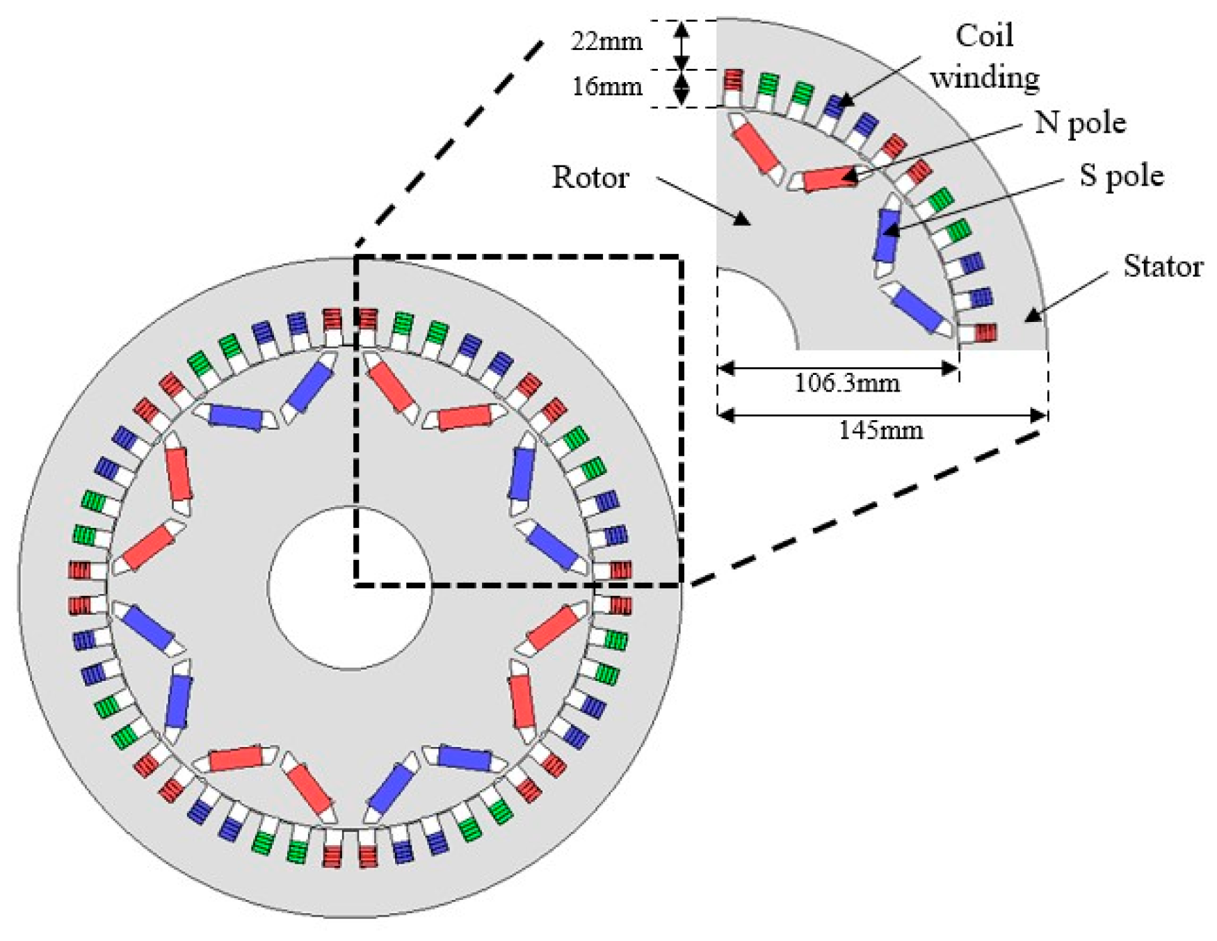
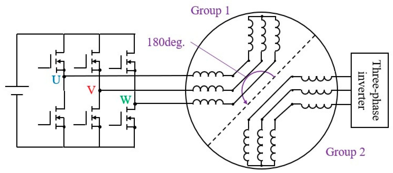
2.1. Proposed System

Figure 2 and Figure 3 show the configuration overview of the proposed system, and Table 1 shows the specifications of the motor. The proposed motor is intended for use in EVs and is based on an 8-pole, 48-slot permanent magnet synchronous motor (PMSM) to achieve a high output of 150 kW. Additionally, Figure 3 shows that the proposed motor is composed of two completely independent parallel inverters and windings. Therefore, intermittent operation is possible; that is, just one set of inverters and windings in parallel with a set of inverters and windings is used. Also, distributed winding is used to obtain a high power density.

2.2. Advantages and Disadvantages of the Proposed Motor

The proposed motor has the following advantages over existing units:
  • Improved control freedom;
  • Improved fault tolerance;
  • Lower voltage system.
The multiplexing of inverters and windings improves control freedom. This makes it possible to realize intentional intermittent operation and inverter thermal management.
In addition, the motor can continue to operate even if some inverters or windings fail, improving fault tolerance. Furthermore, in a two-parallel two-inverter system, the voltage of each inverter is reduced to 300 V compared to the 600 V system used in the conventional four-series configuration, so the surge voltage of the inverters is lower and partial discharges are less likely to occur.
Despite these advantages, there are also the following disadvantages:
  • Increased number of parts;
  • Increased cost;
  • Increase in harmonic current.
Increasing the number of inverters results in a higher number of components, increasing system complexity. Additionally, inverters use relatively expensive power semiconductors, raising concerns about cost increases due to the additional inverters. However, as described in the advantages, the voltage ratings of the power device can be reduced and the power device cost must be reduced. Furthermore, because the windings are arranged in two independent parallel configurations, the inductance of each winding will decrease and the impact of current harmonics will increase.

3. Achieving High-Efficiency Drive Using Intermittent Operation

3.1. Intermittent Operation Method

Figure 4 shows the drive system during intermittent operation. In the case of an eight-pole machine, four sets of three-phase winding in each pole pair (four pole pairs) are wound. These windings are connected either in parallel or in series and are connected with one inverter. The conventional winding is either two-series two-parallel or four-series windings, which is decided by the inverter voltage and current ratings. The proposed motor system also has two-series two-parallel windings; however, each set of two-series windings is connected with one inverter. Thus, intermittent operation in which only one group of two-series windings with one inverter is used is achieved as shown in Figure 4. On the other hand, as in the normal operation mode, each two groups of two-series windings are driven by two inverters simultaneously, the same as the conventional two-series two-parallel winding system. The mode change from normal operation to intermittent operation or vice versa is performed by simply changing the inverter voltage reference; the operating point for the mode change is pre-calculated depending on the motor and inverter loss shown in Section 4.

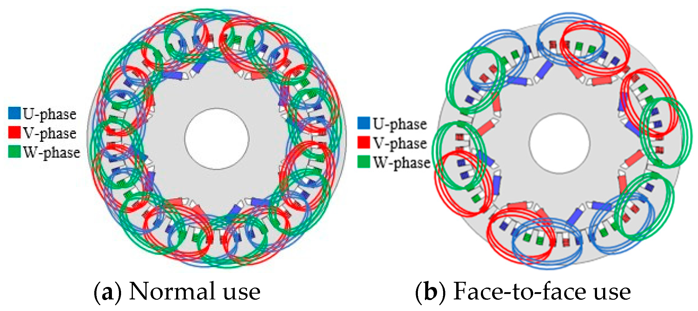
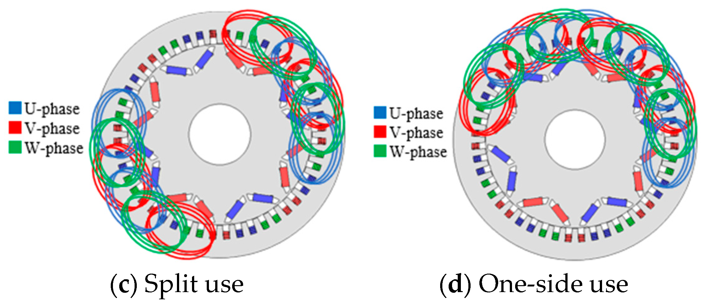
3.2. Winding Arrangement During Intermittent Operation

The winding arrangement used during normal operation is shown in Figure 5a; full pitch winding such as 2SPP (slots/pole/phase) is wound by wave winding. The winding arrangement proposals used during intermittent operation are shown in Figure 5b–d. Intermittent operation of the proposed motor can be achieved by extracting half of the coil set shown in Figure 5a and driving only the extracted coil set. Here, the coil set extraction patterns are broadly narrowed down to three, as shown in Figure 5b–d. The coil arrangement in Figure 5b is called face-to-face use, with the coils of each phase arranged facing each other, and the three-phase coils arranged dispersedly. This winding configuration distributes the magnetic field in a balanced manner throughout the stator. The coil arrangement in Figure 5c is called split use, with the three-phase coils of the coil arrangement in (b) arranged dispersed by 180 degrees for each pole pair. The magnetic field distribution is present, absent, present, absent every 90 degrees of mechanical angle. The coil arrangement in Figure 5d is called one-side use, with the coil arrangement in (c) combined on one side. The magnetic field distribution is present, present, absent, absent every 90 degrees of mechanical angle.

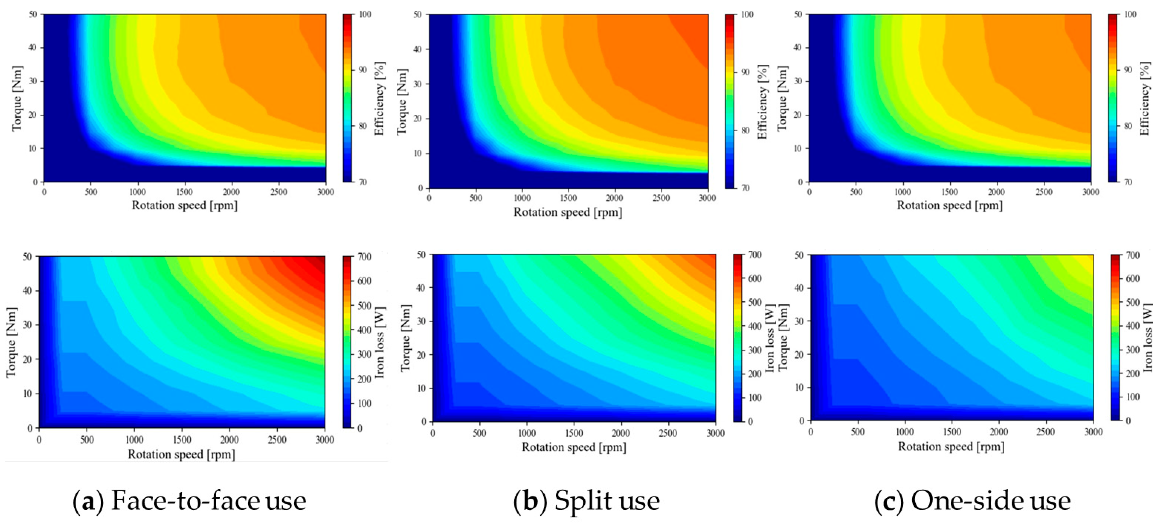
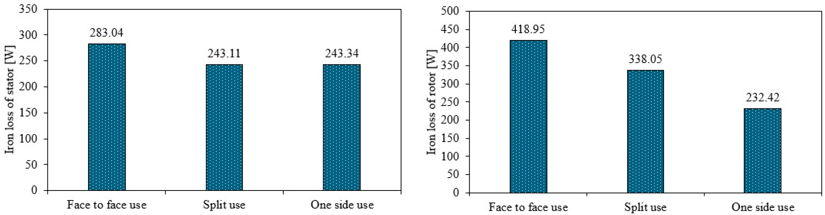
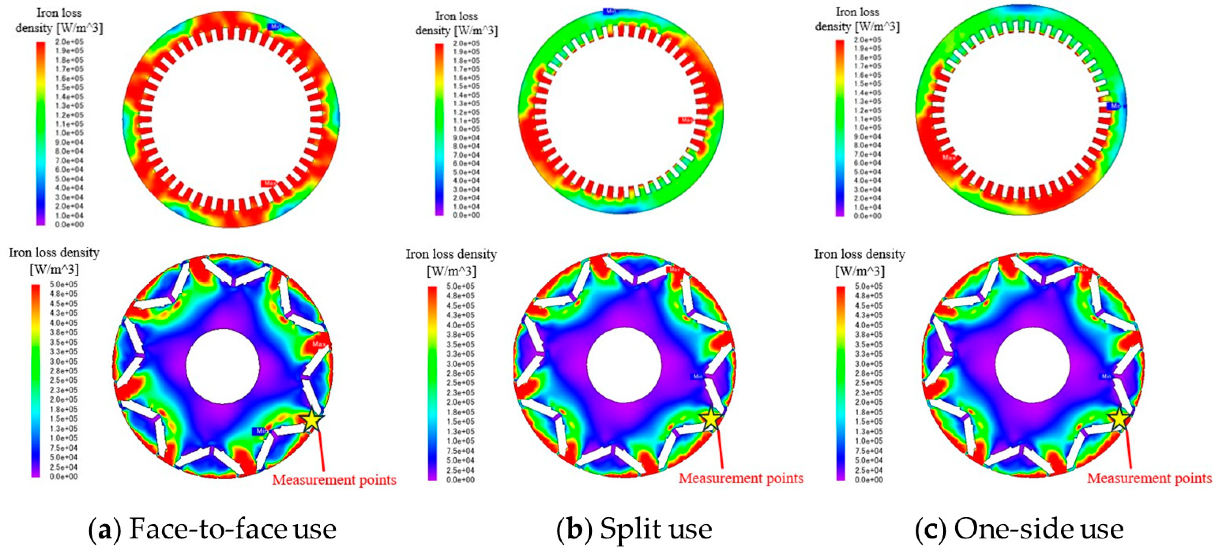
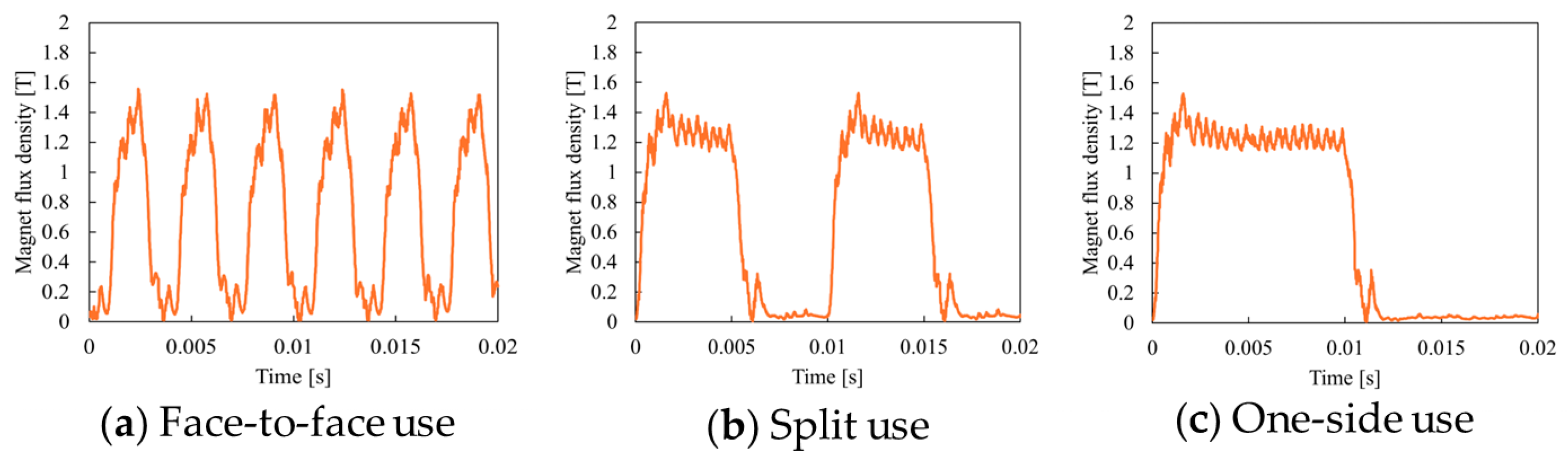
3.3. Comparison of Characteristic of Each Winding Layout Pattern

Through FEA (finite element analysis), we compared various characteristics for the winding arrangements in Figure 5b–d. The analysis conditions are shown in Table 2. JMAG@JRI is used for the FEA, the PWM voltage waveform in three phases is applied, and the copper loss, the iron loss, and the magnet eddy current loss are calculated from the obtained flux density and current. Especially the magnet eddy current loss analysis needs precise time stepping since the eddy current is generated by the differential of the flux density; we choose 10 μs, that is, 10 analyses in one PWM cycle. By using the input power, the output torque, and the losses at each operation point, the efficiency is calculated, and the efficiency map is obtained.
Figure 6 shows a comparison of the calculated efficiency maps and iron loss maps. The figure shows that the difference is particularly noticeable in the high-speed, high-load region, with one-side use being the most efficient and face-to-face use being the least efficient. The figure also shows a comparison of the iron loss maps. The difference is particularly noticeable in the high-speed, high-load region, with one-side use having the least iron loss and face-to-face use having the most iron loss. Regarding copper loss, the amount of winding is exactly the same in each winding pattern in Figure 5b–d, and the amount of current is also the same, so theoretically the copper loss should be the same in all regions. Therefore, the reason for the difference in efficiency in each winding pattern in Figure 5b–d is thought to be due to iron loss.
The iron loss of the motor is roughly described by the following equation.
P i r o n = V f B 2 K e + f B 2 K h d V
where P i r o n is the total iron loss [W],   f is the frequency, B is the magnetic flux density [T], K e is a constant of the eddy current loss, K h is a constant of the hysteresis loss, and V is the motor volume including the stator and the rotor. The first term of (1) represents the eddy current loss, which is proportional to the square of the flux density and frequency, and the second term of (2) represents the hysteresis loss. From (1), it is obvious that low iron loss can be achieved by decreasing the frequency and decreasing the volume, where the flux density generated under the amplitude of the flux density is the constant. Actually, FEA is necessary to calculate the iron loss because the flux density distribution cannot be calculated including the saturation phenomenon and skin effect, and the flux density includes harmonics. Then, we analyzed the flux density distribution by FEA and calculated the iron loss based on (1).
Figure 7 shows the comparison results of stator and rotor iron losses at high-load operating points (3000 rpm, 50 Nm). The figure shows that face-to-face use has the highest iron loss, and split use and one-side use have almost the same results in the stator. This can be explained using the flux density distribution. The flux density distributes over a large area of the stator in face-to face use because the winding distributes widely in the stator; also, the areas are similar between split use and one-side use (see Figure 8) because the winding is limited in the stator. However, the iron loss of the rotor is the smallest in one-side use and the largest in face-to-face use. This reason is explained using the rotor flux density phenomenon. Figure 9 shows the flux density transition (for one mechanical angle cycle) at the star mark in Figure 8. Figure 9 shows that the number of times the flux density changes during one mechanical angle cycle, that is, the frequency, is twice as high for one-side use and six-times as high for face-to-face use. Then from (1), we can see that especially the eddy current loss increases as the square of the frequency. Therefore, the differences in the frequency at which the magnetic flux density changes result in differences in eddy current loss, and it is thought that face-to-face use, where this frequency is the highest, has the greatest iron loss. From the above analyses, the one-side use construction for the stator winding is the most efficient for the intermittent drive.
The operating point is 3000 rpm, 50 Nm.

3.4. Efficiency Comparison Between Normal Operation and Intermittent Operation

Figure 10 shows the comparison of efficiency maps between normal operation and intermittent operation using one-side use. The figure shows that intermittent operation is more efficient especially in the low-speed and low-torque range. Figure 11 shows a comparison of various characteristics such as overall efficiency, total iron loss, permanent magnet eddy current loss, magnet joule loss, and copper loss for each output torque at a constant rotational speed of 500 rpm. The magnet joule loss is calculated by
W e d d y = 1 R P M d d t 2
where RPM is the electrical resistance of the permanent magnet and is the flux linkage into the magnet. The loss can be calculated by FEA that uses flux change of each calculated step.
Figure 11a shows that intermittent operation is more efficient up to an output torque of 50 Nm, and it is about 14.5% more efficient at a 5 Nm output, where the difference is the greatest; however, the efficiency difference becomes small as the output torque is increased. Figure 11b also shows that iron loss is reduced by up to 31% during intermittent operation compared to normal operation. Next, Figure 11c shows that the magnet joule loss generated by the eddy current is reduced by up to 60% during intermittent operation compared to normal operation. Finally, Figure 11d shows that the copper loss is larger during intermittent operation, and the difference becomes larger as the output torque increases. This is because when the same torque is output in normal operation and intermittent operation, intermittent operation requires twice the current because the amount of winding is smaller. Thus, the intermittent operation mode is suitable for use in the low-torque mode.
To further understand the reason why the iron loss and magnet joule loss are reduced, high-frequency losses by PWM voltage are broken down. It is well known that the PWM harmonics phase voltage Vm,n is generated as follows [25]:
V m , n = V d c 2 1 3 4 π 1 m sin m + n π 2 J n m π 2 M 2 sin n π 3
where Vdc is the DC voltage, M is the modulation depth, ω0 and ωc are the fundamental angular velocity and carrier angular velocity, respectively, and m and n are the carrier harmonic order and fundamental harmonic order, respectively. When the output torque is relatively low, the modulation depth M becomes around 0.5, the harmonics voltage of the ωc + 2ω0 (fc + 2f), 2ωc + ω0 (2fc + f), and 3ωc + 2ω0 (3fc + 2f) components especially becomes large as shown in Figure 12, and the resulting magnet joule loss by PWM harmonics becomes large.
Figure 13 shows high-frequency components of the iron loss (a) and magnet joule loss (b) at a 5 Nm output torque. The iron loss caused by PWM carrier harmonics is reduced by up to 68% and the magnet joule loss caused by PWM carrier harmonics is reduced by up to 64% during intermittent operation compared to normal operation. Further, Figure 14 shows the instantaneous values of the magnet joule loss density distribution and the stator iron loss density distribution under a light load condition (500 rpm,5 Nm). The figure shows that during intermittent operation, only half of the winding is used, so the joule loss and iron loss of the magnet occur only on the winding side in use. Also, by intermittent operation, the modulation index M becomes larger and the harmonics voltage amplitude becomes lower. For these reasons, it is thought that intermittent operation can reduce the magnet joule loss and iron loss caused by carrier harmonics compared to normal operation.

4. Comparison of Electricity Consumption Through Driving Simulation

4.1. System Efficiency Comparison

In the proposed system, the inverters and windings are configured in two parallel configurations, with all of them driven during normal operation and only one parallel inverter and winding driven during intermittent operation. As shown in the previous section, there is a difference in motor efficiency during normal operation and intermittent operation, especially in the low-load region. Therefore, we calculate the efficiency of the entire power unit, taking into account the inverter, and clarify the benefits of intermittent operation.

4.1.1. Method for Calculating Power Unit Efficiency

The efficiency of the entire power unit, including the motor and inverter, can be calculated using the following formula:
P o w e r   u n i t   e f f i c i e n c y   % = M o t o r   o u t p u t M o t o r   o u t p u t + M o t o r   l o s s + I n v e r t e r   l o s s   100
Motor output [W] = Te ωr
Motor loss [W] = copper loss + iron loss + magnet joule loss
In the above formula, the motor output is calculated by the output torque Te times the motor mechanical angular velocity ωr, the torque is outputted by FEA, and the angular velocity is set in FEA. The motor loss can use the analysis results obtained in the previous section, and the copper loss is calculated by the phase current that outputs the torque. Thus, it is necessary to obtain the inverter loss additionally. In this case, the inverter loss is calculated approximately as the sum of the losses of the switching elements. Here, the losses of the switching elements are divided into conduction loss and switching loss, which can be derived using the following formula:
W s w = 1 6 V D S I D f s w ( T R + T F )
W o n = D R D S o n I D 2
where W s w [W] is the switching loss, V D S [V] is the drain-source voltage, I D [A] is the drain current, f s w [Hz] is the switching frequency, T R [s] is the rise time, T F [s] is the fall time, W o n [W] is the conduction loss, D is the duty ratio, and R D S o n [Ω] is the drain-source on-resistance. The specifications and number of switching elements used in the loss calculation are shown in Table 3 and Table 4, respectively. From the above, the inverter loss is calculated from the current conditions at each operating point obtained by analysis in addition to Equations (7) and (8) and Table 3.

4.1.2. Power Unit Efficiency Comparison Results

Figure 15a,b show unit efficiency maps for normal and intermittent operation including the motor and the inverter losses. When comparing normal and intermittent operation, the latter is more efficient in low-load conditions, whereas normal operation is superior in other ranges. Figure 15c shows an efficiency map assuming that normal and intermittent operation can be freely switched between. As shown in Figure 15c, it is believed that the drive efficiency of the system can be enhanced by intentionally operating the system in intermittent operation in the low-load range and in normal operation in the high-load range. In the following sections; the driving mode shown in Figure 15a will be referred to as Mode 1, and the driving mode shown in Figure 15c will be referred to as Mode 2.

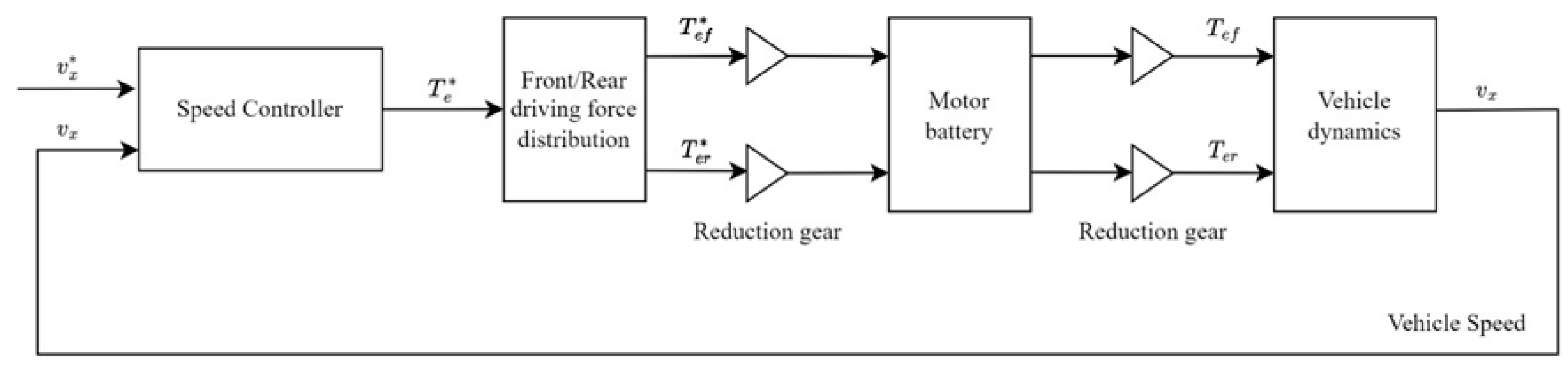
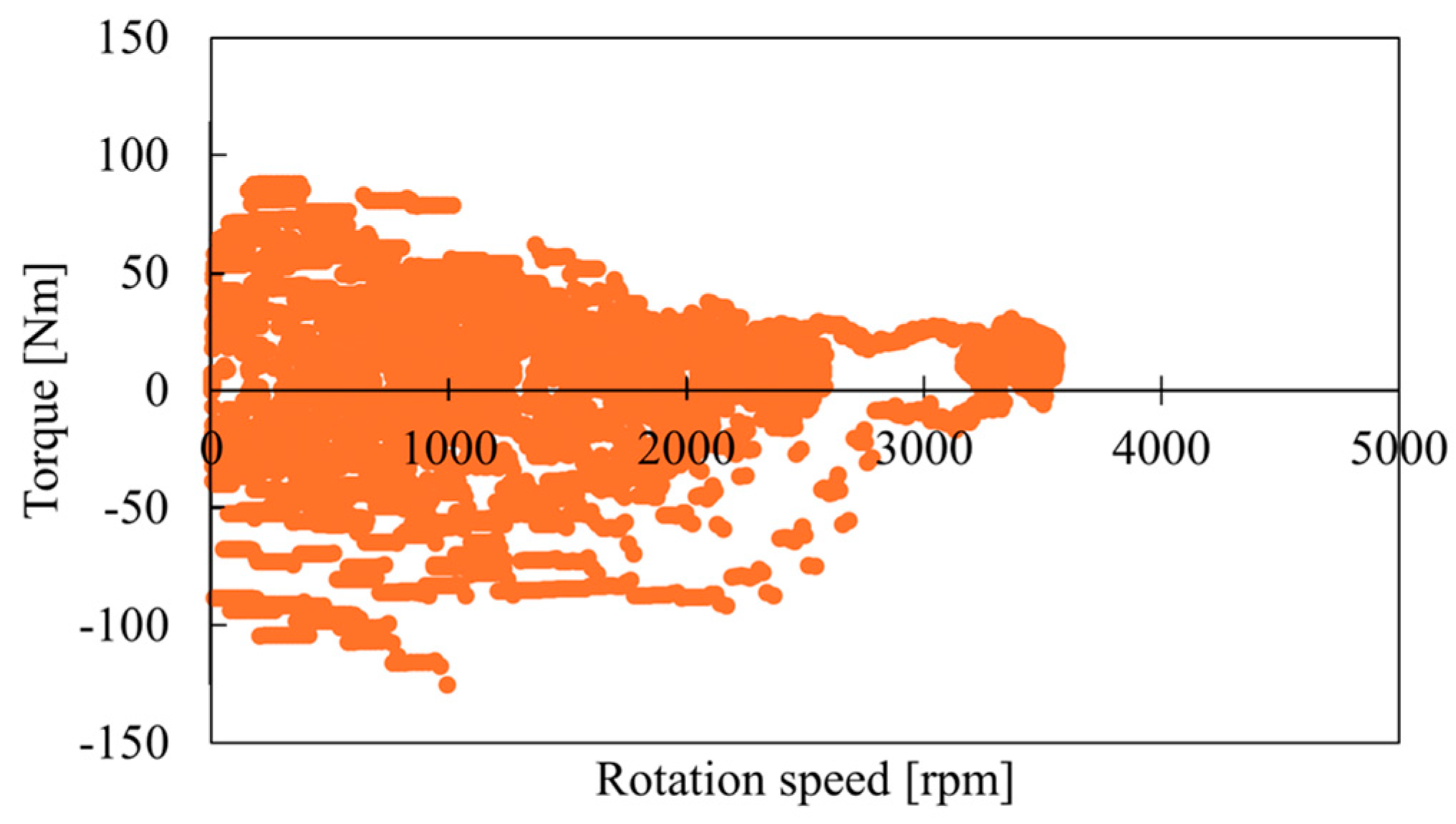
4.2. Verification of Power Consumption Through Vehicle Running Simulation

A vehicle-driving simulation is performed to compare the electric power consumption of the driving modes. Two cases are compared between only normal driving without intermittent driving (Mode 1) and a driving mode with intentional drive switching of normal driving and intermittent driving (Mode 2). The control block diagram for the vehicle simulation is shown in Figure 16; the control is simulated by Matlab/Simulink R2023b. In the figure, v x * is the speed command value, v x is the actual speed,   T e * is the torque command value, T e f * is the front wheel torque command value,   T e r * is the rear wheel torque command value, T e f is the front wheel output torque, and T e r is the rear wheel output torque. The efficiency map shown in Figure 16 is installed into the motor block in Figure 15. Table 4 shows the vehicle parameters and driving modes used; JE05 mode is used, that is, Japanese driving mode [27].
Figure 17 shows the simulation result of the operating point map in which the motor output is the torque when the vehicle runs the driving mode. Table 5 shows the simulation results for total electrical energy consumption and electricity cost, and Figure 18 shows the changes in total power consumption over time. Table 5 and Figure 18 show that Mode 2 consumes less total power than Mode 1, improving electricity consumption by about 9.0% in this simulation. Although the simulation result depends on the vehicle parameters and the loss map of the power train, we can say that Mode 2 operation has a possibility of improving the electrical energy consumption.

5. Conclusions

As EVs become more widespread, there is a demand for EV power units that are small and highly efficient. In this study, we proposed a multiple-inverter-drive method for an 8-pole, 48-slot distributed-winding IPMSM to improve motor efficiency, particularly through the proposed intermittent operation. Usually, intermittent operation is used only in the fault mode; however, the paper proposed that the mode should positively be used in the low-load region to improve efficiency. Since efficiency in intermittent operation is highly influenced by the stator winding topology, we compared some winding topologies and confirmed that the one-side winding arrangement was the most efficient during intermittent operation because the winding significantly reduced stator iron loss and magnet joule loss by the eddy current compared to other winding configurations. Finite element analysis that considered the PWM voltage waveform and the eddy current loss in the permanent magnet confirmed that this configuration minimized stator iron losses and magnet joule loss, contributing to improved energy efficiency in low-speed, low-torque conditions. Furthermore, a vehicle-driving simulation showed that strategic switching between normal and intermittent operation enhances overall power unit efficiency, leading to a reduction in electricity consumption by approximately 9.0% in the simulation. These findings indicate that intentional intermittent operation using a multiple-inverter system may be possible to improve the efficiency of EV power units. Based on these results, we expect that the proposed motor system will contribute to the widespread use of electric vehicles.
Further technical developments such as rotor optimization for the intermittent drive, a cooling method of both inverters and the motor, thermal control between multiple inverters, an integration method for the inverters with the motor, and so on are expected, and these results will be reported in the near future.

Author Contributions

Conceptualization, K.A.; methodology, K.T.; writing—original draft preparation, K.T.; writing—review and editing, K.A. All authors have read and agreed to the published version of the manuscript.

Funding

This research received no external funding.

Data Availability Statement

The original contributions presented in this study are included in the article. Further inquiries can be directed to the corresponding author.

Conflicts of Interest

The authors declare no conflict of interest.

References

  1. Hijikata, H.; Sakai, Y.; Akatsu, K.; Miyama, Y.; Arita, H.; Daikoku, A. Wide speed range operation by low-voltage inverter-fed 218 MATRIX motor for automobile traction motor. IEEE Trans. Power Electron. 2018, 33, 6887–6896. [Google Scholar] [CrossRef]
  2. Levi, E.; Bojoi, R.; Profumo, F.; Toliyat, H.A.; Williamson, S. Multiphase induction motor drives—A technology status review. IET Electr. Power Appl. 2007, 4, 489–516. [Google Scholar] [CrossRef]
  3. Zhao, Y.; Lipo, T.A. Space vector PWM control of dual three phase induction machine using vector space decomposition. IEEE Trans. Ind. Appl. 1995, 31, 1100–1109. [Google Scholar] [CrossRef]
  4. Barcaro, M.; Bianchi, N.; Magnussen, F. Faulty Operations of a PM Fractional-Slot Machine with a Dual Three-Phase Winding. IEEE Trans. Ind. Electron. 2011, 58, 3825–3832. [Google Scholar] [CrossRef]
  5. Yang, R.; Schofield, N.; Zhao, N.; Emadi, A. Dual three-phase permanent magnet synchronous machine investigation for battery electric vehicle power-trains. J. Eng. 2019, 2019, 3981–3985. [Google Scholar] [CrossRef]
  6. Karttunen, J.; Kallio, S.; Peltoniemi, P.; Silventoinen, P.; Pyrhönen, O. Decoupled Vector Control Scheme for Dual Three-Phase Permanent Magnet Synchronous Machines. IEEE Trans. Ind. Electron. 2014, 61, 2185–2196. [Google Scholar] [CrossRef]
  7. Demarcos, A.; Robles, E.; Ugalde, U.; Elosegui, I.; Andreu, J. Output Current Ripple in Electric Vehicles With Asymmetrical Dual Three-Phase Arrangement Applying Interleaved Carrier-Based PWM Techniques. IEEE Access 2025, 13, 41743–41767. [Google Scholar] [CrossRef]
  8. Yoshida, A.; Akatsu, K. Study of Winding Structure to Reduce Harmonic Currents in Dual 3-phase Motor. World Electr. Veh. J. 2023, 14, 100. [Google Scholar] [CrossRef]
  9. Demir, Y.; Aydin, M. A Novel Dual Three-Phase Permanent Magnet Synchronous Motor With Asymmetric Stator Winding. IEEE Trans. Magn. 2016, 52, 8105005. [Google Scholar] [CrossRef]
  10. Demir, Y.; Aydin, M. A Novel Asymmetric and Unconventional Stator Winding Configuration and Placement for a Dual Three-Phase Surface PM Motor. IEEE Trans. Magn. 2017, 53, 8111805. [Google Scholar] [CrossRef]
  11. Welchko, B.A. A Double-ended Inverter System for the Combined Propulsion and Energy Management Functions in Hybrid Vehicles with Energy Storage. In Proceedings of the 31st Annual Conference of IEEE Industrial Electronics Society, 2005. IECON 2005, Raleigh, NC, USA, 6–10 November 2005. [Google Scholar]
  12. Matsumori, H.; Maeda, Y.; Kosaka, T.; Matsui, N.; Saha, S. Dual Inverter-Fed Open Winding IPMSM Drive System for High-Power Premium Class EV. IEEE Trans. Ind. Appl. 2023, 59, 2069–2080. [Google Scholar] [CrossRef]
  13. Matsumori, H.; Kosaka, T.; Matsui, N.; Saha, S. Alternative PWM Switching Strategy Implementation for a Dual Inverter Fed Open Winding Motor Drive System for an Electric Vehicle Application. IEEE Trans. Ind. Appl. 2023, 59, 5957–5970. [Google Scholar] [CrossRef]
  14. Li, X.; Zhang, S.; Zhang, C.; Zhou, Y.; Zhang, C. An Improved Deadbeat Predictive Current Control Scheme for Open-Winding Permanent Magnet Synchronous Motors Drives With Disturbance Observer. IEEE Trans. Power Electron. 2021, 36, 4622–4632. [Google Scholar] [CrossRef]
  15. Yuan, X.; Zhang, C.; Zhang, S. Torque Ripple Suppression for Open-End Winding Permanent-Magnet Synchronous Machine Drives With Predictive Current Control. IEEE Trans. Ind. Electron. 2020, 67, 1771–1781. [Google Scholar] [CrossRef]
  16. Matsumori, H.; Kosaka, T.; Matsui, N.; Saha, S. Inverter Power Device Fault Detection and Fail Safe Action Strategy for Electric Vehicle With a Dual Inverter Fed Open Winding Motor. IEEE Trans. Ind. Appl. 2023, 59, 3875–3888. [Google Scholar] [CrossRef]
  17. An, Q.; Liu, J.; Peng, Z.; Sun, L.; Sun, L. Dual-Space Vector Control of Open-End Winding Permanent Magnet Synchronous Motor Drive Fed by Dual Inverter. IEEE Trans. Power Electron. 2016, 31, 8329–8342. [Google Scholar] [CrossRef]
  18. Dong, Y.; Zhang, S.; Zhang, C.; Li, X.; Zhao, M. A Robust Dual-Vector Model Predictive Current Control Scheme for Open-Winding Permanent Magnet Synchronous Motor Drives with Sliding Mode Observer. In Proceedings of the 2023 IEEE Energy Conversion Congress and Exposition (ECCE), Nashville, TN, USA, 29 October–2 November 2023; pp. 5235–5242. [Google Scholar] [CrossRef]
  19. Levi, E. Multiphase electrical machines for variable-speed applications. IEEE Trans. Ind. Electron. 2008, 55, 1893–1909. [Google Scholar] [CrossRef]
  20. Mori, M.; Mizuno, T.; Ashikaga, T.; Matsuda, I. A control method of an inverter-fed six-phase pole change induction motor for electric vehicles. In Proceedings of the Power Conversion Conference—PCC ‘97, Nagaoka, Japan, 6 August 1997; Volume 1, pp. 25–32. [Google Scholar] [CrossRef]
  21. Mallampalli, S.; Zhu, Z.Q.; Mipo, J.C.; Personnaz, S. Six-Phase Pole-Changing Winding Induction Machines with Improved Performance. IEEE Trans. Energy Convers. 2021, 36, 534–546. [Google Scholar] [CrossRef]
  22. Latif, T.; Agoro, S.; Jaffar, M.Z.M.; Husain, I. Control of a 4-Pole/2-Pole Electronic Pole-Changing Induction Motor for Traction Applications. IEEE Trans. Ind. Appl. 2023, 59, 6704–6714. [Google Scholar] [CrossRef]
  23. Yang, K.; Akatsu, K.; Okazaki, K.; Miyama, Y. Imbalanced Force Suppression Due to Static Eccentricity by Using Triple Three-phase Winding Motor. IEEJ J. Ind. Appl. 2023, 12, 763–772. [Google Scholar] [CrossRef]
  24. Yan, H.; Buticchi, G.; Yang, J.; Zhao, W.; Zhang, H.; Gerada, C. Active Thermal Control for Power Converters in Modular Winding Permanent Magnet Synchronous Motor. In Proceedings of the 2019 IEEE 13th International Conference on Compatibility, Power Electronics and Power Engineering (CPE-POWERENG), Sonderborg, Denmark, 23–25 April 2019; pp. 1–6. [Google Scholar]
  25. Miyama, Y.; Akatsu, K. Optimal Carrier Phase-shift Angle on Dual Three-Phase Windings Permanent Magnet Synchronous Motor. In Proceedings of the 2019 IEEE International Electric Machines & Drives Conference (IEMDC), San Diego, CA, USA, 12–15 May 2019; pp. 1362–1367. [Google Scholar] [CrossRef]
  26. Wolfspeed; C3M0015065K. Available online: https://www.wolfspeed.com/products/power/sic-mosfets/650v-silicon-carbide-mosfets/c3m0015065k/ (accessed on 9 July 2025).
  27. Japanese Test Cycle. Available online: https://dieselnet.com/standards/cycles/jp_je05.php (accessed on 9 July 2025).
Figure 1. Four categories of multiple-inverter-drive machines.
Wevj 16 00398 g001
Figure 2. Appearance of motor.
Wevj 16 00398 g002
Figure 3. Appearance of system.
Wevj 16 00398 g003
Figure 4. Intermittent operation method; positively only one set of inverter and winding is used.
Wevj 16 00398 g004
Figure 5. Winding arrangements for normal operation (a) and intermittent operation (bd).
Wevj 16 00398 g005aWevj 16 00398 g005b
Figure 6. Calculated efficiency map (upper) and iron loss contour (lower) in each winding method (ac).
Wevj 16 00398 g006
Figure 7. Stator iron loss (left) and rotor iron loss (right) comparison.
Wevj 16 00398 g007
Figure 8. Calculated iron loss density of the stator (upper) and the rotor (lower) in each winding method (ac). The operating point is 3000 rpm, 50 Nm.
Wevj 16 00398 g008
Figure 9. Rotor magnetic flux density change at the point shown in Figure 8.
Wevj 16 00398 g009
Figure 10. Comparison of efficiency maps between normal operation and intermittent operation using one-side use.
Wevj 16 00398 g010
Figure 11. Comparison of various characteristics such as overall efficiency, total iron loss, permanent magnet eddy current loss, magnet joule loss, and copper loss for each output torque at a constant rotational speed of 500 rpm.
Wevj 16 00398 g011
Figure 12. Ratio of carrier harmonic phase voltage amplitude to DC voltage versus modulation depth for the first- to fourth-carrier harmonics’ nearest sideband.
Wevj 16 00398 g012
Figure 13. Comparison of high-frequency losses by PWM voltage component: (a) iron loss and (b) magnet joule loss (500 rpm, 5 Nm).
Wevj 16 00398 g013
Figure 14. Loss density contour of magnet joule loss (a) and stator iron loss (b) for each component (500 rpm, 5 Nm).
Wevj 16 00398 g014
Figure 15. System efficiency maps for normal (a) and intermittent (b) operation; (c) shows the best efficiency by combining normal and intermittent operation.
Wevj 16 00398 g015
Figure 16. Control block diagram of vehicle-driving simulation.
Wevj 16 00398 g016
Figure 17. Motor operating point map when the vehicle runs the driving mode.
Wevj 16 00398 g017
Figure 18. Power consumption over time when the vehicle runs the mode. Mode 1 is normal operation; Mode 2 is combined operation.
Wevj 16 00398 g018
Table 1. Specifications of motor.
ParameterValue
Number of poles8
Number of slots48
Number of turns [turn/slot]4
Motor output [kW]150
Maximum voltage [V]150
Maximum current [Arms]400
Maximum torque [Nm]300
Maximum speed [rpm]17,000
Table 2. Finite element analysis conditions.
ParameterValue
Inverter DC voltage [V]300
PWM carrier frequency [kHz] 10
Rotation speed [rpm]50~3000
Phase current [A]0~200
Output torque [Nm]5~50
Table 3. Inverter specifications for the loss calculation.
ParameterValue
ModelC3M0015065K [26]
Maximum voltage [V]300
Maximum drain current [A]96
Rise/fall time [ns]32/15
On-resistance [mΩ]21
Table 4. Vehicle parameters and driving modes for the simulation.
ParameterValue
Vehicle typeHatchback
Drive systemAWD
Vehicle weight [kg]1000
Reduction ratio5
Coefficient drag0.601
Driving modeJE05 [27]
Table 5. Simulation results of driving.
ParameterMode1Mode2
Total electrical energy consumption [Wh]1387.61240.0
Electricity cost [km/kWh]10.0111.21
Disclaimer/Publisher’s Note: The statements, opinions and data contained in all publications are solely those of the individual author(s) and contributor(s) and not of MDPI and/or the editor(s). MDPI and/or the editor(s) disclaim responsibility for any injury to people or property resulting from any ideas, methods, instructions or products referred to in the content.

