
The Development of a 1 kW Mid-Range Wireless Power Transfer Platform for Autonomous Guided Vehicle Applications Using an LCC-S Resonant Compensator


Abstract
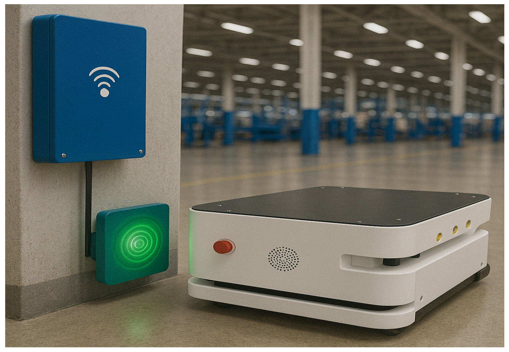
1. Introduction
2. Overview of Wireless Power Transfer
2.1. Resonant Compensation Topologies in Wireless Power Transfer for AGVs
2.2. The LCC-S Resonant Compensator Analysis
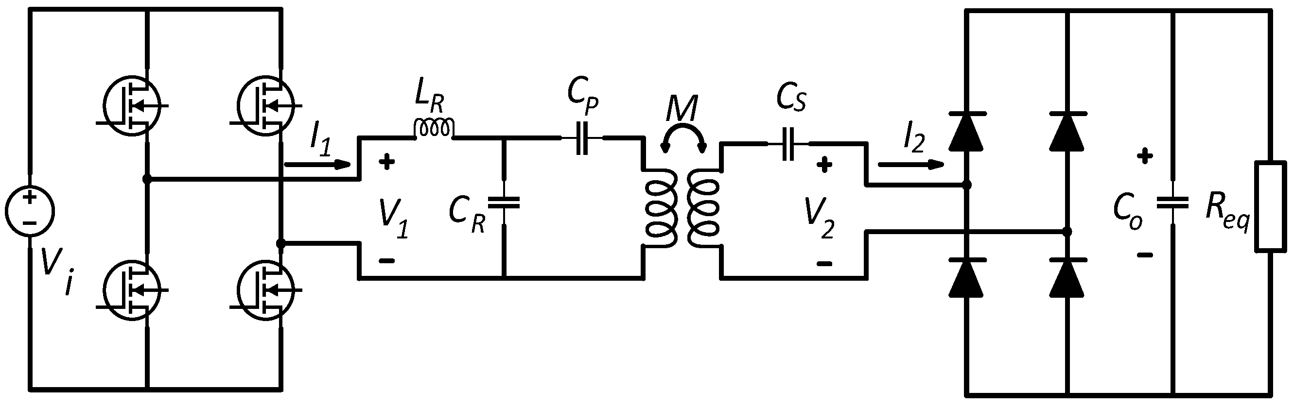
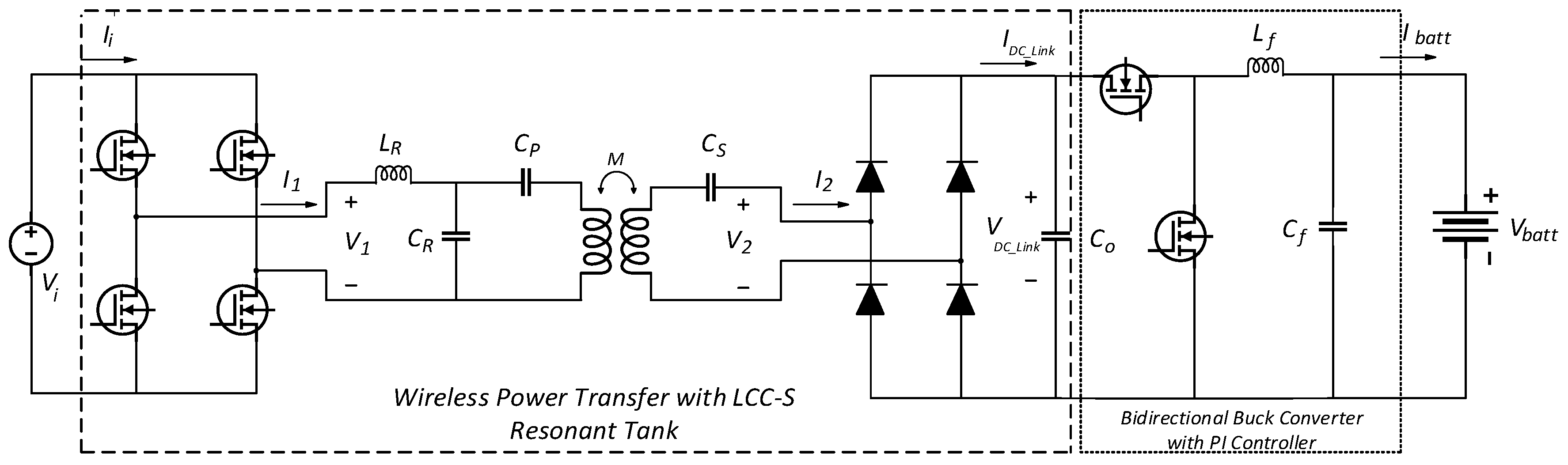
2.2.1. The WPT with an LCC-S Resonant Tank
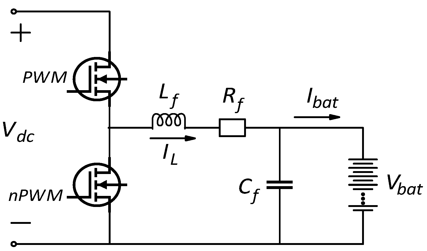
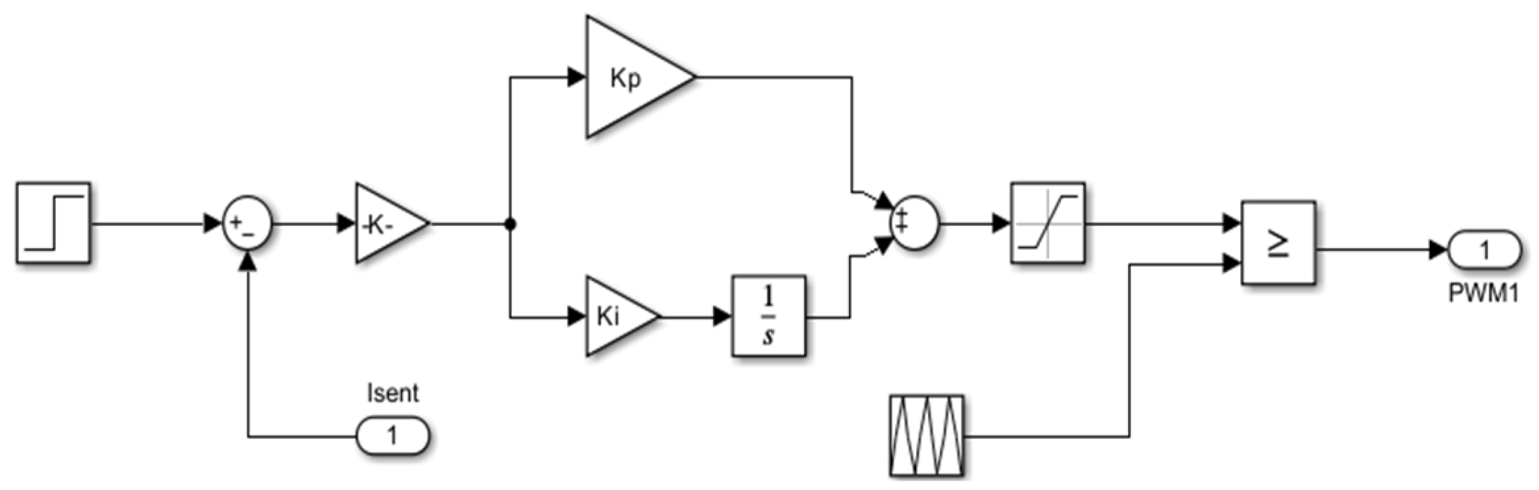
2.2.2. The Current Regulated dc-to-dc Buck Converter
3. Simulations of the Proposed Wireless System
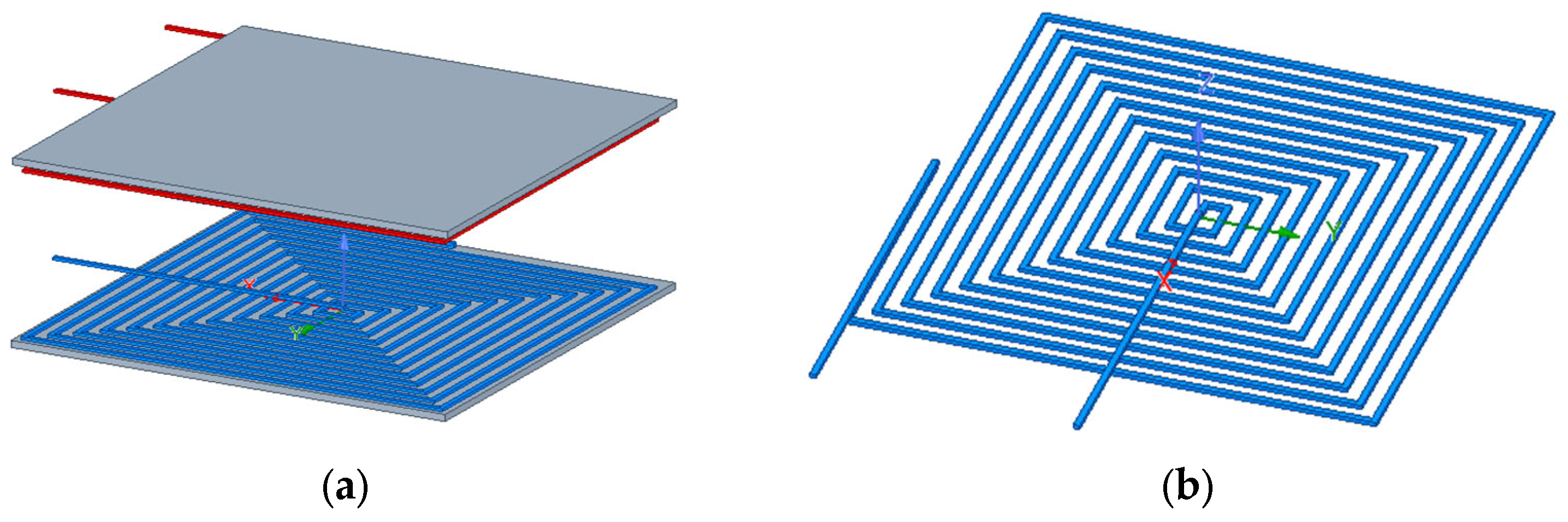
3.1. Simulation of WPT with LCC-S Resonant Tank
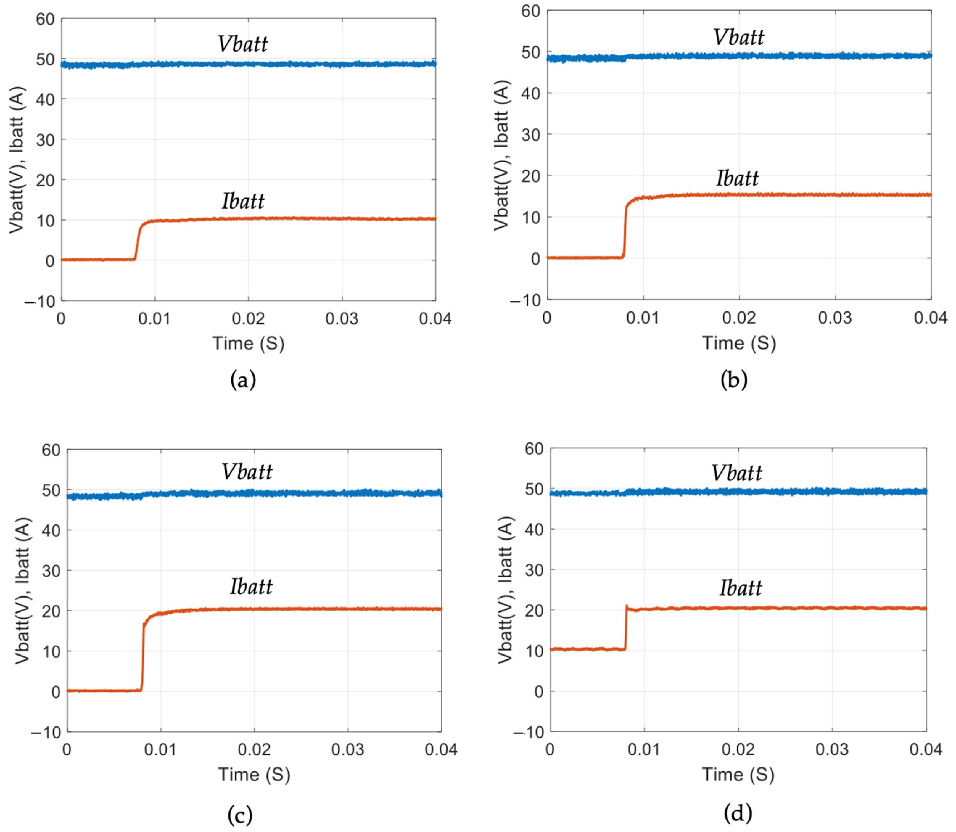
3.2. Simulation of dc-to-dc Buck Regulator Converter
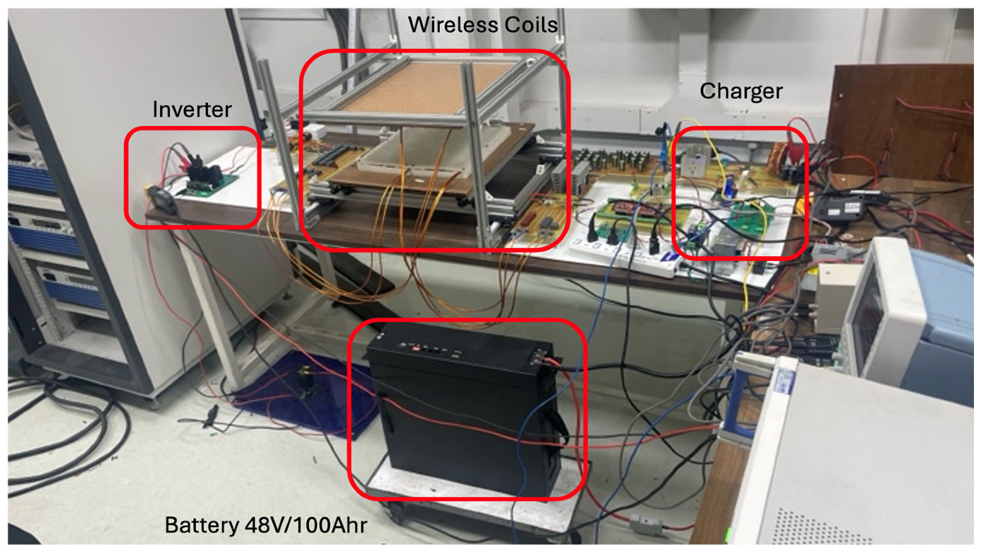
4. Hardware Implementation Analysis
5. Conclusions
Author Contributions
Funding
Data Availability Statement
Conflicts of Interest
Nomenclature
| ω | Angular frequency |
| Lr | Resonant inductor |
| Ls | Secondary coil |
| Lp | Primary coil |
| Cr | Resonant capacitor |
| Cp | Primary capacitor |
| Cs | Secondary capacitor |
| M | Mutual inductance |
| Kp | Proportional gain |
| Ki | Integral gain |
| Vbatt | Battery voltage |
| Ibatt | Battery current |
References
- Zhang, Z.; Pang, H.; Georgiadis, A.; Cecati, C. Wireless Power Transfer—An Overview. IEEE Trans. Ind. Electron. 2019, 66, 1044–1058. [Google Scholar] [CrossRef]
- Jiang, C.; Chau, K.T.; Liu, C.; Lee, C.H.T. An Overview of Resonant Circuits for Wireless Power Transfer. Energies 2017, 10, 894. [Google Scholar] [CrossRef]
- Wu, R.; Li, W.; Luo, H.; Sin, J.K.O.; Yue, C.P. Design and Characterization of Wireless Power Links for Brain–Machine Interface Applications. IEEE Trans. Power Electron. 2014, 29, 5462–5471. [Google Scholar] [CrossRef]
- Shinohara, N. Wireless power transmission progress for electric vehicle in Japan. In Proceedings of the 2013 IEEE Radio and Wireless Symposium, Austin, TX, USA, 20–23 January 2013; pp. 109–111. [Google Scholar] [CrossRef]
- Shanmugam, Y.; Narayanamoorthi, R.; Vishnuram, P.; Bajaj, M.; AboRas, K.M.; Thakur, P. A Systematic Review of Dynamic Wireless Charging System for Electric Transportation. IEEE Access 2022, 10, 133617–133642. [Google Scholar] [CrossRef]
- Maemura, M.; Kurpat, T.; Kimura, K.; Suzuki, T.; Hashimoto, T. Improvement of the Power Transfer Efficiency of a Dynamic Wireless Power Transfer System via Spatially Distributed Soft Magnetic Materials. In Proceedings of the 2022 Wireless Power Week (WPW), Bordeaux, France, 5–8 July 2022; pp. 332–337. [Google Scholar] [CrossRef]
- Mohamed, A.A.S.; Berzoy, A.; de Almeida, F.G.N.; Mohammed, O. Modeling and Assessment Analysis of Various Compensation Topologies in Bidirectional IWPT System for EV Applications. IEEE Trans. Ind. Appl. 2017, 53, 4973–4984. [Google Scholar] [CrossRef]
- Wen, F.; Chu, X.; Li, Q.; Gu, W. Compensation Parameters Optimization of Wireless Power Transfer for Electric Vehicles. Electronics 2020, 9, 789. [Google Scholar] [CrossRef]
- Ahire, D.B.; Gond, V.J.; Chopade, J.J. Compensation topologies for wireless power transmission system in medical implant applications: A review. Biosens. Bioelectron. X 2022, 11, 100180. [Google Scholar] [CrossRef]
- Shevchenko, V.; Husev, O.; Strzelecki, R.; Pakhaliuk, B.; Poliakov, N.; Strzelecka, N. Compensation Topologies in IPT Systems: Standards, Requirements, Classification, Analysis, Comparison and Application. IEEE Access 2019, 7, 120559–120580. [Google Scholar] [CrossRef]
- Venkatesan, M.; Rajamanickam, N.; Vishnuram, P.; Bajaj, M.; Blazek, V.; Prokop, L.; Misak, S. A Review of Compensation Topologies and Control Techniques of Bidirectional Wireless Power Transfer Systems for Electric Vehicle Applications. Energies 2022, 15, 7816. [Google Scholar] [CrossRef]
- Leng, Z.; Liu, Q. A simple model predictive control for Buck converter operating in CCM. In Proceedings of the 2017 IEEE International Symposium on Predictive Control of Electrical Drives and Power Electronics (PRECEDE), Pilsen, Czech Republic, 4–6 September 2017; pp. 19–24. [Google Scholar] [CrossRef]
- Xu, B.; Deng, J.; Gan, H.; Jiao, X.; Xu, Q.; Jiang, L. An Improved Model Predictive Control Approach for Wireless Power Transfer System of Electric Vehicles. In Proceedings of the 2023 2nd Asian Conference on Frontiers of Power and Energy (ACFPE), Chengdu, China, 20–22 October 2023; pp. 693–698. [Google Scholar] [CrossRef]
- Liu, X.; Suo, Y.; Zhang, Z.; Song, X.; Zhou, J. A New Model Predictive Current Control Strategy for Hybrid Energy Storage System Considering the SOC of the Supercapacitor. IEEE J. Emerg. Sel. Top. Power Electron. 2023, 11, 325–338. [Google Scholar] [CrossRef]
- Pirooz, A.; Noroozian, R. Model predictive control of classic bidirectional DC-DC converter for battery applications. In Proceedings of the 2016 7th Power Electronics and Drive Systems Technologies Conference (PEDSTC), Tehran, Iran, 16–18 February 2016; pp. 517–522. [Google Scholar] [CrossRef]
- Morel, C.; Guignard, J.-C.; Guillet, M. Sliding mode control of DC-to-DC power converters. In Proceedings of the 9th International Conference on Electronics, Circuits and Systems, Dubrovnik, Croatia, 15–18 September 2002; Volume 3, pp. 971–974. [Google Scholar] [CrossRef]
- Romero, A.; Martinez-Salamero, L.; Valderrama, H.; Pallas, O.; Alarcon, E. General purpose sliding-mode controller for bidirectional switching converters. In Proceedings of the 1998 IEEE International Symposium on Circuits and Systems (ISCAS), Monterey, CA, USA, 31 May–3 June 1998; Volume 6, pp. 466–469. [Google Scholar] [CrossRef]
- Agarwal, A.; Deekshitha, K.; Singh, S.; Fulwani, D. Sliding mode control of a bidirectional DC/DC converter with constant power load. In Proceedings of the 2015 IEEE First International Conference on DC Microgrids (ICDCM), Atlanta, GA, USA, 7–10 June 2015; pp. 287–292. [Google Scholar] [CrossRef]
- Kayaalp, R.İ.; Demirdelen, T.; Tümay, M. A novel fuzzy logic control for bidirectional DC-DC converter and comparison with dual phase-shift control method in medium voltage applications. In Proceedings of the 2016 IEEE International Conference on Computational Intelligence and Virtual Environments for Measurement Systems and Applications (CIVEMSA), Budapest, Hungary, 27–28 June 2016; pp. 1–6. [Google Scholar] [CrossRef]
- Yusoff, M.J.; Ismail, N.F.N.; Musirin, I.; Hashim, N.; Johari, D. Comparative study of Fuzzy Logic controller and Proportional Integral Derivative controller on DC-DC Buck Converter. In Proceedings of the 2010 4th International Power Engineering and Optimization Conference (PEOCO), Shah Alam, Malaysia, 23–24 June 2010; pp. 142–148. [Google Scholar] [CrossRef]
- Suyata, T.I.; Mungporn, P.; Yodwong, B.; Phattanasak, M.; Thounthong, P.; Jamshidpour, E.; Pierfederici, S.; Nahid-Mobarakeh, B.; Bizon, N.; Inteeworn, R.; et al. Improved Damping Control Based on Hamiltonian-Energy Function with State-Observer for Permanent Magnet Synchronous Motor Drives. In Proceedings of the 2023 IEEE Transportation Electrification Conference and Expo, Asia-Pacific (ITEC Asia-Pacific), Chiang Mai, Thailand, 28 November–1 December 2023; pp. 1–6. [Google Scholar] [CrossRef]
- Buaket, W.; Pongyart, W. A port-Hamiltonian Approach in Current Controller Design for Buck Boost Converter. In Proceedings of the 2022 International Electrical Engineering Congress (iEECON), Khon Kaen, Thailand, 9–11 March 2022; pp. 1–4. [Google Scholar] [CrossRef]
- Mungporn, P.; Khomfoi, S.; Inteeworn, R.; Gonmanee, A.; Pierfederici, S.; Nahid-Mobarakeh, B.; Takorabet, N.; Bizon, N.; Yodwong, B.; Thounthong, P. Hamiltonian-Differential Flatness Control Laws for Battery/Ultracapacitor for Hybrid Electric Vehicle Applications. In Proceedings of the 2023 IEEE Transportation Electrification Conference and Expo, Asia-Pacific (ITEC Asia-Pacific), Chiang Mai, Thailand, 28 November–1 December 2023; pp. 1–6. [Google Scholar] [CrossRef]
- Chen, Y.; Zhang, H.; Park, S.-J.; Kim, D.-H. A Switching Hybrid LCC-S Compensation Topology for Constant Current/Voltage EV Wireless Charging. IEEE Access 2019, 7, 133924–133935. [Google Scholar] [CrossRef]
- Ali, N.; Liu, Z.; Hou, Y.; Armghan, H.; Wei, X.; Armghan, A. LCC-S Based Discrete Fast Terminal Sliding Mode Controller for Efficient Charging through Wireless Power Transfer. Energies 2020, 13, 1370. [Google Scholar] [CrossRef]
- Wang, W.; Deng, J.; Chen, D.; Wang, Z.; Wang, S. A Novel Design Method of LCC-S Compensated Inductive Power Transfer System Combining Constant Current and Constant Voltage Mode via Frequency Switching. IEEE Access 2021, 9, 117244–117256. [Google Scholar] [CrossRef]
- Wang, S.; Wei, B.; Bo, Q.; Xu, C.; Xu, J. Analysis of Output Characteristics of LCC-C Inductively Coupled Power Transfer System. In Proceedings of the 2019 IEEE 3rd International Electrical and Energy Conference (CIEEC), Beijing, China, 7–9 September 2019; pp. 845–850. [Google Scholar] [CrossRef]
- Zhao, R.; Xu, F. Design of Wireless Power Transfer System Based on LCC-S. J. Phys. 2023, 2496, 012014. [Google Scholar] [CrossRef]
- Geng, Y.; Li, B.; Yang, Z.; Lin, F.; Sun, H. A High Efficiency Charging Strategy for a Supercapacitor Using a Wireless Power Transfer System Based on Inductor/Capacitor/Capacitor (LCC) Compensation Topology. Energies 2017, 10, 135. [Google Scholar] [CrossRef]
- Solimene, L.; Corti, F.; Musumeci, S.; Reatti, A.; Ragusa, C.S. A controlled variable inductor for an LCC-S compensated Wireless Power Transfer system. In Proceedings of the IECON 2022—48th Annual Conference of the IEEE Industrial Electronics Society, Brussels, Belgium, 17–20 October 2022; pp. 1–6. [Google Scholar] [CrossRef]
- SAE J2954; Wireless Power Transfer for Light-Duty Plug-in/Electric Vehicles and Alignment Methodology. SAE International: Warrendale, PA, USA, 2020.


| Topology | Advantages | Disadvantages |
|---|---|---|
| SS (Series–Series) | - Simple structure - Easy to design and control - Good voltage gain at resonance | - Output depends on load - Poor regulation - Sensitive to coil misalignment |
| SP (Series–Parallel) | - Load-independent voltage source behavior - Better voltage regulation | - Cannot achieve ZVS easily - High circulating current - Poor efficiency at light load |
| PS (Parallel–Series) | - Load-independent current source - Suitable for constant current applications | - Requires large capacitors - Difficult to maintain ZVS - Sensitive to misalignment |
| PP (Parallel–Parallel) | - Output current relatively stable under load variations - Constant current profile possible | - Poor ZVS conditions - Complex tuning - High component stress |
| LCC-S (LCC-Series) | - Output current relatively stable under load variations - Constant current profile possible | - More complex structure - Requires precise tuning - Slightly higher cost and size |
| Aspect | PI Controller | Modern Controllers (MPC, Adaptive, SMC, Fuzzy) |
|---|---|---|
| Implementation Complexity | Simple, easy to implement in low-end microcontrollers | Complex, requires advanced algorithms and more computation |
| Cost | Low cost (minimal hardware/software) | Higher cost due to processing, memory, or sensor requirements |
| Tuning | Manual tuning | Self-tuning (Adaptive), rule-based (Fuzzy), or predictive (MPC) |
| Robustness to Nonlinearity | Weak—performance drops with battery nonlinearity or misalignment | Strong—effectively handles system nonlinearity and parameter variation |
| Suitability for Real-Time Dynamic Charging | Limited—may overshoot or be unstable with rapid SOC changes | Excellent—tracks dynamic charging profiles (e.g., fast charging from 0 to 20 A) |
| Industrial Use Case Readiness | Common in low-cost applications with stable operation | Used in advanced, high-performance systems (but still maturing for WPT) |
| Parameter | Value |
|---|---|
| Primary/secondary self-inductance | 32.66/32.56 µH |
| Mutual inductance | 5.4 µH |
| Operating distance | 15 cm |
| Coil type/size | Rectangular/30 cm × 30 cm |
| Parameter | Value |
|---|---|
| Input Voltage | 200 V ± 5% |
| Output Voltage | 120 V ± 5% |
| Output Power | 1 kW ± 5% |
| Switching Frequency | 85k Hz ± 1% |
| Compensators | Value |
|---|---|
| Lr | 8.56 μH ± 2% |
| Cr | 409.25 nF ± 2% |
| Co | 40.85 μF ± 2% |
| Cp | 149.61 nF ± 2% |
| Cs | 109.56 nF ± 2% |
Disclaimer/Publisher’s Note: The statements, opinions and data contained in all publications are solely those of the individual author(s) and contributor(s) and not of MDPI and/or the editor(s). MDPI and/or the editor(s) disclaim responsibility for any injury to people or property resulting from any ideas, methods, instructions or products referred to in the content. |
© 2025 by the authors. Published by MDPI on behalf of the World Electric Vehicle Association. Licensee MDPI, Basel, Switzerland. This article is an open access article distributed under the terms and conditions of the Creative Commons Attribution (CC BY) license (https://creativecommons.org/licenses/by/4.0/).
Share and Cite
Pairindra, W.; Phongsawat, S.; Phophongviwat, T.; Khomfoi, S. The Development of a 1 kW Mid-Range Wireless Power Transfer Platform for Autonomous Guided Vehicle Applications Using an LCC-S Resonant Compensator. World Electr. Veh. J. 2025, 16, 322. https://doi.org/10.3390/wevj16060322
Pairindra W, Phongsawat S, Phophongviwat T, Khomfoi S. The Development of a 1 kW Mid-Range Wireless Power Transfer Platform for Autonomous Guided Vehicle Applications Using an LCC-S Resonant Compensator. World Electric Vehicle Journal. 2025; 16(6):322. https://doi.org/10.3390/wevj16060322
Chicago/Turabian StylePairindra, Worapong, Suwaphit Phongsawat, Teeraphon Phophongviwat, and Surin Khomfoi. 2025. "The Development of a 1 kW Mid-Range Wireless Power Transfer Platform for Autonomous Guided Vehicle Applications Using an LCC-S Resonant Compensator" World Electric Vehicle Journal 16, no. 6: 322. https://doi.org/10.3390/wevj16060322
APA StylePairindra, W., Phongsawat, S., Phophongviwat, T., & Khomfoi, S. (2025). The Development of a 1 kW Mid-Range Wireless Power Transfer Platform for Autonomous Guided Vehicle Applications Using an LCC-S Resonant Compensator. World Electric Vehicle Journal, 16(6), 322. https://doi.org/10.3390/wevj16060322