Article

A Symmetrical Cross Double-D Coil with Improved Misalignment Tolerance for WPT Systems

1
Department of Electrical Engineering, Tennessee Tech University, Cookeville, TN 38505, USA
2
Center for Energy System Research, Tennessee Tech University, Cookeville, TN 38505, USA
3
Bonitron, Inc., Nashville, TN 37211, USA
*
Author to whom correspondence should be addressed.
World Electr. Veh. J. 2025, 16(7), 405; https://doi.org/10.3390/wevj16070405
Submission received: 27 April 2025 / Revised: 8 July 2025 / Accepted: 15 July 2025 / Published: 18 July 2025
(This article belongs to the Special Issue Wireless Power Transfer Technology for Electric Vehicles)

Abstract

Inductive Wireless Power Transfer (WPT) technologies are advancing significantly in the electric vehicle (EV) charging applications. Misalignment between transmitting and receiving coils can considerably affect power transmission efficiency in WPT systems. Prior research involved power electronics as well as electromagnetic couplers. This work focuses on the coil design aspect of electromagnetic couplers. A relatively new concept of Symmetrical Cross Double-D (SCDD) type of the coil design is introduced specifically to maximize tolerance to misalignment while sustaining significant amount of power transferred. Mutual inductance was determined for the perfect alignment and misalignment positions of the SCDD coils. Mutual inductance obtained from the simulation was validated from the experimental measurements. The SCDD electromagnetic coupler demonstrated almost 2.5 times superior tolerance to misalignment of coils compared to the conventional circular coupler while maintaining at least 78% of maximum power transfer even at a lateral misalignment of 40 mm.

1. Introduction

Inductive Power Transfer (IPT) technology is an emerging alternative to traditional conductive charging methods. Its popularity is primarily due to multiple advantages- eliminating bulky cables, minimizing the risk of electric shocks, and enhancing overall convenience. In an inductive WPT system, fast and efficient charging is facilitated via optimized mutual inductance by keeping stray electromagnetic fields within safe prescribed limits given by International Commission on Non-Ionizing Radiation Protection [1]. Variation in power transfer efficiency due to coil misalignment is a critical challenge. Any misalignment alters the mutual inductance between transmitter and receiver coils and degrades the system performance [2]. Optimal design of power pads alias electromagnetic couplers is very crucial in minimizing misalignment issues. Several pad topologies have been explored over the years to improve misalignment tolerance and ensure consistent power delivery. The Double D (DD) pad has been widely adopted and studied for its relatively higher tolerance to misalignment compared to conventional circular pads [3,4,5,6] albeit with increased stray field emissions. In [7], researchers proposed an optimized pad geometry having a single-row arrangement of three DD coils. This design significantly improved power transfer under misaligned conditions. This arrangement, however, suffers from increased cost, system complexity, additional copper requirements, and need for extra control circuitry. A hybrid configuration was developed in [8] with four rectangular coils and an auxiliary driving coil. This design markedly improved misalignment tolerance and was found suitable for biomedical applications. Like the previous work, however, the system relied heavily on supplementary power electronics for control and switching, which increased the cost and posed practical implementation challenges. A Tripolar Plane-Type (TPT) transmitter was developed in [9] that could minimize bulkiness. This novel transmitter could facilitate 3D omnidirectional power transfer within a 2D form factor. Such a technical advancement addressed size constraints found in earlier bowl-type designs. Though this TPT model could withstand angular misalignments, the design demands multiple converters and compensation networks at an additional cost.
The two innovative control strategies were proposed for a communication-free WPT system in [10]. This method overcame a heavy dependence on wireless communication that could cause latency and interference. The control scheme avoids wireless feedback through an estimation of secondary-side parameters from primary side measurements to support constant current and voltage charging [10]. The conduction angle method showed superior system performance with minimal cost burden and simplicity in design. Another novel design to address existing design limitations was proposed in [11]. The authors proposed embedding tertiary coils into the main square coil to shift the magnetic field in the misalignment direction. This design enhanced mutual inductance and coupling coefficient. The developed misalignment detection circuit and circuit polarity arranger allowed the transmitter to dynamically adapt based on the receiver’s position. The prototype system achieved relatively stable power output with 5% variation under a 60 mm lateral offset and 100 mm air gap. This design demonstrated high efficiency and robustness while minimizing power fluctuations during coil misalignment. However, the added circuit complexity may increase cost and design effort.
A wireless power transfer system having fractional-order was developed in the context of autonomous operation [12]. This design overcame dependence on coupling strength and inaccuracies caused by sampling distorted voltage signals. Authors shifted control parameters from the fractional-order capacitor (FOC) to the inverter for more stable power delivery without relying on complex FOC behavior. The improved primary-side control approach simplified the system, reduced sampling errors and eliminated coupling strength-related limitations. Combining the double-D and circular pad structures was another design improvement researched to improve misalignment tolerance by reducing field leakage [13]. Such an arrangement reported higher coupling efficiency compared to conventional double DD and circular pads (DDC) under horizontal and vertical displacement. The DDC pad design aligns well with SAE J2954 standards for wireless EV charging. A comprehensive review of advancements in high-power inductive WPT designs for e-mobility applications, including electric buses and ships was presented in [14]. This review covered theoretical models, compensation topologies, and coil design optimizations suitable for increasing power transfer capability. A comparison of four planar coil types—circular, square, bipolar, and rectangular—highlighted their trade-offs in efficiency, material usage, and misalignment handling. The review emphasized advantages of SiC MOSFET-based converters and S-S (series-series) compensation networks in efficiently delivering power above 22 kW. The review may serve as a foundational reference for designing scalable and safe high-power inductive WPT systems. A new system using an intermediate coil and dual decoupled receivers was proposed in [15]. This design addressed lateral and vertical coil displacement by isolating cross-coupling effects via a reactance canceling principle [16]. With this topology, the system maintained constant current output even when the receiver moved significantly from the center, achieving ±210 mm X-axis and up to 60 mm Z-axis tolerance with less than ±5% current fluctuation. The intermediate coil also restricted the inverter current during severe misalignment, preventing system instability. This design is particularly promising for large-scale applications where the receiver position cannot be precisely controlled.
A fully optimized and shielded DD coil structure aligned with SAE J2954 standards for high-power EV charging. ferrite cores and EMF shielding was presented in [17]. Ref. [18] proposed a WPT system for the rectangular coil misalignment with S-S and LCC-LCC compensation networks. However, these papers used complex circuit, utilized more components for compensation, involves complex networks. These works also utilizes Ferrite and Shielded, and requires additional circuit control systems for actively tracking and taking the feedback signals that regularly updates to synchronize the resonant frequency. Additionally, four different error amplifier controllers were employed to control the system and used for generating the logic switching sequences. This paper avoids additional circuit as well as error amplifier controllers. The proposed SCDD - without any ferrite or shielding-offers potentially a more suitable for real-world dynamic applications such as ’dynamic EV wireless charging’ and ’Drone charging pads’, where reliable power transfer even under slight misalignment is essential. The coil designs presented in [19,20] both include transmitter and receiver geometries that are different from each other. This leads to only partial transmission/reception of the power at any given time. The proposed design in this paper has identical transmitter and receiver coils thoroughly engaging in the maximum coupling in the array formation.
The Symmetrical Cross Double-D (SCDD) pad is a balanced solution for addressing bulkiness and misalignment challenges. This design has a single, multi-turn coil wound in a cross-DD layout. It mimics the performance of four rectangular coils in which two Double-D coils placed perpendicularly, form a cross-like shape. The SCDD pad has a relatively low cost and less complexity due to its minimal power converter and compensation networks. Constructive interference in the SCDD pad leads to strong central coupling, allowing it to maintain effective performance even when there is misalignment along the longitudinal (X-axis) and lateral (Y-axis) directions. It is featured with minimal stray fields due to peripheral field cancellation. Thus, SCDD pad offers an efficient and compact alternative for inductive WPT systems.
Major contributions presented in this paper are as follows. A new SCDD coupler coil is introduced for improving output power under misalignment conditions for WPT systems. Magnetic field for different geometries are simulated, analyzed and compared with the proposed SCDD coil. Comparison is made for the coefficient of coupling between Double-D and SCDD under different misalignment distances along Y-axis of the geometry. In addition, the experimental results are validated for the proposed SCDD system by comparing the commonly used circular pad system.

2. Inductive WPT System Development

In dynamic wireless power transfer (WPT) applications like electric vehicles (EVs), the driver’s ability to keep the vehicle within the designated alignment zone plays a crucial role in minimizing the negative effects of longitudinal (X-axis) and lateral (Y-axis) misalignment caused by vehicle motion, as illustrated in Figure 1. The tolerance of a coil implementation to such misalignments can be evaluated using several parameters, such as mutual inductance, coupling coefficient and overall system efficiency. The wireless power transfer system in this work is based on the progressive enhancement of the coil structure. Three types of coil configuration are explored: Single-D, Double-D and Symmetrical Cross Double-D with a current excitation of 10A. ANSYS Electronics Desktop (https://www.ansys.com/products/electronics (accessed on 15 April 2025)) is used to implement and simulate each of these coils.

2.1. Single-D Coupler

Single-D Coupler implementation is the most basic arrangement consisting of transmitter and receiver with single loop D-shaped geometry. This coil is rectangular in shape, with dimensions of 280 mm in length and 240 mm in width. The coil consists of 15 turns and wire used to make coil has the diameter of 3 mm. The coils are 5 mm apart from each other. The coil is implemented in the X-Y plane, and its geometry is illustrated in the corresponding Figure 2a.

2.2. Double -D Coupler

By adding two identical single-D coils placed side by side as shown in Figure 2b, the Double-D (DD) coil configuration expands on the fundamental single D-shaped coupler. Each coil looks like a D and is a rectangular winding that is 560 mm in length and 240 mm width. Copper wire diameter, winding turns, and the gap among the positions of the coil are employed similar to that of Single-D Coupler.

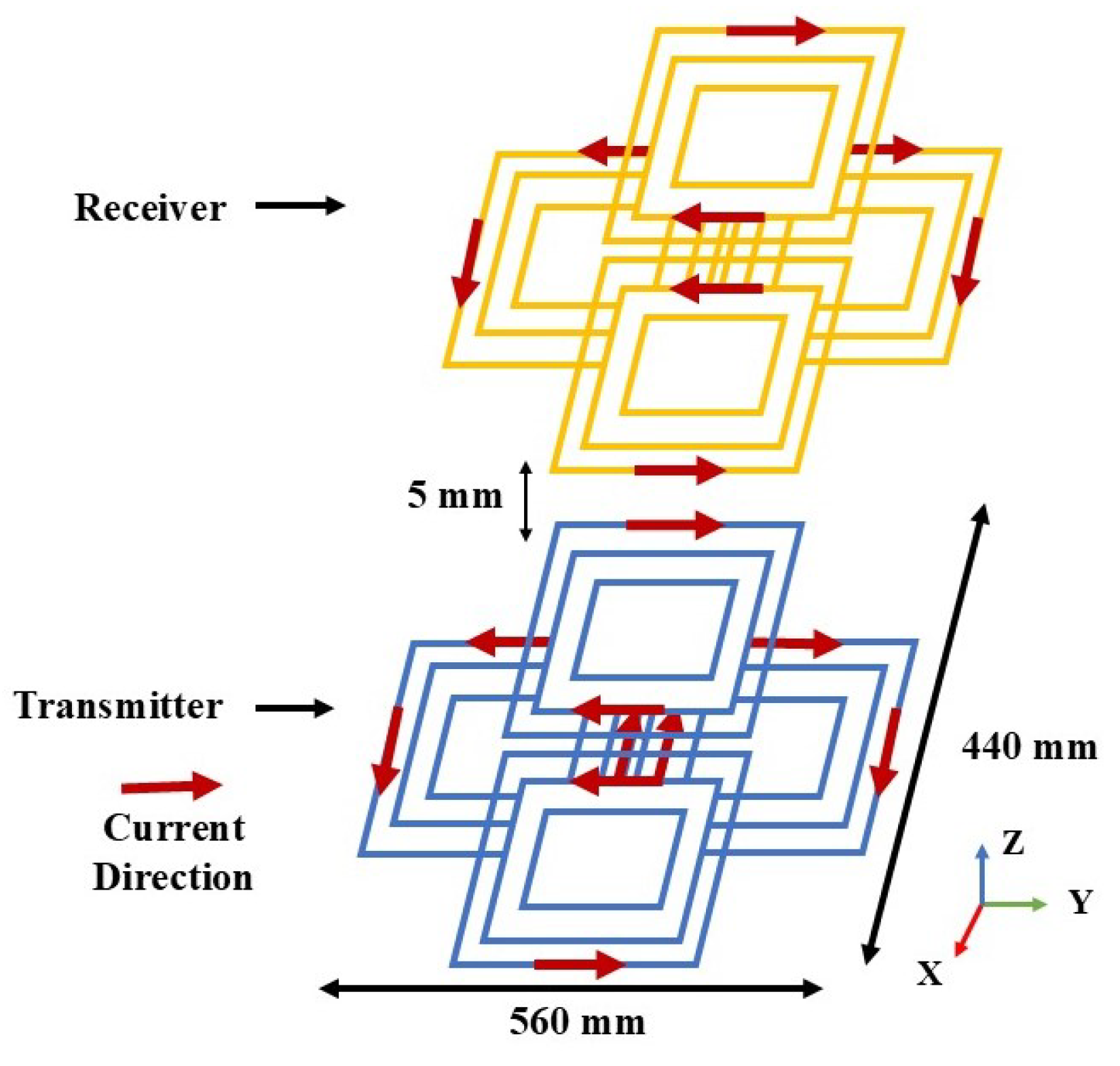
2.3. Symmetrical Cross Double-D Coupler

The SCDD coupler comprises of a configuration of four rectangular coils shown in Figure 3. To realize the configuration, it is important to begin with the fundamentals of electromagnetic induction between two current-carrying conductors and subsequently expand this concept to a rectangular current coil.

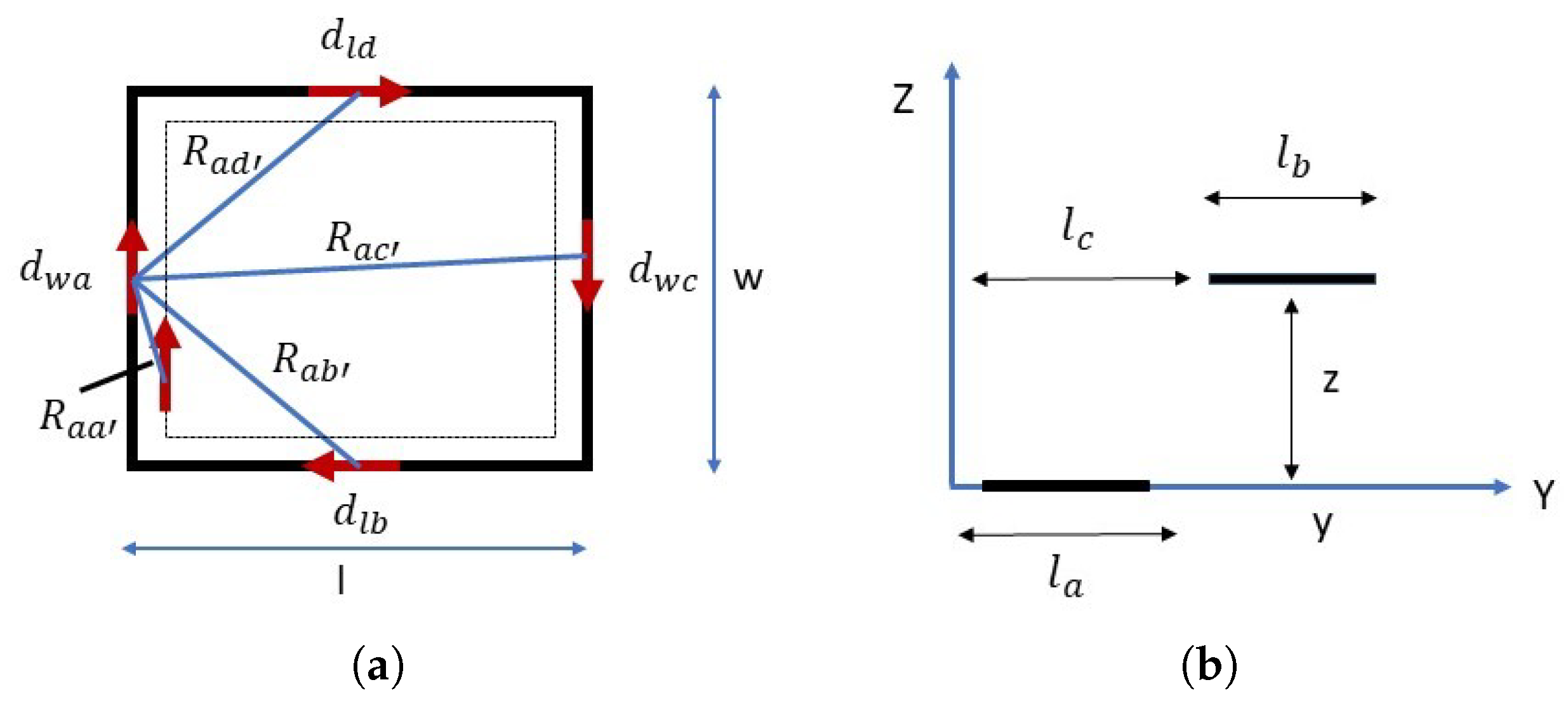
2.4. Self-Inductance Formulation

The inductance of a coil is defined as the ratio of the total magnetic flux to the current passing through the coil. The self-inductance ( L r c ) of a rectangular coil with N turns can be obtained with two sides from the symmetricity of rectangle as shown in Figure 4a. L l b and L w a denote the inductances along the length and width of the rectangular coil, as described in (1).
L r c = 2 L l b + 2 L w a
The self inductance of the coil having N number of turns can be expressed as (2), [21].
L N - r c = μ 0 4 π [ ( α 1 δ ) sinh 1 α 1 δ α 2 δ ( α 2 δ ) sinh 1 α 2 δ α 1 δ + ( α 1 δ ) sinh 1 α 1 δ r 0 + ( α 2 δ ) sinh 1 α 2 δ r 0 + r 0 sinh 1 r 0 α 1 δ + 2 ( α 1 δ ) 2 + ( α 2 δ ) 2 2 ( α 2 δ ) 2 + ( r 0 δ ) 2 2 ( α 1 δ ) 2 + r 0 2 2 r 0 ln ( 1 + 2 ) + 2 2 r 0 ]
The L r c for the rectangular coils with N number of turns is given as (3).
L N - rc = n = 1 N f ( l N , w N , g 0 , N )
where, α 1 = l N r 0 , α 2 = w N r 0 , δ = 2 ( N n i ) g 0 . r 0 and g 0 represent thickness of each turn and turn spacing, respectively.

2.5. Mutual Inductance Formulation

The configuration of wires upon which the derivation of mutual inductance between coils a and b is based is seen in Figure 4b. The symbols derived from the indices previously used to indicate the opposing sides in coil a will also be used to coil b. By utilizing the symmetry, the derivation is simplified to computation of the mutual inductance of exactly two sides of the rectangle.
The mutual inductance between the primary and secondary coils is affected by parameters such as the air gap. Figure 4b illustrates that the total mutual inductance between the transmitting and receiving pads that can be calculated by aggregating the mutual inductances of each pair of parallel current-carrying conductors within the pad configuration.
The mutual inductance of the two coils can be expressed as (4).
M a b = l c + l b l a l c l a l b l b + l c d l a d l b y 2 + z 2
The M a b of the two coils from (4) can be simplified as (5).
M a b = y ln y + y 2 + z 2 y 2 + z 2 | ( l b , l c + l b l a ) ( l b + l c , l c l a )
The mutual inductance is determined from a separate experimental set up of the coils. To determine mutual inductance from hardware, it is necessary to measure the inductance in two different configurations. The first measurement, referred to as L a i d i n g , is taken when the magnetic fields of both coils reinforce each other. The second measurement, known as L o p p o s i n g , is taken when the magnetic fields oppose each other. Using these two values, the mutual inductance (M) can be calculated with the expression as given in (6), [22].
M = L aiding L opposing 4
Table 1 presents the self-inductance of the SCDD coil obtained from both simulation and experimental measurements, along with mutual inductance values recorded under 40 mm and 80 mm coil misalignment conditions.
Considering ±5% accuracy in the instrument used for the experimental measurement of the inductances, there is a reasonably good agreement between simulated and measured values. This ensures correctness of the simulated magnetic field via FEA. At a 5 mm gap between transmitting and receiving coil with perfect coil alignment, the Double-D coil shows a magnetic flux leakage of 62.5%, while the SCDD coil lowers it to 42.4% of the total flux. This indicates a 20.1% reduction in leakage, leading to better coupling and higher efficiency.

2.6. Circuit Configuration

The schematic representation of IPT system is shown in Figure 5. The system architecture includes transmitter and the receiver. The transmitter side includes H-bridge inverter that converts the AC signal into DC voltage. The inverter output is sent to a series-series tuned compensation network, this network comprises an inductor (L) and a capacitor (C) linked in series on both the primary and secondary sides. The primary LC circuit is calibrated to the inverter’s operating frequency to optimize output power transfer efficiency, while the secondary LC circuit guarantees voltage amplification and load-independent current transmission.
The primary side compensation circuit has been extensively calibrated to attain resonance with the transmitter coil. The voltage at the receiving end has been rectified to a DC voltage using a full bridge uncontrolled rectifier. The inverter switches are represented by S 1 , S 2 , S 3 and S 4 operated at switching frequency of 85 kHz, and the rectifier diodes are denoted by D 1 , D 2 , D 3 , and D 4 .

2.7. System Modeling

The IPT system that includes a transmitting and a receiving end, is detailed in this section. The circuit system modeling of transformer is shown in Figure 6. This is a resonant LC network with two inductors L P and L S and two capacitors C P and C S , and a mutual inductance L M coupling the two inductors. I P and I S are the current flowing through transmitting and receiving coil respectively.
The system consists of LC compensation network that comprises of an inductor (L) and a capacitor (C) linked in series on both the primary and secondary sides. This compensation circuit cancels the secondary reactance by attaining resonance at the working frequency, ensuring that the power requirement of the receiver coil is entirely an active component, eliminating reactive components.
By ignoring the small internal resistance of the coils, the input voltage ( V i n ) and output voltage ( V o u t ) are given as follows by applying Kirchhoff’s Voltage Law (KVL) to the circuit given in Figure 6.
V i n = I P j ω C P + I P j ω ( L P L M ) + L M j ω ( I P I S )
V o u t = I S j ω C S + I S j ω ( L S L M ) + L M j ω ( I P I S )
At resonance, the capacitive reactance is equal to the inductive reactance, described as 1 j ω C P = j ω L P . Based on this relation, (7) and (8) can be written as V i n = j ω I S L M , and V o u t = j ω I P L M , respectively.
The output power ( P o u t ) is then calculated by using the following relationship:
P out = V out I S = ω L M I P I S

3. Results and Discussions

SCDD coil is simulated using FEA and have been validated in the experimental test bench set up.

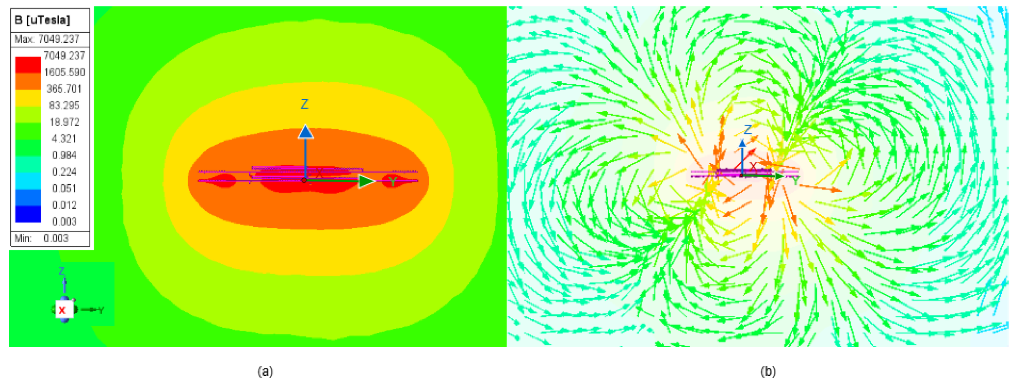
3.1. Simulation Results Based on FEA Analysis

Ansys Maxwell was used to simulate magnetic fields for three different coil configurations: Single-D, Double-D, and SCDD coils.

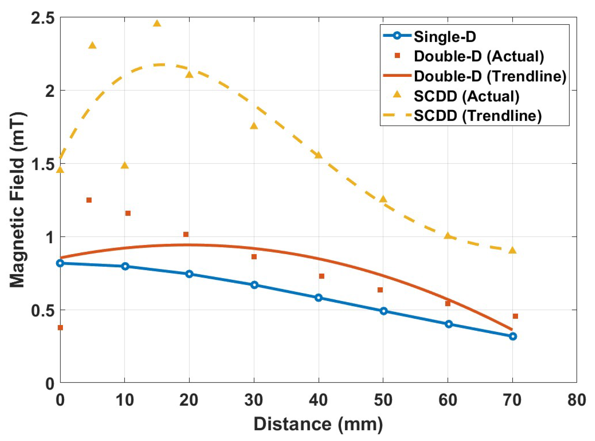
3.1.1. Calculation of the Magnetic Field for Single-D, Double-D and SCDD Along Z-Axis at the Center of the Coil

Finite element analysis was carried out for Single-D, Double-D, and SCDD coil configurations using ANSYS Electromagnetic Desktop for simulation and implementation. In wireless power transfer, calculation of the magnetic field is essential because it establishes the amount of voltage produced in the receiver coil and guarantees that the magnetic field stays within safe limits to prevent harmful exposure to humans. Additionally, the investigation showed a decreased stray field that remained below 15 μT at 800 mm from the pad center while conforming to ICNIRP limitations. For real-world uses, this demonstrates that the pad design is safe and efficient.
In every instance, the coils were positioned parallel to the X-Y plane and 5 mm apart along the Z-axis. Distribution of the magnetic field along the Z-axis was examined, and for every arrangement, the field patterns in the Y-Z plane were extracted. Figure 7 shows Symmetrical Cross Double-D results for magnetic field distribution along Z-axis. Based on the color gradient shown in Figure 7a, magnetic field strength has been estimated and identified the region where the receiver coil experiences effective coupling. Vector magnetic field representation on the SCDD coils is as shown in Figure 7b.
The magnetic field distribution along the Z-axis at the center point (X = 0, Y = 0) for Single-D, Double-D, and Symmetrical Cross Double-D coils has been presented together in a single plot, as shown in the Figure 8. The SCDD coil exhibits a field profile, that is not only higher than that for Double-D but also indicates a relative flat top compared to continuously sloping profiles for Double-D and Single-D. The profile is expected to ensure consistent coupling and efficient power transfer in the SCDD coils. As a result, even if the receiving coil shifts or misaligned, it can still remain within a strong field region, preserving efficient output power transfer.

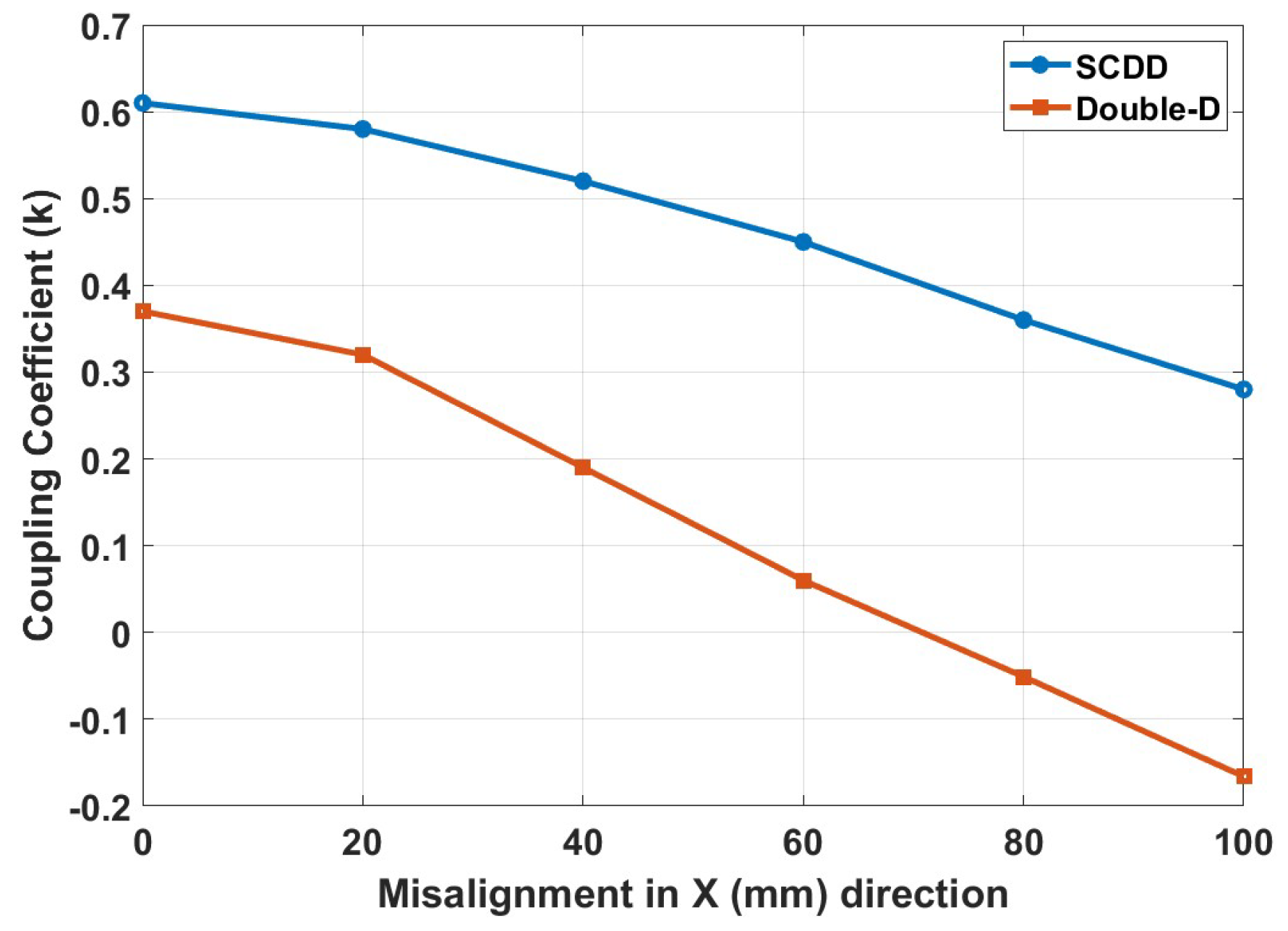
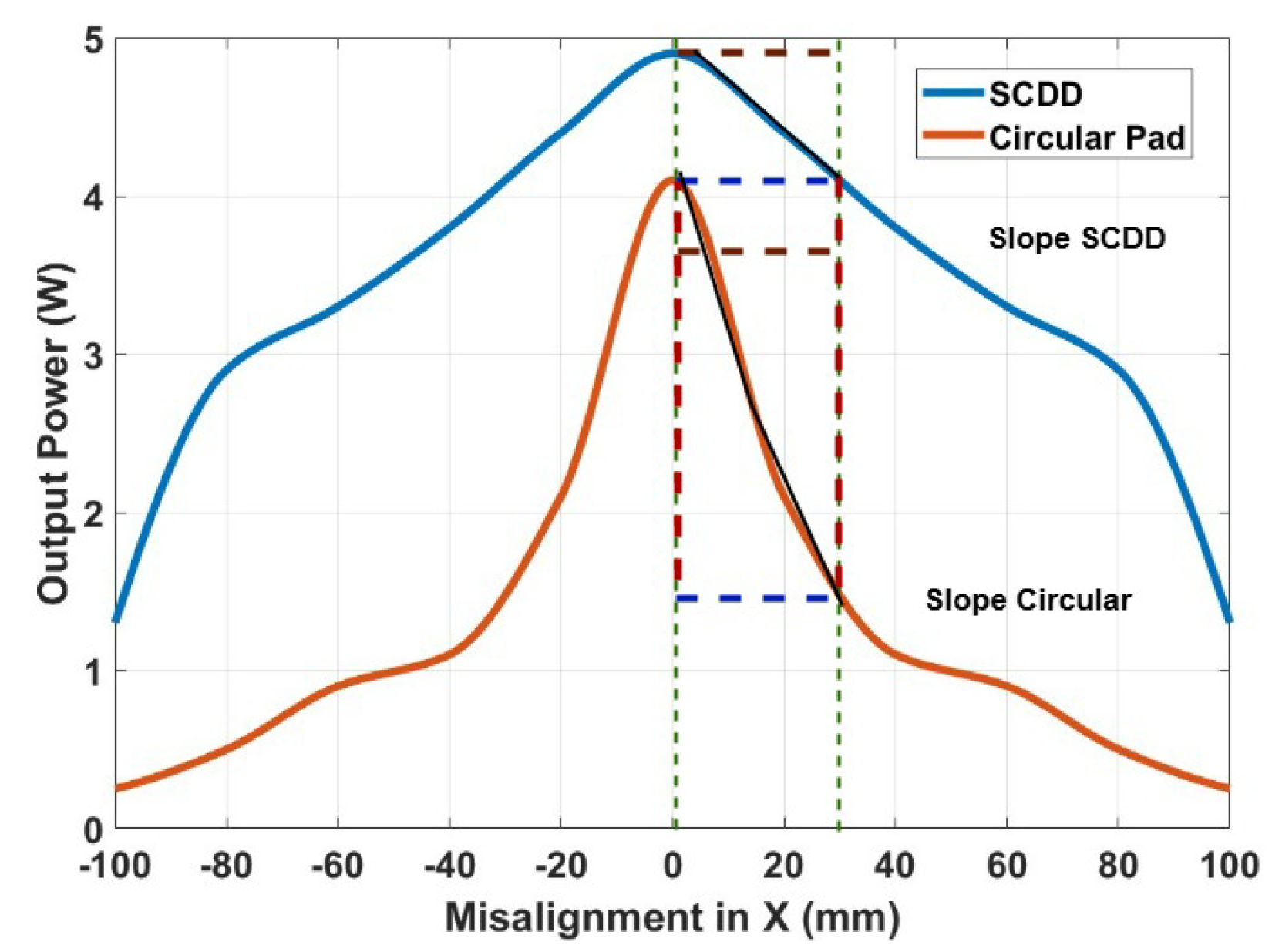
3.1.2. Coupling Coefficient of Double-D and Symmetrical Cross Double-D Coil During Misalignment

The receiving coils of both the DD and SCDD configurations were laterally misaligned along the X-axis by distances of 20 mm, 40 mm, 60 mm, and 100 mm. The coupling coefficient at each misalignment distance was obtained from ANSYS simulations, with the coils positioned 5 mm apart along the Z-axis. The coefficient of coupling, represented by ‘k’, measures the degree of magnetic interaction between two coils is expressed as:
k = M L 1 × L 2
The coefficient of coupling (k) is described as (11),
k 0 ; no magnetic linkage 1 ; ideal coupling
Based on the compensation network configuration and the operating conditions employed, the critical coupling coefficient ( k c ) was calculated as 0.73. The critical coupling coefficient ( k c ) can be expressed as follows: k c = Q 1 , where, Q = ω L s / R l .
The measured coupling coefficient (k) in the proposed topology remains below this threshold (k < k c ), indicating that the system operates within the stable region. As a result, bifurcation phenomena do not affect the power transfer process [23,24].
The plot illustrating the coupling coefficient corresponding to each misalignment distance is shown in Figure 9. As the misalignment increases, both coil types experience a drop in k due to diminished magnetic flux linkage [25]. However, the SCDD coil exhibits a slower and more stable decline, while the DD coil shows a sharp drop.
At 40 mm misalignment, the DD coil retains just 52% of its initial coupling, while the SCDD coil preserves around 82%, highlighting its superior tolerance to misalignment. This demonstrates the SCDD’s ability to sustain efficient coupling under misalignment. The improved performance of SCDD is largely due to its symmetrical and overlapping design, which supports a more uniform and robust magnetic field. Additionally, SCDD coils produces different coupling routes, thereby performing better under misalignment condition.

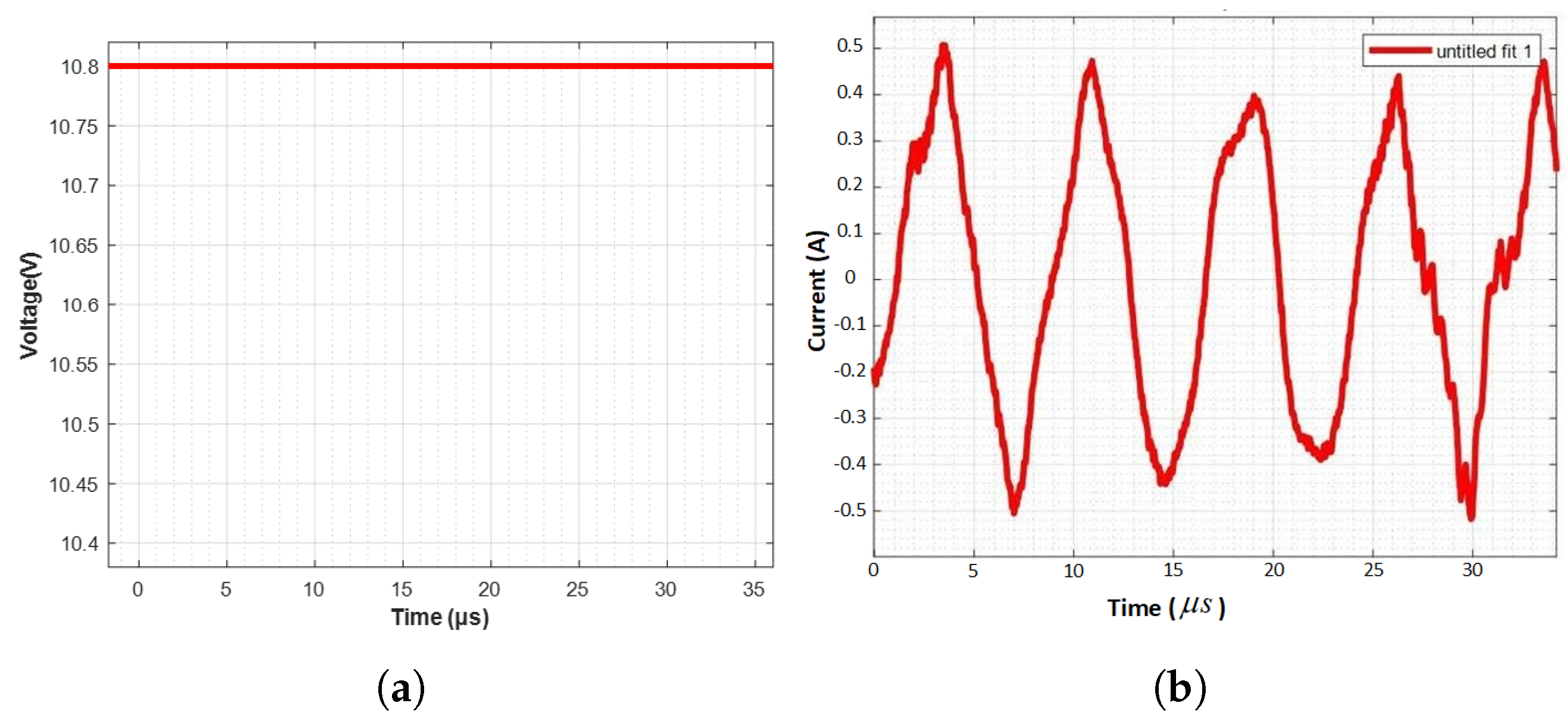
3.2. Experimental Results

Experiments were performed with SCDD and circular coils (diameter of 360 mm). Entire experimental set-up is shown in Figure 10a while a close-up of the SCDD coil is shown in Figure 10b. The design parameters are presented in Table 2.
The system was operated at 16 V DC input, frequency of 85 kHz, and an air-gap of 5 mm between the two SCDD coils. Input and output power was measured through voltage and current measurements at the respective locations. Lateral misalignment ranging from 0 to 100 mm were created to measure output power at different intervals. Figure 11a,b present the measured input voltage and current waveforms for the primary coil during the experiment. On the secondary side, Figure 12a,b show the output current and the voltage across a 100 Ω resistive load.
Figure 13a illustrates output power at different inputs indicating a progressive development in the nature of plots. Figure 13b shows simulated output power at different misalignment for Double-D, Circular, and SCDD coil structures, each implemented with 15 turns. At 40 mm misalignment, the DD coil retains only 47.8% of its peak aligned power, the circular coil retains 59.2%, while the SCDD coil maintains 86.3%, indicating superior misalignment tolerance of the SCDD topology. Figure 14 illustrates a comparison between experimentally measured and simulated values of output power at different misalignment conditions. The general nature of the two plots is very similar.
The difference in power values can be attributed to inaccuracies (±5%) in the equipment used for experiments, use of stranded wire, and somewhat ideal flux linkages in the FEA simulations. Figure 15 indicates a comparison between experimentally obtained values of output power at different misalignment condition for SCDD and circular couplers. Misalignment performance is quantified in terms of the slope (W/mm). The results indicate that the SCDD electromagnetic coupler offers approximately 2.5 times greater tolerance to misalignment compared to the circular coupler. Under a 40 mm misalignment, the SCDD coupler retains about 78% of the transferred power, whereas the circular coupler retains only 24% under the same conditions.
Table 3 present the power efficiency and overall system performance in aligned conditions. The comparison confirms the strength of the proposed model and supports its use in designing reliable and efficient wireless power transfer systems, proving its suitability for practical implementation. Additionally, the SCDD coupler achieved 15% higher power transfer than the standard circular coupler when tested in the aligned position.

4. Conclusions

This study analyzes the magnetic field distribution for Single-D, DD, and SCDD coil configurations under perfect alignment along the Z-axis, with a separation gap of 5 mm between the coils. The magnetic field strength has been observed for all these coils and it has been observed that the field strength are higher for SCDD. In addition to this, using ANSYS, the magnetic field density is found to be within the safety limits for currents up to 10A keep the stray field below 15 µT at 800 mm from the coupler’s center, meeting ICNIRP standards. The SCDD configuration exhibits a strong coefficient of coupling, which indicates effective and efficient transfer of output power. Output power was determined using both simulation and experimental setups, with simulated values higher than experimental and an efficiency of 88% at perfect alignment. The SCDD design has 15% more power transfer than the conventional circular pads under the same airgap. The SCDD electromagnetic coupler has 2.5 times better misalignment tolerance than the typical circular coupler. At 40 mm misalignment, the SCDD design retained 78% of the maximum power compared to only 24% of the maximum power, for the circular design. This demonstrates the effectiveness in maintaining performance despite misalignment, making it a promising solution for wireless charging applications. An optimization in the size of the side wings is recommended as a future work, so that cost of the copper can be reduced. Additionally, comparison of power density with a DD coil and optimization of transferred power through the SCDD coil are suggested as the future research work.

Author Contributions

A.R. implemented the ANSYS simulations, analyzed and validated results with experimental setup, and prepared the draft of the manuscript. S.M.M. supervised the overall project, provided technical guidance, and contributed to manuscript revision. T.O. assisted in hardware set-up and its validation. All authors have read and agreed to the published version of the manuscript.

Funding

This research was funded by Center for Energy Systems Research, Tennessee Tech University, USA.

Data Availability Statement

The original contributions are given in this manuscript. For additional queries, please contact to the corresponding author.

Conflicts of Interest

Author Taiye Owu was employed by the company Bonitron, Inc. The remaining authors declare that the research was conducted in the absence of any commercial or financial relationships that could be construed as a potential conflict of interest.

Abbreviations

The following abbreviations are used in this manuscript:
WPTWireless Power Transfer
EVElectric Vehicle
SCDDSymmetrical Cross Double-D
FEAFinite Element Analysis
IPTInductive Power Transfer
DDDouble-D
FOCFractional-Order Capacitor
DDCDouble-D Circular
SAESociety of Automotive Engineers
ICNIRPInternational Commission on Non-Ionizing Radiation Protection
PWMPulse Width Modulation

References

  1. López-Alcolea, F.J.; Vázquez del Real, J.; Roncero-Sánchez, P.; Parreño Torres, A. Modeling of a Magnetic Coupler Based on Single- and Double-Layered Rectangular Planar Coils With In-Plane Misalignment for Wireless Power Transfer. IEEE Trans. Power Electron. 2020, 35, 5102–5121. [Google Scholar] [CrossRef]
  2. Ramezani, A.; Narimani, M. Optimized Electric Vehicle Wireless Chargers With Reduced Output Voltage Sensitivity to Misalignment. IEEE J. Emerg. Sel. Top. Power Electron. 2020, 8, 3569–3581. [Google Scholar] [CrossRef]
  3. Bosshard, R.; Iruretagoyena, U.; Kolar, J.W. Comprehensive Evaluation of Rectangular and Double-D Coil Geometry for 50 kW/85 kHz IPT System. IEEE J. Emerg. Sel. Top. Power Electron. 2016, 4, 1406–1415. [Google Scholar] [CrossRef]
  4. Luo, Z.; Wei, X.; Pearce, M.G.S.; Covic, G.A. Multiobjective Optimization of Inductive Power Transfer Double-D Pads for Electric Vehicles. IEEE Trans. Power Electron. 2021, 36, 5135–5146. [Google Scholar] [CrossRef]
  5. Liu, C.; Jiang, C.; Qiu, C. Overview of Coil Designs for Wireless Charging of Electric Vehicle. In Proceedings of the 2017 IEEE PELS Workshop on Emerging Technologies: Wireless Power Transfer (WoW), Chongqing, China, 20–22 May 2017; pp. 1–6. [Google Scholar] [CrossRef]
  6. Mohammad, M.; Pries, J.; Onar, O.; Anwar, S.; Galigekere, V.P.; Su, G.-J.; Wilkins, J. Comparison of Leakage Magnetic Field from Matched and Mismatched Double-D Coil Based Wireless Charging System for Electric Vehicles. In Proceedings of the 2019 IEEE Energy Conversion Congress and Exposition (ECCE), Baltimore, MD, USA, 29 September–3 October 2019; pp. 5733–5739. [Google Scholar] [CrossRef]
  7. Barmada, S.; Musolino, A.; Zhu, J.; Yang, S. A Novel Coil Architecture for Interoperability and Tolerance to Misalignment in Electric Vehicle WPT. IEEE Trans. Magn. 2023, 59, 1–5. [Google Scholar] [CrossRef]
  8. Wang, Q.; Che, W.; Mongiardo, M.; Monti, G. Wireless Power Transfer System With High Misalignment Tolerance for Bio-Medical Implants. IEEE Trans. Circuits Syst. II Express Briefs 2020, 67, 3023–3027. [Google Scholar] [CrossRef]
  9. Feng, T.; Sun, Y.; Feng, Y.; Dai, X. A Tripolar Plane-Type Transmitter for Three-Dimensional Omnidirectional Wireless Power Transfer. IEEE Trans. Ind. Appl. 2022, 58, 1254–1267. [Google Scholar] [CrossRef]
  10. Wang, L.; Sun, P.; Liang, Y.; He, L.; Wu, X.; Deng, Q. Research on the Control Strategy of Communication-Free IPT System Based on Multiparameter Joint Real-Time Identification. IEEE Trans. Power Electron. 2024, 39, 1912–1926. [Google Scholar] [CrossRef]
  11. Yadav, P.; Veerachary, M. Modified Coupler With Reduced Misalignment Issues for Wireless Power Transfer System. IEEE Trans. Ind. Appl. 2024, 60, 5763–5777. [Google Scholar] [CrossRef]
  12. Shi, W.; Lan, H.; Li, D.; Guo, D.; Yin, H. Enhancing Simplified Control and Misalignment Tolerance in Autonomous Fractional-Order Wireless Power Transfer System with an Improved Primary-Side Control Strategy. IEEE J. Emerg. Sel. Top. Power Electron. 2025, in press. [Google Scholar] [CrossRef]
  13. Aurongjeb, M.; Liu, Y.; Ishfaq, M. Design and Simulation of Inductive Power Transfer Pad for Electric Vehicle Charging. Energies 2025, 18, 244. [Google Scholar] [CrossRef]
  14. Zhang, Y.; Chen, S.; Li, X.; Tang, Y. Design of High-Power Static Wireless Power Transfer via Magnetic Induction: An Overview. CPSS Trans. Power Electron. Appl. 2021, 6, 281–297. [Google Scholar] [CrossRef]
  15. Wang, X.; Leng, M.; Zhang, X.; Tian, Q.; He, L.; Ma, H. An Intermediate Coil for Misalignment Tolerant IPT System with Dual Decoupled Receivers. In Proceedings of the IECON 2023—49th Annual Conference of the IEEE Industrial Electronics Society, Singapore, 16–19 October 2023; pp. 1–5. [Google Scholar] [CrossRef]
  16. Li, S.; Mi, C.C. Wireless Power Transfer for Electric Vehicle Applications. IEEE J. Emerg. Sel. Top. Power Electron. 2015, 3, 4–17. [Google Scholar] [CrossRef]
  17. Song, K.; Lee, C.; Kim, H.; Shin, J.; Jung, H. Design of DD Coil With High Misalignment Tolerance and Low EMF Emissions for Wireless Electric Vehicle Charging Systems. IEEE Trans. Power Electron. 2020, 35, 9034–9045. [Google Scholar] [CrossRef]
  18. Chu, C.-Y.; Lee, Y.-C.; Wu, C.-L.; Lin, Y.-C.; Kuo, Y.-C. Wireless Power Transfer System Design for Electric Vehicle Charging Considering A Wide Range of Coupling Coefficient Variation Depending on the Coil Misalignment. In Proceedings of the 2021 24th International Conference on Electrical Machines and Systems (ICEMS), Gyeongju, Republic of Korea, 31 October–3 November 2021; IEEE: New York, NY, USA, 2021; pp. 732–737. [Google Scholar]
  19. Lv, X.; Tang, X.; Cheng, K.; Chau, K.T. A cross double-D coil for electric vehicles dynamic wireless transfer system to reduce output power pulsation. In Proceedings of the 2020 8th International Conference on Power Electronics Systems and Applications (PESA), Hong Kong, China, 12–14 December 2020; IEEE: Piscataway, NJ, USA, 2020; pp. 1–6. [Google Scholar]
  20. Xiang, L.; Mi, C.; Zhang, M.; Zhao, Z.; Tang, X. A crossed DD geometry and its double-coil excitation method for electric vehicle dynamic wireless charging systems. IEEE Access 2018, 6, 45120–45128. [Google Scholar] [CrossRef]
  21. Owu, T. A Cross-Double D Coupler for Improved Tolerance to Misalignment Conditions. In Proceedings of the 2024 56th North American Power Symposium (NAPS), San Diego, CA, USA, 8–10 April 2024; pp. 1–6. [Google Scholar] [CrossRef]
  22. Guru, B.S.; Hiziroglu, H.R. Electric Machinery and Transformers, 3rd ed.; The Oxford Series in Electrical and Computer Engineering; Oxford University Press: New York, NY, USA, 2001. [Google Scholar]
  23. Bentalhik, I.; Lassioui, A.; El Fadil, H.; Bouanou, T.; Rachid, A.; El Idrissi, Z.; Hamed, A.M. Analysis, Design and Realization of a Wireless Power Transfer Charger for Electric Vehicles: Theoretical Approach and Experimental Results. World Electr. Veh. J. 2022, 13, 121. [Google Scholar] [CrossRef]
  24. Simonazzi, M.; Campanini, A.; Sandrolini, L.; Rossi, C. Design Procedure Based on Maximum Efficiency for Wireless Power Transfer Battery Chargers with Lightweight Vehicle Assembly. Energies 2022, 15, 70. [Google Scholar] [CrossRef]
  25. Owu, T.G. Modelling and Optimization of a Cross Double-D Electromagnetic Coupler for Enhanced Misalignment Performance in Wireless Charging Applications. Master’s Thesis, Tennessee Technological University, Cookeville, TN, USA, 2024. [Google Scholar]
Figure 1. Longitudinal and Lateral Misalignment View for EV.
Wevj 16 00405 g001
Figure 2. Representation of the current flow in the coils of WPT system. (a) Single-D implementation; (b) Double-D implementation.
Wevj 16 00405 g002
Figure 3. Representation of the current flow in the Symmetrical Cross Double-D coils of WPT system.
Wevj 16 00405 g003
Figure 4. Geometrical representation of conductor. (a) Rectangular coil for self-inductance; (b) Parallel conductor for Mutual inductance.
Wevj 16 00405 g004
Figure 5. IPT Circuit configuration.
Wevj 16 00405 g005
Figure 6. Equivalent Circuit configuration.
Wevj 16 00405 g006
Figure 7. Magnetic field along Z-axis for perfectly aligned SCDD coils in Y-Z plane when X = 0 and Y = 0: (a) Distribution of magnetic field (b) Vector magnetic field.
Wevj 16 00405 g007
Figure 8. Plot comparing magnetic field distribution along Z-axis at the center of perfectly aligned coils when X = 0 and Y = 0.
Wevj 16 00405 g008
Figure 9. Plot of coefficient of coupling for Double-D and SCDD at different misalignment distances (mm).
Wevj 16 00405 g009
Figure 10. Implementation of hardware for SCDD coil. (a) Experimental setup with inverter and rectifier circuit; (b) Bottom/Top view of the transmitting coil.
Wevj 16 00405 g010
Figure 11. Input Voltage and current at transmitting side. (a) Input voltage to the transmitter; (b) Transmitter side current.
Wevj 16 00405 g011
Figure 12. Output voltage and current of the load; (a) Output load voltage; (b) Output load current.
Wevj 16 00405 g012
Figure 13. Plots of P 0 vs. misalignment: (a) Experimental plots at different misalignment and V in ; (b) Simulated P 0 curves at different misalignment for SCDD, Circular and Double-D coil.
Wevj 16 00405 g013
Figure 14. Simulated and experimental output power for SCDD at different misalignment.
Wevj 16 00405 g014
Figure 15. Plots of output power for SCDD and circular pad at different misalignment.
Wevj 16 00405 g015
Table 1. Simulation and Experimental Results Comparison.
ParametersSimulationExperiment
Self-inductance (μH)241.53253.2
Mutual-inductance (μH) (Perfectly aligned)138.21151.5
Mutual-inductance (μH) (40 mm misaligned)118.36128
Mutual-inductance (μH) (80 mm misaligned)82.4974.5
Table 2. Design Parameters.
ParameterValue
Primary Coil Inductance L P (μH)253.2
Secondary Coil Inductance L S (μH)253.2
Primary Series Capacitance C P (nF)13.8
Secondary Series Capacitance C S (nF)13.8
Mutual Inductance (Perfectly aligned) (μH)151.5
Primary Coil Voltage V i n (V)16
Table 3. System performance at no misalignment.
System P in (W) P 0 (W) η (%)
Inverter7.25.678
SCDD5.64.988
Overall68
Disclaimer/Publisher’s Note: The statements, opinions and data contained in all publications are solely those of the individual author(s) and contributor(s) and not of MDPI and/or the editor(s). MDPI and/or the editor(s) disclaim responsibility for any injury to people or property resulting from any ideas, methods, instructions or products referred to in the content.

