
Driving-Cycle-Adaptive Energy Management Strategy for Hybrid Energy Storage Electric Vehicles

Abstract
1. Introduction
2. Vehicle Parameters and Model Construction
2.1. Key Parameters and Structure of Composite Energy Storage System
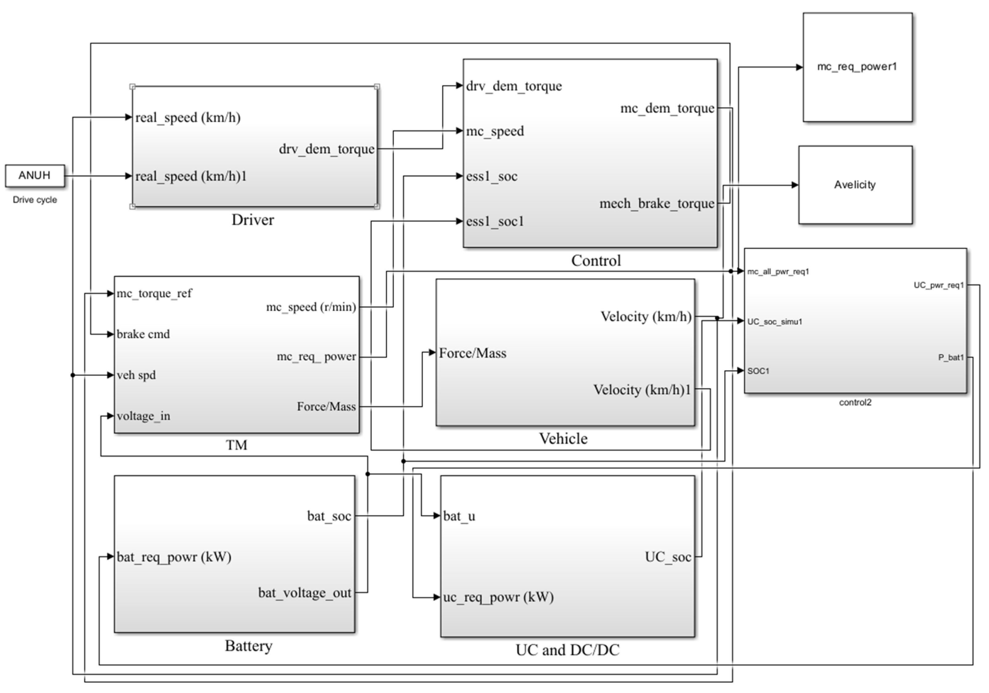
2.2. Simulation Model of Composite Energy Storage Vehicle
3. Optimization of Energy Management Strategy
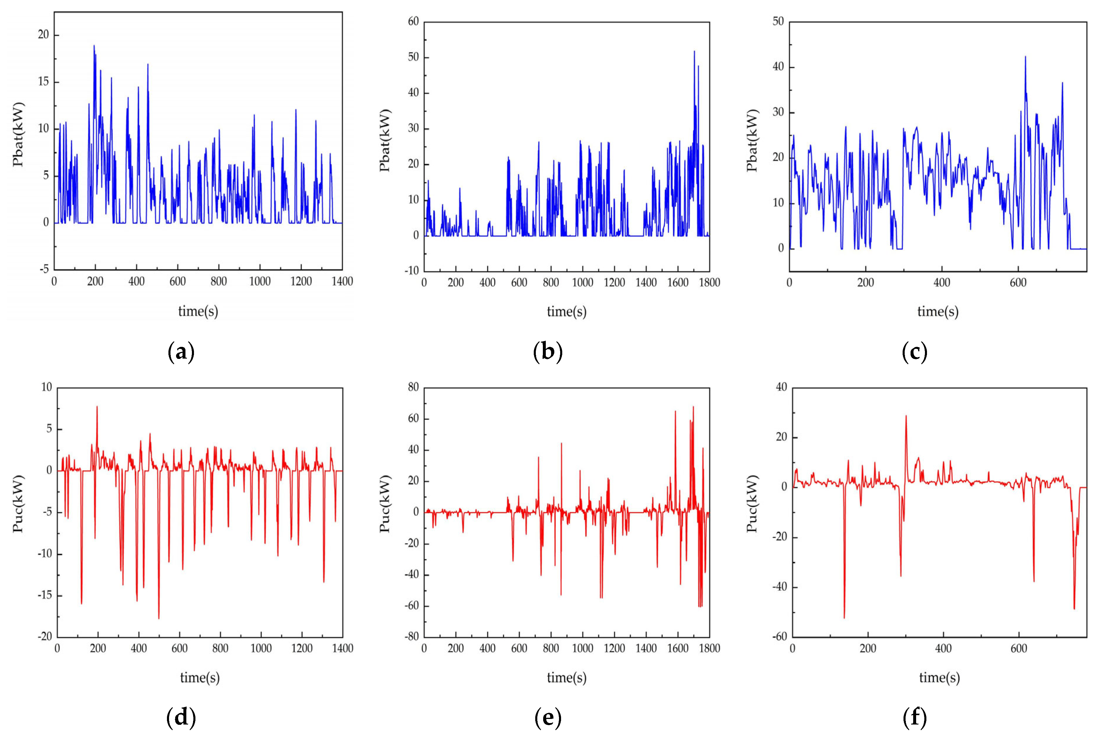
3.1. Modeling of Global Optimal Power Allocation Strategy
3.2. Improved Rule Control Strategy Based on Dynamic Programming
4. Construction of OCR Model
4.1. Feature Parameter Selection and Sample Partitioning
4.2. LS-SVM Model
4.3. Optimization of LS-SVM Modeling Based on GWO
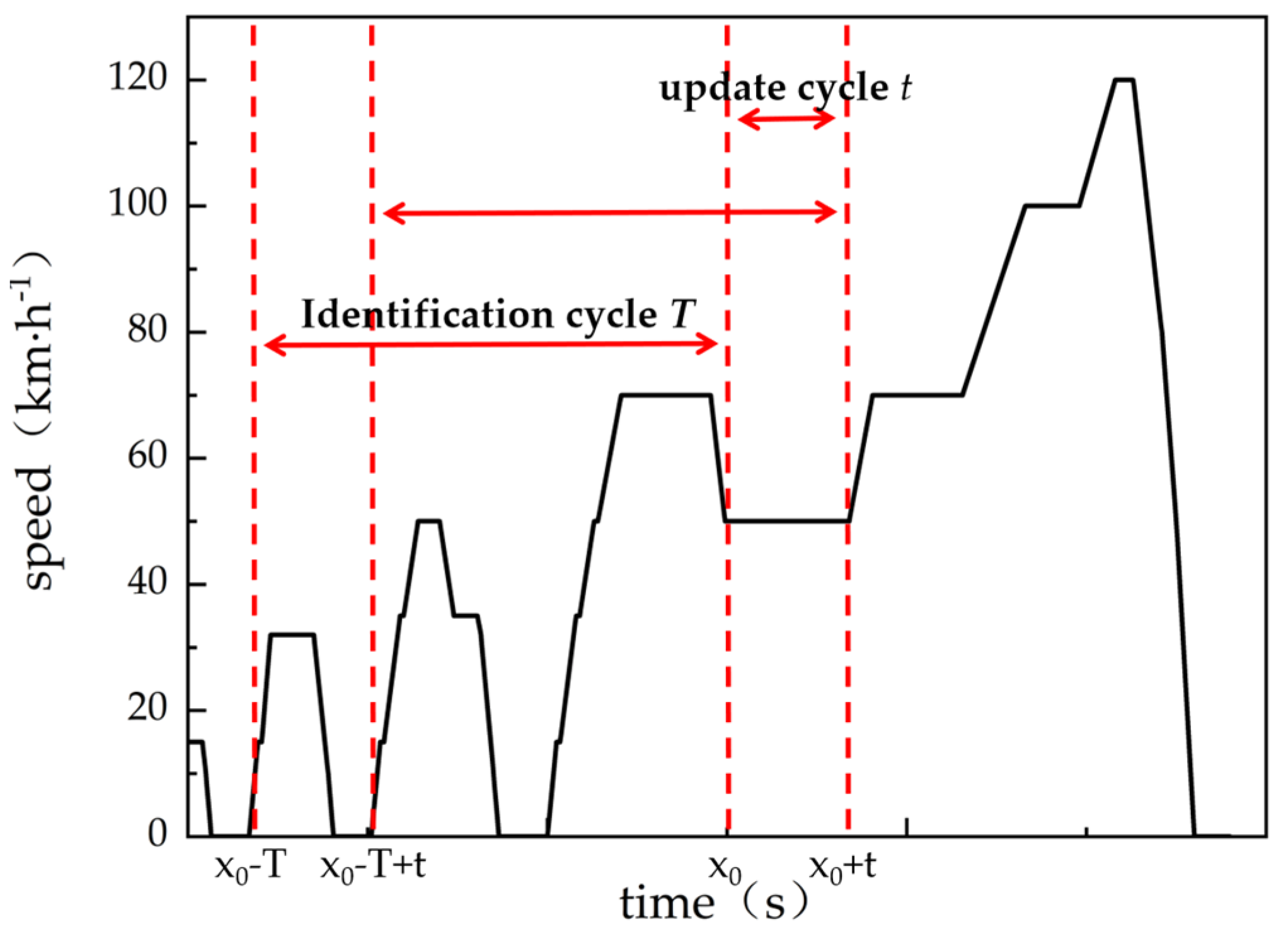
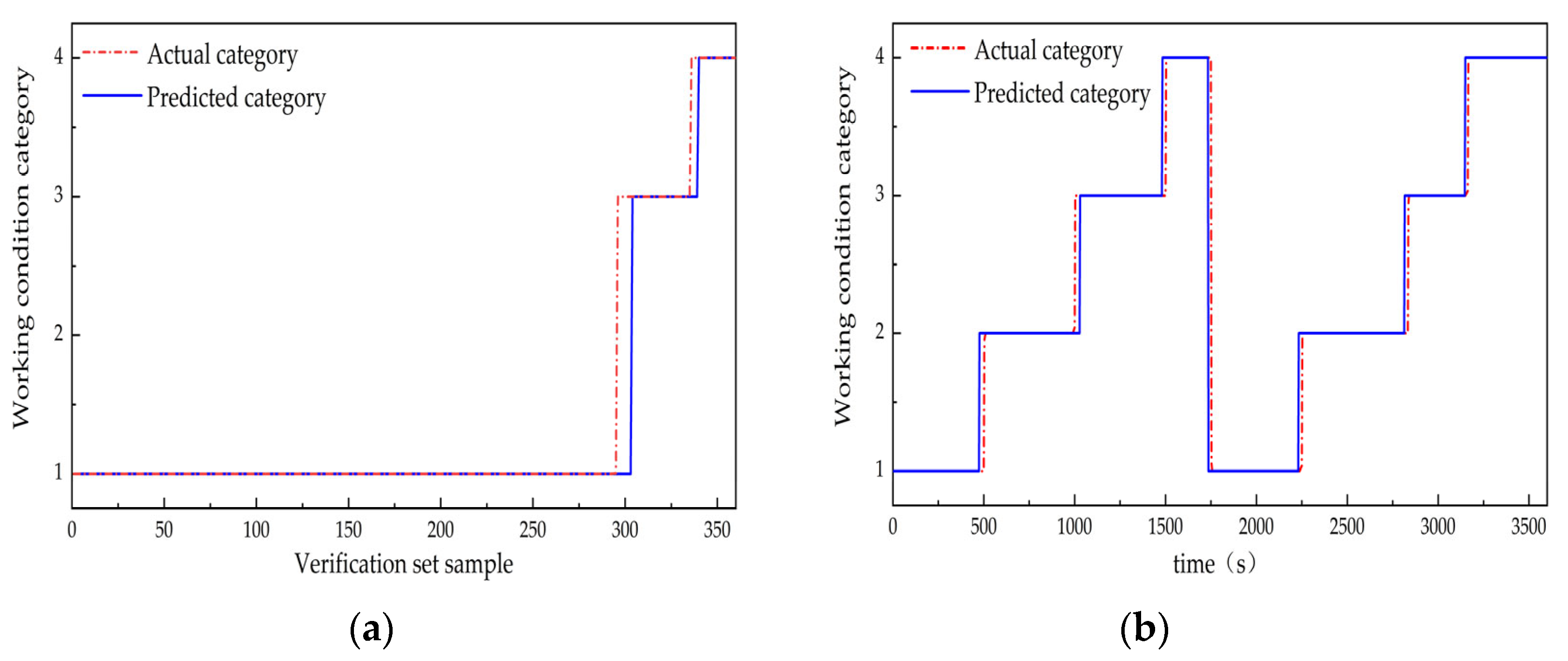
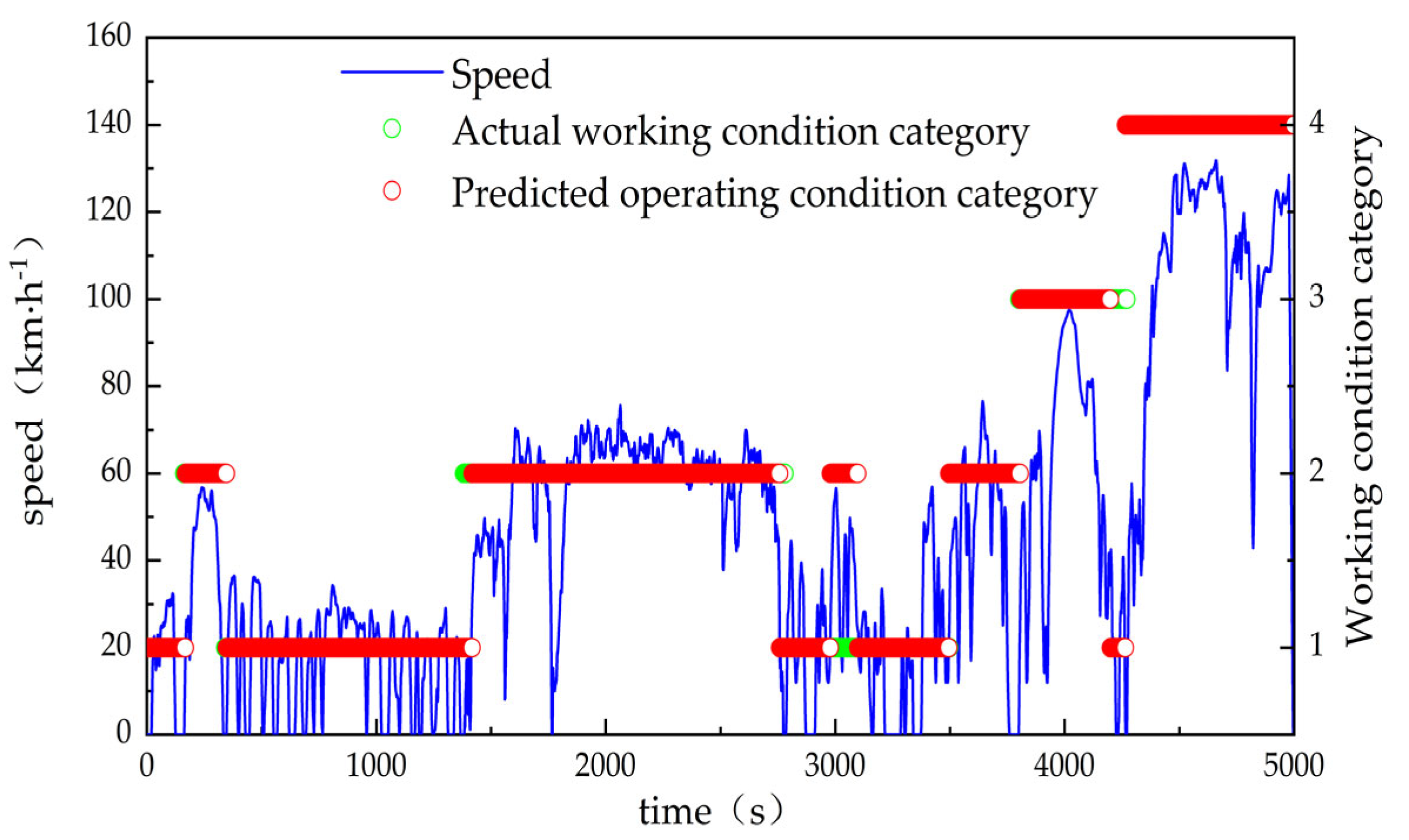
4.4. GWO-LSSVM Online Recognition of Working Conditions
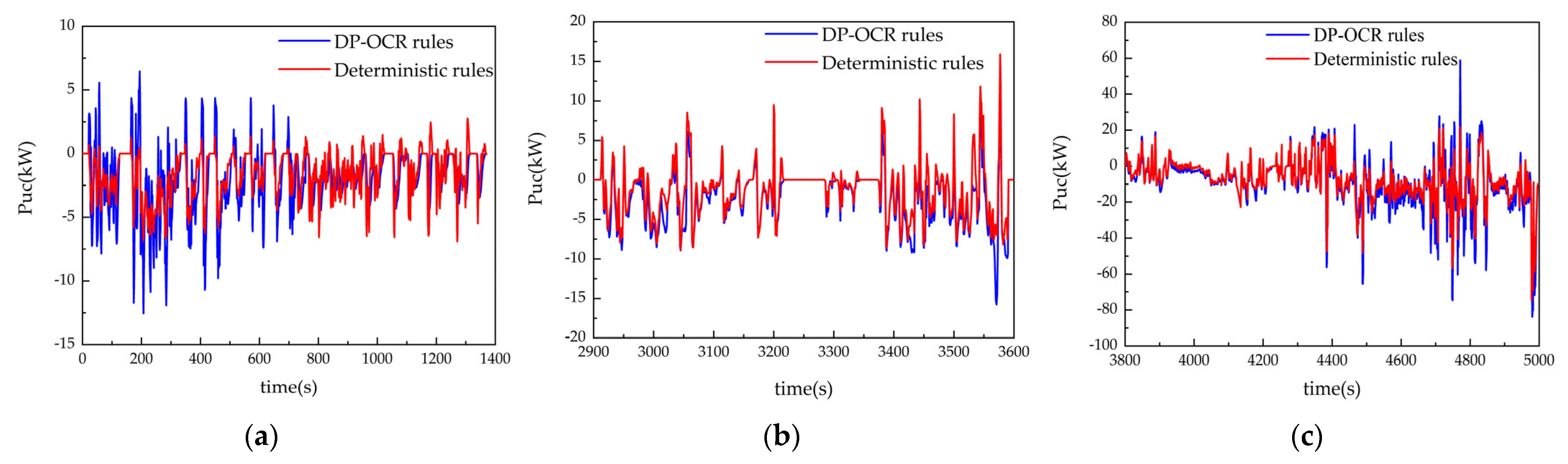
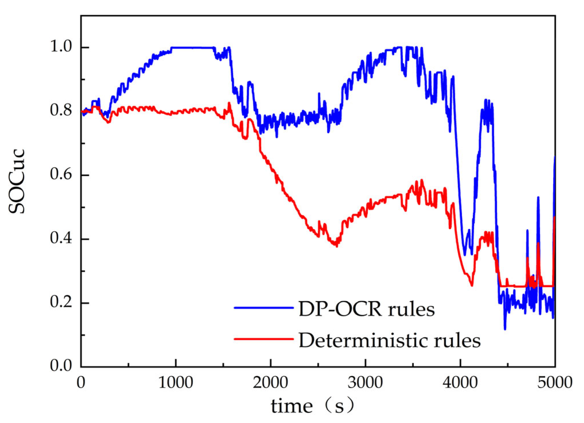
5. Simulation Analysis
6. Discussion
Author Contributions
Funding
Institutional Review Board Statement
Informed Consent Statement
Data Availability Statement
Conflicts of Interest
References
- Martínez-Gómez, J.; Espinoza, V.S. Challenges and Opportunities for Electric Vehicle Charging Stations in Latin America. World Electr. Veh. J. 2024, 15, 583. [Google Scholar] [CrossRef]
- Li, Y.; Luo, L.; Zhang, C. State of health assessment for lithium-ion batteries using incremental energy analysis and bidirectional long short-term memory. World Electr. Veh. J. 2023, 14, 188. [Google Scholar] [CrossRef]
- Kim, J.; Jaumotte, F.; Panton, A.J. Energy security and the green transition. Energy Policy 2025, 198, 114409. [Google Scholar] [CrossRef]
- Vanlalchhuanawmi, C.; Deb, S.; Onen, A. Energy management strategies in distribution system integrating electric vehicle and battery energy storage system: A review. Energy Storage 2024, 6, e682. [Google Scholar] [CrossRef]
- Urooj, A.; Nasir, A. Review of hybrid energy storage systems for hybrid electric vehicles. World Electr. Veh. J. 2024, 15, 342. [Google Scholar] [CrossRef]
- Hu, C.; Geng, M.; Yang, H. A Review of Capacity Fade Mechanism and Promotion Strategies for Lithium Iron Phosphate Batteries. Coatings 2024, 14, 832. [Google Scholar] [CrossRef]
- Kumaresan, N.; Rammohan, A. A comprehensive review on energy management strategies of hybrid energy storage systems for electric vehicles. J. Braz. Soc. Mech. Sci. Eng. 2024, 46, 146. [Google Scholar] [CrossRef]
- Zhang, F.; Wang, L.; Coskun, S. Energy management strategies for hybrid electric vehicles: Review, classification, comparison, and outlook. Energies 2020, 13, 3352. [Google Scholar] [CrossRef]
- Wang, Y.; Sun, Z.; Chen, Z. Development of energy management system based on a rule-based power distribution strategy for hybrid power sources. Energy 2019, 175, 1055–1066. [Google Scholar] [CrossRef]
- Rehman, U.U. Proximal Policy Optimization—Driven Real-Time Home Energy Management System with Storage and Renewables. Process Integr. Optim. Sustain. 2025, 9, 507–536. [Google Scholar] [CrossRef]
- Chen, X.; Li, M.; Chen, Z. Meta rule-based energy management strategy for battery/supercapacitor hybrid electric vehicles. Energy 2023, 285, 129365. [Google Scholar] [CrossRef]
- Tavakol-Sisakht, S.; Barakati, S.M. Energy manegement using fuzzy controller for hybrid electrical vehicles. J. Intell. Fuzzy Syst. 2016, 30, 1411–1420. [Google Scholar] [CrossRef]
- Van Jaarsveld, M.J.; Gouws, R. An active hybrid energy storage system utilising a fuzzy logic rule-based control strategy. World Electr. Veh. J. 2020, 11, 34. [Google Scholar] [CrossRef]
- Veerendra, A.S.; Mohamed, M.R.B.; García Márquez, F.P. Energy management control strategies for energy storage systems of hybrid electric vehicle: A review. Energy Storage 2024, 6, e573. [Google Scholar] [CrossRef]
- Xu, H.; Shen, M. The control of lithium-ion batteries and supercapacitors in hybrid energy storage systems for electric vehicles: A review. Int. J. Energy Res. 2021, 45, 20524. [Google Scholar] [CrossRef]
- Yi, F.; Lu, D.; Wang, X. Energy management strategy for hybrid energy storage electric vehicles based on pontryagin’s minimum principle considering battery degradation. Sustainability 2022, 14, 1214. [Google Scholar] [CrossRef]
- Liu, C.; Wang, Y.; Wang, L. Load-adaptive real-time energy management strategy for battery/ultracapacitor hybrid energy storage system using dynamic programming optimization. J. Power Sources 2019, 438, 227024. [Google Scholar] [CrossRef]
- Salkuti, S.R. Advanced technologies for energy storage and electric vehicles. Energies 2023, 16, 2312. [Google Scholar] [CrossRef]
- Yadlapalli, R.T.; Alla, R.K.R.; Kandipati, R. Super capacitors for energy storage: Progress, applications and challenges. J. Energy Storage 2022, 49, 104194. [Google Scholar] [CrossRef]
- Lemian, D.; Bode, F. Battery-supercapacitor energy storage systems for electrical vehicles: A review. Energies 2022, 15, 5683. [Google Scholar] [CrossRef]
- Shi, D.; Xu, H.; Wang, S. Deep reinforcement learning based adaptive energy management for plug-in hybrid electric vehicle with double deep Q-network. Energy 2024, 305, 132402. [Google Scholar] [CrossRef]
- Liu, C.; Liu, Y. Energy management strategy for plug-in hybrid electric vehicles based on driving condition recognition: A review. Electronics 2022, 11, 342. [Google Scholar] [CrossRef]
- Zhang, Q.; Fu, X. A neural network fuzzy energy management strategy for hybrid electric vehicles based on driving cycle recognition. Appl. Sci. 2020, 10, 696. [Google Scholar] [CrossRef]
- Wang, Y.; Zhang, Y.; Zhang, C. Genetic algorithm-based fuzzy optimization of energy management strategy for fuel cell vehicles considering driving cycles recognition. Energy 2023, 263, 126112. [Google Scholar] [CrossRef]
- Li, F.; Wang, X.; Bao, X. Energy Management Strategy for Fuel Cell Vehicles Based on Online Driving Condition Recognition Using Dual-Model Predictive Control. Sensors 2024, 24, 7647. [Google Scholar] [CrossRef]
- Ma, Y.; Tian, S. Research on driving condition recognition in hybrid electric vehicle energy management strategy. J. Phys. Conf. Ser. 2024, 2782, 012083. [Google Scholar] [CrossRef]
- Pan, C.; Tao, Y.; Liu, Q. Grey wolf fuzzy optimal energy management for electric vehicles based on driving condition prediction. J. Energy Storage 2021, 44, 103398. [Google Scholar] [CrossRef]
- Zhou, X.; Zhang, R.; Wang, Y. Electrochemical Impedance Spectroscopy-Based Dynamic Modeling of Lithium-Ion Batteries Using a Simple Equivalent Circuit Model. Energy Technol. 2023, 11, 2300473. [Google Scholar] [CrossRef]
- Ma, M.; Xu, E.; Zheng, W. The optimized real-time energy management strategy for fuel-cell hybrid trucks through dynamic programming. Int. J. Hydrogen Energy 2024, 59, 10–21. [Google Scholar] [CrossRef]
- Xiong, R.; He, H.; Sun, F. Methodology for optimal sizing of hybrid power system usingparticle swarm optimization and dynamic programming. Energy Procedia 2015, 75, 1895–1900. [Google Scholar] [CrossRef]
- Pinto, C.; Barreras, J.V.; Castro, R. Study on the combined influence of battery models and sizing strategy for hybrid and battery-based electric vehicles. Energy 2017, 137, 272–284. [Google Scholar] [CrossRef]
- Wang, J.; Liu, P.; Hicks-Garner, J. Cycle-life model for graphite-LiFePO4 cells. J. Power Sources 2011, 196, 3942–3948. [Google Scholar] [CrossRef]
- Silva, S.F.; Eckert, J.J.; Silva, F.L. Multi-objective optimization design and control of plug-in hybrid electric vehicle powertrain for minimization of energy consumption, exhaust emissions and battery degradation. Energy Convers. Manag. 2021, 234, 113909. [Google Scholar] [CrossRef]
- Leong, W.C.; Bahadori, A.; Zhang, J. Prediction of water quality index (WQI) using support vector machine (SVM) and least square-support vector machine (LS-SVM). Int. J. River Basin Manag. 2021, 19, 149–156. [Google Scholar] [CrossRef]
- Song, Z.; Hou, J.; Xu, S. The influence of driving cycle characteristics on the integrated optimization of hybrid energy storage system for electric city buses. Energy 2017, 135, 91–100. [Google Scholar] [CrossRef]
- Aatif, J.; Bhawna, M.; Rajendra, B.K. Grey wolf optimization (GWO) with the convolution neural network (CNN)-based pattern recognition system. Imaging Sci. J. 2022, 70, 238–252. [Google Scholar]


| Key Components | Comments | Value |
|---|---|---|
| Vehicle | curb weight/kg | 1860 |
| full load mass/kg | 2290 | |
| mechanical efficiency | 0.94 | |
| main reduction ratio | 8.5 | |
| wheel radius/m | 0.3 | |
| windward area/m2 | 2.402 | |
| wind resistance coefficient | 0.3 | |
| rolling resistance coefficient | 0.015 | |
| rotational mass conversion coefficient | 1.05 | |
| Drive motor | rated speed/r·min−1 | 3500 |
| peak speed/r·min−1 | 9300 | |
| rated power/kW | 40 | |
| peak power/kW | 115 | |
| rated torque/N∙m | 110 | |
| peak torque/N∙m | 270 | |
| Lithium battery | battery pack rated voltage/V | 340 |
| battery pack rated current//A | 230 | |
| battery pack peak current/A | 460 | |
| lithium battery pack capacity/Ah | 360 | |
| lithium battery pack energy/kWh | 111 | |
| Supercapacitor | rated voltage of supercapacitor group/V | 330 |
| supercapacitor group capacity/F | 3 × 10⁵ | |
| supercapacitor group energy/kWh | 0.375 |
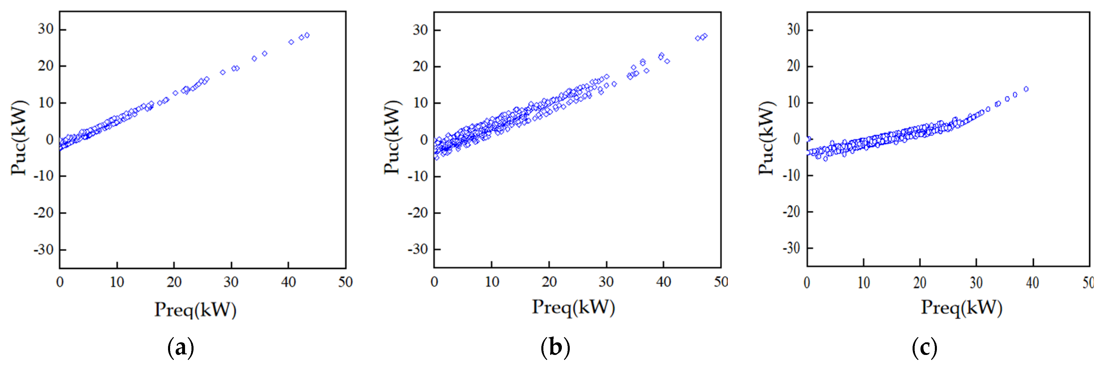
| Drive Cycle | Fitting Curve | Coefficient of Determination R2 |
|---|---|---|
| UDDS | f(x) = 0.6295x − 0.568 | 0.9981 |
| CLTC-P | f(x) = 0.6472x − 2.107 | 0.9875 |
| HWFET | x < 27.28, f(x) = 0.2873x − 3.912 | 0.9928 |
| x ≥ 27.28, f(x) = 0.8394x − 18.69 | 0.9964 |
| Running State | Switching Conditions | Power Allocation |
|---|---|---|
| Supercapacitors and batteries jointly provide driving power | High power demand SOCuc > 0.25 | Puc = aPreq + b Pbat = Preq − Puc |
| The battery provides all the driving power | High power demand SOCuc ≤ 0.25 | Pbat = Preq |
| The battery provides all the driving power | Low power demand 0.25 ≤ SOCuc ≤ 0.95 | Pbat = Preq |
| Supercapacitors fully recover braking energy | 0 ≤ SOCuc < 0.95 | Puc = Preq Pbat = 0 |
| Supercapacitors and batteries do not recover braking energy | 0.95 ≤ SOCuc | Puc = 0 Pbat = 0 |
| Serial Number | Characteristic Parameter | Meaning |
|---|---|---|
| 1 | vmax (km/h) | maximum speed |
| 2 | vave (km/h) | average speed |
| 3 | aave (m/s2) | average acceleration |
| 4 | ade_ave (m/s2) | average deceleration |
| 5 | run (%) | uniform ratio |
| 6 | racc (%) | acceleration ratio |
| 7 | rdec (%) | deceleration ratio |
| Energy Management Strategy | Determine Rules | DP-OCR Rules | Optimization Degree (%) |
|---|---|---|---|
| Peak power of battery (kW) | 47.73 | 40.41 | 15.37 |
| Peak current of battery (A) | 119.32 | 101.13 | 15.37 |
| Reduction in battery SOC | 20.86 | 19.19 | 8 |
| Temperature rise of battery (°C) | 1.41 | 0.94 | 33.3 |
| Vehicle and Energy Management Strategy | Energy Consumption of Lithium Batteries (kWh) | Energy Consumption of Supercapacitors (kWh) | Vehicle Energy Consumption (kWh) | Optimization Degree (%) |
|---|---|---|---|---|
| Single battery | 25.8852 | - | 25.8852 | - |
| Determine rules | 23.1546 | 0.1365 | 23.2911 | 10.02 |
| DP-OCR rules | 21.3009 | 0.0586 | 21.3595 | 17.48 |
| Vehicle and Energy Management Strategy | Single Condition Battery Capacity Attenuation (%) | 10,000 Kilometers Battery Capacity Degradation (%) | 30,000 Kilometers Battery Capacity Degradation (%) | 50,000 Kilometers Battery Capacity Degradation (%) | Optimization Degree of Battery Attenuation for 50,000 Kilometers (%) |
|---|---|---|---|---|---|
| Single battery | 0.009225 | 1.8409 | 3.3699 | 4.4119 | - |
| Determine rules | 0.007636 | 1.5244 | 2.7894 | 3.6534 | 17.19 |
| DP-OCR rules | 0.007209 | 1.4391 | 2.6331 | 3.4487 | 21.83 |
Disclaimer/Publisher’s Note: The statements, opinions and data contained in all publications are solely those of the individual author(s) and contributor(s) and not of MDPI and/or the editor(s). MDPI and/or the editor(s) disclaim responsibility for any injury to people or property resulting from any ideas, methods, instructions or products referred to in the content. |
© 2025 by the authors. Published by MDPI on behalf of the World Electric Vehicle Association. Licensee MDPI, Basel, Switzerland. This article is an open access article distributed under the terms and conditions of the Creative Commons Attribution (CC BY) license (https://creativecommons.org/licenses/by/4.0/).
Share and Cite
Lu, Z.; Zhang, T.; Li, R.; Ni, X. Driving-Cycle-Adaptive Energy Management Strategy for Hybrid Energy Storage Electric Vehicles. World Electr. Veh. J. 2025, 16, 313. https://doi.org/10.3390/wevj16060313
Lu Z, Zhang T, Li R, Ni X. Driving-Cycle-Adaptive Energy Management Strategy for Hybrid Energy Storage Electric Vehicles. World Electric Vehicle Journal. 2025; 16(6):313. https://doi.org/10.3390/wevj16060313
Chicago/Turabian StyleLu, Zhaocheng, Tiezhu Zhang, Rui Li, and Xinyu Ni. 2025. "Driving-Cycle-Adaptive Energy Management Strategy for Hybrid Energy Storage Electric Vehicles" World Electric Vehicle Journal 16, no. 6: 313. https://doi.org/10.3390/wevj16060313
APA StyleLu, Z., Zhang, T., Li, R., & Ni, X. (2025). Driving-Cycle-Adaptive Energy Management Strategy for Hybrid Energy Storage Electric Vehicles. World Electric Vehicle Journal, 16(6), 313. https://doi.org/10.3390/wevj16060313