1. Introduction
As electric bicycles (e-bikes) continue to gain traction as a sustainable transportation alternative, there is an increasing need for systems that cater to their unique operational demands. E-bikes offer several advantages, including lower dependence on fossil fuels, reduced traffic congestion, and greater accessibility for commuters [
1]. These benefits have contributed to the rapid expansion of the e-bike market, which in Europe alone is expected to grow from EUR 17.09 billion in 2024 to EUR 25.83 billion by 2029, with a compound annual growth rate (CAGR) of 8.63% [
2].
In addition to private ownership, bike-sharing systems have played a crucial role in the widespread adoption of e-bikes by providing a convenient and eco-friendly solution for short-distance travel. Their compact size and low environmental impact make them particularly well-suited for urban areas, where space and sustainability are key considerations [
3]. Research also suggests that a significant portion of bike-sharing users, ranging from 18% to 32%, would prefer e-bikes over traditional bicycles if given the option [
4].
Despite the numerous benefits of e-bikes, safety concerns, particularly regarding battery fires, have become an increasing issue. Reports of lithium-ion battery fires have raised alarms not only in households but also in major urban centers. In New York City alone, 154 battery-related incidents were recorded between January and August 2023, resulting in 14 fatalities and 93 injuries [
5]. In China, the National Fire and Rescue Bureau reported 21,000 fire incidents related to electric bicycles in 2023, marking a 17% increase from the previous year. In Shanghai, bicycle fires rose by about a third to 1020 cases, leading to 7 deaths and 23 injuries, according to the city’s Fire and Rescue Brigade [
6]. In London, e-bike and e-scooter fires have also been on the rise, with two incidents reported every month in 2023, following the 116 recorded cases in 2022 [
7]. These lithium-ion battery fires are particularly difficult to contain, as traditional suppression methods such as water or fire blankets often prove ineffective [
8].
While this study focuses on e-bikes, it is important to note that thermal management is a broader challenge affecting all electric vehicles (EVs). As EV adoption accelerates, managing heat generation in batteries, power electronics, and drive systems becomes increasingly critical to ensure safety and longevity [
9].
Battery thermal management systems (BTMSs) have emerged as a key solution to ensure that batteries operate within safe temperature limits. These systems are broadly categorized into passive and active methods. Passive BTMSs typically use phase change materials (PCMs), heat pipes, and hydrogels to regulate temperature without requiring external energy input [
10,
11,
12]. The primary advantage of these systems is their ability to function without additional power consumption. Septiadi et al. [
13] developed and tested a compact BTMS for e-bikes, incorporating a composite phase change material with heat pipes. The results showed that the system successfully reduced the battery temperature to 37 °C during high-speed operation, and when forced convection was applied, the temperature dropped further under the highest discharge rates. García et al. [
14] developed an integrated and scalable model to simulate the performance and thermal behavior of battery modules used in micro-mobility applications. Their research emphasized the importance of selecting suitable PCMs that can effectively mitigate battery thermal runaway propagation while maintaining the battery’s performance. Giammichele et al. [
15] presented a novel passive cooling method for Li-ion battery packs for e-bikes, where the batteries are submerged in a low-boiling-temperature dielectric fluid. Despite adding approximately 1 kg of weight to the e-bike, the system avoids additional power consumption, reduces temperature rise by 62% compared to natural air convection and improves temperature uniformity within the battery pack, proving to be an effective cooling solution.
Conversely, active BTMSs rely on forced circulation and the movement of cooling substances such as air or liquid coolants to dissipate heat more effectively. In addition, passive cooling technologies can also be integrated to further improve cooling in hybrid systems. While these systems offer enhanced thermal regulation, they often come with increased energy demands and added system complexity. Sahwal et al. [
16] developed a hybrid BTMS integrating a high-level controller and a low-level controller to systematically regulate key thermal parameters. Simulation results with an e-bike model demonstrated that the proposed strategy is viable for improving thermal control and energy efficiency in this type of application. Lyu et al. [
17] investigated a hybrid cooling solution employing thermoelectric cooling with liquid-based forced air cooling. The hybrid system showed better performance than liquid cooling and natural air, with notable improvements in temperature regulation. Ranjbaran et al. [
18] proposed a hybrid solution for battery cooling, consisting of PCM and air cooling, with the main objective of increasing the cooling capacity without excessively increasing energy consumption. The results showed improved battery cooling with higher air pressure and more passages, while optimal PCM performance occurred within a specific melted fraction range.
Despite the variety of battery thermal management systems available, they all share a common approach, which is enhancing heat dissipation to maintain safe operating temperatures. This inherently requires additional components such as heat sinks, fans, phase change materials or cooling fluids, which increase both cost and complexity. In contrast, this work proposes an alternative solution by addressing the issue at its source. Instead of focusing on heat dissipation, it aims to limit heat generation through an embedded algorithm integrated into the e-bike’s motor controller, reducing the need for external cooling systems. Through speed limitation, the algorithm aims to delay battery heating during usage, ensuring safer operation. Two models are tested: reactive and predictive. The reactive algorithm monitors the current battery temperature and dynamically limits performance once a critical threshold is reached. In contrast, the predictive approach anticipates future temperature increases over time and proactively adjusts performance to prevent exceeding the maximum allowable temperature.
Additionally, this study incorporates real-world usage scenario testing, an aspect that only a few of the referenced studies provide, further validating the practical effectiveness of the proposed approach.
2. Materials and Methods
2.1. System Architecture
Typical e-bikes consist of a battery pack, an electric motor, a motor controller, and a set of sensors that work together to provide motor-assisted propulsion. The assistance can either be based on fixed assistance levels, where the motor provides a predetermined amount of power regardless of riding conditions, or on a dynamic system that adjusts power output in real time based on parameters such as pedal force, cadence, or speed.
Despite their widespread use, conventional e-bike controllers have significant limitations. Most commercially available systems are closed, proprietary solutions that do not allow for modifications or the integration of custom algorithms. Additionally, most e-bike controllers do not have access to crucial battery information from the battery management system (BMS), which is particularly problematic when it comes to thermal management.
To address this limitation, a custom controller based on a microcontroller (MCU) was developed in this work that allows for the implementation of thermal management algorithms. The controller operates in fixed assistance mode, offering six levels of assistance ranging from 5 km/h in assistance level 1 to a maximum of 25 km/h in assistance level 5. Motor assistance is activated only when the rider is pedaling and not braking. A pedal sensor detects pedaling activity, while a brake sensor signals the controller to cut power to the motor when braking is detected. Additionally, the system allows for a zero-assistance mode, in which the motor remains inactive, and the rider propels the bike entirely through pedaling.
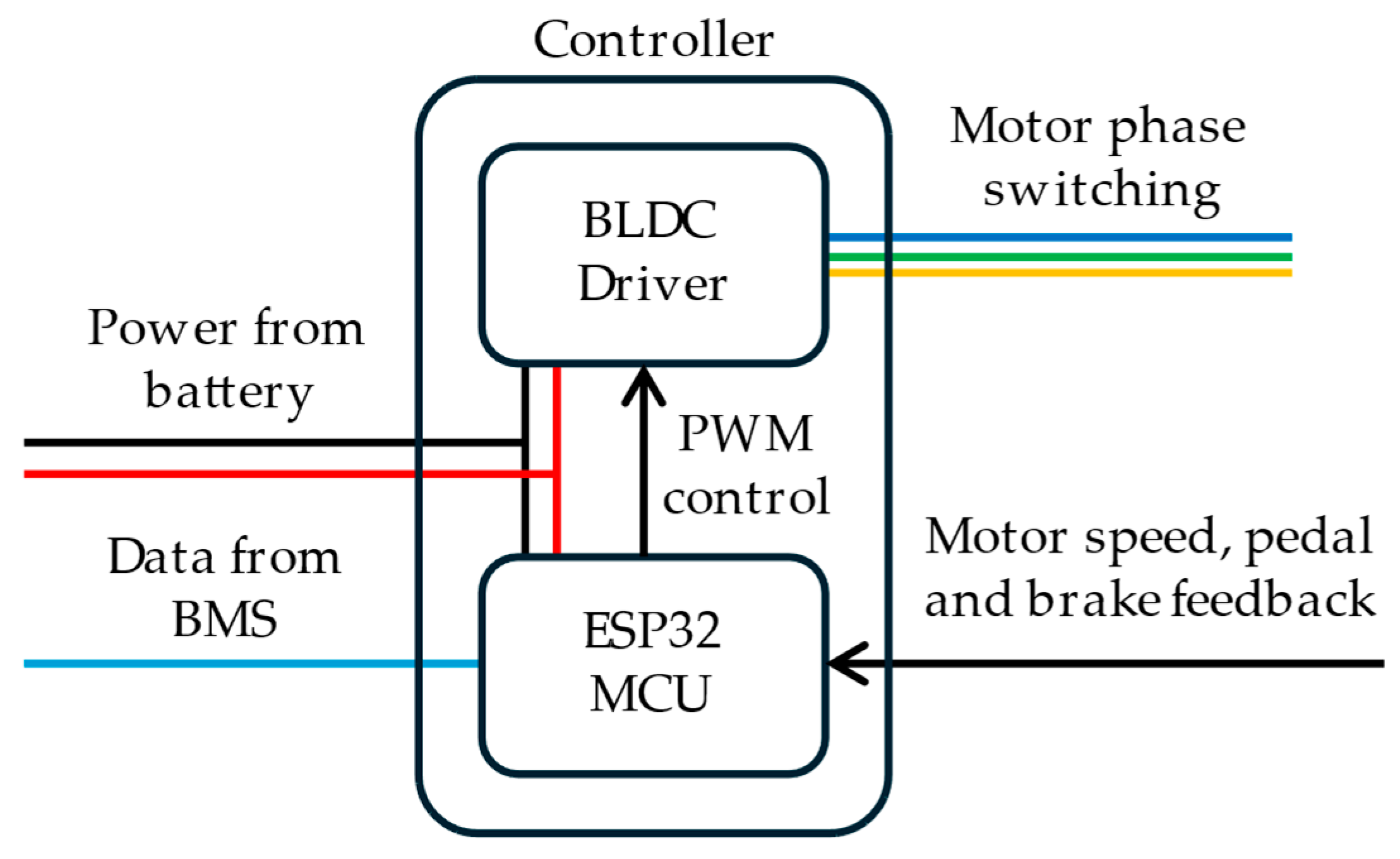
The controller consists of an off-the-shelf brushless direct current (BLDC) motor driver and an ESP32 microcontroller. While the BLDC driver is responsible for motor position detection and phase switching, the microcontroller governs the driver through a simple pulse width modulation (PWM) signal. Additionally, it retrieves critical battery parameters from the BMS such as battery temperature via serial communication and takes readings from the pedal and brake sensors to determine when motor assistance should be applied.
Figure 1 presents the controller architecture.
2.2. Thermal Management Algorithms
In this study, two distinct thermal management algorithms are proposed and developed: a reactive algorithm and a predictive algorithm. Both algorithms were implemented on the controller’s ESP32, which collects temperature data from the BMS and modifies the PWM output that controls the motor’s power.
The reactive algorithm continuously monitors battery temperature and reduces the maximum allowed speed as the temperature approaches a predefined critical threshold. This method prevents overheating by progressively scaling down the top speed of each assistance level, ensuring that power consumption decreases as the battery heats up. The speed adjustment follows Equation (1),
where
Vnew (km/h) is the adjusted top speed for the current assistance level,
Vbase (km/h) is the nominal top speed of the selected assistance mode,
Tbattery (°C) is the current battery temperature,
Tsafe (°C) is the temperature below which no reduction occurs and
Tcritical (°C) is the temperature at which maximum speed reduction is applied. It is important to note that the algorithm only operates when
Tbattery >
Tsafe. If it were to modify speed when the temperature is below this threshold, the adjusted speed could exceed the legal limits set for e-bikes. Thus, for temperatures below
Tsafe, the e-bike operates at full performance with no speed adjustments. While this approach may effectively prevent overheating, it reacts only to present temperature values and does not anticipate future trends. If the battery heats up rapidly, the system may not limit performance early enough to avoid exceeding critical temperatures.
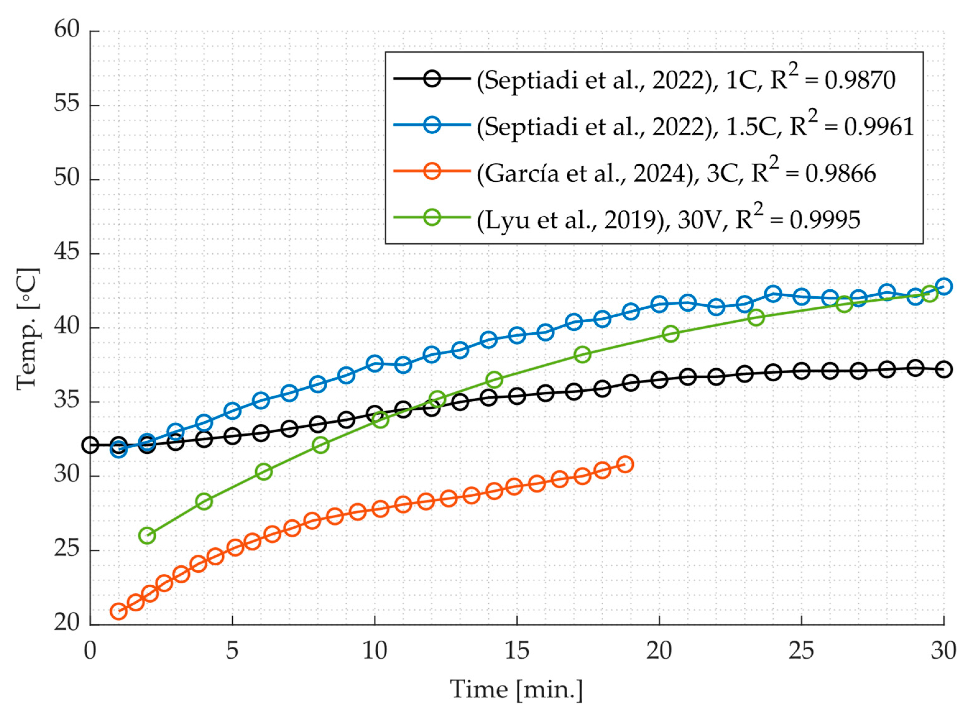
To overcome this limitation, a predictive algorithm is also proposed, which forecasts temperature evolution over time and adjusts speed in advance. Experimental data from previous studies [
13,
14,
17] indicate that battery temperature evolution follows a characteristic curve that can be effectively approximated by a second-degree polynomial when a cooling system is not employed, as illustrated by
Figure 2.
Given this observation, a quadratic regression model is employed to estimate the battery temperature at a future time
t, based on past and real-time temperature measurements. The temperature evolution is expressed as
where
Tpred(
t) is the predicted battery temperature at time
t, and
a,
b, and
c are regression coefficients obtained from past temperature data. The data used to fit this polynomial is composed of a series of temperature–time pairs (
ti,
Ti), where
ti is the time at which the temperature
Ti was measured. To compute the coefficients
a,
b, and
c, the least squares method is applied. This method minimizes the sum (
S) of squared residuals, which is the difference between the observed temperature values and the temperatures predicted by the polynomial model. The error equation to be minimized is given by
To minimize this error equation, the partial derivatives with respect to
a,
b and
c are taken and set equal to zero, and the resulting system of equations is solved. The equations for second-degree polynomial regression are
where
N is the number of data points. These equations form a system that can be solved for
a,
b and
c. The system can be expressed in matrix form as
or
The system is solved using Cramer’s Rule, which involves computing the determinants of the coefficient matrices. The solution for each variable
a,
b, and
c is given by equations x, y and z, respectively:
where
Aa,
Ab, and
Ac are matrices formed by replacing the corresponding column in
A with the constants from vector
B. While this regression model can be implemented on most microcontrollers, it is important to ensure adequate floating-point precision, as rounding errors may affect the accuracy of the computed polynomial coefficients. Using double-precision floating-point, as supported by the ESP32 microcontroller, helps maintain accurate temperature predictions and prevents potential miscalculations due to rounding errors. Through preliminary experimental testing, the regression model was found to be adequate for this application since the computation time for a regression with 30 datapoints was less than 1 millisecond.
Using this model, the algorithm continuously predicts the battery temperature for a predefined future time interval Δt. If the forecasted temperature Tpred(t + Δt) exceeds the critical threshold Tcritical, the system reduces the top speed of the current assistance level to ensure that overheating is prevented. In the same way as the reactive algorithm, the speed remains unchanged as long as Tpred(t + Δt) is below Tsafe, ensuring that performance is only limited when necessary. However, if performance is currently being limited and a new temperature forecast indicates that the battery’s thermal limit will no longer be reached, the system responds by gradually increasing the speed to restore performance while maintaining safe operating conditions.
2.3. Experimental Setup
To ensure accurate results in real usage scenarios, an e-bike prototype was constructed and tested using a cycling training roller. The prototype was built by integrating a custom lithium-ion battery and display, both developed specifically for this study. The battery was designed with a modular architecture, maintaining a fixed configuration of 10 cells in series for a nominal voltage of 36 V while allowing up to 3 cells in parallel. This flexibility enables easy adjustment of the total capacity to test different configurations and discharge rates. The lithium-ion cells used are Tenpower INR21700-50ME, with specifications detailed in
Table 1.
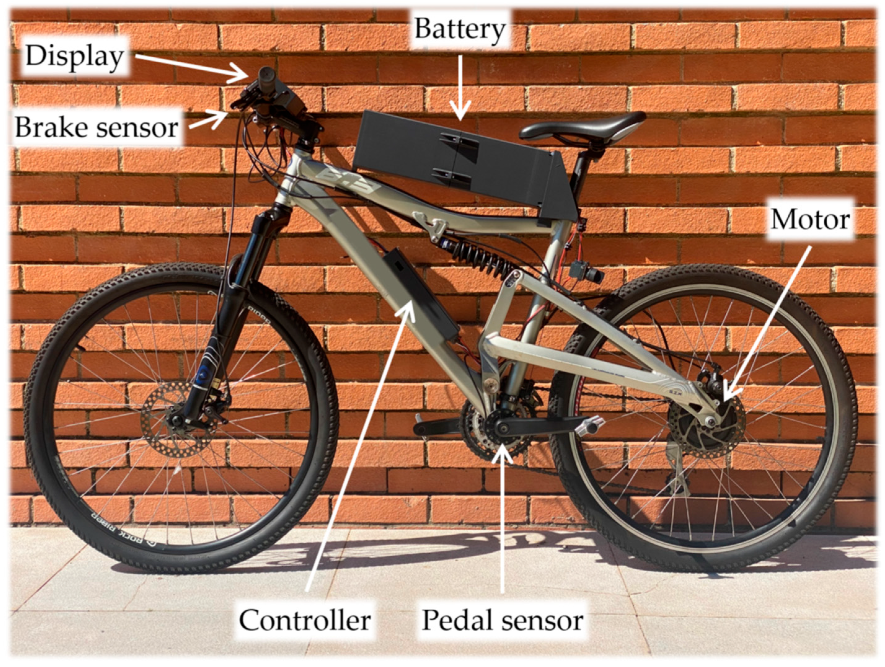
These components were installed on a conventional bicycle, which was also equipped with a commercially available e-bike motor mounted on the rear wheel. Additionally, the bike was fitted with a pedal sensor to detect rider input and brake sensors that signal the controller to cut motor power when braking. While the battery is typically located at the bottom of e-bike frames, in this case, it was installed on top to provide easier access for maintenance and quick disassembly when necessary, as well as to simplify component replacement and upgrades during experimental testing. The e-bike prototype is shown in
Figure 3.
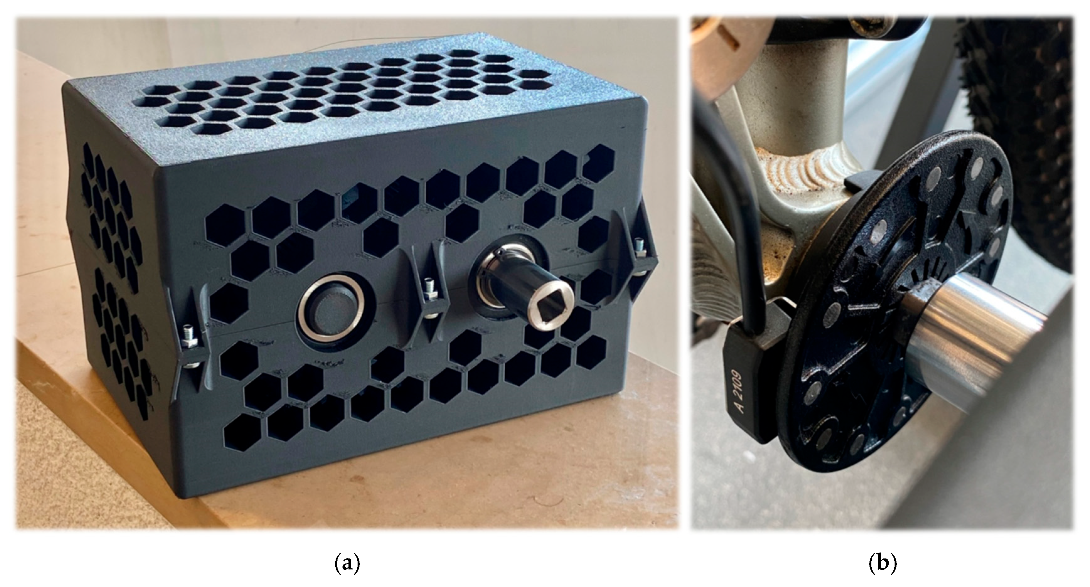
To achieve consistency with commercial controllers and compliance with legal regulations, a pedaling mechanism was designed and constructed to simulate user pedaling. This setup allowed the e-bike motor to provide assistance under realistic operating conditions. Like the motor controller, the pedaling mechanism consists of a BLDC motor, a motor driver, and an ESP32 microcontroller, which regulates the pedaling speed. For integration with the e-bike, a custom output shaft was designed and manufactured to connect to the pedal shaft. The left pedal was removed, and the pedaling mechanism was installed in its place.
Figure 4a shows the pedaling mechanism, while
Figure 4b illustrates its attachment to the e-bike, replacing the left pedal.
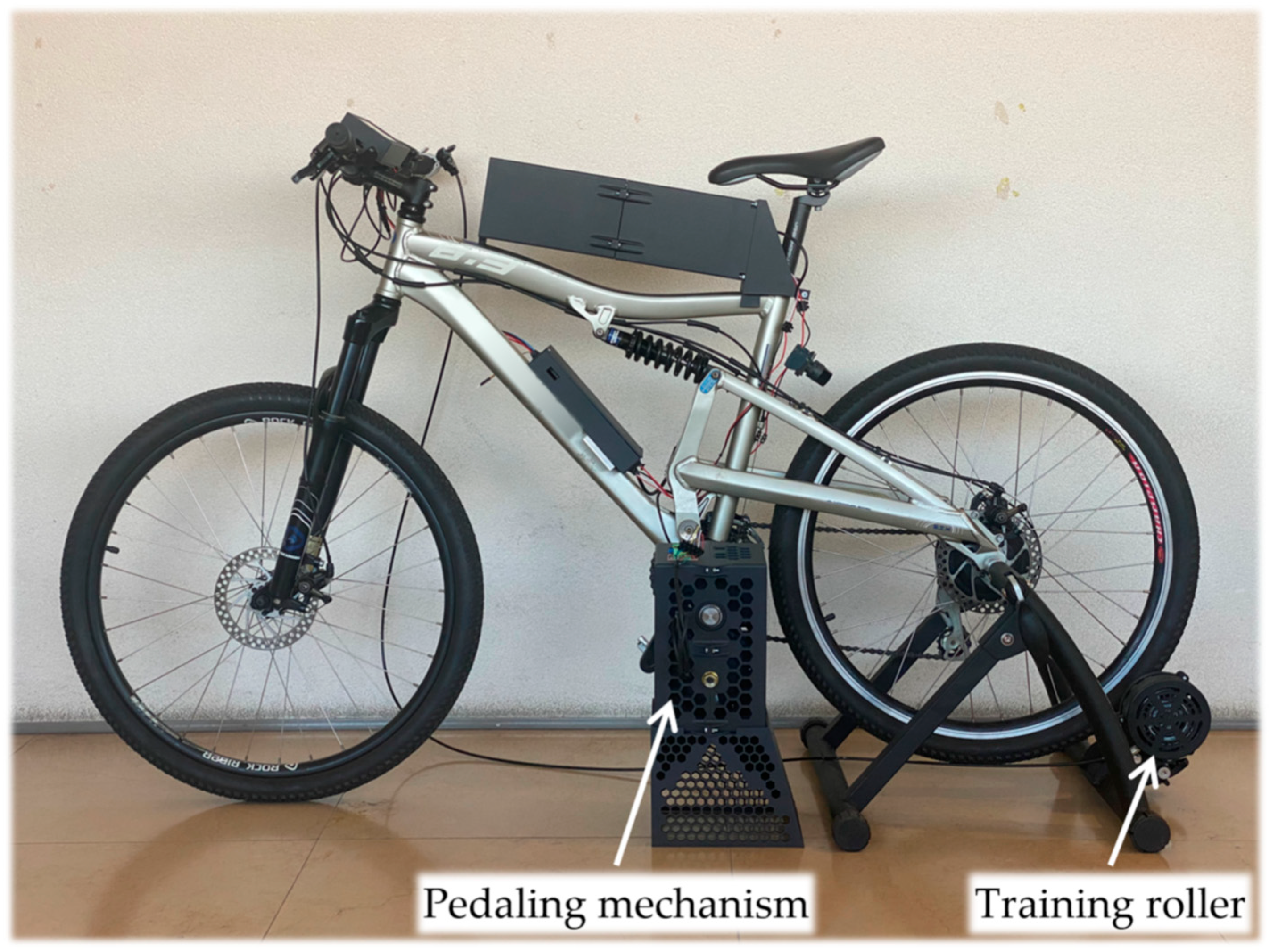
Finally, the e-bike prototype was installed on a cycling training roller with variable magnetic resistance, along with the pedaling mechanism prototype. The experimental setup can be seen in
Figure 5.
One of the limitations of indoor testing is the absence of air resistance and wind, which contribute significantly to the motor’s power demand. To account for these factors, additional tests were conducted on the road, where the average power consumption values were measured. During these tests, an assistance level was selected, and pedaling was initiated to activate motor assistance. The vehicle was then allowed to accelerate until the designated speed for the selected assistance level was reached and maintained. Once the target speed was achieved, a function on the microcontroller began recording power consumption data, calculating the average value over a 10-s period. The results of these measurements are presented in
Table 2.
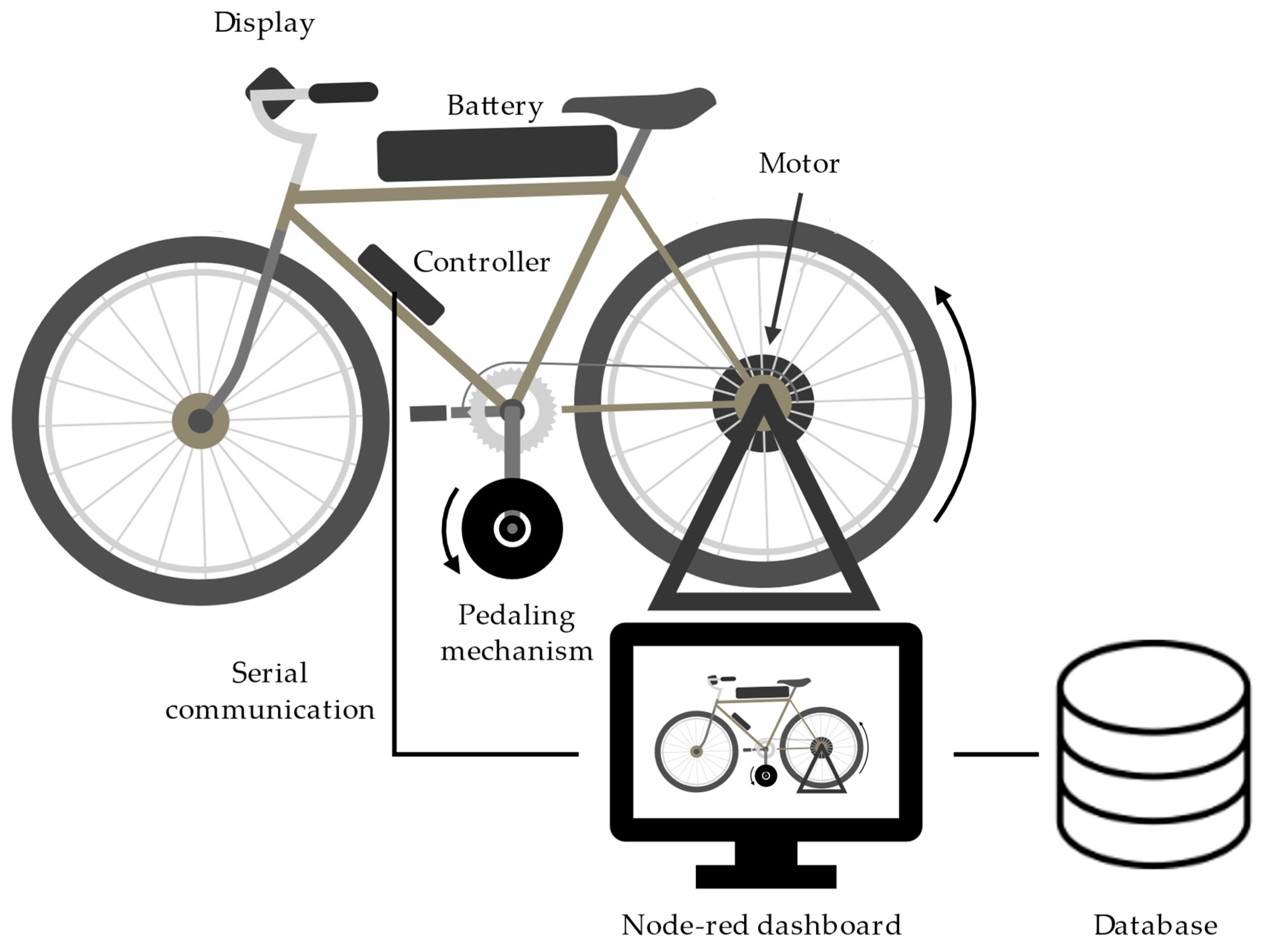
Finally, a data acquisition system was developed to collect relevant data during testing. The data is transmitted via serial communication from the ESP32-based controller. A Node-RED dashboard was implemented to manage the incoming data, visualize it in real time, and store it in a database. Additionally, the system allows control over the selected assistance level and the frequency of data transmission. The speed of the pedaling mechanism, however, must be adjusted manually. In
Figure 6, a schematic of the experimental setup with the data acquisition system is shown.
3. Experimental Results
Since the battery operates at a nominal voltage of 36 V with a maximum power of 224 W, a 10s1p configuration was selected for testing, resulting in a nominal discharge rate of 1.25 C. While typical e-bikes often use parallel cell configurations to increase capacity, this setup was suitable for experimental purposes. Testing at this discharge rate allowed for validating the proposed models under different usage conditions, such as hill climbing. Additionally, cargo e-bikes, which have higher weight but similar top speeds, can experience comparable discharge rates, further supporting the relevance of this test configuration.
Several tests were conducted to evaluate the effectiveness of the proposed algorithms for thermal management. All tests were performed at assistance level 5 and had a maximum duration of 30 min to allow for comparison with existing literature. To ensure consistency, all tests were performed at a room temperature of 22 °C.
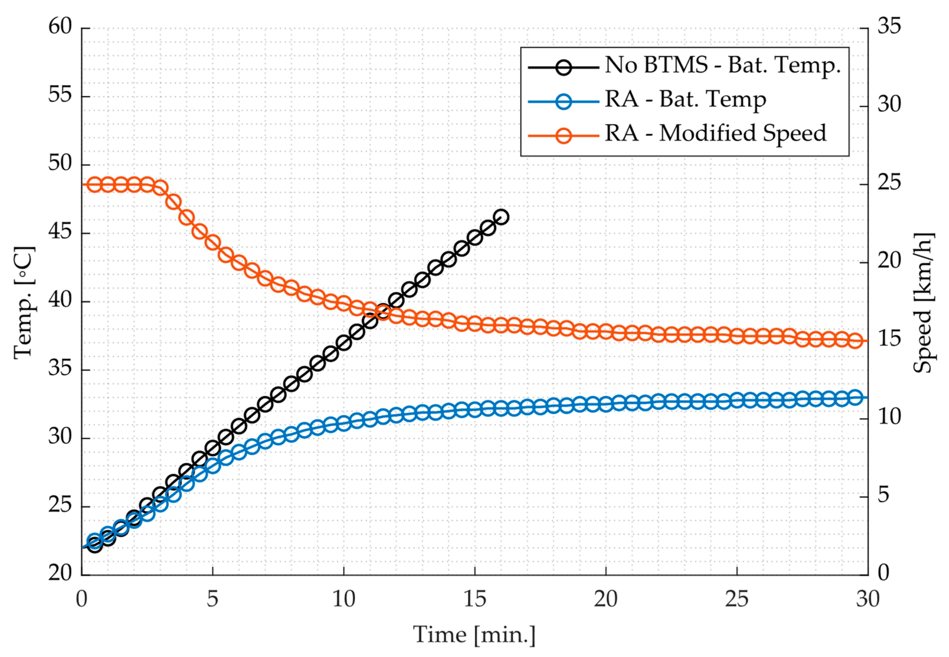
First, two tests were carried out. In the first test, the e-bike was set to operate at a constant speed without any thermal management system, relying solely on the BMS to cut off power if the temperature reached dangerous levels. In contrast, the second test was conducted using the reactive algorithm (RA) with speed limitation. The safe and critical temperatures used in the algorithm, as defined in Equation (1), were set to 25 °C and 45 °C, respectively. The critical temperature of 45 °C was chosen as it corresponds to the maximum allowed operating temperature for the used cells. The computed speed (
Vnew) was rounded to one decimal place, as this was the highest resolution supported by the system. The results of both tests are presented in
Figure 7.
As the results from the first test show, a thermal management system is essential at the selected discharge rate. The battery temperature continuously increased throughout the test and reached 47 °C after approximately 16 min, at which point the BMS interrupted power delivery to prevent overheating. In contrast with results reported by other authors, the temperature evolution in this test followed an almost linear pattern. This behavior can be explained by the fact that, similar to conventional e-bikes, the battery cells were fully enclosed. As a result, the increase in heat transfer due to a growing temperature difference with the surrounding air did not occur, since the plastic enclosure prevented effective convective cooling. Nonetheless, the second-degree polynomial regression model was retained to ensure that the model remained applicable to a broader range of conditions beyond the specific setup tested in this work. Although the experimental data displayed near-linear behavior, fitting a second-degree polynomial yielded an R2 coefficient of 0.999520, indicating excellent approximation. In such cases, the quadratic term is very small and has a negligible impact on predictive performance, but its inclusion provides flexibility to capture potential nonlinear trends under different configurations.
In contrast, the results from the second test show that the reactive algorithm was successful in preventing the battery from reaching its thermal limit. After 30 min of operation, the battery temperature was 33 °C, rising slowly and steadily throughout the test. However, this performance came at the cost of a 40% reduction in top speed, with the system limiting the speed to approximately 15 km/h by the end of the test. This outcome highlights a limitation of the simple reactive algorithm. In this case, the temperature could have continued to rise within safe margins, allowing for higher speeds and consequently shorter travel times.
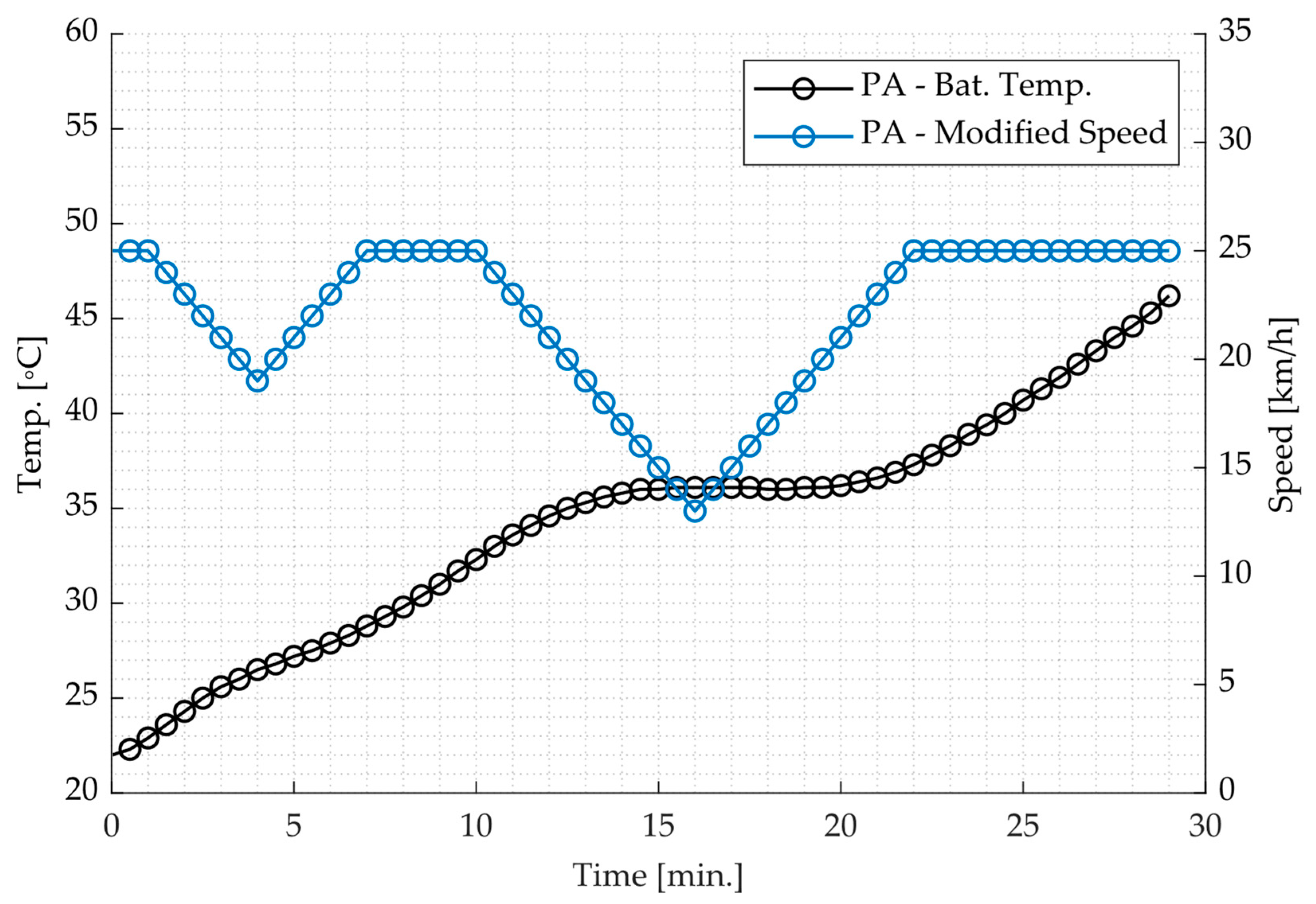
Considering the results and identified limitations, a third test was conducted using the predictive algorithm (PA) implemented on the microcontroller. In this approach, the algorithm continuously analyzes all temperature data gathered since the beginning of the test and attempts to forecast the battery temperature after a total of 30 min of operation. If the predicted temperature exceeds the critical threshold, the system reduces the speed by 1 km/h. Otherwise, if the predicted temperature remains below the critical value, the speed is incrementally increased by 1 km/h, up to a maximum of 25 km/h. This evaluation and adjustment process is performed at 30-s intervals throughout the test. The results of this test are presented in
Figure 8.
The results indicate that when considering all previous data, the predictive algorithm is not able to keep the battery temperature within safe limits. The test was interrupted by the BMS at the 29-min mark due to the temperature exceeding the critical threshold. Additionally, the temperature rise was unstable, and the speed adjustments made by the algorithm resulted in significant oscillations. These large fluctuations in speed are undesirable for practical e-bike usage, as they negatively affect ride comfort and overall user experience. This behavior can be explained by the prediction method’s low responsiveness, as it used all data points from the start of the test. This made it slow to adapt to recent temperature changes, resulting in overcorrections and large speed oscillations.
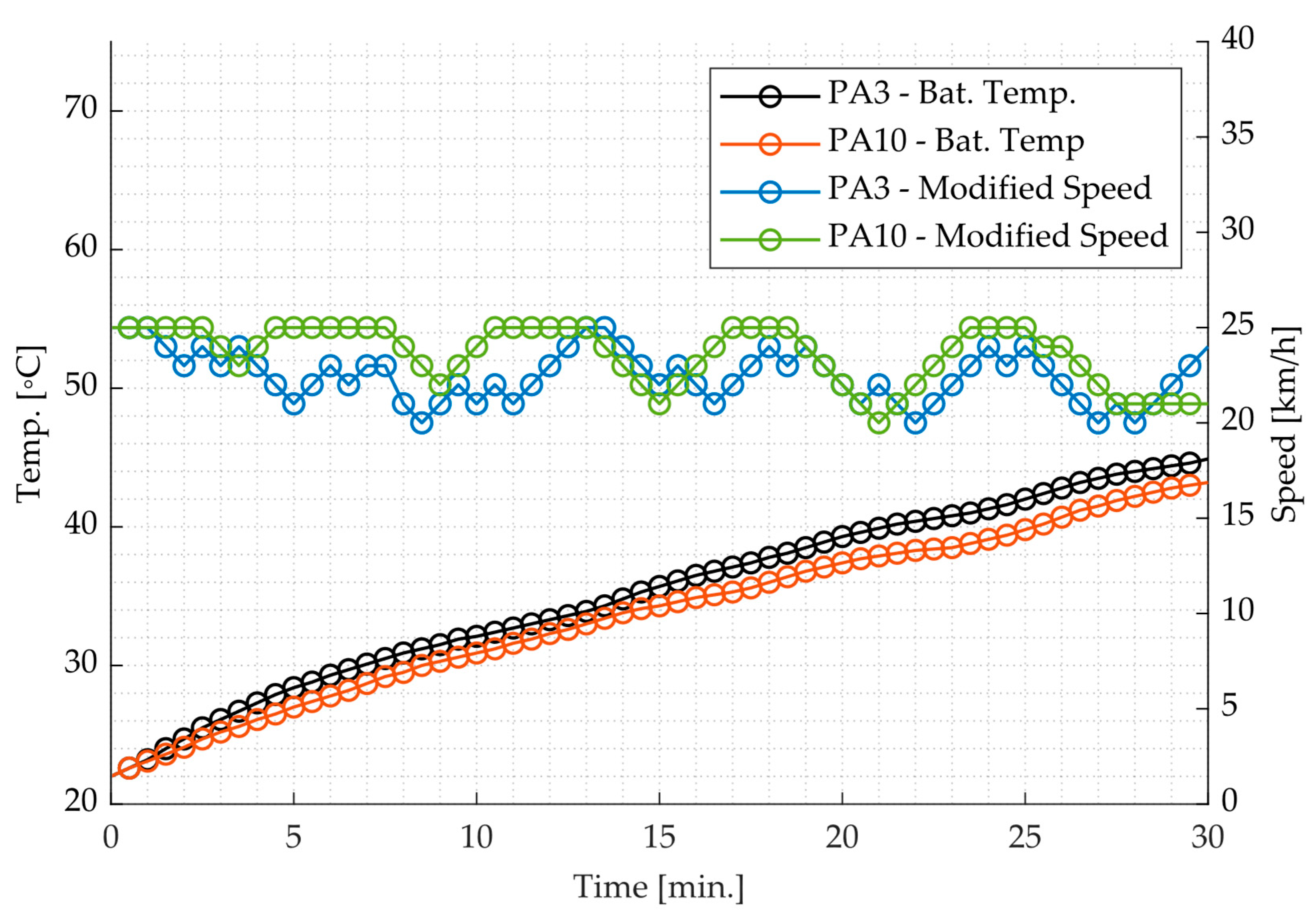
To improve accuracy, two final tests were conducted using only the last 3 (PA3) or 10 (PA10) data points for prediction. In cases where 10 data points were not available, the model considered all the available data points up to that moment. Furthermore, to minimize speed oscillations, a target temperature range was introduced. When the predicted temperature fell within this range, which in this case was set between 43 °C and 45 °C, no speed adjustments were made, reducing unnecessary fluctuations when the system was already near the desired thermal limit. The results of both these tests are presented in
Figure 9.
The final test results show that in both cases, the algorithm performed better compared to the baseline predictive model, since in both tested models the temperature rose steadily without surpassing the safe limit. While the PA3 model exhibited a 4% higher peak temperature and pronounced speed oscillations, the PA10 model maintained lower operating temperatures and achieved five distinct periods of constant speed, contributing to significantly improved user comfort and ride stability.
4. Conclusions
In this study, a microcontroller-based e-bike controller was developed to integrate thermal management algorithms, addressing the limitations of conventional e-bike systems. The controller, built around an ESP32 microcontroller, enables the implementation of thermal management algorithms to optimize battery temperature. Two algorithms were developed: a reactive one that adjusts speed based on real-time battery temperature and a predictive one that forecasts temperature changes and adjusts speed in advance to prevent overheating.
Experimental tests demonstrated that the reactive algorithm effectively controlled battery temperature by reducing speed as it approached the critical limit, stabilizing at a temperature 26.7% lower than the maximum threshold. However, this came at the cost of significant speed reductions, reaching up to 40.0%. The predictive algorithm, on the other hand, showed to be promising by adjusting speed proactively based on temperature forecasts. However, it caused instability, leading to large fluctuations in speed, which negatively impacted ride comfort. To address this, further tests were conducted using a reduced number of recent data points for prediction and introducing a target temperature range to reduce speed oscillations. The final results showed that both predictive models, PA3 and PA10, limited speed by a maximum of 20% and outperformed the baseline model. Among them, PA10 provided the best balance between stable temperatures and consistent speed, resulting in improved user comfort.
In conclusion, the microcontroller-based thermal management system proved to be effective in controlling battery temperature, with the predictive algorithm showing potential for further refinement. Additional improvements and testing are needed to optimize its performance for practical e-bike use.


