Article

Demagnetization Fault Diagnosis for PMSM Drive System with Dual Extended Kalman Filter

1
Tianjin Key Laboratory of Intelligent Control of Electrical Equipment, Tiangong University, Tianjin 300387, China
2
Zhejiang University Advanced Electrical Equipment Innovation Center, Zhejiang University, Hangzhou 311107, China
*
Author to whom correspondence should be addressed.
World Electr. Veh. J. 2025, 16(2), 112; https://doi.org/10.3390/wevj16020112
Submission received: 27 January 2025 / Revised: 8 February 2025 / Accepted: 17 February 2025 / Published: 18 February 2025

Abstract

:
Aiming at the irreversible demagnetization of permanent magnet synchronous motors (PMSMs) under extreme working conditions, a fault diagnosis method for permanent magnet demagnetization based on multi-parameter estimation is proposed in this paper. This scheme aims to provide technical support for enhancing the safety and reliability of permanent magnet motor drive systems. In the proposed scheme, multiple operating states of the motor are acquired by injecting sinusoidal current signals into the d-axis, ensuring that the parameter estimation equation satisfies the full rank condition. Furthermore, the accurate dq-axis inductance parameters are obtained based on a recursive least square method. Subsequently, a dual extended Kalman filter is employed to acquire real-time permanent magnet flux linkage data of PMSMs, and the estimation data between the two algorithms are transferred to each other to eliminate the bias of permanent magnet flux estimation caused by a parameter mismatch. Finally, accurate evaluation of the remanence level of the rotor permanent magnet and demagnetization fault diagnosis can be achieved based on the obtained permanent magnet flux linkage parameters. The experimental results show that the relative estimation errors of the dq-axis inductance and permanent magnet flux linkage are within 5%, which can realize the effective diagnosis of demagnetization fault and high-precision condition monitoring of a permanent magnet health.

1. Introduction

Permanent magnet synchronous motors (PMSMs) utilize permanent magnet excitation, without excitation winding, and a collector ring and brush device. This design offers several advantages, including a simple structure, low maintenance cost, wide speed range and other significant benefits, which can adapt to the strict technical requirements of many fields such as new energy vehicles, precision computer numerical control (CNC) machining tools, aerospace, and artificial intelligence [1,2]. However, due to the unique material characteristics of permanent magnets, they are susceptible to high temperature, chemical corrosion, an armature reaction and mechanical vibration, which can lead to irreversible demagnetization faults in PMSMs [3,4]. More importantly, the irreversible demagnetization faults can lead to disturbances in inductance and flux linkage parameters, degrading the output torque performance of the motor. Consequently, this negatively impacts the stability of the PMSM drive system and its high-precision output [5]. Therefore, to ensure the safe and reliable operation of PMSMs, it is urgent to conduct research on fault diagnosis and health management of PMSM rotor permanent magnets. This research will provide a foundation for subsequent motor condition monitoring and the development of fault-tolerant operation strategies after demagnetization faults.
Currently, the common demagnetization fault diagnosis systems primarily include a signal processing-based method, data-driven method, and model-based method. The diagnostic idea of the signal processing-based method involves utilizing advanced signal processing techniques to identify and extract characteristic variations in current and voltage signals before and after faults occur. By analyzing these signal changes, fault indices and thresholds are established, so as to achieve accurate demagnetization fault diagnosis [6]. Reference [7] integrated three signal processing technologies, namely the adaptive demodulation, the time-varying resampling, and the envelope analysis, which effectively enhanced the capability to detect and identify stator current characteristics after demagnetizing faults. In reference [8], the frequency domain deviation of zero-sequence voltage before and after a demagnetization fault is analyzed using the fast Fourier transform (FFT) algorithm to achieve demagnetization diagnosis. However, zero-sequence voltage cannot be directly measured in existing drive systems, which poses significant challenges for the practical implementation of this algorithm in engineering applications. A demagnetization fault detection method based on noise signal analysis is proposed in reference [9]. Seven acoustic indicators are developed by using advanced signal processing techniques, including Hilbert–Huang transform, power spectral density, and FFT, to achieve real-time monitoring of the magnet health. However, the fault sensitivity of characteristic variables associated with these methods can fluctuate in response to varying working conditions, which may potentially compromise the speed and accuracy of the fault diagnosis. In recent years, data-driven methods have gained widespread adoption in the fault diagnosis of PMSMs, further improving the safety and stability of motor drive system [10]. These methods do not require precise analytical models; instead, they rely on collecting various operational data from the motor during its operation and developing well-designed artificial intelligence models to achieve fault diagnosis and pattern recognition. In reference [11], a linear mapping relationship between demagnetization faults and torque harmonics was established, and a basic dynamic Bayesian neural network was employed to accomplish the diagnostic objective. A random forest approach was employed by reference [12] to adaptively extract characteristic harmonics from induced voltage signals, thereby achieving efficient differentiation of various demagnetization fault modes. The direct relationship between the preset fault indicators and the demagnetization fault types is established by the knowledge graph intelligent algorithm [13], and the online diagnosis of demagnetization faults of permanent magnet motors is realized. A fault diagnosis model utilizing a one-dimensional convolutional neural network (CNN) is developed by reference [14]. The stator current data of the motor can be directly input into the CNN to classify and identify demagnetization faults, without the need for an in-depth analysis of the fault mechanism. In reference [15], the air gap magnetic flux density is utilized as the fault signal. Fault feature reconstruction and extraction are conducted, and demagnetization fault diagnosis is ultimately achieved through integration with a random forest intelligent algorithm. The thermal effects associated with demagnetization in PMSMs are analyzed in reference [16]. Furthermore, an intelligent diagnosis system for demagnetization faults was developed, utilizing motor temperature signals and a backpropagation neural network. However, the accuracy of the fault diagnosis may be compromised due to the presence of mixed redundant signals and other interference components within the one-dimensional time domain signals. To address this issue, magnetic flux leakage signals before and after demagnetization faults are visualized in two dimensions by employing a high-dimensional mapping algorithm, as reported in references [17,18]. By applying image coding technology, this approach mitigates the computational burden associated with complex feature vectors during image content retrieval, thus enhancing fault diagnosis performance across various operating conditions. In reference [19], a finite element analysis model of PMSMs incorporating demagnetization faults is developed, from which air-gap magnetic density signals from three lines are extracted. The pixel density of the diagonal element contour surface is then obtained through digital image processing techniques as the fault feature. Subsequently, demagnetization fault diagnosis is achieved by integrating the algorithm of an extreme learning machine. A multi-sensor heterogeneous information fusion framework that integrates high-dimensional data from the stator current and torque to generate fault criteria is introduced by reference [20], thereby enabling automatic diagnosis and classification of demagnetization fault modes. However, the widespread adoption of this algorithm continues to be impeded by the limitations in edge computing capabilities.
Model-based diagnosis methods utilize the electromagnetic relationships and system parameters within the motor to construct fault models. By combining with the motor parameter estimation or state observation algorithms, these methods enable an in-depth analysis of the health status of the permanent magnet flux, to achieve a precise demagnetization fault diagnosis [21,22]. A flux linkage identification method utilizing a split-step strategy is proposed in reference [23]. A high-frequency signal injection is integrated with DC bias injection by this method, thereby enabling online decoupling of the flux linkage parameter and enhancing the precision of the flux linkage identification. In reference [24], a demagnetization fault diagnosis method with an adaptive learning ability is proposed. The adaptive rate of the model reference adaptive system (MRAS) is designed using adaptive linear neurons to improve the accuracy of the flux linkage observation. However, the MRAS algorithm can be adversely affected by harmonics and noise during the computation process. Therefore, it is generally advisable to incorporate additional low-pass filters to preprocess the dq-axis voltage and current signals prior to initiating the algorithm. In references [25,26], a state observer which can estimate the dynamic change of the flux linkage in real time is constructed to realize the diagnosis and quantification of demagnetization faults according to the sliding mode variable structure theory. Similarly, reference [27] integrates the sliding mode observer with the Luenberger observer to mitigate the chattering effect inherent in the sliding mode observer and effectively isolate the negative influence of the rotational speed on the observer. This integration enhances the stability of the state observation process after demagnetization faults.
However, the aforementioned demagnetization fault diagnosis schemes focus exclusively on the flux linkage variation induced by demagnetization effects while neglecting the coupled relationship between inductance and flux linkage. Consequently, a demagnetization diagnosis scheme based on parameter estimation is proposed in this paper. Specifically, the scheme acquires the multi-group operating status of the motor by injecting a sinusoidal current signal into the d-axis to satisfy the full-rank condition required for parameter estimation. Moreover, a recursive least squares (RLS) algorithm is used to accurately estimate the inductance of the dq-axes. Subsequently, a flux linkage observer based on the dual extended Kalman filter (DEKF) is developed, comprising two interconnected filters that can precisely estimate the average residual magnetic field intensity of the rotor permanent magnets. Ultimately, the estimation results from both algorithms are cross-transmitted to mitigate the impact of parameter perturbations caused by demagnetization faults on the final flux linkage estimation.

2. Parameter Mismatch Caused by Demagnetization

When the motor is undergoing acceleration or operating under a high load, a significant amount of heat is generated within the motor. A high temperature can perturb the flux linkage of the permanent magnets, leading to a reduction in the average residual magnetic field strength of the rotor permanent magnets and causing irreversible demagnetization. The linear thermal model for the flux linkage is
ψ m = ψ m 0 1 + η T T 0
where ψm is the actual value of the flux linkage when the permanent magnet temperature is T, ψm0 is the nominal value of the flux linkage when the permanent magnet temperature is T0. η is the thermal coefficient of the permanent magnet flux linkage, usually taking the value −0.12%/°C. Considering the small value of η, it can be approximated that only constant disturbance exists in ψm under the demagnetization fault, i.e.,
ψ m = ψ m 0 + Δ ψ m
where Δψm represents the flux linkage disturbance value caused by the demagnetization effect.
The stator inductance calculated by the finite element method can be expressed as
L s = 2 L ef l = 1 H l B l Δ S l 3 i s 2
where Ls and Lef represent the stator inductance and core length, is is the stator current, Hl, Bl, and Bl represent the magnetic field strength, remanence density, and computational element area corresponding to the l-part finite element mesh subdivision, respectively. In a healthy motor, the internal magnetic field energy storage remains stable, and the inductance does not exhibit significant variation. However, when demagnetization faults occur, the faulted permanent magnets and the associated air-gap magnetic fields are weakened to varying degrees. Concurrently, the flux density between the motor’s air-gap, stator teeth, and stator yoke, corresponding to the faulty permanent magnet, changes with the degree of demagnetization. At this time, the actual inductance value deviates from its nominal value, which can be expressed as follows
L d = L d 0 + Δ L d , L q = L q 0 + Δ L q
where Ld0 and Ld0 represent the nominal values of the dq-axis stator inductance, respectively. ΔLd and ΔLq represent the disturbance values of the dq-axis stator inductance caused by the demagnetization effect, respectively.
By introducing (2) and (4) into the voltage equation of PMSMs, it can be obtained that
d d t i d = R s L d 0 i d + L q 0 L d 0 ω e i q + 1 L d 0 u d + ζ d d d t i q = R s L q 0 i q L d 0 L q 0 ω e i d + 1 L q 0 u q ψ m 0 L q 0 ω e + ζ q
where ud, uq, id, and iq represent the stator voltage and current of the dq-axis, respectively, and we is the electrical angular velocity. ζd and ζq represent the dq-axis perturbations, respectively, which are induced by the demagnetization effect; this can be expressed as follows
ζ d = Δ L d L d 0 L d 0 + Δ L d u d R s i d + L q 0 ω e i q + Δ L q ω e i q + Δ L q ω e i q L d 0 ,
ζ q = Δ L q L q 0 L q 0 + Δ L q u q R s i q L d 0 ω e i d Δ L d ω e i d ω e ψ m 0 ω e Δ ψ m 0 Δ L d ω e i d + ω e Δ ψ m 0 L q 0 .
Further, the mechanical motion equation and electromagnetic torque equation of PMSMs can be obtained
d d t ω e = p J T e T L B ω T e = 1.5 p ψ m 0 + L d 0 L q 0 i d i q + ζ e
where p denotes the number of pole-pairs, J represents the rotational inertia, B is the viscous friction coefficient, and w = pwe denotes the mechanical angular velocity. Te and TL are the electromagnetic torque and load torque of the motor output, respectively, and ζe = 1.5pψm + (ΔLd − ΔLq)id]iq denote the electromagnetic torque disturbance.

3. Proposed Demagnetization Fault Diagnosis Method

3.1. Inductance Calculation Based on Recursive Least Square

To achieve a precise estimation of the dq-axis inductance, this paper designs an inductance estimation method based on a d-axis sinusoidal current signal injection and the least square algorithm. In this method, multiple sets of motor operation data are collected by injecting a sinusoidal current signal into the d-axis of the motor, thereby ensuring a full-rank solution during the inductance estimation process. Furthermore, the dq-axis inductance is obtained in real time through RLS.
The calculation formula for the RLS algorithm can be expressed as follows
ρ ^ k = ρ ^ k 1 + V k y 1 , k φ k T ρ ^ k 1 W k = γ 1 I V k φ k T W k 1 V k = W k 1 φ k γ + φ k T W k 1 φ k 1
where k is the kth sampled data. γ is the forgetting factor, which is usually between 0.2 and 0.8. W0 is usually defined as W0 = UI, I is the identity matrix, and the value range of U is between 104 and 106.
The dq-axis inductance estimators are designed according to Equation (7), and the Ld estimator can be expressed as
L ^ d , k = L ^ d , k 1 + V L d , k y L d , k φ L d , k T L ^ d , k 1
where
y L d , k = T s u q , k 1 T s R s i q , k 1 L q i q , k i q , k 1 T s ω e , k 1 ψ m ,   φ L d , k T = T s ω e , k 1 i d , k 1 .
The Lq estimator can be expressed as
L ^ q , k = L ^ q , k 1 + V L q , k y L q , k φ L q , k T L ^ q , k 1
where
y L q , k = T s u d , k 1 T s R s i d , k 1 L d i d , k i d , k 1 ,   φ L q , k T = T s ω e , k 1 i q , k 1 .

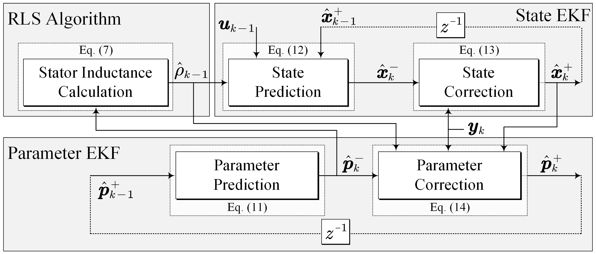
3.2. Flux Linkage Estimatation Based on Dual Extended Kalman Filter

Figure 1 illustrates the proposed demagnetization fault diagnosis method based on the DEKF. This method mainly includes two parts: one EKF is employed to estimate the current dynamics, and the other is utilized to estimate the permanent magnet flux linkage of the motor.
The DEKF state space equation for flux linkage estimation can be expressed as
x k = g x k 1 , p k 1 , u k 1 + w x , k 1 p k = p k 1 + w p , k 1 y k = H x k , p k + v k
where xk = [id,k iq,k]T, uk = [ud,k uq,k]T, and yk = [id,k iq,k]T are the state vector, input vector and output vector, respectively, and pk = ψm,k is the permanent magnet flux linkage to be estimated. wx,k−1 and wp,k−1 are the system process noise and vk is the system measurement noise.
The DEKF algorithm is calculated as follows, where the superscript “+” indicates the DEKF correction value, and the subscript “-” indicates the predicted DEKF value.
Step I: Parameter Prediction.
p ^ k = p ^ k 1 + P p , k = P p , k 1 + + Q p , k
Step II: State Prediction.
x ^ k = g x ^ k 1 + , p ^ k , u k 1 P x , k = G x , p , k 1 P x , k 1 + G x , p , k 1 T + Q x , k
where
G x , p , k 1 = g x , p ^ k , u k 1 x x = x ^ k 1 + = 1 R ^ s , k L d T s ω e , k 1 L q L d T s ω e , k 1 L d L q T s 1 R ^ s , k L q T s .
Step III: State Correction.
K x , k = P x , k H x , k T H x , k P x , k H x , k T + R k P x , k + = I K x , k H x , k P x , k x ^ k + = x ^ k + K x , k y k H x ^ k , p ^ k
where
H x , k = H x , p ^ k x x = x ^ k 1 + = 1 0 0 1 .
Step IV: Parameter Correction.
K p , k = P p , k H p , k T H p , k P p , k H p , k T + R k P p , k + = I K p , k H p , k P p , k p ^ k + = p ^ k + K p , k y k H x ^ k , p ^ k
where
H p , k = d y k d p p = p ^ k = H x ^ k , p p p = p ^ k + H x ^ k , p x ^ k d x ^ k d p p = p ^ k ,
d x ^ k d p = g x ^ k 1 + , p ^ k 1 + , u k 1 p + g x ^ k 1 + , p ^ k 1 + , u k 1 x ^ k 1 + d x ^ k 1 + d p ,   d x ^ k 1 + d p = d x ^ k 1 d p K x , k 1 d H x ^ k , p k d p ,
g x ^ k 1 + , p ^ k 1 + , u k 1 p = 0 T s ω e , k 1 L q T ,   g x ^ k 1 + , p ^ k 1 + , u k 1 x ^ k 1 + = 1 R ^ s , k 1 + L d T s ω e , k 1 L q L d T s ω e , k 1 L d L q T s 1 R ^ s , k 1 + L q T s .
In the initial startup phase of the algorithm,  d x ^ k 1 + / d p K x , k 1 , and  d H x ^ k , p k / d p  are initialized to a 2 × 2 all-zero matrix, respectively.
In (11) to (14), Qx,k and Qp,k denote the covariance matrices associated with the system noise, and Rk represents the covariance matrix corresponding to the measurement noise. Px,k and Pp,k represent the error covariance matrices of the states and parameters, respectively; Kx,k and Kp,k denote the Kalman gains for the states and parameters, respectively; Dx,p,k−1 are the Jacobian matrices of the function  g ( x , p ^ k , u k 1 )  with respect to x; Hx,k and Hp,k are the Jacobian matrices of the function H(xk, pk) with respect to x and p, respectively. By solving (11) to (14), an accurate estimation of the flux linkage parameters of permanent magnets can be obtained, and DEKF can be used to effectively monitor the remanence level of magnets. Finally, the inductance data estimated by the RLS algorithm and the flux linkage data estimated by the DEKF algorithm are transferred to each other. After compensating for deviations in permanent magnet flux parameters caused by mismatches in inductance parameters, the final permanent magnet flux parameters are utilized to diagnose and quantify demagnetization faults. The control block diagram of the proposed method is shown in Figure 2.

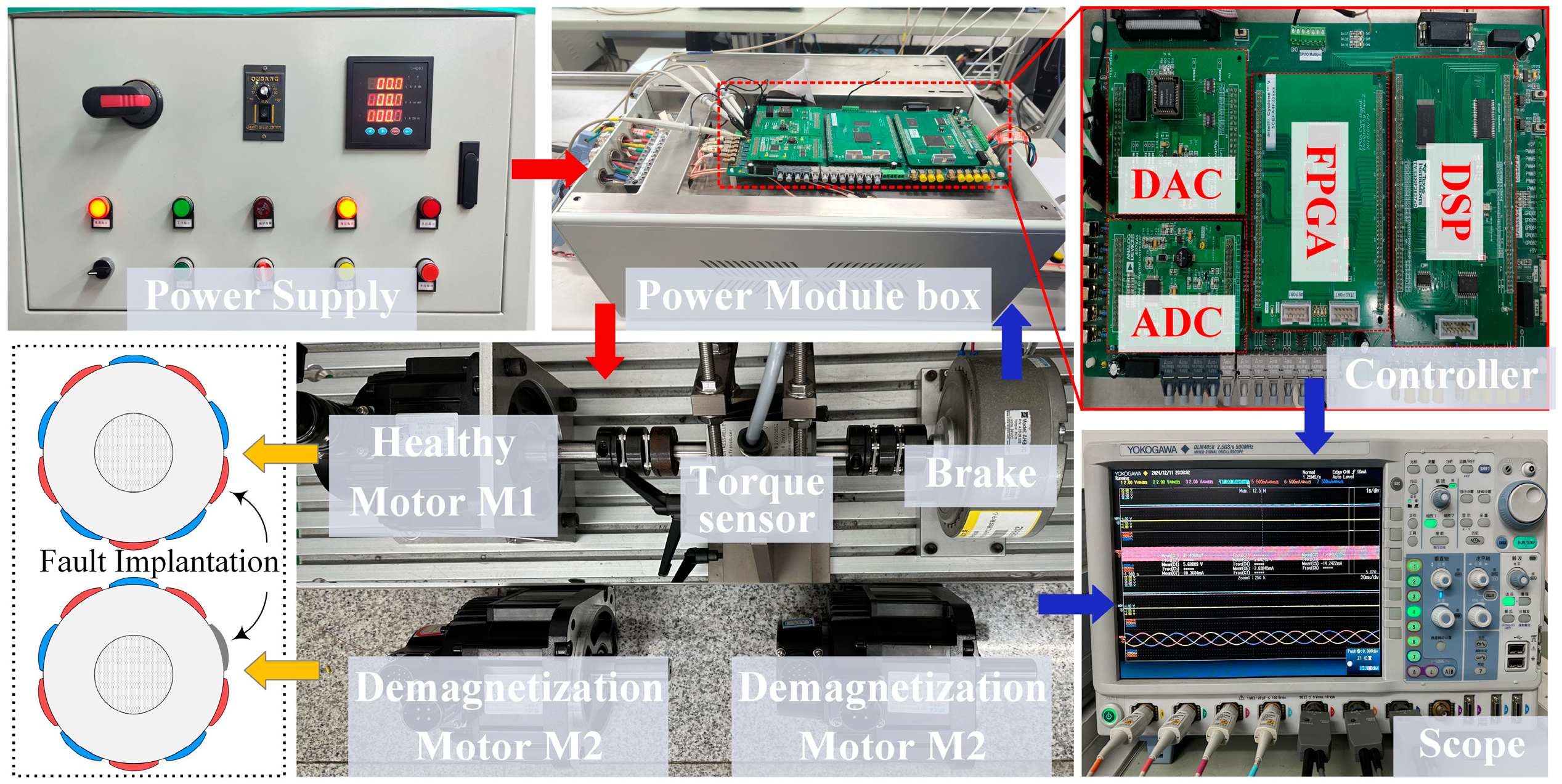
4. Experimental Results

To validate the feasibility and effectiveness of the proposed diagnosis method, three prototypes of PMSMs, designated as M1, M2, and M3, are fabricated. Specifically, to simulate local demagnetization faults, M2 and M3 are designed with varying magnetization intensities applied to the permanent magnets of one pole, thereby achieving fault implantation. During the experiment, the motor control algorithm is implemented using a digital signal processor (DSP) and field programmable gate arrays (FPGAs). The DSP is primarily responsible for executing the algorithm, and the FPGA handled data acquisition and pulse distribution. The experimental setup is illustrated in Figure 3, and the motor parameters are detailed in Table 1.

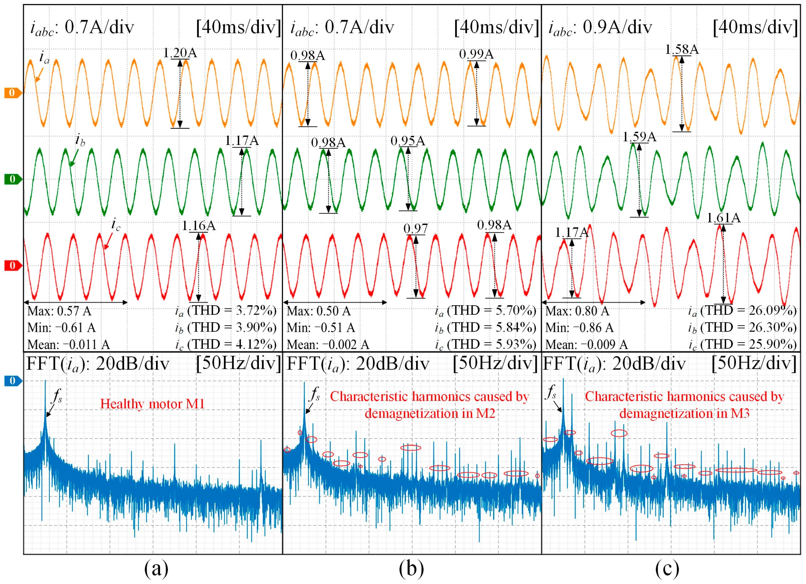
4.1. FFT Analysis of Stator Current After Demagnetization

When local demagnetization occurs in PMSMs, characteristic harmonic components emerge in the stator three-phase current, which can be expressed as
f f = f s 1 ± g p   , g = 1 , 2 , 3 , .
where ff and fs represent the characteristic harmonic and fundamental frequency components of the stator current, respectively, and g denotes the positive integer.
The characteristic frequency described in (15) is either absent or exhibits minimal amplitude in the stator current of a healthy motor. Therefore, appropriate signal processing techniques can be employed to extract this frequency component for demagnetization diagnosis. Figure 4 illustrates the experimental waveforms and spectrum of three-phase currents. As shown in Figure 4a, the three-phase stator current waveform of the healthy motor M1 exhibits negligible amplitude imbalance, with its spectrum primarily consisting of the fundamental frequency fs. In contrast, when the rotor permanent magnet experiences localized demagnetization, the characteristic frequency ff becomes evident in the stator current spectra of the demagnetized motors M2 and M3, resulting in visibly unbalanced waveforms, as shown in Figure 4b,c. Moreover, as the degree of demagnetization increases, both the amplitude and total harmonic distortion (THD) of the characteristic harmonics ff in the stator current rise significantly.

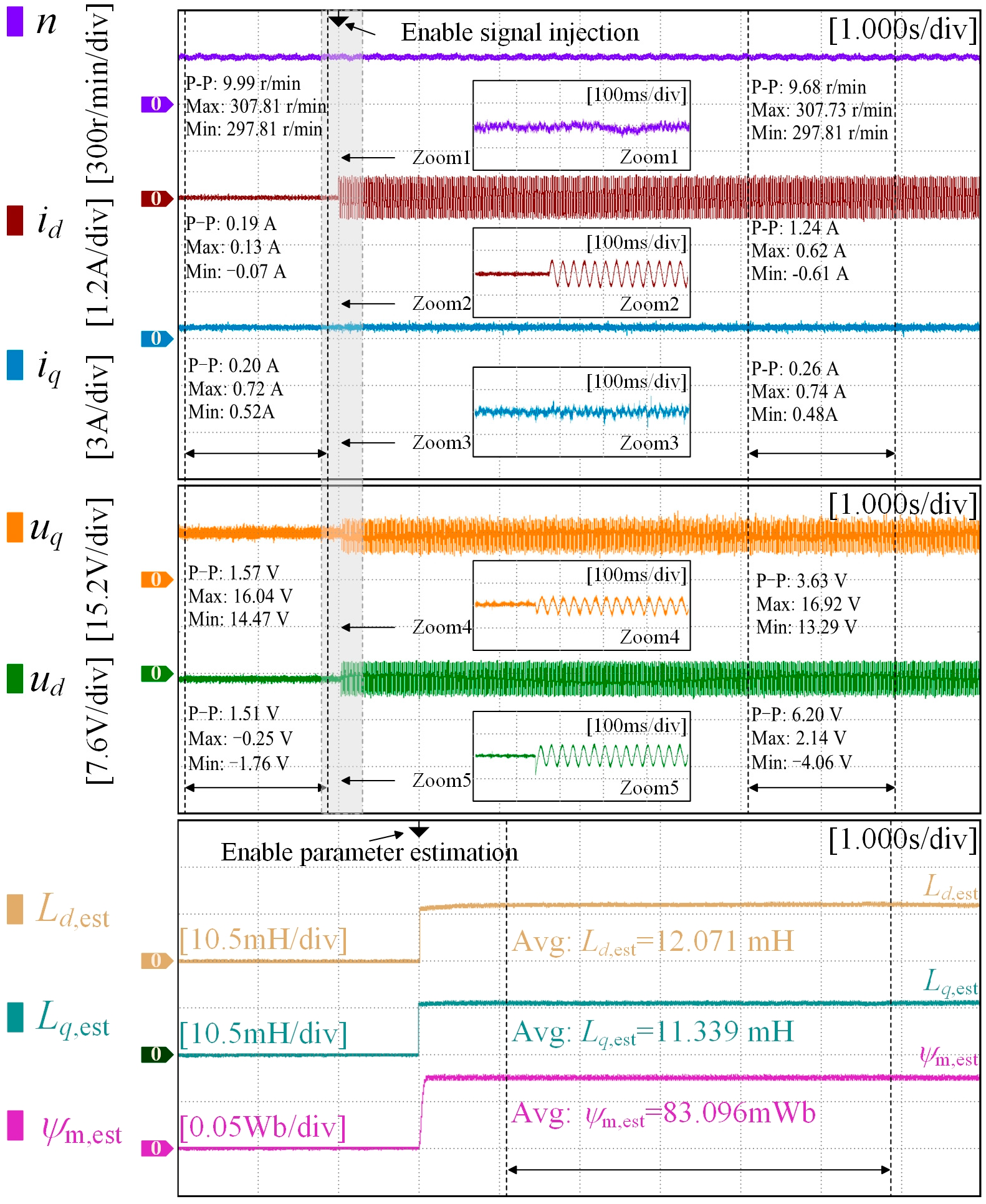
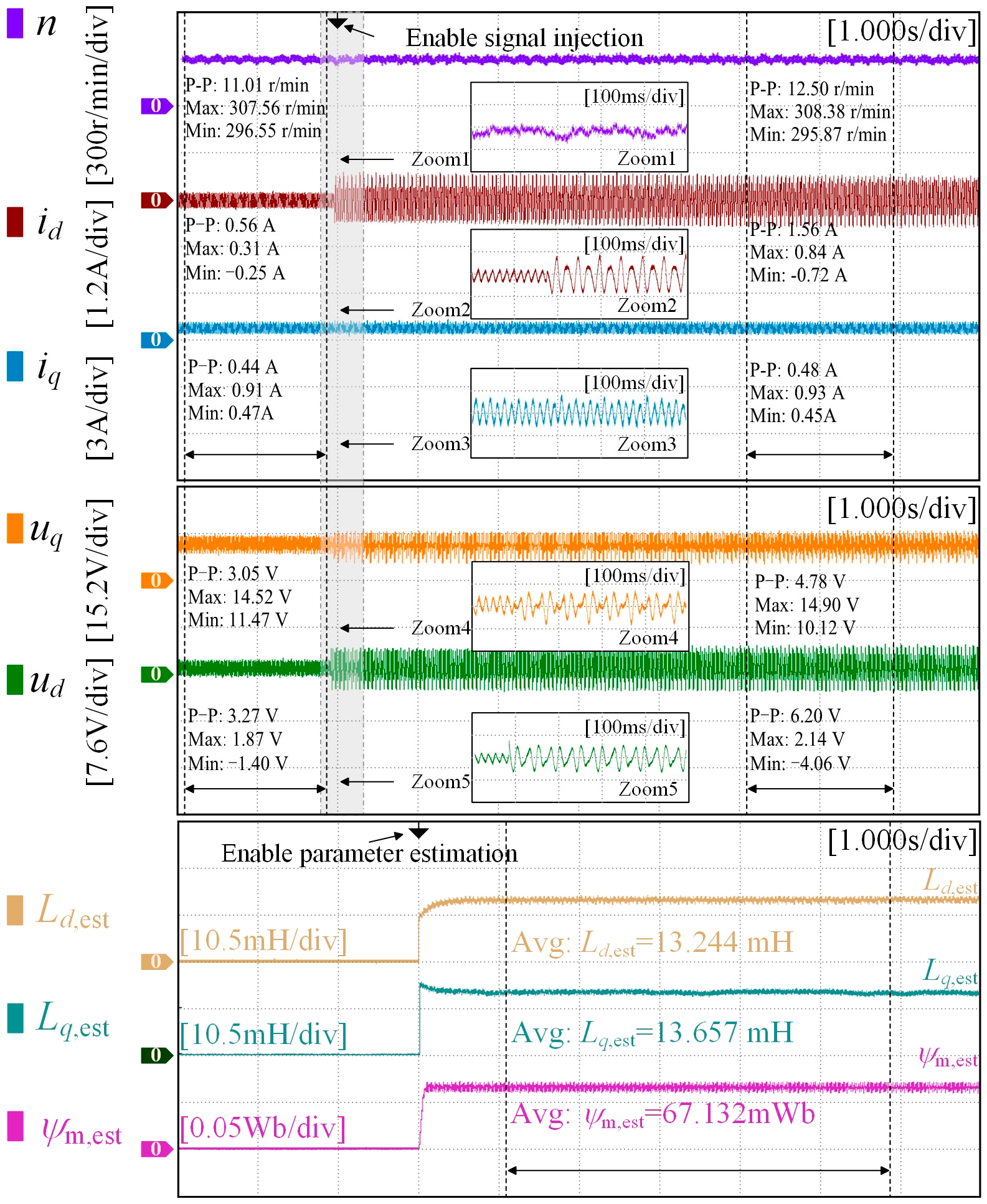
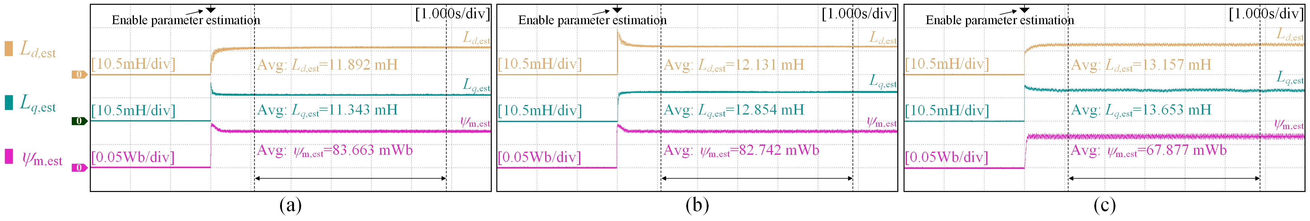
4.2. Experimental Results of Proposed Fault Diagnosis Method

The motor speed is set to 300 r/min and the load torque is maintained at 0.3 N·m. At 2 s, a sinusoidal signal with an amplitude of 0.75 A and a frequency of 40 Hz is injected, and the parameter estimation algorithm is activated at 3 s. The experimental results are shown in Figure 5, Figure 6 and Figure 7. These figures indicate that prior to the injection of the sinusoidal signal, the speed and the dq-axis currents of M2 exhibited minimal fluctuation due to the relatively minor fault condition of M2. However, as the demagnetization severity increased, compared to the healthy Motor M1, the speed and dq-axis current fluctuations of Motor M3 increased by 1.02 r/min, 0.37 A, and 0.24 A, respectively. Therefore, it is necessary to promptly implement a rotor permanent magnet demagnetization diagnosis scheme to prevent further deterioration of the demagnetization fault.
To further quantify the performance of the proposed fault diagnosis scheme, the estimation error and estimation accuracy are defined as
ε 1 = τ est τ τ × 100 % ε 2 = 100 % ε 1
where ε1 and ε2 are the parameter estimation error and estimation accuracy, respectively, and τest and τ are the estimated parameters and actual measurement parameters of the motor, respectively.
Figure 5 illustrates the experimental results of the proposed demagnetization diagnosis algorithm applied to the healthy motor M1. As can be seen from Figure 5, the dq-axis inductance and permanent magnet flux linkage values estimated using the proposed method are obtained as 12.071 mH, 11.339 mH, and 83.096 mWb, respectively. Based on Equation (16) and Table 1, the estimation errors ε1 for the dq-axis inductance and the permanent magnet flux linkage are approximately 4.87%, 4.95%, and 1.43%, respectively, and the corresponding estimation accuracies ε2 are approximately 95.13%, 95.05%, and 98.57%, respectively. Since no demagnetization fault occurred in the motor, its parameters did not significantly deviate from the nominal values, and there was a smooth motor operation with minimal fluctuations in speed and q-axis current.
Furthermore, the performance of the proposed diagnostic method on demagnetization motors M2 and M3 is analyzed, as illustrated in Figure 6 and Figure 7. The estimated dq-axis inductance and permanent magnet flux linkage for demagnetization motor M2 are 12.440 mH, 13.110 mH, and 82.098 mWb, respectively. For demagnetization motor M3, the corresponding estimates are 13.244 mH, 13.657 mH, and 67.132 mWb, respectively. It is evident that the demagnetization effect significantly reduces the flux linkage of the permanent magnet and causes a notable deviation in the dq-axis inductance from its nominal value due to magnetic field distortion. Consequently, the flux parameter can serve as a criterion for demagnetization faults, and the estimation results of the other two algorithms (RLS and DEKF) can interact with each other to enhance the accuracy of the flux estimation. According to Equation (16) and Table 1, the estimated errors ε1 for the dq-axis inductance and permanent magnet flux linkage of demagnetized motor M2 are approximately 4.45%, 4.54%, and 1.79%, with an estimated accuracy ε2 of about 95.55%, 95.46%, and 98.21%, respectively. For motor M3, the estimated errors ε1 are approximately 4.16%, 4.96%, and 3.54%, with an estimated accuracy ε2 of about 95.84%, 95.04%, and 96.46%, respectively. The analysis demonstrates that the proposed algorithm exhibits robust performance on both healthy and demagnetized motors, maintaining an estimated error within 5% and an accuracy above 95%, thereby enabling accurate diagnosis of demagnetization faults and high-precision monitoring of permanent magnets.
Figure 8 shows the experimental results of the proposed method under different load conditions. The experimental results demonstrate that the proposed diagnostic method maintains satisfactory performance when the motor speed is 300 r/min and the load is 1.2 N·m. Based on the calculations from (16) and Table 1, the estimated errors for the dq axis inductance and flux linkage parameters of the healthy motor M1 are 3.21%, 4.92%, and 0.76%, respectively, corresponding to estimated accuracies of 96.79%, 95.08%, and 99.24%. For motor M2, the estimated errors are 1.86%, 2.50%, and 1.03%, with accuracies of 98.14%, 97.50%, and 98.97%, respectively. Motor M3 exhibits estimated errors of 4.80%, 4.98%, and 2.47%, resulting in accuracies of 95.20%, 95.02%, and 97.53%, respectively. These results further substantiate the effectiveness and robustness of the proposed method.

5. Conclusions

An early demagnetization fault warning scheme is proposed in this paper, which can effectively eliminate the estimation error caused by a parameter mismatch and accurately tracks the dynamic changes in a permanent magnet flux linkage. By injecting a sinusoidal current signal into the d-axis of PMSMs, this scheme captures multiple operational states of the motor, thereby addressing the issue of rank deficiency during inductance parameter estimation without significantly impacting the motor’s normal operation. Additionally, a demagnetization fault diagnosis scheme based on parameter estimation is developed. The designed DEKF algorithm enables real-time acquisition of permanent magnet flux linkage parameters, and the RLS identification algorithm facilitates online inductance parameter estimation. The estimated parameters between these two algorithms are interchanged, forming a robust integrated permanent magnet state management system that enhances the accuracy of the flux linkage estimation. Experimental results demonstrate that the proposed scheme exhibits superior parameter estimation performance, with relative errors within 5% and an estimation accuracy above 95%.

Author Contributions

Conceptualization, Z.Z.; data curation, J.W.; formal analysis, J.W.; funding acquisition, Z.Z.; investigation, J.W.; methodology, J.W.; project administration, Z.Z.; resources, Z.Z.; software, Z.Z.; supervision, Z.Z.; validation, J.W.; visualization, J.W.; writing—original draft preparation, J.W.; Writing—review and editing, C.L. All authors have read and agreed to the published version of the manuscript.

Funding

This research was funded by the Natural Science Foundation of Tianjin Municipality under Grant 24JCYBJC00740.

Data Availability Statement

The original contributions presented in the study are included in the article; further inquiries can be directed to the corresponding author.

Conflicts of Interest

The authors declare no conflicts of interest.

References

  1. Faiz, J.; Mazaheri-Tehrani, E. Demagnetization Modeling and Fault Diagnosing Techniques in Permanent Magnet Machines Under Stationary and Nonstationary Conditions: An Overview. IEEE Trans. Ind. Appl. 2016, 53, 2772–2785. [Google Scholar] [CrossRef]
  2. Lv, K.; Wang, D.; Huang, W.; Hu, J. Research on Fault Indicator for Integrated Fault Diagnosis System of PMSM Based on Stator Tooth Flux. IEEE J. Emerg. Sel. Top. Power Electron. 2023, 12, 985–996. [Google Scholar] [CrossRef]
  3. Ai, Q.; Wei, H.; Li, T.; Dou, H.; Zhao, W.; Zhang, Y. Online Demagnetization Fault Recognition for Permanent Magnet Motors Based on the Hall-Effect Analog Sampling. IEEE Trans. Power Electron. 2022, 38, 3600–3611. [Google Scholar] [CrossRef]
  4. Orviz, M.; Laborda, D.F.; Reigosa, D.; Lee, H.J.; Rafaq, M.S.; Lee, S.B.; Briz, F. Demagnetization Detection and Severity Assessment in PMSMs Using Search Coils Exploiting Machine’s Symmetry. IEEE Trans. Ind. Appl. 2023, 59, 4021–4034. [Google Scholar] [CrossRef]
  5. Kang, J.K.; Yoo, D.W.; Hur, J. Application and Verification of Voltage Angle-Based Fault Diagnosis Method in Six-Phase IPMSM. IEEE Trans. Ind. Appl. 2023, 60, 426–438. [Google Scholar] [CrossRef]
  6. Ko, Y.; Lee, Y.; Oh, J.; Park, J.; Chang, H.; Kim, N. Current signature identification and analysis for demagnetization fault diagnosis of permanent magnet synchronous motors. Mech. Syst. Signal Process. 2024, 214, 111377. [Google Scholar] [CrossRef]
  7. Garcia-Calva, T.A.; Gyftakis, K.N.; Skarmoutsos, G.A.; Mueller, M.; Morinigo-Sotelo, D.; Romero-Troncoso, R.D.J. Advanced Signal Processing Techniques for Demagnetization Detection in PM Generators at Variable Speed. IEEE Trans. Ind. Appl. 2023, 60, 174–183. [Google Scholar] [CrossRef]
  8. Zhan, H.; Wu, L.; Lyu, Z.; Du, Y.; Fang, Y. Uneven Demagnetization Fault Diagnosis in Dual Three-Phase Permanent Magnet Machines Based on Electrical Signal Difference. IEEE Trans. Transp. Electrif. 2022, 9, 3026–3039. [Google Scholar] [CrossRef]
  9. Zhu, M.; Hu, W.; Kar, N.C. Acoustic Noise-Based Uniform Permanent-Magnet Demagnetization Detection in SPMSM for High-Performance PMSM Drive. IEEE Trans. Transp. Electrif. 2017, 4, 303–313. [Google Scholar] [CrossRef]
  10. Attestog, S.; Senanayaka, J.S.L.; Khang, H.V.; Robbersmyr, K.G. Robust Active Learning Multiple Fault Diagnosis of PMSM Drives With Sensorless Control Under Dynamic Operations and Imbalanced Datasets. IEEE Trans. Ind. Inform. 2022, 19, 9291–9301. [Google Scholar] [CrossRef]
  11. Zhu, M.; Yang, B.; Hu, W.; Feng, G.; Kar, N.C. Vold–Kalman Filtering Order Tracking Based Rotor Demagnetization Detection in PMSM. IEEE Trans. Ind. Appl. 2019, 55, 5768–5778. [Google Scholar] [CrossRef]
  12. Du, B.; Huang, W.; Cheng, Y.; Chen, J.; Tao, R.; Cui, S. Fault Diagnosis and Separation of PMSM Rotor Faults Using Search Coil Based on MVSA and Random Forests. IEEE Trans. Ind. Electron. 2024, 71, 15089–15099. [Google Scholar] [CrossRef]
  13. Gao, C.; Gao, B.; Xu, X.; Si, J.; Hu, Y. Automatic Demagnetization Fault Location of Direct-Drive Permanent Magnet Synchronous Motor Using Knowledge Graph. IEEE Trans. Instrum. Meas. 2024, 73, 3502312. [Google Scholar] [CrossRef]
  14. Skowron, M.; Orlowska-Kowalska, T.; Kowalski, C.T. Detection of Permanent Magnet Damage of PMSM Drive Based on Direct Analysis of the Stator Phase Currents Using Convolutional Neural Network. IEEE Trans. Ind. Electron. 2022, 69, 13665–13675. [Google Scholar] [CrossRef]
  15. Song, J.; Zhao, J.; Zhang, X.; Dong, F.; Zhao, J.; Xu, L.; Yao, Z. Accurate Demagnetization Faults Detection of Dual-Sided Permanent Magnet Linear Motor Using Enveloping and Time-Domain Energy Analysis. IEEE Trans. Ind. Inform. 2019, 16, 6334–6346. [Google Scholar] [CrossRef]
  16. Zhang, M.; Li, W.; Tang, H. Demagnetization Fault Diagnosis of the Permanent Magnet Motor for Electric Vehicles Based on Temperature Characteristic Quantity. IEEE Trans. Transp. Electrif. 2022, 9, 759–770. [Google Scholar]
  17. Xie, J.; Long, Z.; Zhang, X.; Qin, G.; Huang, F.; Rao, Z. Demagnetization Fault Diagnosis of PMSM Using Custom Phase Space Reconstruction Image. IEEE Trans. Instrum. Meas. 2023, 72, 3526211. [Google Scholar] [CrossRef]
  18. Huang, F.; Zhang, X.; Qin, G.; Xie, J.; Peng, J.; Huang, S.; Long, Z.; Tang, Y. Demagnetization Fault Diagnosis of Permanent Magnet Synchronous Motors Using Magnetic Leakage Signals. IEEE Trans. Ind. Inform. 2022, 19, 6105–6116. [Google Scholar] [CrossRef]
  19. Song, J.; Zhao, J.; Dong, F.; Zhao, J.; Xu, L.; Yao, Z. A New Demagnetization Fault Recognition and Classification Method for DPMSLM. IEEE Trans. Ind. Inform. 2019, 16, 1559–1570. [Google Scholar] [CrossRef]
  20. Zhang, X.; Tang, J.; Qu, Y.; Qin, G.; Guo, L.; Xie, J.; Long, Z. Few-Shot Fault Diagnosis Based on Heterogeneous Information Fusion and Meta Learning. IEEE Sens. J. 2023, 23, 21433–21442. [Google Scholar] [CrossRef]
  21. Zhao, K.; Yin, T.; Zhang, C.; He, J.; Li, X.; Chen, Y.; Zhou, R.; Leng, A. Robust model-free nonsingular terminal sliding mode control for PMSM demagnetization fault. IEEE Access 2019, 7, 15737–15748. [Google Scholar] [CrossRef]
  22. Kang, Y.; Yao, L. Sliding mode observer-based fault diagnosis and continuous control set fault tolerant control for PMSM with demagnetization fault. Measurement 2024, 235, 114867. [Google Scholar] [CrossRef]
  23. Wang, Q.; Wang, G.; Xiong, X.; Li, Q.; Li, B.; Zhang, G.; Chang, J.; Xu, D. Magnetic Flux Linkage Estimation of PMSM Based on Split Step Decoupling Strategy. IEEE Trans. Transp. Electrif. 2024, 11, 3996–4009. [Google Scholar] [CrossRef]
  24. Zhao, J.; Wang, L.; Xu, L.; Dong, F.; Song, J.; Yang, X. Uniform Demagnetization Diagnosis for Permanent-Magnet Synchronous Linear Motor Using a Sliding-Mode Velocity Controller and an ALN-MRAS Flux Observer. IEEE Trans. Ind. Electron. 2021, 69, 890–899. [Google Scholar] [CrossRef]
  25. Wen, D.; Wei, X.; Zhang, W.; Li, S.; Zhang, Y. Improved Supertwisting Nonsingular Fast Terminal Sliding Mode Observer-Based Deadbeat Fault-Tolerant Predictive Control for IPMSM Demagnetization Fault. IEEE Trans. Power Electron. 2024, 39, 13643–13658. [Google Scholar] [CrossRef]
  26. Yin, S.; Li, X.; Gao, J.; Chen, A.; Han, Y. A Novel Demagnetization Fault Diagnosis Scheme for the IPM Motor Without Parameter Estimation. IEEE Trans. Power Electron. 2024, 39, 15468–15473. [Google Scholar] [CrossRef]
  27. Zhao, K.; Leng, A.; Zhou, R.; Dai, W.; Wu, S.; Li, T. Demagnetization fault reconstruction for six-phase permanent magnet synchronous motor by improved super-twisting algorithm-based sliding-mode observer. Measurement 2021, 172, 108905. [Google Scholar] [CrossRef]
Figure 1. Block diagram of the demagnetization fault diagnosis based on DEKF.
Wevj 16 00112 g001
Figure 2. Control block diagram of the proposed demagnetization fault diagnosis method.
Wevj 16 00112 g002
Figure 3. Experimental platform.
Wevj 16 00112 g003
Figure 4. Experimental waveforms of the stator current and its spectrum. (a) M1. (b) M2. (c) M3.
Wevj 16 00112 g004
Figure 5. Experimental results of the proposed diagnosis method in M1.
Wevj 16 00112 g005
Figure 6. Experimental results of the proposed diagnosis method in M2.
Wevj 16 00112 g006
Figure 7. Experimental results of the proposed diagnosis method in M3.
Wevj 16 00112 g007
Figure 8. Experimental results of the proposed diagnosis method at 1.2 N·m (a) M1 (b) M2, (c) M3.
Wevj 16 00112 g008
Table 1. Parameters of the tested prototype.
ParametersSymbolsM1M2M3
Number of pole-pairsp555
Rated currentIN3.7 A3.7 A3.7 A
Permanent magnet fluxψm0.0843 Wb0.0836 Wb0.0696 Wb
Stator resistanceRs1.203 Ω1.226 Ω1.275 Ω
d-axis inductanceLd11.51 mH11.91 mH13.82 mH
q-axis inductanceLq11.93 mH12.54 mH14.37 mH
Disclaimer/Publisher’s Note: The statements, opinions and data contained in all publications are solely those of the individual author(s) and contributor(s) and not of MDPI and/or the editor(s). MDPI and/or the editor(s) disclaim responsibility for any injury to people or property resulting from any ideas, methods, instructions or products referred to in the content.

