Article

A Block Controller with Integral Super-Twisting Algorithm for the Path Following of a Self-Driving Electric Vehicle Considering Actuator Dynamics

by
Luis Arturo Torres-Romero
and
Luis Enrique González-Jiménez
*
Department of Electronics Systems and Computing, Instituto Tecnológico y de Estudios Superiores de Occidente (ITESO), Tlaquepaque 45604, Jalisco, Mexico
*
Author to whom correspondence should be addressed.
World Electr. Veh. J. 2025, 16(12), 643; https://doi.org/10.3390/wevj16120643
Submission received: 25 October 2025 / Revised: 23 November 2025 / Accepted: 24 November 2025 / Published: 25 November 2025

Abstract

This research presents the design of a robust nonlinear controller for the lateral dynamics of a self-driving car. It is based on the block control and super-twisting sliding mode control techniques in order to effectively mitigate the uncertainties and disturbances of the vehicle. The dynamic model of the system is composed of the standard bicycle dynamic model (not kinematic) for the vehicle and the dynamics of a BLDC motor connected to a steering rack system as the steering actuator. Moreover, the control scheme considers an inner loop for controlling the actuator position based on the field-oriented control (FOC) and PID control approaches. The controller’s overall performance is validated through its application to a mathematical model of a brushless direct current (BLDC) motor, acting as the actuator, plus the steering rack dynamics and the lateral dynamic model of the vehicle. Measurements of voltages and currents are taken in both the abc and dq reference frames, the latter being commonly used in the field-oriented control (FOC) technique. Additionally, the system’s performance is evaluated in terms of trajectory tracking, orientation, and lateral deviation from the lane center.

1. Introduction

The automotive industry is rapidly advancing toward vehicle electrification and autonomous mobility, driven by goals such as the Paris agreement’s mandate, which seeks to reduce emissions due to the fossil fuels used by car engines. Autonomous mobility can offer benefits in this regard; as an example, autonomous systems can find the most efficient routes and drive with the most efficient speeds and accelerations to reduce energy consumption, in addition to the safety improvements that non-human driving can bring. There are many approaches to tackle the complexity of an automotive self-driving system, however, most of them follow a similar generic structure for the system architecture based on layers, as shown in Figure 1 and Figure 2. Specifically, Figure 1 depicts the standard control architecture for a steer-by-wire system with two control stages: a lateral controller, designed to enable the vehicle to follow a desired path, and an actuator controller (in this case, a BLDC motor), designed to generate the specific control inputs for the actuator. Among these layers, we can find the route planning layer, the behavioral layer, the motion planning layer, and the local feedback control layer [1,2]. The design of the latter is the objective of this work. The blue box with the label “Lateral Controller” is where our contribution is applied. It belongs to the local feedback control layer, which is in charge of controlling the steering of the vehicle. The upper layers define a route, often given in the form of waypoints that commonly consist of the desired speed and the X,Y reference coordinates that the vehicle must follow. Diverse works have been developed for the described problem. For example, ref. [3] intends to create a controller free of the physical model of the vehicle and uses conventional sliding mode control (SMC); it proposes to adapt the gains of the control at runtime. Ref. [4] implements a model predictive control that combines fuzzy logic and neural networks that adapt to different longitudinal speeds. However, its mathematical validity is still pending and under investigation. Refs. [5,6,7,8,9,10] uses model predictive control (MPC) to solve the path following problem by considering the kinematic or dynamic lateral model of the vehicle and implementing a cost function. Refs. [11,12] uses reinforced learning to tackle the path following problem. Ref. [13] applies state-feedback control to an autonomous tractor with a trailer. It proposes a control algorithm and a path planning algorithm. Ref. [14] uses a kinematic model to compare several of the most common controllers for path following such as “follow the carrot”, “pure pursuit”, “vector pursuit”, the “Stanley method”, the “MIT method”, and “CF pursuit”. Ref. [15] implements feed-forward control but using the planar two-track vehicle model. Ref. [16] implements a linear quadratic regulator (LQR) control technique, which is an optimization technique to solve the path following problem, where controller parameters are designed by minimizing a cost function. In [17], a control scheme is presented to solve the path following problem in three dimensions for a marine vehicle. Other works as [18] are based on the super-twisting algorithm (STA), which is a second-order sliding mode controller that presents several advantages over conventional SMC such as the reduction of the chattering effect, and the robustness against matched disturbances [19,20]. Moreover, ref. [21] applies two STA controllers in parallel: one for lateral error dynamics and one for yaw error dynamics. Ref. [22] apply the STA using a sliding surface formed by a combination of lateral speed and orientation errors. Both of them applied an additional method to find the parameters using neural networks or optimization methods. Ref. [23] used the STA in combination with an adaptive preview model and an additional low-pass filter to eliminate the chattering effect. However, they did not take into account the effects of actuator dynamics and used very simplified models for the vehicle. In this work, a combination of block control and an integral STA is proposed for the path following problem in an electric autonomous vehicle. The combination of these control algorithms aims to increase the robustness of the global control scheme as this is a well-known feature of sliding mode control techniques. Furthermore, the actuator dynamics, which is composed of a BLDC motor coupled to the steering system of the vehicle, is controlled by a PID control based on the field-oriented control (FOC) scheme. This allows us to separate the actuator controller design from the design of the lateral controller of the vehicle. On the other hand, usually the parameters of electric motors are unknown or difficult to obtain, which makes the PID controller an excellent addition as its design and tuning do not require the model of the controlled system.

2. Path Following for a Self-Driving Automotive Vehicle

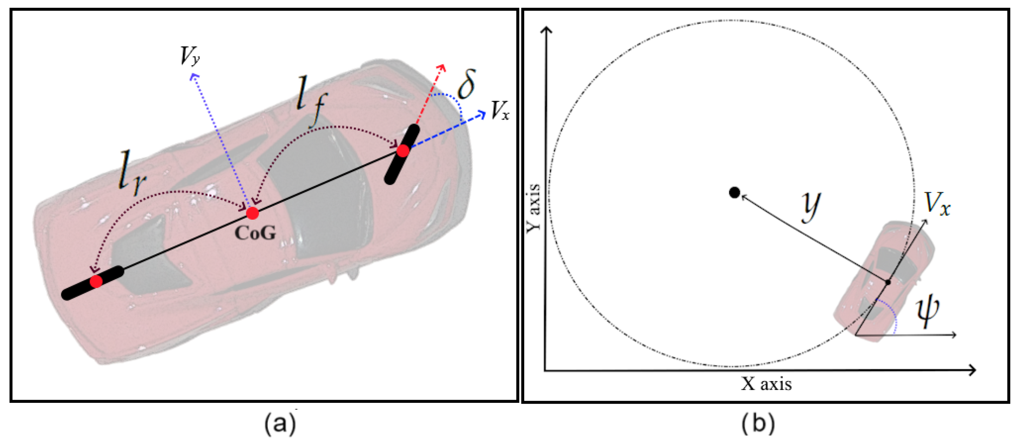
As explained briefly in Section 1, self-driving vehicles implement the basic sections depicted in Figure 2 where the route planning layer is in charge of defining the route to follow from a starting point to a destination through the streets of a city. Once the route has been decided, the behavioral layer will be responsible for reacting to the external stimulus and will be aware of the surroundings during movement along the established route. This layer decides the execution of primitive actions such as changing lane, stopping to wait for a pedestrian, reducing the vehicle’s speed, performing a maneuver to overtake another vehicle, etc. Then, these actions are translated by the motion planning layer, which defines the physical trajectory that the vehicle must track but expressed in accordance with the vehicle’s variables. This translated reference is received by the local feedback control layer, which generates the control input signals for the vehicle received by its actuators. The dynamical model used for the controller design corresponds to the standard bicycle model, where the two front and rear tires are simplified as if they were only one, resembling a bicycle. This is depicted in Figure 3 where the variables and parameters of the bicycle model are shown. In the figure, l f and l r correspond to the distances from the center of gravity (CoG) to the front and rear axles, respectively; δ is the orientation angle of the front wheel with respect to the fixed frame body; V x and V y represent the longitudinal and lateral velocities of the vehicle; y is the distance measured from the center of gravity (CoG) of the vehicle to the center of the circle that describes the trajectory of the vehicle; and ψ is the orientation angle of the vehicle with respect to the inertial frame defined by the X-axis and Y-axis.
A dynamical model for the vehicle can be obtained as [24]
y ¨ = 2 C α f α f + 2 C α r α r m + g sin ( ϕ ) ψ ˙ V x ψ ¨ = 2 l f C α f α f 2 l r C α r α r I z α f = δ θ v f α r = θ v r θ v f = tan 1 y ˙ + l f ψ ˙ V x θ v r = tan 1 y ˙ l f ψ ˙ V x
and
X ˙ Y ˙ = cos ( ψ ) sin ( ψ ) sin ( ψ ) cos ( ψ ) V x V y
where X and Y represent the coordinates of the CoG of the vehicle with respect to the inertial frame; α f and α r are the lateral slip angle for the front and rear tires; C α f , C α r are the lateral stiffness coefficients for the front and rear tires, respectively; l f and l r are the distances measured from the CoG of the vehicle to the front and rear tire axes; m is the vehicle’s mass; g is the gravity constant; ϕ is the road bank or the superelevation of the road; and I z is the moment of inertia of the vehicle with respect to the vehicle’s Z-axis. It is worth noting that this model avoids the use of the popular small-angle simplification tan θ v f θ v f .

3. Overall Control Scheme

Figure 2 shows the basic architecture of a self-driving software stack. The route planning layer is responsible for determining the optimal path from the current location to the desired destination. This path is defined by taking into account several conditions such as road type, distance, legal restrictions, traffic conditions, etc. Once the path is defined, it is passed to the next layer, the behavioral layer, which decides how the vehicle should act according to different situations that the vehicle might encounter during the trip, like the presence of a red traffic light, of pedestrians, or of cyclists, decide if overtake or not, change a lane, etc. Based on the outcomes of this layer, the motion planning layer translate these decisions to specific movements that the vehicle must perform; this involves creating a path that the vehicle must follow, ensuring it is free of obstacles, and ensuring that this movement will be comfortable for passengers. Now, this path is taken by the local feedback control layer, which is what this paper is about, and physically performs this predetermined trajectory, which is expressed in terms of the states of the vehicle. The task addressed by the proposed control scheme is complex considering the parameters (mass, inertia, friction, etc.) and nonlinearity of a standard automotive vehicle. The next subsection describes in detail the control methodology applied to synthesize the control law for the lateral dynamics of the vehicle.

3.1. Lateral Sliding Mode Controller

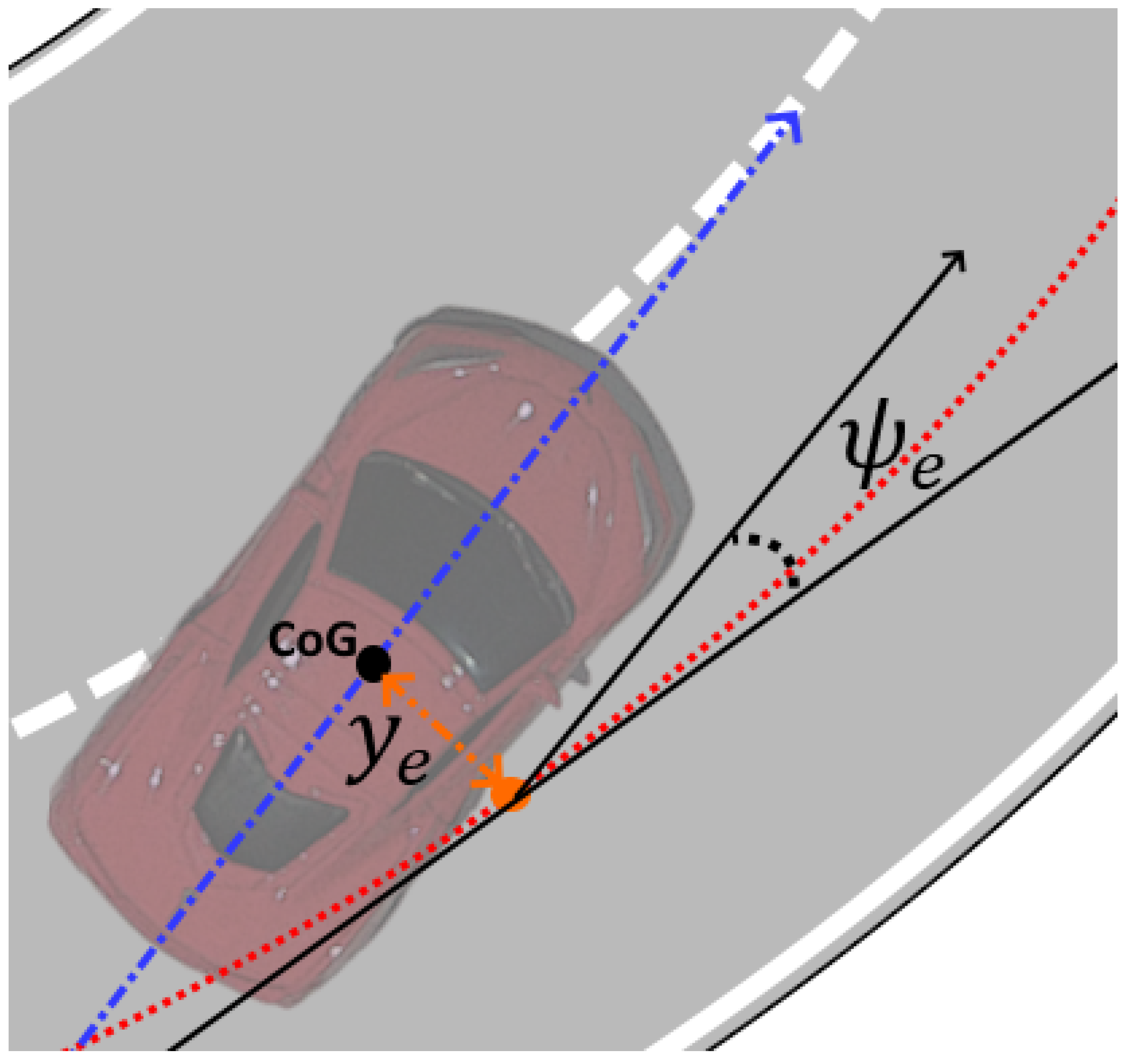
This controller receives a reference for the position x r e f , y r e f and orientation ψ r e f of the vehicle and, along with the current state of the vehicle, calculates the lateral displacement error y e and the orientation error ψ e as depicted in Figure 4. The lateral displacement error y e is computed based on an orthogonal line to the tangent line of the current position of the vehicle.
Then, by defining auxiliary error variables as:
y 1 ( t ) = y e ψ e , y 2 ( t ) = y ˙ e ψ ˙ e ,
we can define the dynamics of (3), by means of (1), of the form
y ˙ 1 = y 2 y ˙ 2 = A 1 y 1 + A 2 y 2 + B δ + L + λ ( y 1 , y 2 , t )
where
A 1 = 0 2 C α f + 2 C α r m 0 2 C α f l f 2 C α r l r I z , A 2 = 2 C α f + 2 C α r m V x 2 C α f l f + 2 C α r l r m V x 2 C α f l f 2 C α r l r I z V x 2 C α f l f 2 + 2 C α r l r 2 I z V x , B = 2 C α f m 2 C α f l f I z , L = l 1 l 2 ,
where l 1 = ( 2 C α f l f 2 C α r l r m V x V x ) ψ ˙ d e s + g sin ( ϕ ) and l 2 = ( 2 C α f l f 2 + 2 C α r l r 2 I z V x ) ψ ˙ d e s . The term λ ( y 1 , y 2 , t ) R 2 × 1 corresponds to the disturbances generated by uncertainties in the vehicle’s parameters and sensors measurements. This term is assumed to be unknown, but is bounded as
| λ ( y 1 , y 2 , t ) | < Λ .
Now, the following theorem establishes the proposed controller.
Theorem 1. 
Any solution of the closed-loop system formed by the controller
δ = δ 0 + δ 1
where
e = k 1 y 1 y 2 , v ˙ 0 = k v 0 sign ( e ) δ 0 = B + ( A 1 y 1 + ( k 1 I 2 + A 2 ) y 2 + L k u 0 | e | 1 / 2 sign ( e ) + v 0 ) ,
σ = e + z , v ˙ 1 = k v 1 sign ( σ ) , δ 1 = B + ( k u 1 | σ | 1 / 2 sign ( σ ) + v 1 ) , z ˙ = A 1 y 1 + ( k 1 I 2 + A 2 ) y 2 + L + B δ 0
and the system (4) is ultimately bounded if conditions (6), z ( 0 ) = e ( 0 ) and
k 1 > 0
k u 0 > 0 , k v 0 > 0
k u 1 > 2 Λ , k v 1 > k u 1 5 Λ k u 1 + 4 Λ 2 2 ( k u 1 2 Λ )
are satisfied.
Proof. 
Let us define a sliding surface σ as in (9), then, its dynamics can be obtained using (4), (8) and (9) as
σ ˙ = B B + ( k u 1 | σ | 1 / 2 sign ( σ ) + v 1 ) λ ( t , y 1 , y 2 ) v ˙ 1 = k v 1 sign ( σ ) .
The objective is to demonstrate that, in a closed loop, the sliding surface converges to zero, and, consequently, the disturbance term λ ( t , y 1 , y 2 ) is rejected. Now, we propose a candidate Lyapunov function V 1 = Γ 1 P 1 Γ 1 T with
Γ 1 = | σ | 1 / 2 sign ( σ ) v 1 , P 1 = 1 2 4 k u 1 + k v 1 2 k v 1 k v 1 2 ;
its derivative results from the form V ˙ 1 = | σ | 1 / 2 ( Γ 1 Q 1 Γ 1 T + λ ( t , y 1 , y 2 ) q Γ 1 T ) with
Q 1 = k u 1 2 2 k u 1 + k v 1 2 k v 1 k v 1 1 , q = 2 k u 1 + k v 1 2 2 k v 1 2
as | B B + | = 1 . Then, by means of (6), V ˙ 1 yields
V ˙ 1 k u 1 2 | σ | 1 / 2 Γ 1 2 k v 1 + k u 1 2 ( 4 k v 1 k u 1 + k u 1 ) k u 1 2 Λ k u 1 2 Λ 1 Γ 1 T
which is negative-definite under conditions (12). Hence, σ and σ ˙ converge to 0 in finite time [25], which generates the equality B δ 1 = λ ( t , y 1 , y 2 ) . It is worth noting that, as z ( 0 ) = e ( 0 ) σ ( 0 ) = 0 , and the sliding motion occurs from the initial instance.
After this, and using (8), the dynamics of the error variable e are reduced to
e ˙ = B B + ( k u 0 | e | 1 / 2 sign ( e ) + v 0 ) v ˙ 0 = k v 0 sign ( e ) .
Again, proposing the candidate Lyapunov function V 0 = Γ 0 P 0 Γ 0 T with
Γ 0 = | e | 1 / 2 sign ( e ) v 0 , P 0 = 1 2 4 k u 0 + k v 0 2 k v 0 k v 0 2 ;
its derivative results from the form V ˙ 0 = | e | 1 / 2 ( Γ 0 Q 0 Γ 0 T ) with
Q 0 = k u 0 2 2 k u 0 + k v 0 2 k v 0 k v 0 1 ,
as | B B + | = 1 . If conditions (11) are satisfied, then, e 0 and e ˙ 0 in finite time, and the dynamics of y 1 yields
y ˙ 1 = k 1 y 1 .
Finally, using (10), the origin of the system y 1 is globally asymptotically stable. Therefore, the lateral displacement error y e and the orientation error converge to 0 in finite time; i.e., the objective of the lateral controller is fulfilled. □

3.2. Actuator Controller

Commonly, the actuator in steer-by-wire systems is a BLDC motor coupled to a steering rack system. The input of the BLDC motor is a three-phase voltage V a b c that generates a desired angular position δ r e f of the steering system, as depicted in Figure 2.

3.2.1. BLDC Motor Dynamics

The dynamic model of the actuator can be represented as [26,27]
d d t i a i b i c = 1 L s M s 0 0 0 1 L s M s 0 0 0 1 L s M s V a V b V c R s 0 0 0 R s 0 0 0 R s i a i b i c e a e b e c
where R s is the stator resistance, assumed to be the same for the three phases a , b , c . L s is the inductance in phases a , b , c . M s is the mutual inductance between phases a b , c a , c b , and we assume that all have the same value. [ e a e b e c ] T = e a b c represents the back electromotive force (EMF). [ i a i b i c ] T = i a b c are the currents of the three phases in the stator. [ V a V b V c ] T = V a b c are the voltages in the three phases of the stator; below, we define e a b c
e a = λ e ω m f a   where   f a = f ( θ e ) , e b = λ e ω m f b   where   f b = f ( θ e 2 π 3 ) , e c = λ e ω m f c   where   f c = f ( θ e + 2 π 3 ) .
The torque equation is defined as
T e = ( e a i a + e b i b + e c i c ) / ω m = ( λ e f a i a + λ e f b i b + λ e f c i c )
where λ e is the Back EMF constant in v/rad/s. θ e is the electrical rotor angle. ω m is the mechanical angular velocity of the rotor shaft in rad/s, and it is related to the electrical speed as ω m = 2 P ω e . f a , f b , f c are functions that have the same shape as e a , e b , e c with a maximum magnitude of ±1; the three functions are the same but displaced as 120°. The equation of motion, solved for T l —that is, the torque load which is applied to the gearbox of the steering system—is
T l = T e b ω m J ω ˙ m .
The electrical and mechanical angular speeds and positions are related by
ω e = θ ˙ e = P 2 ω m ,
θ m = 2 P θ e
where P is the number of poles; in our case, it is equal to 8.

3.2.2. Steering Rack System Model

The term T l in (24) represents the torque transmitted to the steering rack system, whose dynamical model can be defined as [28]
J s δ ¨ + b s δ ˙ = N m T l + τ a + τ f
δ = θ m N m
where τ a = N l F z V x sin δ is the self-aligning torque, τ f = N l F z tanh δ ˙ ε is the friction force of the tire over the ground, F z = m g 2 is the normal force acting on the tire, assuming the bicycle model ϵ > 0 is an approximation of the slope for the friction torque, N m and N l are transmission ratios, J s , and b s are the equivalent moment of inertia and damping coefficient of the steering system, respectively.

3.2.3. Position Control Algorithm

To facilitate the controller design procedure of a BLDC motor, a transformation is applied from a b c to d q coordinates of the currents and voltages of the motor. This is achieved by means of the Park–Clarke transform [29,30] and its inverse, which are defined as
P C T = 2 3 cos θ cos θ 2 π 3 cos θ + 2 π 3 sin θ sin θ 2 π 3 sin θ + 2 π 3 1 2 1 2 1 2 , P C T 1 = 2 3 cos θ sin θ 1 2 cos θ 2 π 3 sin θ 2 π 3 1 2 cos θ + 2 π 3 sin θ + 2 π 3 1 2 .
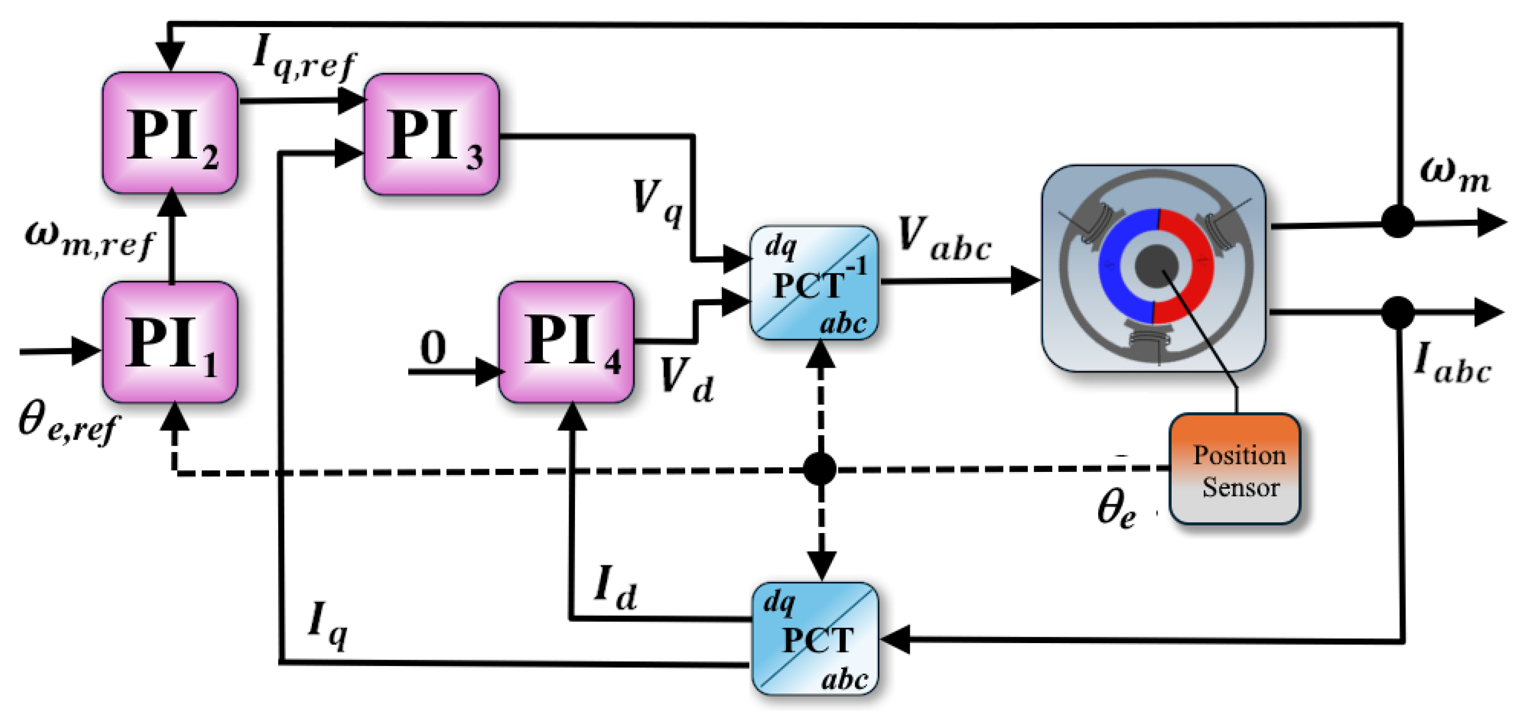
The actuator control strategy is depicted in Figure 5, which corresponds to the field-oriented control (FOC) approach based on PI (Proportional-Integral) controllers expressed in d q coordinates.
Hence, the general control objective is to force θ e to follow θ e , r e f by means of V a b c . From (27) and (25), we obtain θ e , r e f = δ r e f N m P 2 , and the error variables for the PI controllers can be defined as
e P I 1 = θ e , r e f θ e , e P I 2 = ω m , r e f ω m , e P I 3 = I q , r e f I q , e P I 4 = I d .
The execution of the actuator controller can be described as follows: first, the P I 1 controller computes e P I 1 and generates ω m , r e f ; then, the P I 2 controller uses ω m , r e f to compute e P I 2 and generates I q , r e f ; after that, the P I 3 controller uses I q , r e f to compute e P I 3 and generates the V q input voltage; finally, the P I 4 controller generates the V d input voltage by means of the I d current as its desired value is 0. The resulting V d q voltages are transformed into V a b c using the Park–Clarke transform. The control gains for the four PI controllers were, firstly, obtained using the automatic tuner tool of Simulink and, then, by applying manual fine-tuning to improve the transient of the closed-loop system’s response in terms of settling time and overshoot. This is important as the internal closed-loop system defined by the actuator’s controller must have a lower constant time than the outer control loop defined by the vehicle’s controller. This impacts also the required computational capacities of the ECU (Electronic Control Unit) where the embedded implementation of the control scheme will be deployed.

4. Simulation Results

Before proceeding with the simulation results, the authors want to mention that the readers can download the SIMULINK model corresponding to this work at [31] or [32]. It is a work in progress, but currently includes longitudinal dynamics, tire dynamics, lateral dynamics, and BLDC/DC motors as steering and traction actuators. Moreover, it contains the implementation of a variety of control algorithms for lateral dynamics. Table 1 shows the vehicle parameters used in the simulation experiments, which were obtained from [24,33]. On the other hand, Table 2 shows the controller gains, which were defined according to the stability conditions defined in Theorem 1.
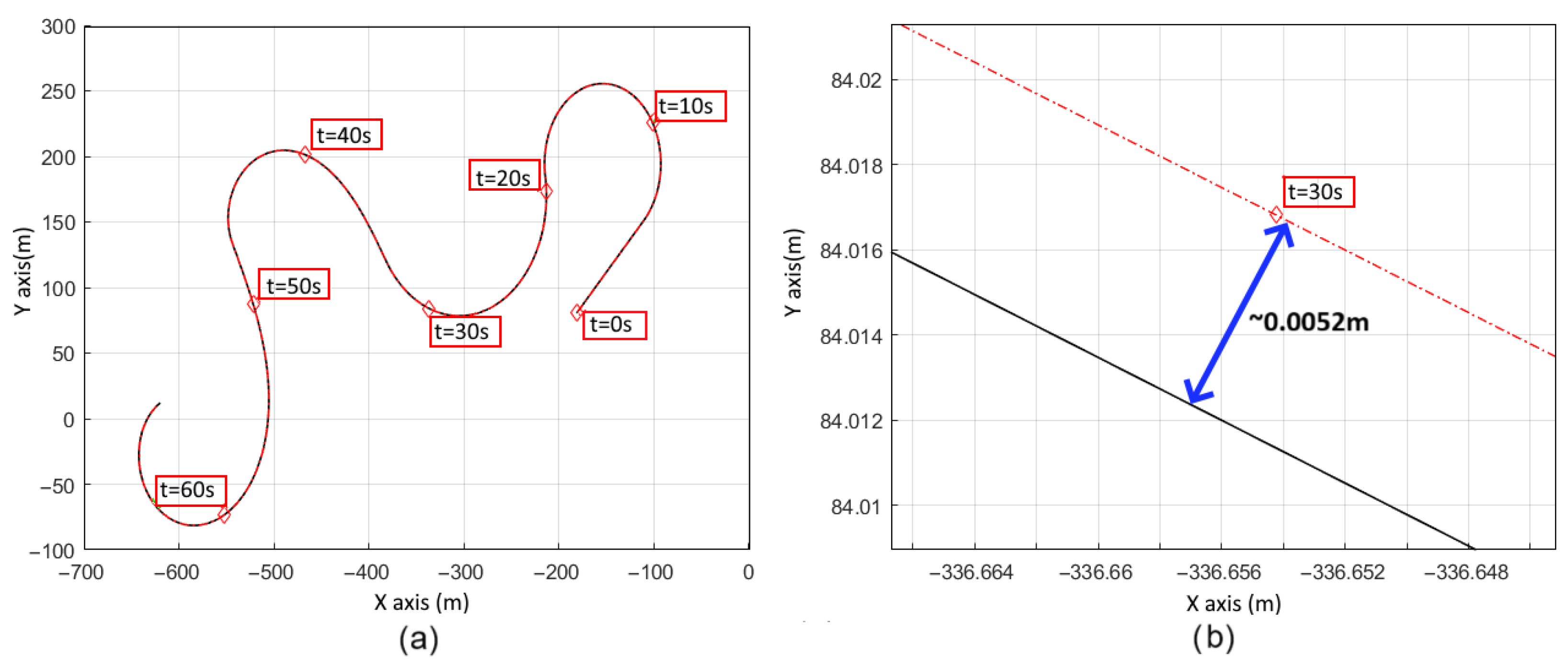
Figure 6 shows the trajectory tracking performance for both controllers. During the reported experiments, it is assumed that V x = 18 m/s = 65 km/h. This is a constraint on the dynamics of the vehicle, as it is not possible to follow a prescribed path with constant longitudinal velocity in a real scenario. However, 65 km/h is an acceptable nominal velocity for an autonomous electric vehicle which allows us to validate the effectiveness of the proposed control scheme.
Furthermore, a time variable road bank ϕ (or the superelevation of the road) was defined in the form
ϕ = tan 1 V x 2 127 R
where R is the radius of the curvature of the desired trajectory. Notice that this expression is a simplification of a real road bank which is usually more complex and takes into consideration many other elements. However, this version of the road bank allows us to recreate a more realistic version of the dynamics of an autonomous vehicle. The left part of the image depicts global trajectory tracking and the right part shows a close-up of a segment of the trajectory at t = 30 s. It can be seen that the control objective was achieved and, in addition, Table 3 shows that the average lateral displacement error is ≈0.0221 m, which is 10 times smaller than the resulting average error of [34].
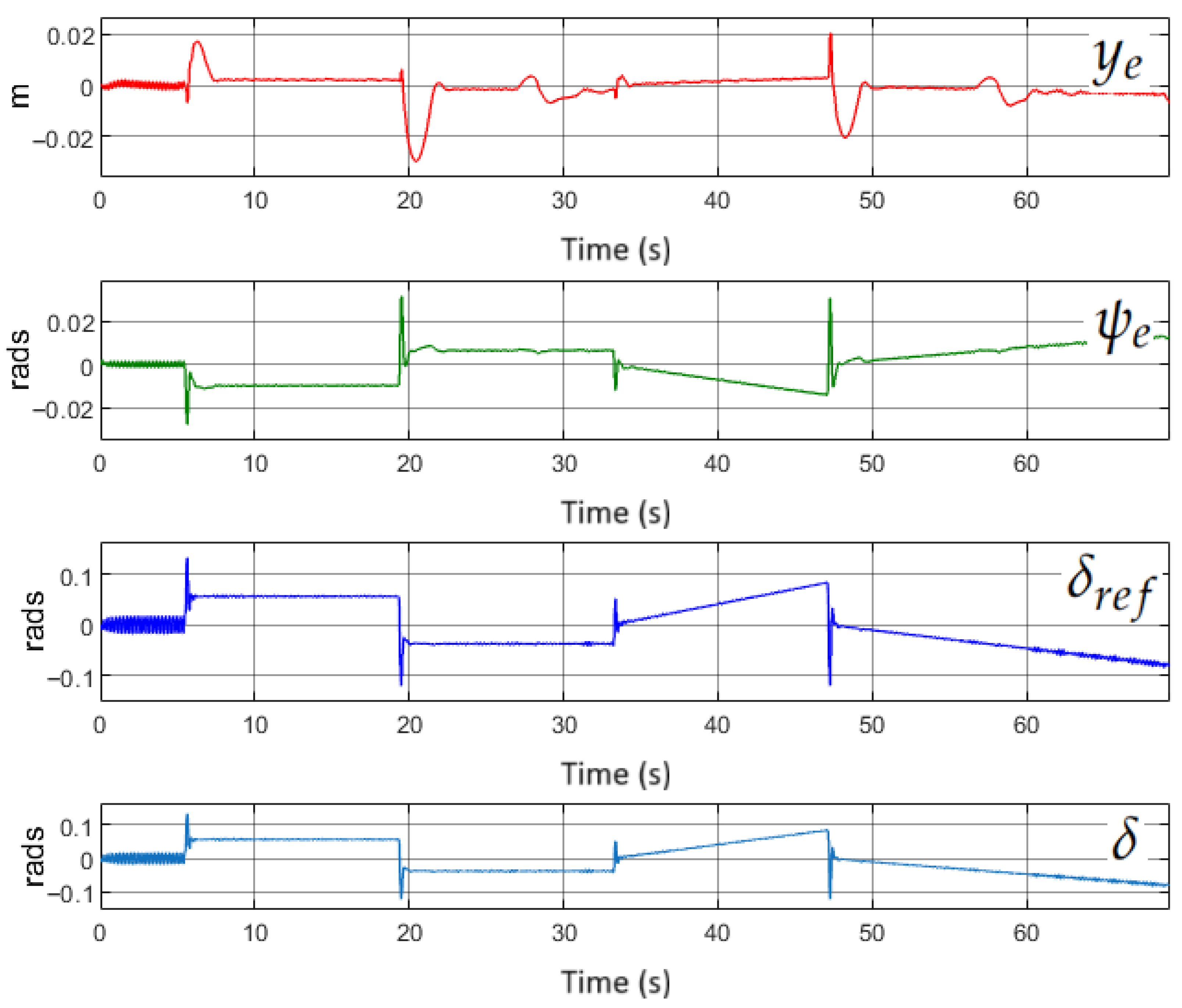
Figure 7 shows the lateral displacement error y e and orientation error ψ e during the experiment, which confirm the good performance of the controller. Moreover, the steering angle δ and its reference δ r e f are also shown. Compared to [34], the control input is no longer characterized by the presence of chattering and, in addition, it is bounded by 0.12 rad which represents a steering angle that is feasible to implement in a real steer-by-wire system for autonomous driving.
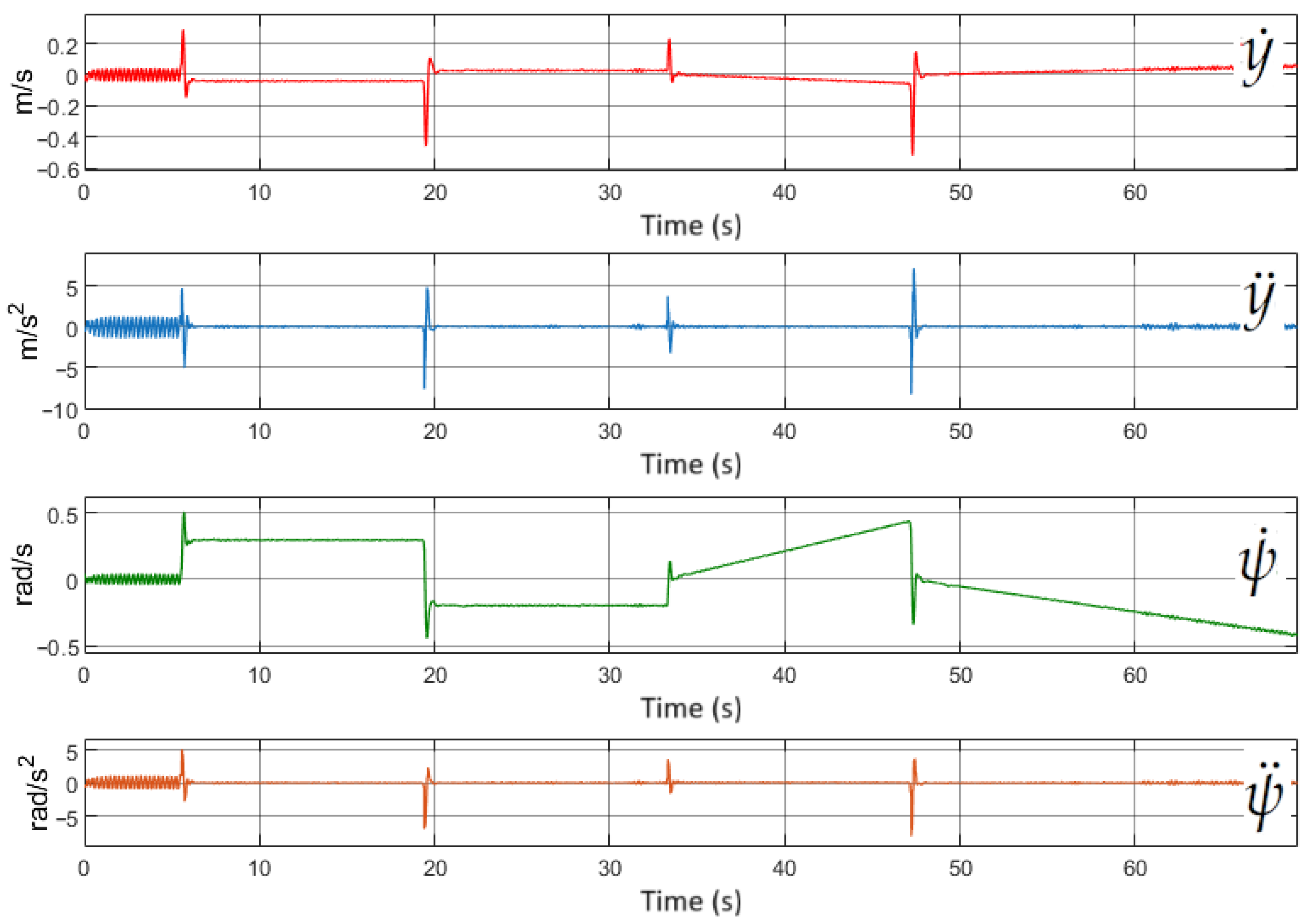
The lateral speed y ˙ , lateral acceleration y ¨ , orientation velocity ψ ˙ , and acceleration ψ ¨ of the vehicle are shown in Figure 8. All these variables remain within the expected values for a real automotive vehicle.
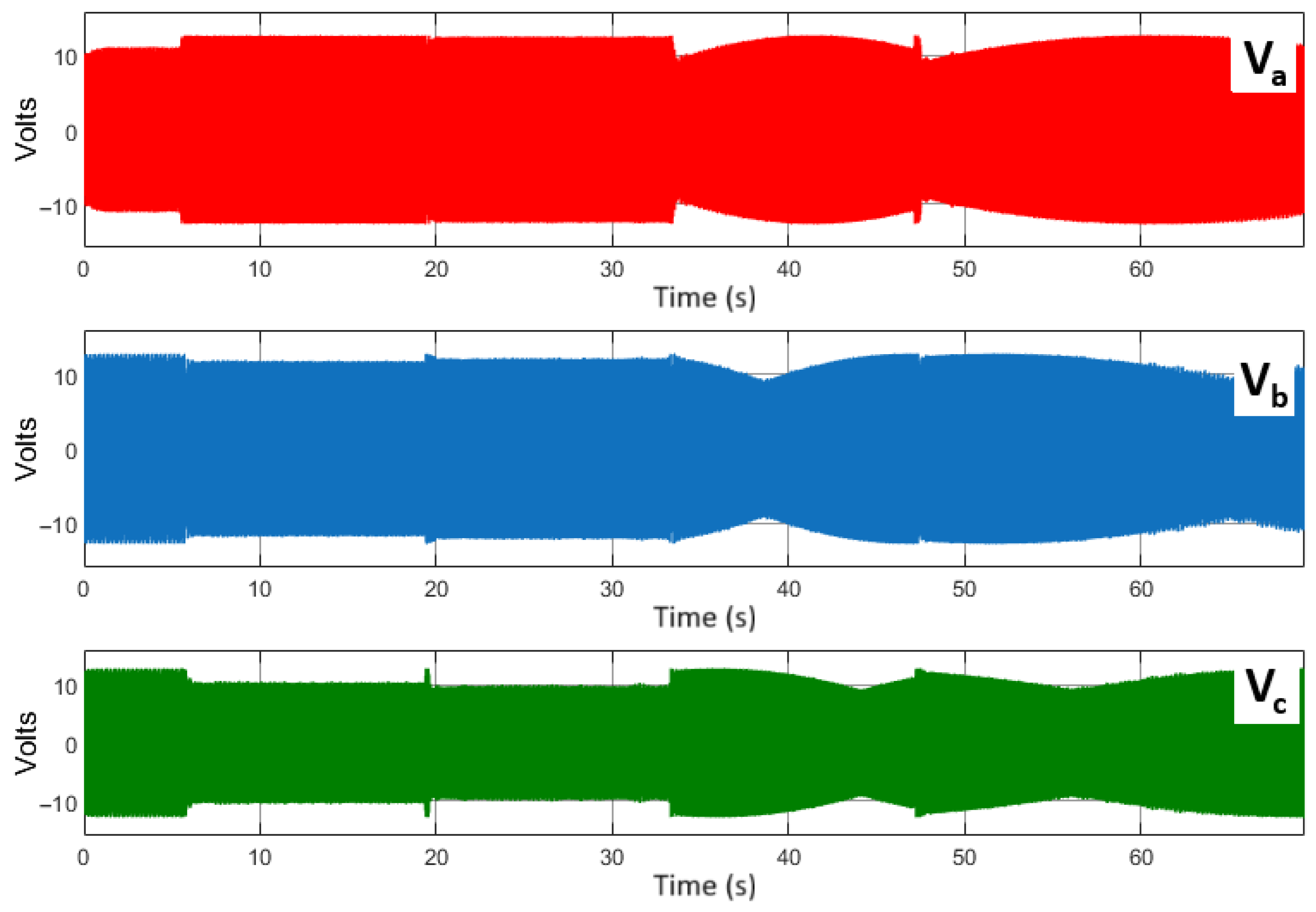
On the other hand, Figure 9 presents the error variables of the four internal PI controllers, which are part of the field-oriented control system for the steering actuator. It can be observed that the error variables of the PI controllers for the actuator are characterized by high peaks and, in the case of the PI 4 , a constant high-frequency component. These undesirable effects are considerably attenuated by the low-pass filter nature of the electric motor and due to the saturation of its driver, which forbids the application of voltages greater than 24 V to the motor. This can be appreciated in Figure 10, where the generated voltages are within the normal range of the considered electric motor. In addition to that, the figure demonstrates the effectiveness of the controller and how it responds to abrupt changes in δ r e f .
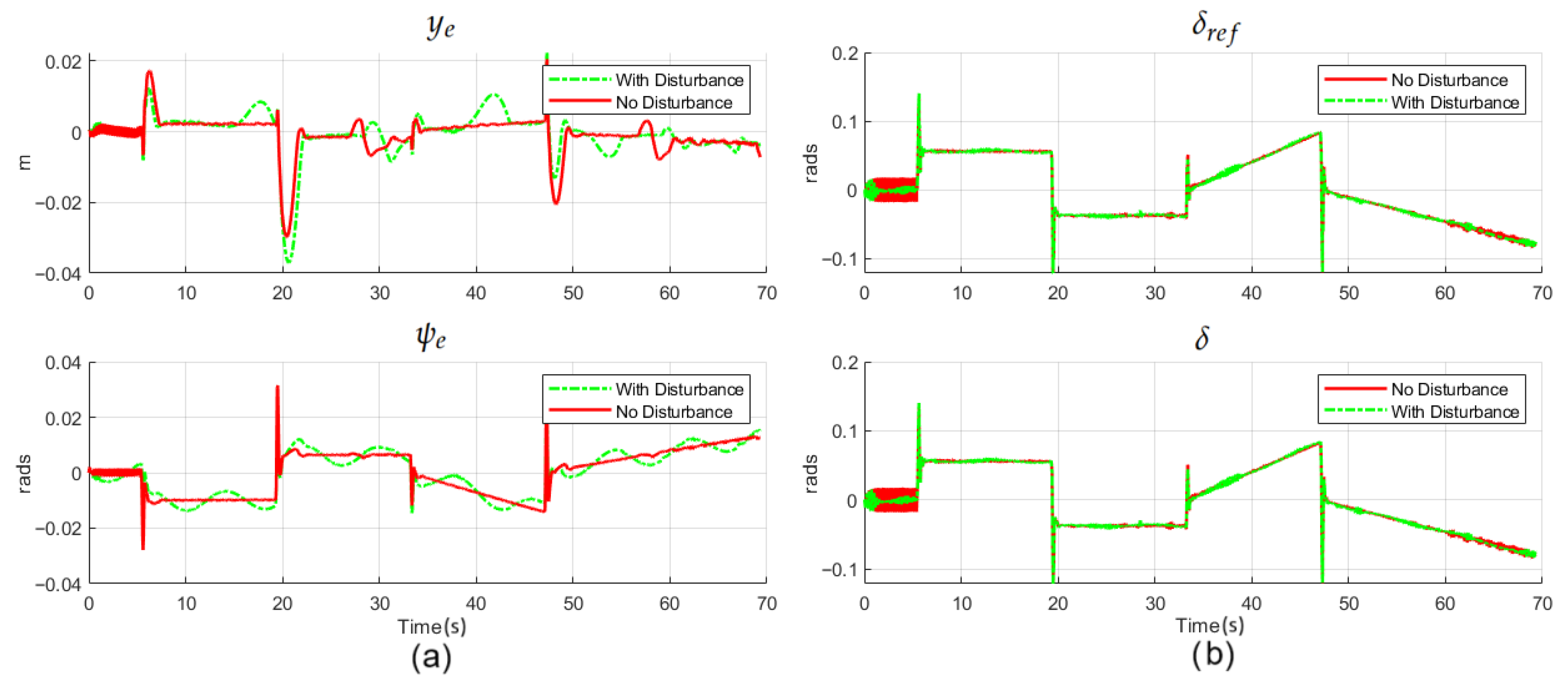
In order to test the robustness of the proposed controller, a second experiment was conducted where a disturbance term λ ( t ) was added to the system dynamics, which were defined as
λ = 3 5 sin ( π 4 t ) π 60 sin ( π 8 t ) .
It is worth noting that although this disturbance term was theoretically designed to test the robustness of the global controller, it represents perturbations on the lateral acceleration and in the yaw angle acceleration of the vehicle. Indirectly, this defines the effect of an external lateral force and a yaw torque on the vehicle dynamics.
The simulation results are shown in Figure 11: in (a) the error variables y e and ψ e are presented for both experiments—considering the disturbance term and neglecting it—and in (b) the desired δ r e f and the actual steering angle δ are displayed. It can be noted that the performance of the controller is evidently affected by the disturbances, but not significantly as neither the magnitude nor the bandwidth of the variable errors were increased. This conclusion applies to the dynamics of the error systems and the input control signals of the overall control scheme. This strongly suggests that the capabilities of the proposed control scheme are robust. Finally, a comparison between the performance of the control scheme designed in this work and the one proposed in [34] is shown in Figure 12. It can be seen that the magnitude of the control signal for the lateral controller is lower in the case of the controller proposed in this work. Moreover, the high-frequency components in the control inputs and in the error variables are considerably reduced, which directly impacts the efficiency of the overall control scheme and the life cycle of the vehicle actuators.

5. Discussion

The simulation results have demonstrated the effectiveness of the proposed control scheme in terms of path following, robustness against matched perturbations, relative smoothness of the control signals, and implementation feasibility. For instance, in comparison with the results reported in [5], the proposed controller reduced the lateral displacement error during the simulations by 50%. On the other hand, related works, such as [3,4,6,7,8,9,10], develop their respective control algorithms based on the kinematic or lateral dynamical model of the vehicle, which is inconvenient when a real-world implementation of the controller is necessary. Moreover, these works do not consider the dynamics of the actuators (usually electric motors) which modifies the dynamics of the overall vehicle. By discarding this factor, the probability of obtaining the same performance on a real vehicle are drastically reduced. Finally, the improvement against [34] is evident as the chattering effect was significantly reduced and the resulting smoothed control signals are more suitable for real-world implementation without compromising the integrity of the actuators.

6. Conclusions and Future Work

In this work, a control scheme for the path following of an electric autonomous vehicle was developed and implemented in a simulation environment. It is based on the combination of three control techniques: the block control, integral sliding modes, and the super-twisting algorithm. The dynamical model of the electric vehicle is composed of the lateral dynamics of the vehicle, the electrical actuator dynamics, and the steering rack dynamics. It is assumed that the longitudinal velocity of the vehicle is constant, but the road bank depends on the curvature radius of the path to follow. In addition, a disturbance term was added in the second simulation experiment to validate the robustness of the proposed control scheme. The proposed control scheme integrates the control signal’s smoothness that is achieved by the super-twisting algorithm with the block control technique, which makes it possible to control variables the dynamics of which are not directly affected by the control inputs. According to the simulation results presented, the performance of the proposed control scheme is satisfactory as the path following of a desired trajectory, which is composed of a series of waypoints in the X-Y plane, was achieved. Moreover, the control inputs, which correspond to the steering angle of the steering rack system and the input voltages of its actuator, are consistent in terms of magnitude and bandwidth, in line with the standard demands of the actuators of a real autonomous automotive vehicle. On the other hand, compared to the results obtained in [34], the performance of the proposed controller exhibits a significant reduction in chattering and high-frequency components in the control signals. Also, as shown in Table 3, the average lateral displacement error is 10 times smaller than the resulting average error in [34]. Furthermore, the magnitudes of the control inputs, steering angle, and input voltages of the actuator feature are also lower. On top of that, this closed-loop performance was obtained despite the presence of disturbances in the form of a time variant force and a torque applied directly to the vehicle’s lateral displacement and orientation dynamics. The next steps being considered for this work are the implementation of the proposed control algorithm in a car simulator such as CarSim [35] or CARLA [36] to validate its performance in a more realistic simulation environment. Also, further developments may include the integration of longitudinal dynamics to the vehicle model and its corresponding traction controller. This would improve the usability of the model for path following and stability evaluation. On the other hand, future implementation of the controller on a real prototype of an electric autonomous vehicle is also being considered, where the integration of signal conditioning stages for sensor noise reduction will be crucial.

Author Contributions

Conceptualization, L.E.G.-J. and L.A.T.-R.; methodology, L.E.G.-J. and L.A.T.-R.; software, L.A.T.-R.; validation, L.E.G.-J. and L.A.T.-R.; formal analysis, L.E.G.-J. and L.A.T.-R.; investigation, L.E.G.-J. and L.A.T.-R.; resources, L.E.G.-J. and L.A.T.-R.; data curation, L.E.G.-J. and L.A.T.-R.; writing—original draft preparation, L.E.G.-J. and L.A.T.-R.; writing—review and editing, L.E.G.-J. and L.A.T.-R.; visualization, L.A.T.-R. and L.E.G.-J.; supervision, L.E.G.-J.; project administration, L.E.G.-J. and L.A.T.-R. All authors have read and agreed to the published version of the manuscript.

Funding

The authors would like to thank the Mexican Secretary of Science, Humanities, Technology and Innovation (Secihti) by the scholarships 172488 and 453637.

Institutional Review Board Statement

Not applicable.

Informed Consent Statement

Not applicable.

Data Availability Statement

The dynamical model of the vehicle and the proposed controller can be found in [31].

Conflicts of Interest

The authors declare no conflicts of interest.

Abbreviations

The following abbreviations are used in this manuscript:
BLDCBrushless Direct Current motor
FOCField-Oriented Control
SVPWMSpace Vector Pulse Width Modulation
PIProportional-Integral Control
MPCModel Predictive Control
IMUInertial Measurement Unit
LIDARLight Detection and Ranging
SMCSliding Mode Control
ISMIntegral Sliding Mode
STASuper-Twisting Algorithm
STSMCSuper-Twisting Sliding Mode Control
SAESociety of Automotive Engineers
HOSMHigh-Order Sliding Modes
LKASLane Keeping Assist System
LDALane Departure Avoidance
ELKSEmergency Lane Keeping System

References

  1. Paden, B.; Cap, M.; Yong, S.; Yershov, D.; Frazzoli, E.; Vázquez, D. A Survey of Motion Planning and Control Techniques for Self-Driving Urban Vehicles. IEEE Trans. Intell. Veh. 2016, 1, 33–35. [Google Scholar] [CrossRef]
  2. Velasco-Hernandez, G.; Yeong, D.J.; Barry, J.; Walsh, J. Autonomous Driving Architectures, Perception and Data Fusion: A Review. In Proceedings of the 2020 IEEE 16th International Conference on Intelligent Computer Communication and Processing (ICCP), Cluj-Napoca, Romania, 3–5 September 2020; pp. 315–321. [Google Scholar] [CrossRef]
  3. Oh, K.; Seo, J. Development of a Sliding-Mode-Control-Based Path-Tracking Algorithm with Model-Free Adaptive Feedback Action for Autonomous Vehicles. Sensors 2023, 23, 405. [Google Scholar] [CrossRef] [PubMed]
  4. Yuan, X.; Huang, G.; Shi, K. Improved Adaptive Path Following Control System for Autonomous Vehicle in Different Velocities. IEEE Trans. Intel. Transp. Syst. 2020, 21, 3247–3256. [Google Scholar] [CrossRef]
  5. Liang, J.; Tian, Q.; Feng, J.; Pi, D.; Yin, G. A polytopic model-based robust predictive control scheme for path tracking of autonomous vehicles. IEEE Trans. Intell. Veh. 2023, 9, 3928–3939. [Google Scholar] [CrossRef]
  6. Vu, T.M.; Moezzi, R.; Cyrus, J.; Hlava, J. Model Predictive Control for Autonomous Driving Vehicles. Electronics 2021, 10, 2593. [Google Scholar] [CrossRef]
  7. Xu, Z.; He, L.; Huang, C.; Zheng, X.; Li, S.; Shi, Q. A model-tuned predictive sliding control approach for steering angle following of full self-driving vehicles. Proc. Inst. Mech. Eng. Part C J. Mech. Eng. Sci. 2024, 238, 7399–7409. [Google Scholar] [CrossRef]
  8. Fernandez, B.; Herrera, P.; Cerrada, J. A Simplified Optimal Path Following Controller for an Agricultural Skid-Steering Robot. IEEE Access 2019, 7, 95932–95940. [Google Scholar] [CrossRef]
  9. Guo, N.; Zhang, X.; Zou, Y.; Lenzo, B.; Zhang, T. A Computationally Efficient Path-Following Control Strategy of Autonomous Electric Vehicles With Yaw Motion Stabilization. IEEE Trans. Transp. Electrif. 2020, 6, 2. [Google Scholar] [CrossRef]
  10. Ritschel, R.; Schrödel, F.; Hädrich, J.; Jäkel, J. Nonlinear Model Predictive Path-Following Control for Highly Automated Driving. IFAC-PapersOnLine 2019, 52, 350–355. [Google Scholar] [CrossRef]
  11. Ultsch, J.; Mirwald, J.; Brembeck, J.; De Castro, R. Reinforcement Learning-based Path Following Control for a Vehicle with Variable Delay in the Drivetrain. In Proceedings of the 2020 IEEE Intelligent Vehicles Symposium (IV), Las Vegas, NV, USA, 19–30 October 2020; pp. 532–539. [Google Scholar]
  12. Woo, J.; Yu, C.; Kim, N. Deep reinforcement learning-based controller for path following of an unmanned surface vehicle. Ocean Eng. 2019, 183, 155–166. [Google Scholar] [CrossRef]
  13. Ljungqvist, O.; Evestedt, N.; Axehill, D.; Cirillo, M.; Pettersson, H. A path planning and path-following control framework for a general 2-trailer with a car-like tractor. J. Field Robot. 2019, 36, 1345–1377. [Google Scholar] [CrossRef]
  14. Bacha, S.; Ayad, M.Y.; Aboubou, A.; Bahri, M.; Becherif, M. Modeling and Control Techniques for Autonomous Electric and Hybrid Vehicles Path following. In Proceedings of the 2017 5th International Conference on Electrical Engineering-Boumerdes (ICEE-B), Boumerdes, Algeria, 29–31 October 2017; pp. 1–12. [Google Scholar]
  15. De Castro, R.; Tanelli, M.; Esteves, A.R.; Savaresi, S.M. Minimum-Time Path-Following for Highly Redundant Electric Vehicles. IEEE Trans. Control Syst. Technol. 2016, 24, 2. [Google Scholar] [CrossRef]
  16. Hossain, T.; Habibullah, H.; Islam, R. Steering and Speed Control System Design for Autonomous Vehicles by Developing an Optimal Hybrid Controller to Track Reference Trajectory. Machines 2022, 10, 420. [Google Scholar] [CrossRef]
  17. Maurya, P.; Morishita, H.M.; Pascoal, A.; Aguiar, A.P. A Path-Following Controller for Marine Vehicles Using a Two-Scale Inner-Outer Loop Approach. Sensors 2022, 22, 4293. [Google Scholar] [CrossRef]
  18. Dika, M.; Owayjan, M.; Achkar, R. Steering Control of Self-Driving Car Using Super-Twisting Sliding Mode Control. In Proceedings of the 2023 Fifth International Conference on Advances in Computational Tools for Engineering Applications (ACTEA), Zouk Mosbeh, Lebanon, 5–7 July 2023; pp. 190–196. [Google Scholar] [CrossRef]
  19. Utkin, V.; Guldner, J.; Shi, J. Sliding Mode Control in Electro-Mechanical Systems; CRC Press: Boca Raton, FL, USA, 2009. [Google Scholar]
  20. Shtessel, Y.; Edwards, C.; Fridman, L.; Levant, A. Sliding Mode Control and Observation; Springer: New York, NY, USA, 2014; pp. 155–158. [Google Scholar]
  21. Takele, T.; Terefe, T.; Ma, S.S. Super Twisting Sliding Mode Controller for Trajectory Tracking Control of Autonomous Ground Vehicle System. In Proceedings of the International Conference on Advances of Science and Technology, Bahir Dar, Ethiopia, 4–6 November 2022; Springer Nature: Cham, Switzerland, 2022; pp. 272–289. [Google Scholar]
  22. Hakjoo, K.I.M.; Seok-Cheol, K.E.E. Neural Network Approach Super-Twisting Sliding Mode Control for Path-Tracking of Autonomous Vehicles. Electronics 2023, 12, 3635. [Google Scholar]
  23. Bei, S.; Hu, H.; Li, B.; Tian, J.; Tang, H.; Quan, Z.; Zhu, Y. Research on the Trajectory Tracking of Adaptive Second-Order Sliding Mode Control Based on Super-Twisting. World Electr. Veh. J. 2022, 13, 141. [Google Scholar] [CrossRef]
  24. Rajamani, R. Vehicle Dynamics and Control; Springer Science & Business Media: New York, NY, USA, 2011. [Google Scholar]
  25. Moreno, J.A.; Fridman, L. A survey on High-Order Sliding-Mode control design using Lyapunov functions. IFAC-PapersOnLine 2023, 56, 25–36. [Google Scholar] [CrossRef]
  26. Mondal, S.; Mitra, A.; Chattopadhyay, M. Mathematical modeling and simulation of brushless DC motor with ideal back emf for a precision speed control. In Proceedings of the 2015 IEEE International Conference on Electrical, Computer and Communication Technologies (ICECCT), Coimbatore, India, 5–7 March 2015; pp. 1–5. [Google Scholar]
  27. Pillay, P.; Krishnan, R. Modeling, simulation, and analysis of permanent-magnet motor drives. IEEE Trans. Ind. Appl. 1989, 25, 265–273. [Google Scholar] [CrossRef]
  28. Wu, X.; Xu, X.; Chen, L.; Cai, Y. Robust Control of Electric Power Steering System Based on Aligning Torque Model. In Proceedings of the 2024 IEEE 22nd International Conference on Industrial Informatics (INDIN), Beijing, China, 18–20 August 2024; pp. 1–6. [Google Scholar] [CrossRef]
  29. Bose, B.K. Modern Power Electronics & AC Drives; Prentice Hall: Upper Saddle River, NJ, USA, 2002. [Google Scholar]
  30. Bolton, W.C. Mechatronics: Electronic Control Systems in Mechanical and Electrical Engineering; Pearson Education: London, UK, 2018. [Google Scholar]
  31. Vehicle Dynamics and Controller Simulink Model. Available online: https://github.com/L-Arturo-Torres-Romero/VehicleModel/tree/master/VehicleModel (accessed on 24 October 2023).
  32. Torres-Romero, L. L-Arturo-Torres-Romero/VehicleModel: Conventional SMC for Lateral Dynamic 2. Zenodo 2024. Available online: https://zenodo.org/records/1054731 (accessed on 10 June 2025).
  33. Five Slippery Cars Enter a Wind Tunnel; One Slinks out a Winner. Available online: https://www.tesla.com/sites/default/files/blog_attachments/the-slipperiest-car-on-the-road.pdf (accessed on 10 June 2025).
  34. Torres-Romero, L.A.; Ruiz-Cruz, R.; González-Jiménez, L.E. Path-Following Sliding Mode Controller for an Electric Vehicle Considering Actuator Dynamics. Machines 2024, 12, 219. [Google Scholar] [CrossRef]
  35. CarSim: Mechanical Simulation. Available online: https://www.carsim.com/ (accessed on 27 November 2023).
  36. CARLA: Open-Source Simulator for Autonomous Driving Research. Available online: http://carla.org (accessed on 10 November 2023).
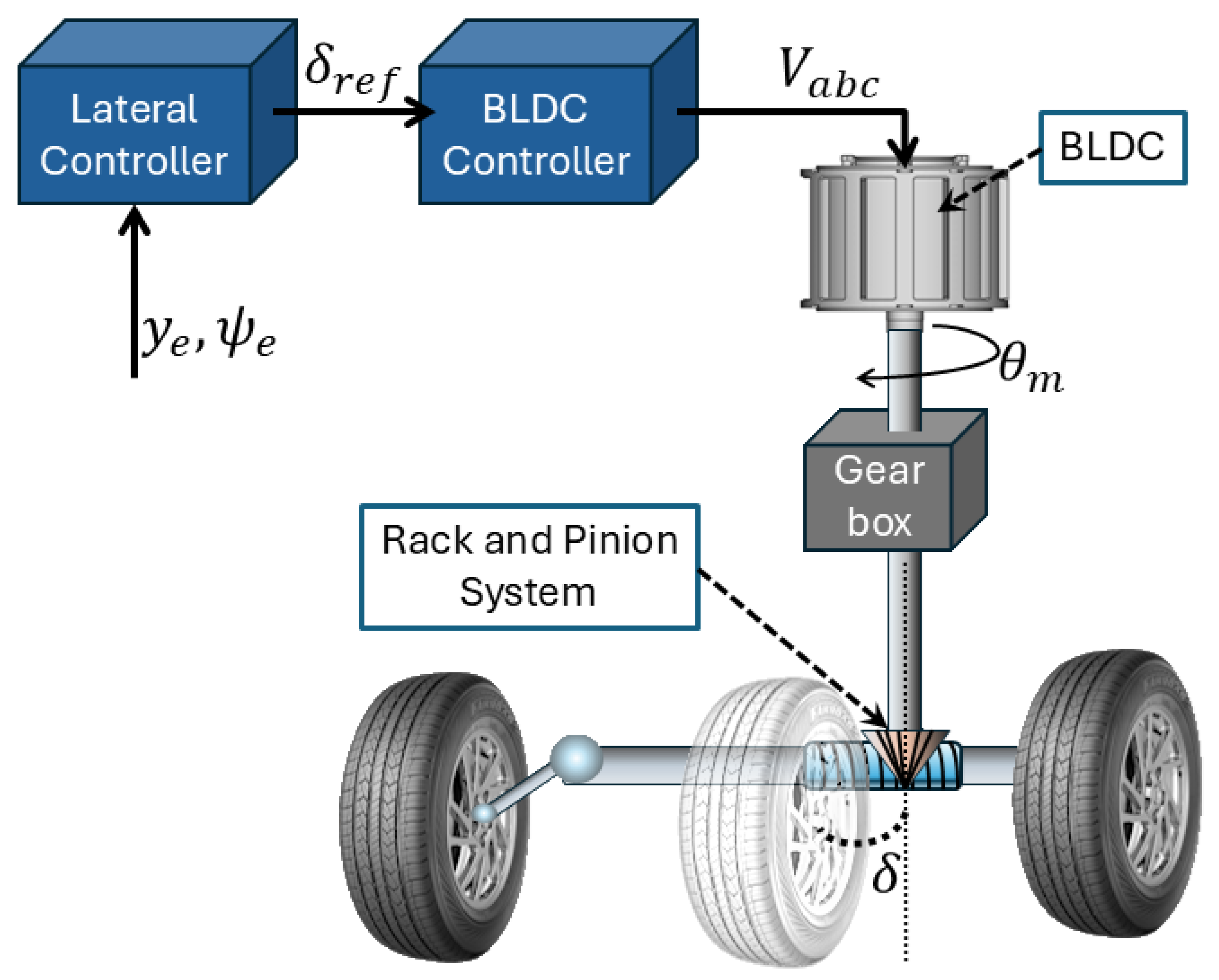
Figure 1. Overall control architecture for path following with different levels of autonomy. The translucent tire represents the equivalent front axle of the vehicle in the bicycle model simplification.
Wevj 16 00643 g001
Figure 2. General control scheme for the local feedback control layer and an overview of the software’s stack layer system for a self-driving vehicle.
Wevj 16 00643 g002
Figure 3. (a) Bicycle Model. (b) Components of the lateral dynamics.
Wevj 16 00643 g003
Figure 4. The lateral displacement error y e and orientation error ψ e of the vehicle with respect to the followed path (lane). The blue-dashed arrow represents the current orientation of the vehicle. The red-dotted line represents the followed path. The orange-dotted line represents the lateral error defined as the shortest distance between the CoG of the vehicle and the desired path.
Wevj 16 00643 g004
Figure 5. Control scheme of a BLDC motor.
Wevj 16 00643 g005
Figure 6. (a) Complete trajectory tracking of the vehicle in a closed loop. (b) Close-up at t = 30 s. The solid black line is the reference trajectory and the dashed red line the actual trajectory of the vehicle.
Wevj 16 00643 g006
Figure 7. Lateral displacement error y e , orientation error ψ e , desired δ r e f , and actual δ steering angle during the experiment.
Wevj 16 00643 g007
Figure 8. Velocities and accelerations for the lateral displacement and orientation of the vehicle.
Wevj 16 00643 g008
Figure 9. Error variables of the PI controllers for the BLDC control loop as defined in (30).
Wevj 16 00643 g009
Figure 10. Voltages of phases a , b , c that feed the BLDC.
Wevj 16 00643 g010
Figure 11. Error variables response of the proposed controller against matched disturbances. (a) shows the closed loop response of the lateral displacement error y e and orientation error ψ e considering disturbances (dashed green lines) and without disturbances (red lines), and (b) shows the corresponding steering control input.
Wevj 16 00643 g011
Figure 12. Comparison between the closed loop response of the controller proposed in this work (red lines) and the response of the controller in [34]. (a) Lateral and orientation errors. (b) Desired and actual steering angles. The improvement in terms of the control law magnitude and its high frequency components is clearly appreciated.
Wevj 16 00643 g012
Table 1. Parameters of the vehicle and the actuator.
SymbolValueSymbolValue
l r 1.58 mb 34 × 10 4   N · m · s / rad
l f 1.1 mP8
I z 2873 kg · m 2 J s 24 × 10 3 kg · m 2
m2238.93 kg b s 1.72 × 10 3 N · m · s / rad
C α r 8 × 10 4 N m 4 (4:1 ratio)
C α f 8 × 10 4 N l 6 × 10 5
g 9.81   m / s 2 ϵ 0.1
V x 18 m/s
R0.08 Ω
λ e 3.33 × 10 2 V · s / rad
L s M s 1 × 10 4 H
J 1.8 × 10 4 kg · m 2
Table 2. Control gains for lateral and actuator controllers.
SymbolValueSymbolValue
k 1 30 6 6 6 K P , 2 −15
k v 0 1 K I , 2 −75
k v 1 1 K P , 3 40
k u 0 1 K I , 3 80
k u 1 1 K P , 4 30
K P , 1 50 K I , 4 0
K I , 1 2 Λ 4
Table 3. Results of maximum and mean values for the errors y e and ψ e .
VariableMaximum ValueMean Value
y e (m)0.029760.00320
ψ e (rads)0.031540.00716
Disclaimer/Publisher’s Note: The statements, opinions and data contained in all publications are solely those of the individual author(s) and contributor(s) and not of MDPI and/or the editor(s). MDPI and/or the editor(s) disclaim responsibility for any injury to people or property resulting from any ideas, methods, instructions or products referred to in the content.