Abstract
Achieving high-precision clamping force control is crucial for Electro-Mechanical Braking (EMB) systems but remains challenging due to significant nonlinear friction (e.g., static, Coulomb, and viscous friction) within the transmission mechanism. To address this, a comprehensive model integrating the electrical and mechanical dynamics of the EMB actuator is first established. This pressure-oriented model, which explicitly accounts for the nonlinear frictions, is developed and validated in MATLAB/Simulink 2022b. Furthermore, physical experiments under typical braking scenarios are conducted to investigate the system’s friction characteristics, leading to the identification of a displacement–pressure load curve for the actuator. This curve serves as a key reference for braking force observation. Finally, a braking force observer-based controller is designed, implemented via an Auto-Disturbance Rejection Control (ADRC) algorithm. Experimental results from step and sinusoidal braking force tests demonstrate that the proposed controller not only effectively compensates for nonlinear disturbances but also achieves robust and stable clamping force control.
1. Introduction
In recent years, as with the development of China’s rail transport, it has paid more attention to the safety, comfort, environmental protection, efficiency, and other aspects of rail vehicles [1]. Not only high-speed transportation but also intelligent maintenance demand higher requirements on braking system qualities. As an important subsystem and one of the key technologies of the rail train, the development of the braking system faces new challenges [2].
At present, the majority of trains in the world adopt an electro-pneumatic brake system. The development of electro-pneumatic braking technology has a long history [3]. With the widespread application of electronic and microcomputer control technology, the original electro-pneumatic brake system has been greatly optimized [4]. In the 1990s, China also invented direct-acting electro-pneumatic braking system with microcomputer control. Nowadays, most of the trains in China use automatic brakes and microcomputer-controlled electro-pneumatic braking systems [5].
Although the electro-pneumatic braking system can meet the requirements of increasing the tonnage and braking force of rail vehicles, it has defects of low control accuracy, slow response, high energy consumption, and noise [6,7]. With the development of the rail transit industry, electro-mechanical braking (EMB) technology has been applied in the train braking system. The electro-mechanical braking system comprises four main components: the braking controller, power drive unit, permanent magnet braking motor, and mechanical actuator [8,9,10]. This technology directly uses electric energy to drive the electric brake cylinder to generate friction, so as to slow down or stop the movement. Compared with compressed air brake and hydraulic brake, EMB technology has the advantages of short response time, high control accuracy, high control efficiency and reliability, energy conservation and environmental protection, etc. [11]. Hence, an EMB system can realize the full electrification of the rail train braking system, and also lay the foundation for realizing the intelligent rail train.
Presently, the research on brake control systems mostly focuses on the friction between the vehicle and the road during braking, wheel slip ratio, and the analysis of the overall performance of vehicle braking, while the design and research of the EMB system are less concerned. The main problems faced by the EMB technology now are as follows:
- (1)
- Due to the lack of mechanical analysis of the brake transmission mechanism, the existence of nonlinear friction leads to the decline of system control performance.
- (2)
- The current brake system drive unit is difficult to meet the high reliability and safety requirements of the rail train brake system at the hardware level.
- (3)
- The current general controller algorithm makes it difficult to make the dynamic performance of braking motor torque meet the actual control requirements.
In order to get perfect performance of the EMB system actuator, research has been conducted focusing on the EMB system clamping force control strategy. The precise control of the EMB system needs accurate clamping force feedback. The most widely used control strategy for the EMB system is PID. A fixed-gain, cascaded PI control suffered performance compromise due to actuator nonlinearity; a modified control architecture based on model prediction control was proposed to manage the actuator nonlinearity [12]. To suppress clamping force chattering, a fast terminal sliding mode control has been applied on an EMB system on an aircraft [13].
However, the cost and installation space may limit the use of the force sensor. Therefore, the EMB system of force-free sensors has become a new research hotspot. Since the clamping-force estimation requires the distance of the contact gap between the pad and the disk, an initial gap-distance control algorithm that uses the gradient change of the motor torque is proposed [14]. A robust force closed-loop control strategy based on switched reluctance motors (SRMs) is proposed [15]. Although it achieves satisfactory performance, the complex control model presents implementation challenges [16]. To avoid vulnerable and costly clamping-force sensors, a switching extended state observer (SESO) is proposed for electric vehicles (EVs), enabling rapid and high-precision force estimation [17]. In addition, a super-twisting extended state observer has been proposed to estimate the clamping force for the performance enhancement of an automotive EMB actuator, with an extended state defined to track the variation of the lump sum of clamping and frictional torque as well as concentrated uncertainties [18].
However, braking actuator parameters for railway systems differ substantially from those for automotive vehicles, primarily due to the significantly higher braking force requirements in railway applications. Consequently, force-sensor-less control implementation in EMB systems remains an active research area.
In view of the aforementioned challenges and limitations of existing research, the main contributions of this article are as follows:
- (1)
- Establishment and validation of a high-fidelity, pressure-oriented model for the EMB actuator that explicitly incorporates nonlinear friction. This model comprehensively accounts for static, Coulomb, and viscous friction, providing an accurate simulation platform for controller design and performance evaluation.
- (2)
- In-depth experimental investigation into the friction and load characteristics of the actuator under typical braking scenarios. The experiments reveal system phenomena such as the “climbing” effect and hysteresis, and uniquely identify a key cubic relationship for the “displacement–pressure” load characteristic curve through data fitting, serving as a fundamental reference for sensor-less force observation.
- (3)
- Design of an Auto-Disturbance Rejection Control (ADRC) strategy based on a braking force observer. This approach innovatively combines real-time feedforward compensation for nonlinear friction with the inherent capability of ADRC to estimate and reject total disturbances, including unmodeled dynamics and parameter uncertainties, achieving high-performance control without direct force sensor feedback.
- (4)
- Experimental validation of the proposed control strategy’s effectiveness and robustness via hardware-in-the-loop tests. The results demonstrate that the proposed controller ensures high-precision force tracking, effectively compensates for nonlinear disturbances, and exhibits superior dynamic response and steady-state performance compared to conventional methods.
The remainder of this paper is organized as follows. Section 2 provides a review of related work on advanced control strategies for EMB systems. Section 3 details the modeling and analysis of the EMB system. Section 4 presents the experimental investigation into the system’s friction and load characteristics. The design principle of the ADRC controller based on brake force observation is elaborated in Section 5. Experimental verification and results analysis of the controller are provided in Section 6. Finally, Section 7 presents the conclusions of this work. It will help to achieve full electrification of the rail train braking system and increase the intelligence level of rail trains.
2. Related Work and Research Gap in EMB Force Control
The pursuit of high-performance, sensor-less force control for Electro-Mechanical Braking (EMB) systems has driven research into various advanced control strategies. These strategies primarily grapple with compensating for significant nonlinear friction and parametric uncertainties. This section critically examines three key directions—Model Predictive Control (MPC), Sliding Mode Control (SMC), and observer-based methods—highlighting their principles, advancements, and inherent limitations when applied to EMB. This critique serves to situate the proposed ADRC-based force observer within the existing research landscape and justify its novelty.
2.1. Model Predictive Control (MPC) and Its Challenges
MPC stands out for its unique capability to explicitly handle system constraints, a valuable feature for protecting EMB actuators from over-current and over-voltage. Its core operational principle, the receding horizon optimization, can be succinctly described. At each control interval, MPC computes an optimal control sequence by minimizing a cost function, such as:
where and are the prediction and control horizons, and and are weighting matrices. Moreover, k is the current discrete time step and i is the prediction step index. In addition, r(k), y(k) and u(k) are the reference signal, system output and control input. The optimization is subject to constraints like .
While this formulation is powerful in theory, its practical application in EMB systems is hampered by two major challenges. First, the computational burden of solving this optimization in real-time can be prohibitive for the embedded processors typically used in automotive and rail applications, often forcing simplifications that degrade performance [12]. Second, and more critically, MPC’s performance is intrinsically tied to the accuracy of the plant model. In EMB systems, where parameters like friction and stiffness vary with temperature and wear, such model dependency becomes a significant source of robustness issues, limiting its reliability in real-world conditions.
2.2. Sliding Mode Control and Chattering Mitigation
SMC is renowned for its robustness against matched uncertainties. Its design involves defining a sliding surface, such as , and formulating a control law that drives the system trajectory onto this surface. Upon reaching the surface, the system dynamics become invariant to certain disturbances.
To achieve faster finite-time convergence, advanced variants like Fast Terminal SMC (FTSM) employ nonlinear sliding manifolds [14]. A typical FTSM manifold can be expressed as:
where , and are positive odd integers with .
The primary obstacle for SMC is chattering since of the high-frequency oscillations caused by the discontinuous switching control. A widely adopted solution is to integrate SMC with a Nonlinear Disturbance Observer (NDO). The NDO provides an estimate of the lumped disturbances (primarily nonlinear friction), which is then used for feedforward compensation:
Here, is the equivalent control, and the switching gain can be reduced as the bulk of the disturbance is compensated by , thus mitigating chattering [14,17]. While effective, this composite structure (SMC+NDO) introduces a dual tuning problem, requiring the separate and often complex parameterization of both the SMC law and the observer.
2.3. The Evolution of Observer-Based Force Estimation
At the heart of sensor-less force control lies the challenge of accurate state and disturbance estimation. The Extended State Observer (ESO), a cornerstone of ADRC, is designed to actively estimate and compensate for the “total disturbance” in real-time. Recent research has focused on enhancing ESO performance under various operating conditions.
For instance, the Switching ESO (SESO) was proposed to dynamically alternate its gains based on the estimation error [17]. The observer structure is given by:
where the critical switching function is defined as:
The observer operates in the nonlinear mode when the estimation error , providing high-precision estimation, and switches to the linear mode for larger errors to ensure stability.
Similarly, the Super-Twisting ESO has been explored for its higher-order sliding mode properties to achieve better estimation accuracy for systems with concentrated uncertainties [18].
While these advanced observers push the boundaries of estimation performance, they often do so at the cost of increased complexity in stability analysis and parameter tuning. This complexity can be a barrier to practical implementation and rapid deployment in industrial settings.
2.4. Synthesis and Identification of the Research Gap
A critical synthesis of the aforementioned strategies reveals a fundamental trade-off in control design for EMB systems: balancing performance and robustness against computational demand and implementation complexity. The core characteristics of each strategy are summarized in Table 1.

Table 1.
Comparative Analysis of Control Strategies for Sensor-less EMB Force Control.
The review clearly indicates a gap for a control solution that does not merely incrementally improve one aspect at the expense of another, but rather seeks an elegant balance. MPC’s computational and model-sensitivity issues are significant drawbacks. The SMC+NDO approach, while robust, is structurally complex. Advanced observers, though powerful, can be cumbersome to tune.
This work posits that the ADRC framework effectively fills this gap. It offers a unified and conceptually streamlined alternative to the SMC+NDO structure, inheriting the robustness of disturbance estimation-based methods while avoiding their composite complexity. Furthermore, by employing a well-tuned standard ESO rather than a more complex observer variant, it demonstrates that high performance can be achieved with relative simplicity, enhancing its practicality for industrial EMB systems. This constitutes the central thesis and novelty of the present study.
3. EMB System Modeling and Analysis
3.1. Classical Transmission Model
In this section, the dynamic mechanical model of the Electronic Brakeforce Control Unit (EBCU) is analyzed. As shown in Figure 1, the EBCU model discussed includes different types of physical subsystems, involving electrical and mechanical parts. Firstly, the mechanical transmission part is described.
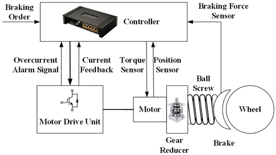
Figure 1.
Schematic Diagram of Electromechanical Braking Device.
When analyzing the mechanical transmission part, the following assumptions are made in this paper:
- (1)
- The dynamic response speed of motor current is faster than the dynamic response speed of pressure. In differential analysis of equations, the dynamic response of motor current can be ignored, and the control object is the clamping force. The torque output of the motor can be adjusted by the internal current loop.
- (2)
- The thrust is equal to the clamping force; that is, the influence of error caused by the transmission dynamics of the pressure wave is ignored.
- (3)
- The effects of long-term brake shoe wear are not considered, focusing on performance over short-term operational cycles.
- (4)
- The inertial force of the mechanical transmission part is equal to the inertial force acting on the force sensor, which means the inertial force can be expressed by the mass and acceleration of the mechanical transmission part.
- (5)
- The nonlinear friction is characterized by a combined static, Coulomb, and viscous model, capturing the dominant effects for control design.
To establish a clear dynamical model, a unified coordinate system is defined, as illustrated in Figure 1. The rotational motion of the motor and the linear motion of the brake shoe are considered. The positive direction of the motor rotation angle θe is defined as the direction that leads to the forward advancement (positive x-direction) of the brake shoe towards the brake shoe, thereby generating the clamping force Fh.
Under the above assumptions and coordinate system, the model for designing motor shaft rotation dynamics and mechanical part linear dynamics can be expressed by the following equations.
For the rotational part, according to Newton’s second law for rotation, the dynamics are governed by:
where J represents the total rotational inertia reflected to the motor shaft, Te is the electromagnetic torque generated by the motor, and Tr is the resistive torque converted from the mechanical transmission side, including the effect of friction. Moreover, is angular acceleration of the motor.
The relationship between the motor rotation and the linear displacement of the brake shoe is given by the transmission mechanism (e.g., ball screw). Assuming a lead of ls for the screw, the displacement relationship is:
For the linear motion part, applying Newton’s second law, the dynamics are:
where m is the total equivalent mass of the linearly moving parts, Fr is the thrust force generated by the transmission mechanism from the motor torque, and Ff is the total nonlinear friction force acting on the linear motion part. Fs is the elastic force from the brake shoe deformation, and Fh is the target clamping force acting on the brake shoe.
The force Fr is related to the motor torque Te and the transmission efficiency. Ignoring the dynamics of the transmission for simplicity, it can be expressed as:
The nonlinear friction force Ff is a combination of static, Coulomb, and viscous friction, which is a function of the linear velocity .
where Fc is the Coulomb friction magnitude, B is the viscous friction coefficient, and Fs represents the static friction.
3.2. Establishment of Pressure-Oriented Control Model
Since the total inertia of the motor and reduction gear, and brake shoe is very small, the above equation can be further simplified. When (6), (7), and (8) are brought into the linear dynamic model (7), the system can be expressed by a second-order equation:
Since the mass of the whole system is relatively small, the term including acceleration can be ignored. Thus, the above expression can be simplified as:
Since the total inertia of the motor, reduction gear, and brake shoe is very small (e.g., 0.2 kg in the experimental setup), the inertial term in (11) can be neglected, leading to the simplified first-order model in (12). This simplification is justified for the following reasons:
Quasi-Static Operation: The primary control objective is the precise tracking of clamping force. During the crucial clamping phase, the system operates in a predominantly quasi-static manner, where acceleration is minimal. Consequently, the inertial force is negligible compared to the dominant damping, spring, and pressure forces.
Bandwidth Justification: The operational bandwidth of the clamping force control loop is designed to be below 10 Hz, which is well below the mechanical natural frequency of the system (). Within this designed control bandwidth, the influence of the inertial term on the overall force tracking performance is insignificant.
It is acknowledged that inertial effects can manifest as high-frequency dynamics, such as the vibrations observable in the simulation results. However, these dynamics fall outside the primary bandwidth of interest for force control. The robustness of the proposed ADRC controller, which is designed to estimate and reject unmodeled dynamics and disturbances, effectively handles these high-frequency components, treating them as part of the total disturbance.
The purpose of this section is to obtain the characteristics of tread pressure under static friction and other influencing factors through linear analysis of the equation. By differential analysis of (12), we can get:
When the system is at a static working point , the characteristic curve of tread pressure can be described by the following expression:
Substituting (13) into (14), the following expression can be obtained:
Therefore, the pressure-oriented control model equation is obtained. It should be noted that due to the nonlinear characteristics of friction, the parameters in the above model are uncertain, and reasonable upper and lower limits should be set for each parameter in actual control.
The pressure model and the overall actuator model were respectively implemented in Simulink. A primary challenge in modeling friction lies in the accurate numerical representation of the stiction region, where the relative velocity approaches zero and the friction torque varies with the external applied torque. To implement this behavior robustly, a velocity-threshold-based switching logic was employed, the flow of which is illustrated in Figure 2.
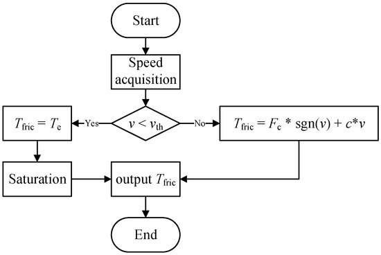
Figure 2.
Flowchart of the friction model implementation in Simulink.
The model continuously monitors the absolute value of the relative velocity, . This value is compared against a pre-defined velocity threshold, . This small, non-zero threshold was selected to avoid numerical chattering and to establish a well-defined boundary between the static and dynamic states, which is crucial for the stability of the simulation. When the system is identified to be in the stiction regime (), the conventional dynamic friction model is invalid. Here, the simulation mimics the physical world by activating a feedforward compensation channel. This channel calculates a friction torque that is equal and opposite to the motor’s instantaneous output electromagnetic torque, , thereby canceling it out to simulate a stationary condition. A critical aspect of this implementation is that the output of this feedforward path is limited by a saturation block. The saturation limit is set to the experimentally identified maximum static friction torque, ensuring that the simulated friction does not exceed physically plausible limits. Conversely, when the system is in the dynamic friction regime (), the friction torque is computed as the sum of the Coulomb and viscous components, as defined in (9), and this value is fed back into the mechanical model.
This switching logic, encapsulated within a dedicated Simulink subsystem (Figure 3), ensures a smooth transition between the static and dynamic friction states while maintaining numerical stability. The inclusion of the saturation block in the stiction branch is essential for preventing unrealistic torque accumulation and for accurately capturing the break-away phenomenon when motion initiates. This detailed elaboration on the model’s implementation logic and parameter sourcing is provided to fully address the reproducibility of the simulation results, particularly concerning the handling of the numerically delicate stiction phase.
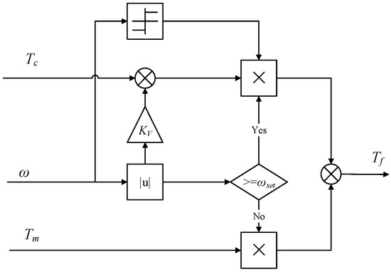
Figure 3.
Nonlinear friction simulation model.
The simulation model of the entire actuator was developed by integrating the above friction model as a module, as illustrated in Figure 4.
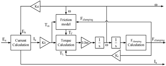
Figure 4.
Actuator simulation model.
The control objective of the clamping force control loop is the clamping force of the brake disc, and its control effect will directly affect the performance of the EMCU system. In this paper, two different working conditions, step and sine, are selected to verify the control performance of the clamping force control loop:
Working condition (1): step signal of 0~25 kN clamping force.
Working condition (2): sine signal of clamping force with frequency of 1 Hz, maximum value of 28 kN, and minimum value of 0 kN.
The step response curve of working condition (1) is analyzed. Under the control of the clamping force ring, the actual clamping force overshoot is σ = 1.58% < 5%. As shown in Figure 5a, it takes 72 ms to eliminate the braking gap, and the clamping force begins to increase, with a rise time of 184.9 ms. According to the response curve of the sinusoidal control signal input under working condition (2), the actual clamping force can change with the target clamping force signal, but there is a certain lag, and the lag time is 65 ms, which is within the controllable range, as shown in Figure 5b. Therefore, the response characteristics of the clamping force control ring meet the design requirements.
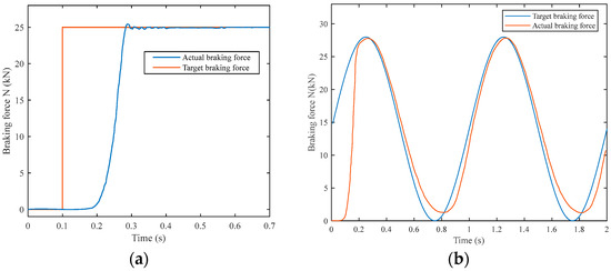
Figure 5.
Actuator simulation results. (a) Clamping force step response. (b) Clamping force sinusoidal response.
4. Experiment on Climbing Friction and Load Characteristics
4.1. Climbing Friction Test
In order to test the open-loop response of the system and the friction phenomenon in the braking scenario, a 1 A current is connected to the braking unit. When the push force of the brake head is stable, its value is recorded. Then increase the 1 A current each time until the current is 9 A. Then decrease the current by 1 A each time until the current is zero. The push-out force corresponding to different current values is recorded in turn (the push-out force should be stable and within the fluctuation range).
The experimental results in Figure 6 show a large error in the clamping force generated in three trials under the same target current parameters, with the error being more prominent at higher currents. This shows that due to the existence of nonlinear friction in the system, the output performance of the clamping force under the open-loop control of the electro-mechanical braking device is unstable, and there is a sudden change in load characteristics. On the other hand, in the braking force release stage, several experiments have shown that when the current decreases from 9 A to 6 A, the braking force does not decrease significantly. When the current is less than 6 A and continues to decrease, the braking force decreases significantly. When the current drops to 0 but does not fall back, the braking force is small but still exists.
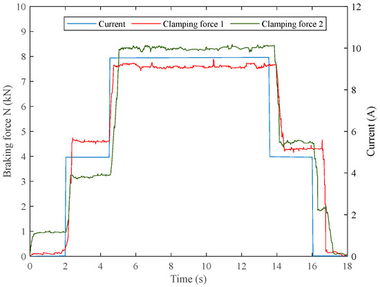
Figure 6.
System open-loop response curve.
Further, the current is set to a continuous input (0.05 A step), and the open-loop slope response curve is obtained again, as shown in Figure 7.
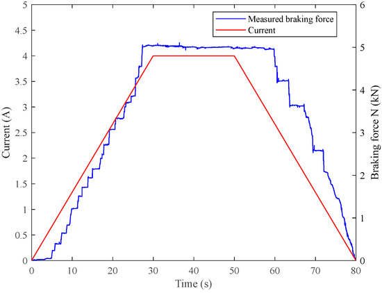
Figure 7.
Open-loop slope response curve of the system.
It can be seen that although the quadrature axis current parameters of the motor are continuously changing, the clamping force output is a step jump, showing a climbing phenomenon. In addition, compared with the rising process, it is more difficult for the clamping force to change with current parameters during the falling process; that is, it is difficult to relieve the clamping force after it is applied, and a hysteresis effect appears. This is mainly caused by the sudden change of the nonlinear friction and stiffness coefficient k of the brake shoe in Section 2.1.
4.2. Displacement–Pressure Load Characteristic Experiment of Actuator
In actual working conditions, the installation of force sensor may cause the strength and safety of the system to fail to meet the requirements of the train safety level, and repeated braking actions will lead to errors in the accuracy of the force sensor. Therefore, the displacement–pressure load characteristic curve of the actuator is attempted to be measured as a correction of the braking force observed value. Through the current closed loop, the braking force is applied, the brake disc pressure and the corresponding screw displacement are recorded respectively, and the data fitting is carried out to obtain the experimental results as shown in Figure 8 and Figure 9.
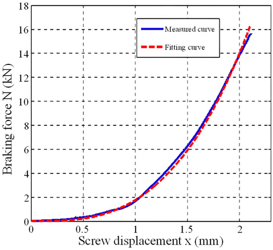
Figure 8.
Displacement–pressure load characteristics of the actuator (Experiment 1).
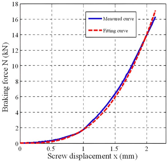
Figure 9.
Displacement–pressure load characteristics of the actuator (Experiment 2).
From the above load characteristic curve, it can be clearly seen that the braking pressure has a cubic relationship with the screw displacement. The fitting curve is in good agreement with the measured curve. The cubic coefficient obtained by fitting can be used as the braking force coefficient of the EBCU actuator to achieve the effect of parameter correction. The coefficient fitting results are shown in the following Table 2:
Table 2.
Coefficient fitting results of experiments.
The displacement pressure load characteristic function of the EBCU actuator can be obtained as follows:
However, experimental observations revealed that the braking force at the same actuator position differs between the pressure application and release phases, exhibiting a phenomenon analogous to the “hysteresis effect [19]” as shown in Figure 10. This hysteresis arises from the delayed recovery of brake disc deformation. Furthermore, the trajectories of the force–displacement curves do not coincide during the application and release processes.
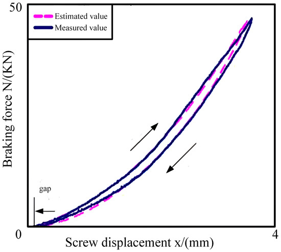
Figure 10.
Pressure Hysteresis Characteristics Experiment.
To describe the aforementioned process more accurately and predict the value of the braking force, the characteristic function obtained from experiments has been refined.
The relationship between brake disc pressure and displacement can be mathematically represented by a third-order model.
In Equation (17), the coefficients represent constants determined through curve fitting, while denotes the release gap illustrated in the figure above. The differential term is introduced to characterize the hysteresis phenomenon. As evidenced in the figure, the third-order polynomial provides a reasonably accurate representation of the relationship between braking force and displacement, effectively capturing its hysteretic characteristics.
The release gap in Equation (17) introduces a translational shift in the observed curve. Since brake disc wear may occur over prolonged operation, the control and measurement of the gap distance are of significant importance. To address this, a gap distance control algorithm is proposed herein. Upon completion of a full braking cycle—i.e., when the brake shoe returns to its initial position at zero displacement—the motor is reversed to retract the shoe sufficiently within the available spatial clearance. The brake motor is then advanced slowly to mitigate effects arising from impact inertia. When the brake shoe makes initial contact with the brake disc, the motor torque (current) exhibits a sudden variation.
The ratio , representing the rate of change of motor torque with respect to angular displacement, increases markedly. By defining a threshold S, contact is determined to occur when , indicating that the brake shoe has reached the real-time critical contact point. From this point, the motor is reversed by a predetermined angle, which is then converted into an actual retraction distance through the transmission mechanism, ensuring accurate positioning. In the event of brake disc wear, this critical contact point, along with the method described, enables real-time updating of the gap distance.
Figure 11 presents experimental results from five clearance distance calibration tests. Each symbol in Figure 11 represents a test. The initial clearance distance was set to 1 mm, with an adjustment distance of 0.2 mm. The vertical axis represents , indicating the rate of torque change with respect to angular displacement, while the horizontal axis denotes displacement. The motor speed was maintained at 100 r/min. At the contact point, exhibits a sharp increase and subsequently remains at an elevated level. This occurs because, after the contact point, the brake shoe has already engaged with the braking surface, whereby even minor displacements lead to significant variations in torque and braking force. The experimental results demonstrate the feasibility and effectiveness of the proposed clearance distance adjustment method.
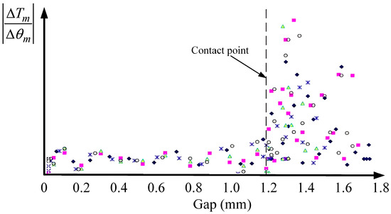
Figure 11.
Clearance Distance Measurement Experiment.
Figure 12 presents a comparison between the estimated braking force and the measured values from the force sensor. A step-type braking force is applied in region E, while a sinusoidal braking force is applied in region G. Experimental results indicate that the maximum error between the estimated and measured values is 4.8%, demonstrating the favorable tracking performance of the proposed braking force observer.
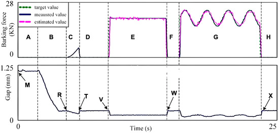
Figure 12.
Braking Force Observation and Clearance Distance Adjustment Experiment.
The initial clearance distance in the experiment is set to 1 mm, simulating brake disc wear. The brake shoe remains stationary at time M and advances with motor rotation at time R, resulting in a reduction of the clearance distance. In the subsequent phase, the clearance distance continues to decrease, and a minor braking force appears in region C. It should be noted that this braking force is not intended for vehicle deceleration but rather for clearance adjustment. Due to load deformation, the clearance distance in region C further decreases until it is adjusted to the desired value of 0.2 mm via braking force control. At time V, a target braking force of 20 kN is applied, and the estimated value from the model closely aligns with the measured value. After the braking force is applied, the brake shoe returns to the required initial position at time W. A sinusoidal target braking force is applied in region G, following a similar operational principle, with the clearance distance returning to its initial value at time X.
The positions at times W and X do not require the clearance adjustment strategy mentioned earlier, as brake disc wear during a single braking cycle is negligible. These positions can be directly determined from encoder readings. Actual clearance distance adjustments can be performed periodically based on the operational schedule of the train.
5. Principle of the ADRC Controller Based on Brake Force Observation
5.1. EMB System Control Structure Modeling
Based on the above modeling and analysis of the EMB system, a braking force controller based on nonlinear friction prediction is proposed in this paper. Since the motor rotor is basically in a locked state in the braking stage, the system adopts a double closed-loop structure of braking force current without considering the closed-loop control of speed. The specific framework is shown in Figure 13 below.
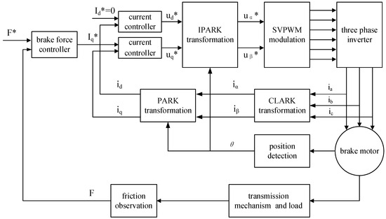
Figure 13.
Principal block diagram of double closed-loop control of braking force current of the braking motor.
A surface-mounted permanent magnet synchronous motor (PMSM) is applied to the EMB system, with key parameters shown in Table 3.
Table 3.
PMSM Parameters for EMB System Simulation and Experimental Studies.
Firstly, the core algorithm of the brake force controller is explained. Considering that the traditional PI regulator is difficult to meet the system’s demand for high-performance and high-precision control of the brake force, the auto disturbance rejection control (ADRC) technology is introduced in this paper. ADRC uses the extended state observer (ESO) to estimate all the total disturbances, including model uncertainties and external disturbances in real time, and compensates them in the control variables. Therefore, ADRC has strong robustness and is suitable for a strongly coupled nonlinear system such as PMSM. The design of ADRC includes the following four steps: arranging the transition process, designing the extended state observer, designing the state error feedback control law, and disturbance compensation.
It is known that the general current equation of PMSM in the dq synchronous rotating coordinate system is:
It can be seen from the above formula that there is an electromotive force coupled by the q-axis on the d-axis, and the q-axis contains not only the electromotive force coupled by the d-axis, but also the electromotive force generated by the rotor rotation, which is basically negligible in this system. The above four steps are modeled in turn.
5.2. Design of Extended State Observer
Since the current loop requires fast response, it is not necessary to arrange a transition process for it. Due to the vector control strategy adopted by the PMSM system in this paper, the reference current of axis d is 0, and the reference current of axis q is generated by the braking force controller.
Since the current loop requires fast response, for the d-axis current, in its current equation, when , when is considered as the total disturbance, the following form of extended state observer can be designed:
The corresponding discrete equation is:
where z2 can observe the total disturbance of the d-axis: .
Similarly, for the q-axis current, in its current equation , is considered the total disturbance, and the following form of ESO can be designed.
The corresponding discrete form is
where can observe the total disturbance of the q-axis.
5.3. State Error Feedback Control Law and Disturbance Compensation
Since the system considered in this paper can be approximated as a first-order system, the following (23) is used for error feedback of the dq-axis current.
For d-axis current, , so there is
For q-axis current, is generated by the braking force controller, so there is
Finally, the estimated disturbance is compensated in the control input.
The above shows the ADRC design process of the PMSM current loop, where s = d/q, summarized as follows:
Obviously, in the above current loop, the generated by the braking force controller is a very important input, which also directly affects the final torque output of the braking system. The input is obtained by the torque closed-loop. The design process of the brake force controller is introduced below.
Theoretically, the output torque of the motor is proportional to the q-axis current. However, due to the existence of nonlinear friction, the output torque at the end of the transmission mechanism will be smaller than the torque output by the motor shaft. Therefore, it is necessary to observe and compensate for the nonlinear friction in real time. In the third section, the nonlinear friction characteristics of the system have been systematically studied, and a “static, Coulomb, and viscous friction” model has been obtained. The final output force of the motor end predicted by the model can be expressed as . The first part of Ff represents static friction and Coulomb friction, the second part represents viscous friction, which is related to speed, and Fs represents the braking force output by the end of the mechanism. has been measured in Section 3.
After the real-time braking force is obtained through observation, it can be compared with the target braking force, and the force closed-loop controller is designed to output the target in the current loop. The force closed loop is also designed by the ADRC algorithm. Because its structure is relatively simple and is not disturbed by the nonlinearity of the motor system, the first-order ADRC algorithm can be directly used, so it will not be repeated here.
5.4. ADRC Parameter Tuning and Implementation Details
The performance of the ADRC largely depends on the appropriate selection of its parameters, namely the observer gains and , the state error feedback gain , and the discrete sampling time . This subsection details the values used and the methodology employed for tuning these parameters to ensure robust controller performance.
- Sampling Time ():
The discrete implementation of the ESO and the control law requires a fixed sampling time. The value was selected as s (100 µs). This choice is based on the electrical time constant of the PMSM and the switching frequency of the inverter, ensuring that the digital control loop is sufficiently fast to capture the system dynamics without introducing significant discretization errors.
- 2.
- Observer Gains ():
The gains of the Extended State Observer (ESO) are crucial for accurate and rapid estimation of the system states and the total disturbance. They were tuned based on the observer bandwidth method. The observer bandwidth was set to be 5–10 times the controller bandwidth to ensure the ESO dynamics are significantly faster than the controlled system’s dynamics.
The continuous-time observer gains are placed according to the characteristic equation , yielding:
For the system implementation, an observer bandwidth of rad/s was chosen. The corresponding discrete gains for the ESO (Equations (23) and (24)) were then calculated using the zero-order hold (ZOH) discretization method, resulting in:
- 3.
- State Error Feedback Gain ():
The proportional gain for the state error feedback law (Equations (17) and (18)) determines the response speed of the current loop. It was tuned to achieve a critical damping response for the first-order system approximation. The value was initially derived based on the plant model and then fine-tuned experimentally to balance response speed and overshoot. The final value used in both simulation and experiments is Kp = 0.85.
In conclusion, Table 4 below presents the main parameters of ADRC used for the simulation and experimental studies of the EMB system.
Table 4.
ADRC Parameters for EMB System Simulation and Experimental Studies.
These parameters were validated through both simulation in MATLAB/Simulink 2022b and extensive experimental tests, confirming that the ADRC achieves the desired disturbance rejection and tracking performance as presented in Section 6.
5.5. Simulation Validation and Comparative Analysis
To validate the effectiveness of the proposed ADRC controller and provide a quantitative comparison with conventional methods, a comprehensive simulation study was conducted using the MATLAB/Simulink platform. The simulation model incorporates the high-fidelity EMB actuator model established in Section 3, including explicit representation of nonlinear friction characteristics. A conventional PI controller, widely adopted in industrial applications, serves as the baseline for performance comparison.
The simulation scenario spans 0.5 s and includes two step changes in reference braking force: from 0 to 8 kN at 0.1 s and from 8 to 12 kN at 0.3 s. External disturbances were introduced to evaluate controller robustness. The comparative simulation results are presented in Figure 14, with quantitative performance metrics summarized in Table 5.
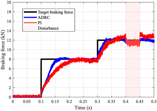
Figure 14.
Comparative simulation of ADRC and PI controllers: Braking force tracking performance under step changes.
Table 5.
Performance Comparison between ADRC and PI Controllers.
The simulation results clearly demonstrate the superior performance of the proposed ADRC controller. For the first step change (from 0 to 8 kN), the ADRC controller achieves a transient time of only 0.05 s, significantly outperforming the PI controller, which requires 0.21 s. This rapid response is accompanied by minimal overshoot—only 0.4 kN for ADRC compared to 1.2 kN for the PI controller. The performance advantage persists during the second step change (from 8 to 12 kN), where ADRC again exhibits a faster response with a transient time of 0.03 s versus 0.05 s for the PI controller.
In terms of steady-state accuracy, the ADRC controller maintains force tracking errors below 0.5 kN, whereas the PI controller exhibits a steady-state error of 0.9 kN. The pronounced performance superiority of ADRC is attributed to its inherent capability to actively estimate and compensate for nonlinear disturbances through the Extended State Observer. In contrast, the fixed-gain PI controller struggles to maintain consistent performance due to its inability to adapt to system nonlinearities and external disturbances. These simulation results provide strong validation of the proposed control strategy before proceeding to physical experimental verification.
6. Experimental Verification of the ADRC Controller Based on Brake Force Observation
Finally, upon completion of the control unit circuit design, we performed PCB fabrication, component soldering, system debugging, and enclosure assembly to successfully develop the electromechanical braking system control unit. The motor test platform used in this experiment mainly consists of three components: a permanent magnet braking motor, ball screw system, and brake friction pads, as shown in Figure 15 below.
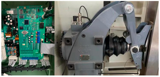
Figure 15.
Experimental environment.
The experimental environment is shown in Figure 15. The left figure is the permanent magnet braking motor and mechanical actuator, with a screw to drive the braking pad. The controller board is shown on the right. It can conduct the control algorithm of the EMB system, and realize the communication function with the host PC. The detailed design of the controller board is shown in Figure 16.
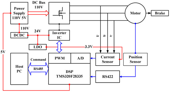
Figure 16.
Braking System Structure Diagram.
The electric braking experimental platform is built based on a TMS320F28335 DSP, which receives command signals from a host PC via RS-485 communication and generates PWM outputs to drive an Inverter IC module controlling the Motor Brake. The DC Bus voltage is 110 V, and through a DC/DC converter, 24 V was generated for motor drive logic and further stepped down by an LDO to 3.3 V for DSP core voltage. The feedback loop is provided by a current sensor and a position sensor, with sensor analog signals digitized by the DSP’s A/D converters. The position sensor interfaces via RS422 for data transmission, while system-level protections include overcurrent detection and DC bus voltage monitoring. All modules—including power conversion, motor drive, sensing, and communication—are integrated into a unified hardware platform, enabling real-time control algorithm validation and dynamic braking performance analysis.
Experiments are carried out by connecting the force sensor and using the braking force observation model as the only feedback quantity. When the step target braking force of 10 kN is input in the initial state, and the target braking force is adjusted to 16 kN at 0.42 s, the force sensor is connected, and the brake force observer is directly used for the experiment separately. The results are as follows in Figure 17 and Figure 18.
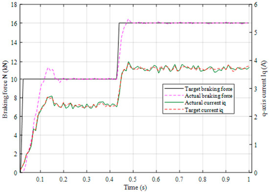
Figure 17.
Braking force output experiment based on force sensor.
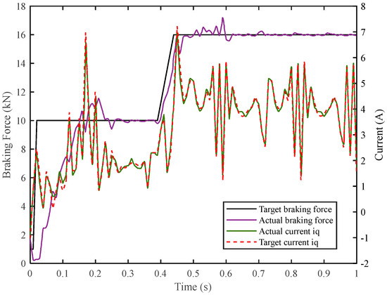
Figure 18.
Braking force output experiment based on braking force prediction.
By comparing the two experimental results, it can be found that the error between the actual iq and the target iq is kept within 2%, which shows that the current loop designed has good tracking performance. In the experiment of using force sensor to establish a closed loop, the maximum overshoot is 1.8 kN. The system reaches steady state at 0.2 s, and the q-axis current has no obvious fluctuation after reaching steady state, which indicates that the system is in a relatively stable locked rotor state, and the real-time torque collected by the force sensor has no obvious fluctuation. After the braking force prediction model is adopted, the maximum overshoot is 2.2 kN, and the system basically reaches the steady state at 0.28 s. However, after that, the current still fluctuates significantly, and the overshoot is close to 100%, indicating that the predicted braking force is still changing at this time. In order to eliminate the error caused by this jump, the q-axis current is still adjusting in real time, so as to finally ensure that the error between the actual braking force and the target braking force is kept within 1 kN. It shows that the controller design based on brake force prediction is successful. Another interesting experimental result is that at zero time, a negative q-axis current appears in Figure 1. This is because the system is completely static at this time, and the predicted maximum static friction is greater than the target braking force. In actual experiments, this may cause the motor to reverse, thus affecting the stability and safety of the entire system. In subsequent research, it can be eliminated through state judgment.
7. Conclusions
This paper tackled the critical challenge of nonlinear friction in Electromechanical Braking (EMB) systems by developing a robust, sensor-less clamping force control strategy. The cornerstone of this strategy is an Auto-Disturbance Rejection Control (ADRC) algorithm, synergistically integrated with a novel braking force observer. Substantial findings from this research span the domains of modeling, control design, and experimental validation, and are quantifiably summarized as follows.
First, a high-fidelity, railway-oriented EMB model was established and validated, which explicitly incorporates static, Coulomb, and viscous friction. Experiments uniquely identified a key cubic relationship between screw displacement and braking pressure (coefficient ≈ 1.75), providing a foundational reference for force observation.
Furthermore, a novel control strategy was developed, centered on an ADRC framework integrated with a dedicated braking force observer. Comparative simulations demonstrate its clear advantages over conventional PI control, achieving a 76% faster response in initial transients and a 67% reduction in overshoot. This enhanced performance stems from the deep fusion of real-time, model-based feedforward compensation and active disturbance estimation, effectively handling both characterized nonlinearities and unmodeled dynamics without a physical force sensor.
Experimental results conclusively validate the superior performance of the proposed controller. Hardware-in-the-loop tests under standard step and sinusoidal inputs demonstrated that the controller in its critical sensor-less mode maintains a steady-state force error of less than 1 kN with a settling time of 0.28 s, while the current loop exhibits exceptional tracking performance with a q-axis current error within 2%. These results represent a significant performance level for an observer-based scheme. Notably, even when benchmarked against simulations with ideal force sensor feedback—which showed a minimal overshoot of 1.58% and a rise time of 184.9 ms—the proposed sensor-less controller delivers robust and highly competitive performance.
In conclusion, the methodology and experimental evidence presented in this study confirm a viable and effective path toward high-performance, sensor-less EMB systems. The work provides a solid foundation for the development of more intelligent and fully electrified braking solutions in rail transportation. Future work will extend the experimental validation to more complex and realistic railway braking scenarios, such as emergency stops and variable load conditions, to further advance the technology readiness of the proposed strategy.
Author Contributions
Methodology, R.J. and K.L.; Software, R.J., W.Z. and R.M.S.; Validation, R.J. and W.Z.; Formal analysis, R.J. and K.L.; Investigation, R.J.; Resources, K.L.; Data curation, R.J.; Writing—original draft, R.J.; Writing—review & editing, R.J., K.L. and R.M.S.; Visualization, R.J., W.Z. and R.M.S.; Supervision, K.L.; Project administration, K.L.; Funding acquisition, K.L. All authors have read and agreed to the published version of the manuscript.
Funding
This research was funded by Tianjin Navigation Instruments Research Institute, grant number 62602010313, and Aero Science Foundation of China, grant number 20240007069003.
Data Availability Statement
Data are contained within the article.
Conflicts of Interest
The authors declare no conflict of interest.
Abbreviations
The following abbreviations are used in this manuscript:
| EMB | electro-mechanical braking |
| SRM | switched reluctance motor |
| SMO | sliding mode observer |
| SESO | switching extended state observer |
| ESO | extended state observer |
| EBCU | electronic brakeforce control unit |
| ADRC | auto disturbance rejection control |
| PMSM | permanent magnet synchronous motor |
References
- Yang, C.; Chen, Z.; Wang, J.; Chen, Z. Rapid Simulation Method for Electro-Pneumatic Composite Braking System Based on Equivalent Modeling. In Proceedings of the 2024 6th International Conference on Industrial Artificial Intelligence (IAI), Shenyang, China, 21–24 August 2024; pp. 1–6. [Google Scholar]
- Pavlov, N.; Dimitrov, V. Influence of the braking on the comfort during positioning of a metro train. In Proceedings of the 2019 11th Electrical Engineering Faculty Conference, Varna, Bulgaria, 11–14 September 2019; pp. 1–4. [Google Scholar]
- Zhang, J.; Liu, W.; Tian, Z.; Xu, Q.; Ma, Q.; Pan, Z. Canceling Onboard Braking Resistance and Optimal Design of Energy Feedback Systems in Urban Rail. IEEE Trans. Transp. Electrif. 2024, 10, 8575–8584. [Google Scholar] [CrossRef]
- Baek, S. Comparative Evaluation of Electro-Mechanical Brake Clamping Force Estimation and Sensor Compensation Control Method for High-Speed-Train. IEEE Access 2024, 12, 45644–45653. [Google Scholar] [CrossRef]
- Luo, M.; Wu, M.-L.; Wang, X.-Y. Study on Reliability Test for Brake Control Execution Unit of Rail Transit Vehicle. In Proceedings of the 2010 International Conference on E-Product E-Service and E-Entertainment, Henan, China, 7–9 November 2010; pp. 1–4. [Google Scholar]
- Chen, L.; Zhou, Z.P.; Wan, Z.C.; Wan, G.C.; Tong, M.S. Fast Braking of Segmented Electro-Pneumatic Braking System by Using Variable-Universe Fuzzy-PID Controller Optimized by Genetic Algorithm. IEEE Trans. Veh. Technol. 2024, 74, 2610–2619. [Google Scholar] [CrossRef]
- Marchenko, D.; Dykha, A.; Matvyeyeva, K. Development of an Electropneumatic Vehicle Brake Drive. In Proceedings of the 2023 IEEE 5th International Conference on Modern Electrical and Energy System (MEES), Kremenchuk, Ukraine, 27–30 September 2023; pp. 1–6. [Google Scholar]
- Mengling, W.; Tianhe, M.; Chun, T.; Jun, Y.; Maolin, C. Development trends of train braking technology. China Railw. Sci. 2019, 40, 134–144. [Google Scholar]
- Houhua, J.; Ruixue, F.; Qinggan, L. Design and Test of Electro-Mechanical Brake Experiment System. In Proceedings of the 2022 6th CAA International Conference on Vehicular Control and Intelligence (CVCI), Nanjing, China, 28–30 October 2022; pp. 1–5. [Google Scholar]
- Zhao, Y.; Li, F.; Li, B.; Shi, Y.; Wu, L.; Yang, C.; Gui, W. Hybrid Power Control Strategy for Electromechanical Braking System Based on Sliding Mode Approach. IEEE Trans. Ind. Electron. 2025, 1–10. [Google Scholar] [CrossRef]
- Lei, C.; Peng, Y.; Zhang, W.; Wu, M. The research of the force control of electric-actuator based on the principle of feedback linearization and adaptive control. In Proceedings of the CSAA/IET International Conference on Aircraft Utility Systems (AUS 2024), Xi’an, China, 16 October 2024; pp. 1587–1595. [Google Scholar]
- Line, C.; Manzie, C.; Good, M.C. Electromechanical Brake Modeling and Control: From PI to MPC. IEEE Trans. Control. Syst. Technol. 2008, 16, 446–457. [Google Scholar] [CrossRef]
- Ma, R.; Zhang, H.; Yuan, M.; Liang, B.; Li, Y.; Huangfu, Y. Chattering Suppression Fast Terminal Sliding Mode Control for Aircraft EMA Braking System. IEEE Trans. Transp. Electrif. 2021, 7, 1901–1914. [Google Scholar] [CrossRef]
- Jo, C.; Hwang, S.; Kim, H. Clamping-Force Control for Electromechanical Brake. IEEE Trans. Veh. Technol. 2010, 59, 3205–3212. [Google Scholar] [CrossRef]
- Omekanda, A.M.; Lequesne, B.; Klode, H.; Gopalakrishnan, S.; Husain, I. Switched reluctance and permanent magnet brushless motors in highly dynamic situations: A comparison in the context of electric brakes. IEEE Ind. Appl. Mag. 2009, 15, 35–43. [Google Scholar] [CrossRef]
- Krishnamurthy, P.; Lu, W.; Khorrami, F.; Keyhani, A. Robust Force Control of an SRM-Based Electromechanical Brake and Experimental Results. IEEE Trans. Control. Syst. Technol. 2009, 17, 1306–1317. [Google Scholar] [CrossRef]
- Xu, Z.; Gerada, C. Enhanced Estimation of Clamping-Force for Automotive EMB Actuators Using a Switching Extended State Observer. IEEE Trans. Ind. Electron. 2023, 71, 2220–2230. [Google Scholar] [CrossRef]
- Xu, Z.; Gerada, C. Enhanced Force Estimation for Electromechanical Brake Actuators in Transportation Vehicles. IEEE Trans. Power Electron. 2021, 36, 14329–14339. [Google Scholar] [CrossRef]
- Zhao, Y.; Lin, H.; Li, B. Sliding-Mode Clamping Force Control of Electromechanical Brake System Based on Enhanced Reaching Law. IEEE Access 2021, 9, 19506–19515. [Google Scholar] [CrossRef]


Disclaimer/Publisher’s Note: The statements, opinions and data contained in all publications are solely those of the individual author(s) and contributor(s) and not of MDPI and/or the editor(s). MDPI and/or the editor(s) disclaim responsibility for any injury to people or property resulting from any ideas, methods, instructions or products referred to in the content. |
© 2025 by the authors. Published by MDPI on behalf of the World Electric Vehicle Association. Licensee MDPI, Basel, Switzerland. This article is an open access article distributed under the terms and conditions of the Creative Commons Attribution (CC BY) license (https://creativecommons.org/licenses/by/4.0/).