Article

Experimental Study on Low-Temperature Thermal Management of Lithium Battery with Pulsating Heat Pipe

School of Computer and Information Engineering, Fuyang Normal University, Fuyang 236041, China
*
Author to whom correspondence should be addressed.
World Electr. Veh. J. 2025, 16(11), 597; https://doi.org/10.3390/wevj16110597
Submission received: 29 September 2025 / Revised: 25 October 2025 / Accepted: 28 October 2025 / Published: 29 October 2025
(This article belongs to the Section Storage Systems)

Abstract

To address the serious decline in charge and discharge performance of lithium batteries in low temperatures, this paper proposes a thermal management scheme with pulsating heat pipes, which effectively achieves the advantages of pulsating heat transfer in heat pipes and large-scale equalization heating in aluminum plates. Optimal energy consumption thermal management strategies (OECTMS) and optimal performance thermal management strategies (OPTMS) were proposed. The OECTMS aims to reduce the system energy consumption while ensuring thermal management performance, whereas the OPTMS is intended to maximize the performance of the heating system, ensuring that lithium batteries achieve optimal thermal and electrical performance. Experimental results show that in low-temperature discharge scenarios (−10 °C, −20 °C, and −30 °C), compared with batteries without TMS, the OECTMS implements intermittent heating for the battery, achieving discharge capacities as high as 60.06 Ah, 54.76 Ah, and 48.66 Ah, which correspond to increases of 10.67%, 14.11%, and 29.83%, respectively. For the OPTMS, which applies continuous heating to the battery, the discharge capacities are increased by 19.5%, 23.7%, and 56.6% compared with batteries without TMS at a 0.5C rate. Notably, the battery with the OPTMS, which originally could not discharge at all under −30 °C, achieves a discharge capacity of 61.55 Ah, exhibiting a higher discharge capacity at a 1.5C rate. Furthermore, compared with the OECTMS, the battery temperature under the OPTMS is consistently maintained above 0 °C, and the temperature changes stably throughout the discharge process without temperature spikes. This manuscript introduces pulsating heat pipe technology and proposes a novel low-temperature thermal management scheme and provides new insights for the efficient operation of lithium batteries in low-temperature environments.

1. Introduction

The rapid development of the automotive industry has brought about earth-shaking changes to the world, especially the flourishing development of electric vehicles (EVs) worldwide [1]. As the energy source of EVs, the power battery plays a crucial role. Lithium batteries have become the core energy source of EVs due to their outstanding advantages, such as high energy density, good cycling characteristics, and no memory effect. The performance and safety of their systems are particularly critical [2]. Users generally express the core concern of low-temperature endurance in the promotion and application of EVs. Range anxiety comes from the serious decline in the performance of the power battery in low temperatures. As the core energy source of vehicles, it directly affects the performance of vehicles [3,4]. Low temperature not only affects the performance of vehicles but also brings irreversible degradation of battery performance (decrease in capacity retention) and irreversible damage (internal structural changes, low-temperature lithium deposition), accelerating battery aging [5,6]. As the primary guarantee for battery performance and safety, the battery thermal management system should optimize the working environment of the battery, control the battery to operate within the allowable temperature range, and improve the performance. Therefore, attempting to develop an efficient thermal management system to solve the performance degradation dilemma faced by batteries in low temperatures has important academic value and practical significance and is also in line with the current trend of “high-end” development of battery technology.
The main technical solutions for low-temperature thermal management can be divided into two categories: internal heating and external heating. The internal heating method increases heat generation by creating a large internal resistance at low temperatures, thereby achieving heating of the battery [7]. Its main features are no intermediate steps for heat transfer, no need for additional heat transfer systems or circuit components, ensuring uniform heating of the battery, and overall fast and efficient heating [8]. In specific applications, internal heating can be divided into alternating current heating and self-heating. The alternating current heating is affected by factors such as application voltage, frequency, current form, and current amplitude [9,10,11]. In related studies, alternating current can effectively heat a lithium battery during low-temperature charging, but under low-frequency application conditions, it is prone to lithium-ion deposition [12] and battery aging [13]. Although there have been many publicly reported studies on the internal heating of lithium batteries, the technology is still in the theoretical exploration stage, and there is still a long way to go before it can be practically applied.
External heating refers to heating outside the battery, mainly including forced air heating, flowing liquid heating, contact thermal resistance heating, heat pipe heating, and composite thermal management technologies of two or more of the above [14]. Air heating is the use of a heating device to heat the air and then use hot air to preheat the battery and heat the lithium battery through thermal conduction. However, the air heating system has blind spots inside the battery compartment that cannot be reached, resulting in temperature uncertainty and low efficiency of the air heating system [15]. The heating technology using liquid as a heat exchange medium refers to heating battery packs through thermal conduction. In current research, by arranging some sealed pipelines and using a heat transfer working fluid to flow through the pipelines to transfer heat to the battery pack, in addition to traditional liquid flow preheating devices, tube bundle liquid flow heating devices are also designed to make the battery pack lightweight. Compared with air heating, using liquid heat flow for heating can achieve higher heat transfer efficiency. However, the traditional method of passing liquid into the bottom of the battery box has higher requirements for the sealing of the battery box, and its reliability is more difficult to guarantee [16]. Contact thermal resistance heating mainly refers to the use of heating elements to heat the battery. It mainly includes two heating methods: metal heating film and PTC material. Contact thermal resistance heating can achieve a good heating effect, but the heating system has insulation failure, electrical safety, and overheating risks [17].
Heat pipe heating mainly refers to the transfer of heat generated by electric heating to the heat pipe. By utilizing the bidirectional thermal conductivity of the heat pipe, the condensation end is used as the battery heating end, and the heat is transferred to the heat absorption end through internal fluid motion. Its main principle lies in the advantages of high thermal conductivity, high heat flux density, flexible contact structure, and good temperature equalization effect of heat pipes [18,19], which have been widely used in the field of heat dissipation in microelectrical systems such as electronic chips for a long time. There are many current studies on the heat dissipation of lithium batteries around heat pipes [20,21,22]. He [23] proposed a thermal management system with a combination of heat pipes and liquid-cooled plates; the coverage angle of the aluminum plate on the battery had the greatest impact on the system cooling performance. When the height, thickness, coverage angle of the aluminum plate on the battery, and coverage angle of the heat pipe were greater than 50 mm, 2 mm, 75°, and 60°, respectively, it could ensure that the battery obtained a good working temperature range. And the highest temperature was 37.58 °C, with a temperature difference of 3.67 °C. Liang [24] proposed a battery thermal management with flat plate heat pipes and conducted cooling tests on a cylindrical battery at a discharge rate of 5C. The results showed that using flat plate heat pipes to cool the battery pack could limit its temperature to within 50 °C, and the temperature difference in the battery pack did not exceed 5 °C.
However, research has found that there are not many studies on low-temperature thermal management around heat pipes, although there are also literature reports on related applications [25,26]. Chen [27] designed a low-temperature heating module for a battery with heat pipes, inserting the heat transfer section of the heat pipe between the large side of the battery and the battery. Under low-temperature conditions of −20 °C, the heat pipe can ensure continuous operation, which proves the possibility of using the heat pipe for low-temperature heating management of electric vehicle power batteries. From the above analysis, it can be seen that heat pipe heating has a bright future. However, it still has significant limitations. Firstly, the use of heat pipes for battery thermal management is limited, and publicly reported literature indicates that heat pipes are mostly used for high-temperature thermal management. However, there are few literature reports on low-temperature thermal management related to it. Secondly, the integration research of heat pipes with other schemes is not sufficient. Pulsating heat pipes are only a heat transfer device. How to efficiently match them with other preheating technologies, fully utilize or maximize their role as an efficient heat transfer device, and achieve the goal of low-temperature thermal management of batteries is the key.
To address the above limitations, this study proposes a low-temperature thermal management system for lithium batteries with pulsating heat pipes. The effectiveness of the proposed system is examined in different low-temperature scenarios, aiming to fill the gap in research on pulsating heat pipes in low-temperature thermal management of lithium batteries and expand the application scenarios of pulsating heat pipes. Undoubtedly, this has significant academic significance. The innovation and contribution of the research are as follows: (1) a low-temperature thermal management scheme with pulsating heat pipes has been proposed, laying the foundation for efficient battery thermal management; (2) energy consumption and optimal performance thermal management strategies for low-temperature scenarios have been proposed, providing new insights for low-temperature heating of batteries; and (3) the efficiency and reliability of the pulsating heat pipe thermal management system and corresponding strategy have been verified, expanding the application scope of heat pipes.

2. Materials and Methods

Preliminary preparations were made from the aspects of pulsating heat pipe design and manufacturing, design of pulsating heat pipe thermal management system, design of thermal management strategy, performance testing bench construction, and performance testing projects. The specific contents are as follows:

2.1. Pulsating Heat Pipe Design and Manufacturing

Pulsating heat pipes mainly consist of two parts: the internal working fluid and the pipe body. Firstly, the choice of working fluid. Working fluids can be divided into traditional working fluids and non-traditional working fluids (nanofluids). Nanofluids prepared with metal nanoparticles can significantly enhance the heat transfer ability of the working fluid [28], while also exhibiting higher stability. Titanium dioxide has good durability/heat resistance, chemical stability, dispersion stability, strong environmental friendliness, and is safe for humans [29,30]. Meanwhile, titanium dioxide has a wide range of sources and low production costs [31,32]. The basic solutions of nanofluids mainly include water, ethanol, propanol, paraffin oil, etc. Nanofluids with ethanol and propanol exhibit superior thermal conductivity [33,34], mainly due to the functional groups of double bonds in ethanol, which facilitate the formation of stable compounds with other substances. In addition, ethanol has lower dynamic viscosity and greater latent heat and specific heat compared to water, which is beneficial for the low-temperature start-up of heat pipes. Based on the aforementioned analysis, commercially available titanium dioxide nanofluid was adopted as the working fluid for the pulsating heat pipe in this study, with ethanol serving as the base solution. According to relevant literature, the heat transfer performance of the heat pipe is optimal when the filling ratio is 50% and the volume concentration of the nanofluid working fluid is 2% [2].
Next, the design of pulsating heat pipes needs to adapt to the battery thermal load, respond to changes in battery thermal load, and meet heating requirements. The selection of pulsating heat pipes requires consideration of heat pipe parameters and battery characteristics. The thermal conductivity of pipes is one of the main factors affecting the heat transfer capacity of pulsating heat pipes. The selected material should have good thermal conductivity to withstand higher temperatures and be compatible with the working fluid. Choose copper material (copper has a high thermal conductivity of about 400 W/m·K [35]) as the heat pipe material. A circular cross-section helps the liquid film to always adhere to the inner wall of the heat pipe, better absorbing and dispersing heat from the evaporation and condensation sections [36]. Additionally, a circular cross-section has lower flow resistance, and the cross-section of the pulsating heat pipe is determined to be circular. The number of turns of pulsating heat pipes is directly related to the total heat flux and is also limited by practical conditions. According to the actual size of the battery and the constraints of the thermal management system, the pulsating heat pipe should be designed to cover the large side of the battery as much as possible, ensuring that heat is transferred to the surface of the battery as much as possible. The number of turns is determined to be 5. According to the actual design of the thermal management system with pulsating heat pipes, the length of the pulsating heat pipe evaporation section is selected as 45 mm, and the length of the condensation section is 183 mm.
The operation of pulsating heat pipes is based on the oscillatory motion of gas and liquid plugs, and the relative strength must comply with relevant standards [37] to achieve good oscillatory motion and meet heat transfer requirements. Furthermore, considering the relationship between the inner diameter size and the frictional resistance of the working fluid, the minimum inner diameter is also subject to certain constraints [38]. The specific description is as follows:
B o = E o = ( ρ l ρ v ) g σ D 2
D max 2 σ ( ρ l ρ v ) g
0.7 σ ( ρ l ρ v ) g D i 2 σ ( ρ l ρ v ) g
where σ is the surface tension of the working fluid (N/m); D is the inner diameter of the heat pipe (m); g is the gravity acceleration (N/kg); ρ v is the density of gas plugs (kg/m3); ρ l is the density of liquid plugs (kg/m3); B o is the bond number; E o is the Euler number.
The inner diameter of pulsating heat pipes is usually within the range of 1 mm to 8 mm [39]. With actual processing technology, the designed inner diameter is determined to be 5 mm. Finally, a vacuum pump is used to evacuate the heat pipe, and nanofluid is injected into the heat pipe (titanium dioxide nanofluid with a filling rate of 50% and a working fluid concentration of 2% has the best heat transfer ability). Then, the heat pipe is sealed, and finally, the pulsating heat pipe is obtained.

2.2. Design of Pulsating Heat Pipe Thermal Management System

The pulsating heat pipe thermal management system mainly includes core components such as a lithium battery, high thermal conductivity pulsating heat pipes, aluminum homogenization plates, heating plates, and thermal management control subsystems. As shown in Figure 1, a commercially available lithium iron phosphate battery (Yiwei Lithium Energy Co., Ltd., Huizhou, China) with a capacity of 68 Ah is selected as the research object. Adopting a heating scheme that combines mica heating plates and pulsating heat pipe heat exchangers for thermal management of the battery in low-temperature environments. That is, adding a pulsating heat pipe heat exchanger (Laboratory self processing, Harbin, China) on the large side of the battery, wherein the pulsating heat pipe heat exchanger consists of the pulsating heat pipe mentioned earlier and an aluminum homogenization plate (Laboratory self processing, Harbin, China). The main function of the aluminum homogenization plate is to uniformly transfer the temperature to the large side of the battery, achieving uniform heating of the large side of the battery. The heat pipe is embedded in the homogenization plate to achieve sufficient contact between the two, and the heat pipe evaporation end is in contact with the heating plate. The heat is transferred from the evaporation end of the heat pipe to the condensation end, while the heat from the condensation end is transferred to the surface of the battery through the aluminum homogenization plate, thereby achieving heating of the battery. The detailed parameters are shown in Table 1, and the specific control strategy will be elaborated on in Section 2.3.

2.3. Design of Thermal Management Strategy

The original intention of low-temperature heating management for lithium batteries is to reduce potential safety risks such as performance degradation and lithium deposition caused by low temperature. The low-temperature heating management strategies usually require consideration of the target temperature of the lithium battery. Generally speaking, a battery can be freely charged and discharged above 0 °C. Sometimes, it is necessary to reduce the impact of environmental temperature on battery performance and ensure that the battery is within the ideal temperature range. However, this ignores the parasitic energy consumed by the system, as the heating element consumes a significant amount of energy for low-temperature heating. It is of great significance to ensure the low-temperature performance of the battery while reducing the energy consumption of the pulsating heat pipe thermal management system.
Therefore, it is very necessary to have a real-time temperature control strategy, which can ensure that the average temperature of the battery is within the allowable temperature range, effectively exert the electrical performance of the battery, and reduce the energy consumption of thermal management systems. Therefore, this paper proposes an optimal performance thermal management strategy (OPTMS) and an optimal energy consumption thermal management strategy (OECTMS). OPTMS aims to keep the battery operating within the optimal temperature range by controlling the continuous operation of the heating element and maximizing the performance of the battery; OECTMS aims to ensure that the battery operates within the allowable temperature range and reduce the system energy consumption caused by heating plates.
OPTMS ensures that the heating element operates throughout the entire process without the need for control. However, OECTMS requires the control of mica heating plates. Although PID control has significant advantages in industrial control, such as obvious control effects, simple system composition, and easy adjustment of control parameters [40]. However, lithium battery systems exhibit highly nonlinear time-varying characteristics, and PID control technology shows significant lag for thermal management system control. Fuzzy control, as a representative of control theory that can be implemented industrially, is suitable for dealing with complex problems such as nonlinearity, multidimensionality, and multi-field coupling [41]. Therefore, a PID controller with fuzzy control is developed for the OECTMS, as shown in Figure 2. Aim to implement thermal management strategies by controlling the power of mica heating plates.
The design of a fuzzy PID controller includes the controller structure, fuzzification of controller input and output, and formulation of controller control rules.
(1)
Controller structure
The control objective is the temperature of the lithium battery, and the system execution element is the mica heating element. The deviation and deviation change rate between the expected temperature and the actual temperature value of the battery are selected as input variables, and the correction parameters are selected as output variables. The correction parameters are used to supplement and optimize the control parameters of the PID controller, and the output variable of the controller is the power of the heating element.
(2)
Fuzzification of controller input and output
The input and output variables are described as ML (negative large), MI (negative medium), MP (negative small), ZO (zero), FP (positive small), FI (center), and FL (positive large). After multiple tests of the positive definite controller combined with the thermal management system and experimental structural analysis, the input variables’ domain was finally set to [−6, 6], the output variables’ domain was set to [−2, 2], and a triangular function was selected as the membership function of the variables.
(3)
Controller control rules
The control rules usually require reference to the industry’s long-term accumulated experience and analysis of actual experimental results to ultimately conclude. Based on the team’s previous research on low-temperature heating control technology for power batteries and industry experience in battery management systems, the control rule tables for various parameters of the fuzzy controller were finally obtained, as shown in Table 2, Table 3 and Table 4.

2.4. Low-Temperature Performance Testing Bench

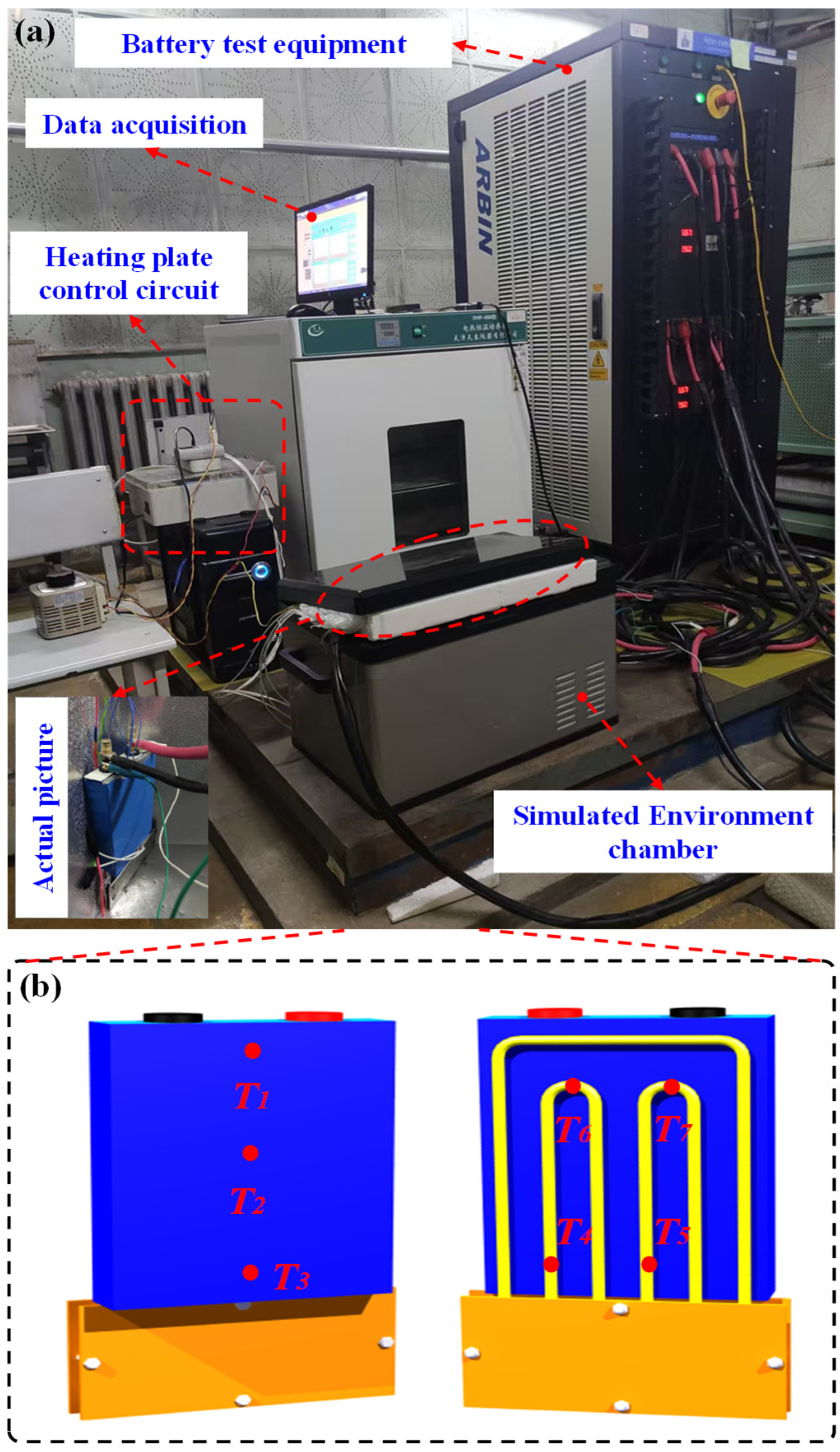
To conduct experimental research on the low-temperature performance of battery thermal management systems with pulsating heat pipes, a performance experimental platform was built using the developed pulsating heat pipe thermal management system as the test object, in conjunction with the battery comprehensive testing system, simulated environment chamber, and mica heating plate control circuit. The experimental platform consists of four parts: a battery comprehensive testing system, a simulated environment chamber, a pulsating heat pipe thermal management system (as described in detail in Section 2.3), and a low-temperature heating control circuit, as shown in Figure 3a.
(1)
Battery comprehensive testing system
The battery comprehensive testing system refers to the Arbin battery charge and discharge testing machine and the corresponding control software MITS Pro 2016. During the experiment, the pulsating heat pipe thermal management system containing a lithium battery was hard-wired to the Arbin battery charge (Texas, USA) and discharge testing machine through a charge and discharge cable. The corresponding MITS Pro software was used to set the charge and discharge status of the battery, including charge and discharge rate, charge and discharge cut-off conditions, and cycle charge and discharge.
(2)
Simulated environment chamber
An environment chamber refers to a freezer that provides a low-temperature environment, capable of providing a temperature of −30 °C with a temperature control accuracy of ± 1.0 °C and good insulation properties. During the experiment, simulate the low-temperature characteristics of the cold region where the battery is located.
(3)
Low-temperature heating control circuit
The mica heating element control circuit mainly includes three parts: information acquisition, heating control, and heating execution. The information acquisition module is responsible for recording and storing various parameters; The heating control module downloads the above thermal management strategy to the hardware control board to control its execution and sends control instructions (to control the mica heating element) to the heating execution module to achieve temperature regulation of the battery; The heating execution module includes a pulsating heat pipe, an aluminum homogenization plate, an aluminum collector plate, and mica heating plates. By adhering to the large side of the battery, the contact area between the heating execution and the large side of the battery is increased, making it easier to quickly heat the battery. During the experiment, the power of the mica heating plate was controlled by a corresponding control algorithm so that the heat generated by the heating element was transferred from the evaporation section of the pulsating heat pipe to the condensation section. The heat from the condensation section was evenly transferred to the surface of the battery through the aluminum homogenization plate. Signal acquisition utilizes temperature sensors to record temperature changes at different locations, using T 1 , T 2 , T 3 , T 4 , T 5 , T 6 and T 7 , respectively, with specific positions as shown in Figure 3b.

2.5. Performance Testing Projects

To investigate the performance of the pulsating heat pipe low-temperature thermal management system with different thermal management strategies, the following experimental projects were conducted.
(1)
Response of pulsating heat pipe low-temperature thermal management system under preheating conditions. The efficiency of the pulsating heat pipe thermal management system under preheating conditions is closely related to preheating power and environmental temperature. Generally speaking, for thermal management systems, it is necessary to match the system preheating power under different temperature conditions to ensure efficient operation of the system and achieve good preheating efficiency during the preheating stage.
(2)
The effectiveness of a pulsating heat pipe thermal management system with OECTMS in low-temperature discharge scenarios. The discharge scenario includes the preheating process and insulation process of the lithium battery. As mentioned earlier, OECTMS is to ensure that the battery operates within the allowable temperature range and reduce the system energy consumption caused by heating plates. This is achieved by using the fuzzy PID algorithm to control the power of the mica heating plates in real time. Therefore, it is necessary to explore the specific performance of the pulsating heat pipe thermal management system with OECTMS.
(3)
The effectiveness of a pulsating heat pipe thermal management system with OPTMS in low-temperature discharge scenarios. Similar to OECTMS, it also includes the preheating and insulation processes. OPTMS corresponds to the continuous operation of the heating plate, ensuring that the battery operates within the optimal temperature range and maximizes its performance. Therefore, it is necessary to explore the specific performance of the pulsating heat pipe thermal management system with OPTMS.
(4)
The effectiveness of a pulsating heat pipe thermal management system with OPTMS in low-temperature charging scenarios. Unlike discharge scenarios, low-temperature charging has a significant impact on the performance and lifespan of lithium batteries, and the role of thermal management systems is more prominent. Undoubtedly, the working temperature of lithium batteries should be raised as much as possible to reduce the negative impact of low-temperature environments. Therefore, OPTMS is preferred. Therefore, it is necessary to explore the specific performance of pulsating heat pipe thermal management systems with OPTMS in low-temperature charging scenarios.

3. Results and Discussion

3.1. Response of Pulsating Heat Pipe Thermal Management System Under Preheating Conditions

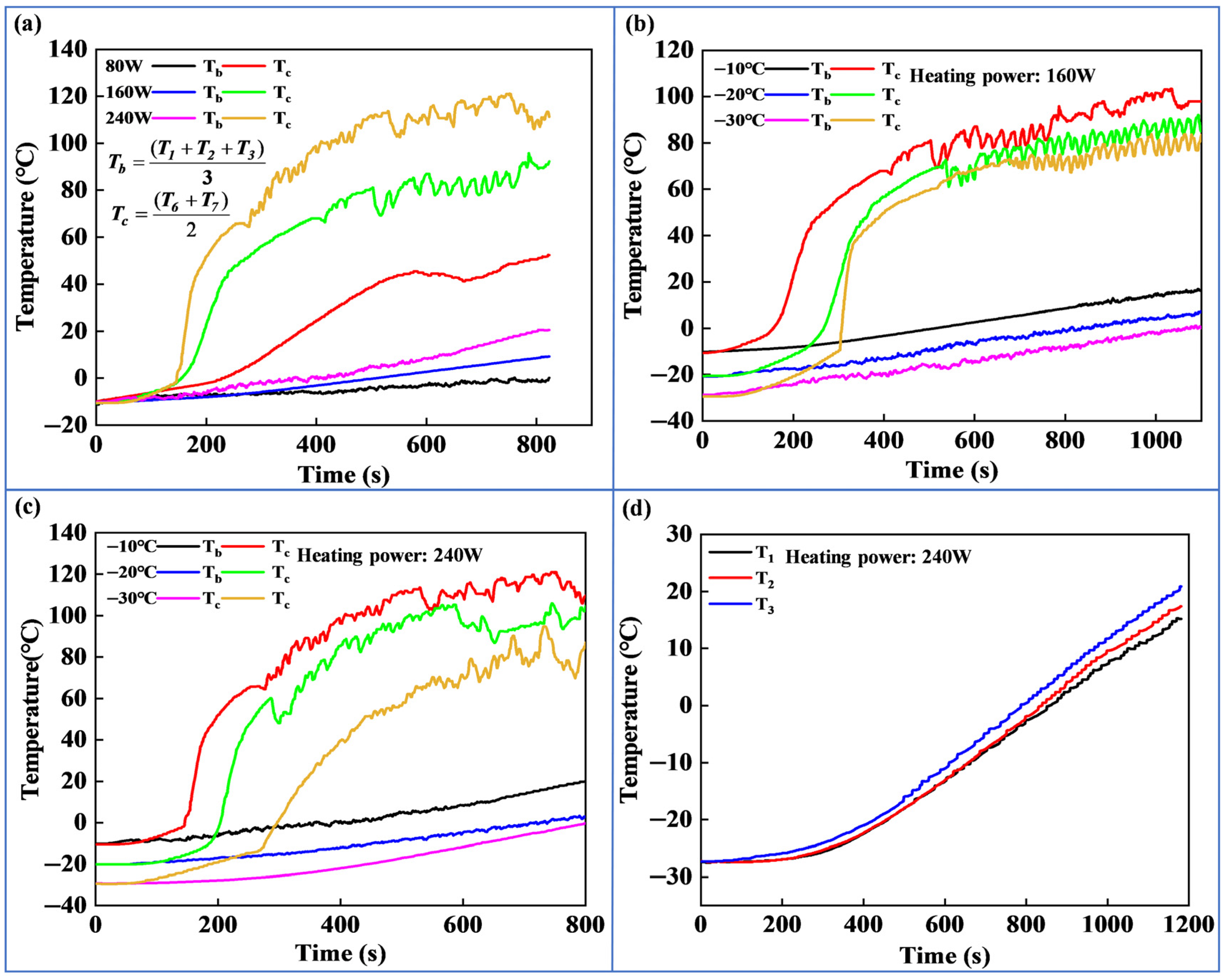
Figure 4a shows the average temperature changes in the battery and the pulsating heat pipe condensation section with different heating powers. It can be seen that the mica heating plate rapidly heats up and transfers heat to the pulsating heat pipe. The heat pipe starts and transfers heat through the evaporation section to the condensation section, further transferring heat to the battery for preheating. When heating the battery from −10 °C to 0 °C using different heating powers (80 W, 160 W, 240 W), the required times are 823 s, 513 s, and 419 s, respectively. Specifically, varying heating powers lead to different durations for raising the battery temperature from −10 °C to 0 °C. From these data, the battery’s temperature rise rates are calculated as 0.73 °C/min, 1.17 °C/min, and 1.43 °C/min, respectively. Based on the temperature rise rates, it can be concluded that a higher heating power supplied by the mica heating sheet results in a shorter heating time, a faster temperature rise rate of the lithium battery, and a more significant heating effect. Compared with the heating film-based method proposed by E et al. [42], which achieved a battery temperature rise rate of 1.18 °C/min, the liquid heating scheme developed by Sadar et al. [43] realized a battery temperature rise rate of 0.83 °C/min. This study, by utilizing the high thermal conductivity and pulsating heat transfer characteristics of the heat pipe, has gained significant advantages over the aforementioned schemes. When the input heating power increases, the time required for the pulsating heat pipe to start from low temperature is shortened, the condensation section of the heat pipe rapidly heats up, the heat pipe quickly reaches a stable heat transfer state, and the battery can obtain a higher temperature rise rate. Furthermore, as the heating power increases, the heating energy consumption also increases. When the heating power is 80 W, 160 W, and 240 W, the corresponding energy consumption is 18.2 Wh, 22.8 Wh, and 27.9 Wh, respectively. The preheating time of 240 W high power decreases, but the improvement of heating capacity is limited. According to Figure 4b, it can be seen that the time required to heat the surface temperature of the battery to 0 °C is 513 s, 841 s, and 1065 s at low temperatures of −10 °C, −20 °C, and −30 °C. And in Figure 4c, under the same conditions, the time required to heat the surface temperature of the battery to 0 °C is 419 s, 739 s, and 809 s, respectively. It can be seen that the heating time and temperature rise rate are greatly affected by the environment, and the preheating time of the battery is prolonged as the environmental temperature decreases.
Furthermore, when the environmental temperature is −30 °C and the heating power is 240 W, the temperature curves at different positions on the battery surface are shown in Figure 4d. The surface temperature of the battery with the pulsating heat pipe thermal management system shows a nonlinear rise. In the initial heating state, a certain delay in temperature rise is observed, and then the surface temperature of the battery begins to slowly rise. With further extension of heating time, the temperature curve shows a turning point at 250 s, and the temperature rise rate on the battery surface increases, which corresponds to the trend of temperature change in the condensation section of the pulsating heat pipe in Figure 4c. The main reason is that as the temperature of the evaporation section of the pulsating heat pipe increases, the heat pipe starts to start, and the working fluid inside the heat pipe begins to oscillate, accelerating the heat transfer of the heat pipe and causing the temperature of the condensation section to rise rapidly, thereby warming the battery and gradually increasing the surface temperature of the battery. Based on the above analysis, considering the high temperature at the condensation section of the heat pipe under high heating power, which is not conducive to the rapid and stable operation of the battery after preheating, 160 W is selected as the optimal preheating power for the battery.

3.2. Effectiveness of Pulsating Heat Pipe Thermal Management System with OECTMS in Low-Temperature Discharge

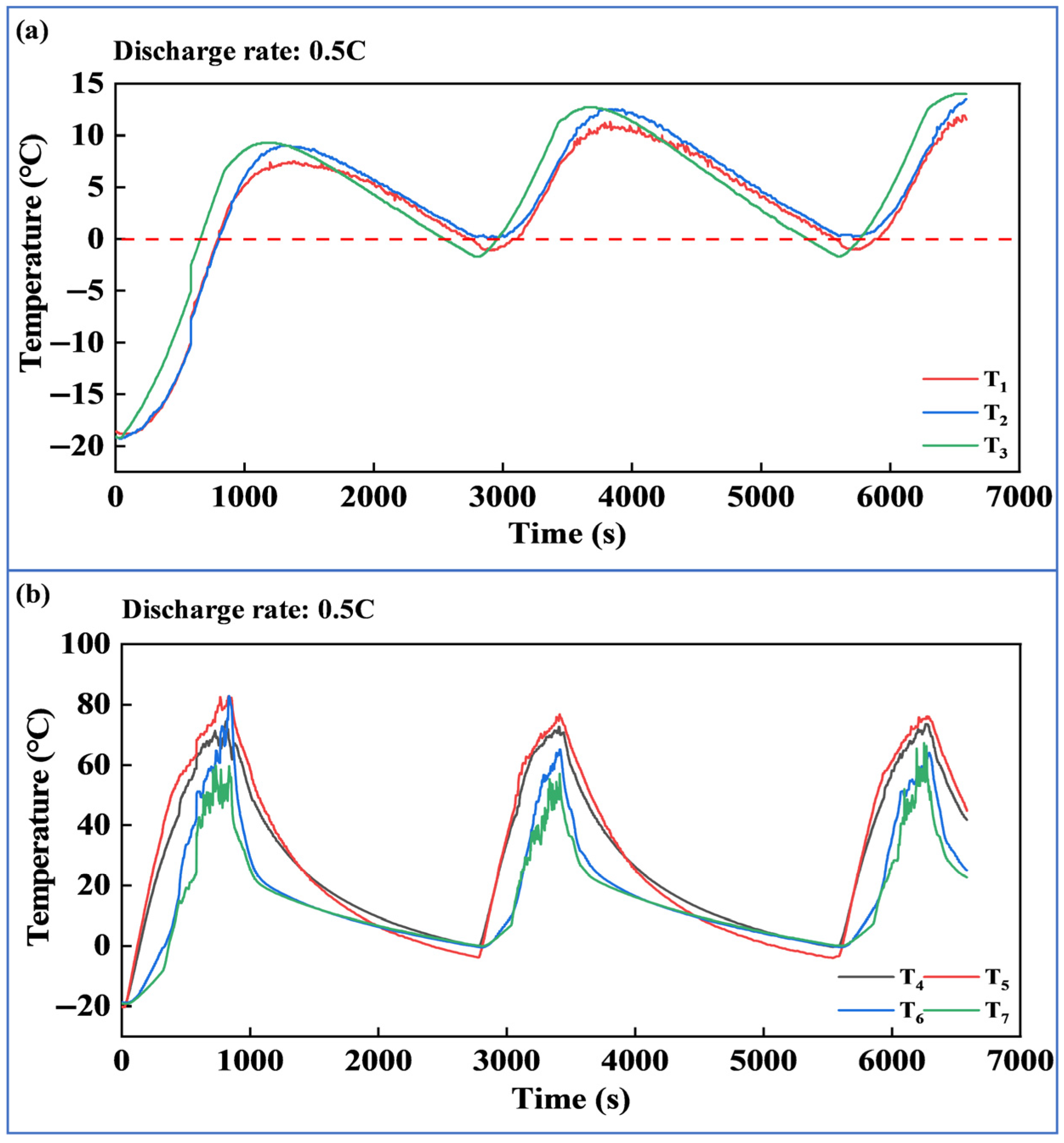
As mentioned earlier, the low-temperature discharge scenario includes the preheating and insulation process of the lithium battery. Relying solely on preheating, the temperature of the lithium battery will continue to decrease, and it is difficult to maintain its temperature above 0 °C in low temperatures. This indicates that preheating alone cannot guarantee the performance of the battery. OECTMS can achieve continuous operation of the lithium battery above 0 °C. Figure 5a,b show the surface temperature variation in the lithium battery and pulsating heat pipes. By adopting the OECTMS, the surface temperature rise in the battery shows three peaks. After preheating the battery to 0 °C, it can be concluded that during the battery discharge process, there are two times when the temperature drops below 0 °C, and the battery is heated to 0 °C. However, due to the residual heat generated by the heat pipe heating, there is a significant temperature surge phenomenon in the battery and the heat pipe. Nevertheless, the overall temperature variation in the lithium battery exhibits strong consistency. At the same stage, the overall temperature of the battery is very uniform, and the thermal environment is good.
Furthermore, Table 5 presents the discharge capacity data of the lithium battery with OECTMS. Under low temperatures of −10 °C, −20 °C, and −30 °C, the discharge capacities of the lithium battery under individual preheating are 56.38 Ah, 50.88 Ah, and 46.62 Ah, respectively. The capacity of the lithium battery with OECTMS reached 60.06 Ah, 54.76 Ah, and 48.66 Ah, respectively. Compared with a battery without a thermal management system (TMS), the discharge capacity increased by 10.67%, 14.11%, and 29.83%. Undoubtedly, intermittent heating of the lithium battery through OECTMS can significantly improve battery discharge capacity.

3.3. Effectiveness of Pulsating Heat Pipe Thermal Management System with OPTMS in Low-Temperature Discharge

The above discussed the temperature and discharge capacity changes in the lithium battery with OECTMS. Intermittent heating of the lithium battery has improved its low-temperature performance to a certain extent, but the pulsating heat pipe start-up has a certain delay, and the residual heat during the heating process of the heat pipe causes the surface temperature of the battery to overshoot. Therefore, to ensure long-term temperature stability of the pulsating heat pipe and eliminate the adverse factors caused by repeated start-up of the heat pipe, it is necessary to examine the pulsating heat pipe thermal management performance with OPTMS. OPTMS ensures that the lithium battery operates within the optimal temperature range and maximizes its performance by continuously using mica heating plates.
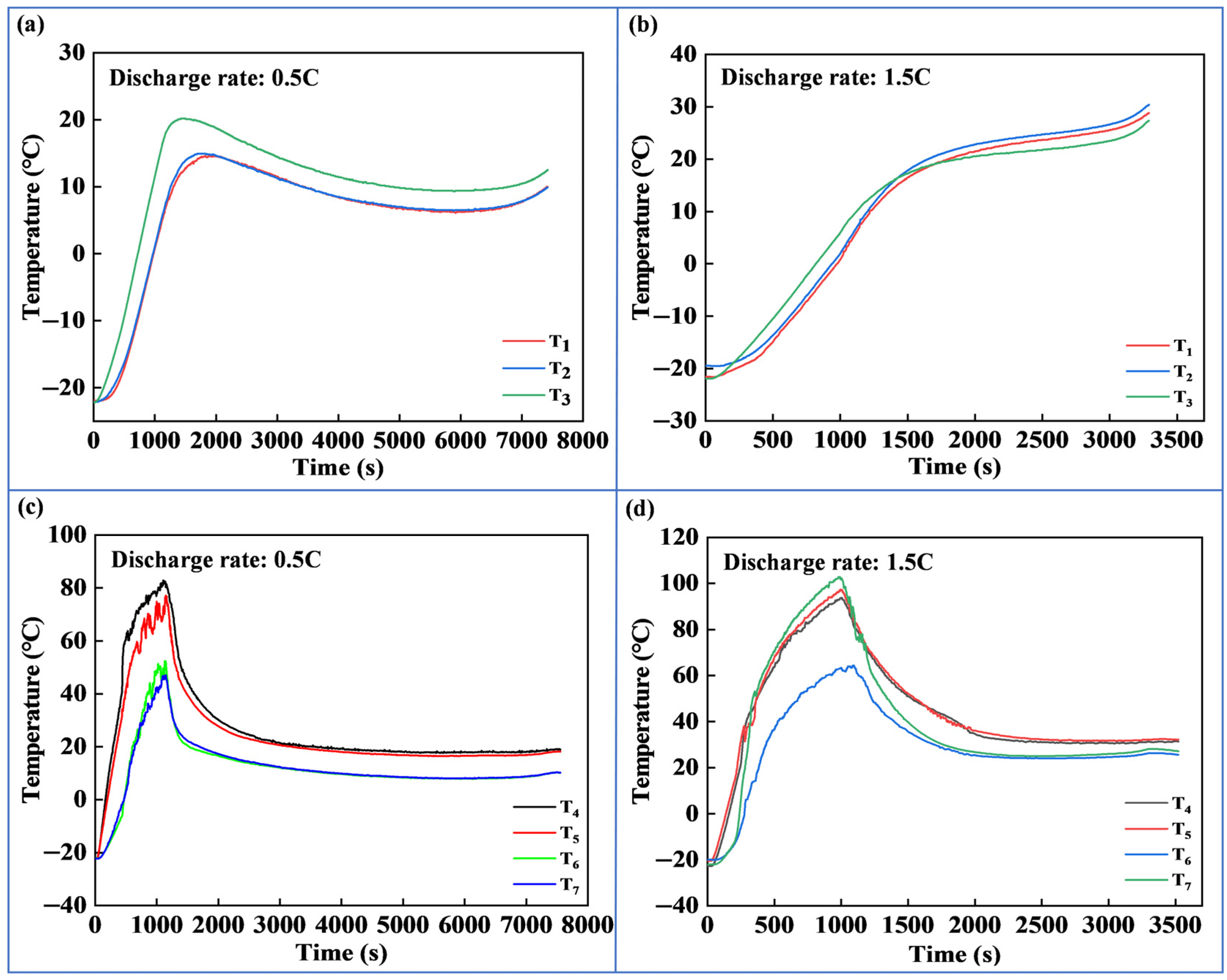
As shown in Figure 6, data on surface temperature and pulsating heat pipe temperature changes in the lithium battery with OPTMS under a low temperature of −20 °C at discharge rates of 0.5C and 1.5C were recorded. The battery temperature was always maintained above 0 °C, and the temperature changed steadily during the complete discharge process without significant temperature surges. Therefore, the pulsating heat pipe thermal management system with OPTMS continuously heats the battery, resulting in a significant increase in the surface temperature of the battery.
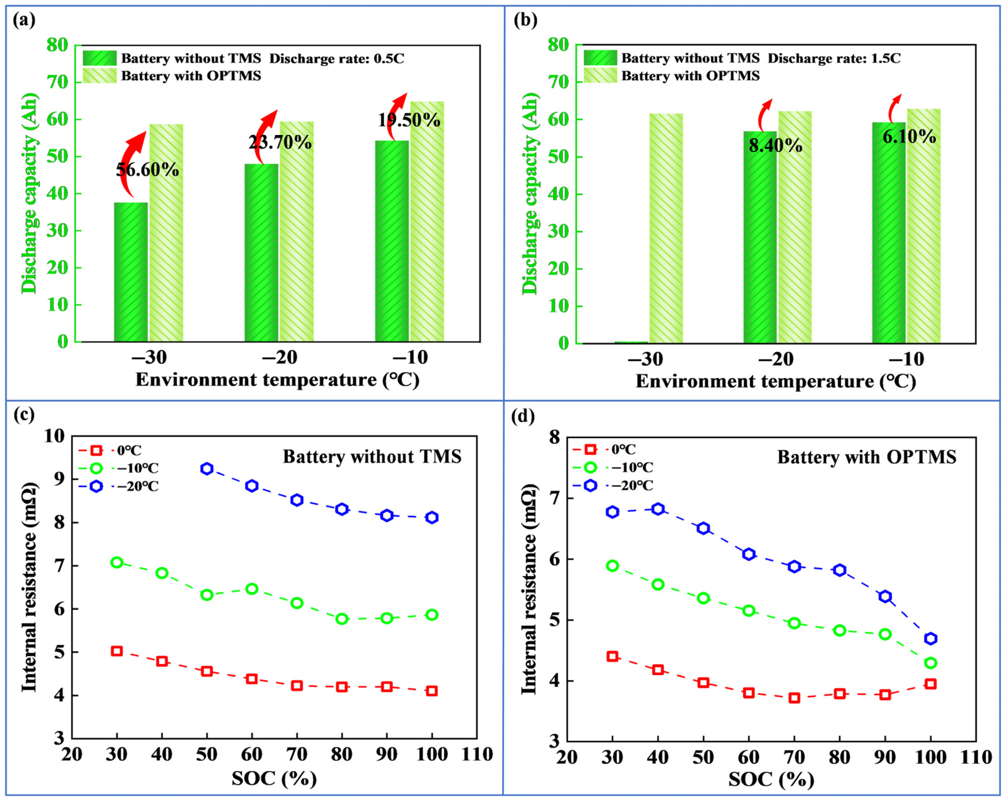
Figure 7a,b show the corresponding discharge capacity data. At a discharge rate of 0.5C, the discharge capacities of the lithium battery reached 64.83 Ah, 59.41 Ah, and 58.69 Ah, respectively. However, the capacities corresponding to the battery without TMS are 37.48 Ah, 47.99 Ah, and 54.27 Ah. Compared with a battery without TMS, the discharge capacities increased by 19.5%, 23.7%, and 56.6% in low temperatures of −10 °C, −20 °C, and −30 °C. Especially at a discharge rate of 1.5C, the battery without TMS cannot be discharged at −30 °C; the discharge capacity of the battery with OPTMS is increased to 61.55 Ah. Figure 7c shows the discharge internal resistance of the battery without TMS under different temperature conditions, while Figure 7d shows the corresponding discharge internal resistance of the battery with OPTMS. The comparison shows that the internal resistance of the battery in a low-temperature environment is the main factor that reduces battery performance. By continuously warming the battery with the OPTMS, the internal resistance of the battery decreases significantly, which improves the discharge performance of the battery to a certain extent and eliminates the adverse effects of low temperature on the battery, thereby improving the overall working environment of the battery.

3.4. Effectiveness of Pulsating Heat Pipe Thermal Management System with OPTMS in Low-Temperature Charge

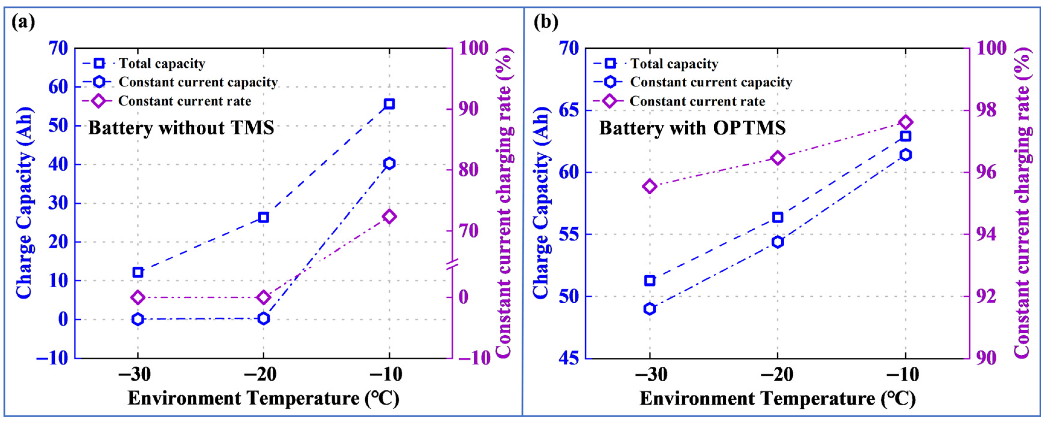
As mentioned earlier, the lithium battery has achieved good thermal performance and significantly improved discharge capacity with OPTMS in the low-temperature discharge scenario. Undoubtedly, adopting OPTMS in low-temperature charging scenarios results in overall temperature changes in the lithium battery similar to those of discharge scenarios. Unlike low-temperature discharge scenarios, low-temperature charging scenarios have a direct impact on the charging efficiency of the lithium battery. Here, the focus is on examining the low-temperature efficiency characteristics of the lithium battery with OPTMS. Charging efficiency can generally be characterized by parameters such as charging capacity, constant current charging capacity, and constant current charging rate.
As shown in Figure 8, the study investigates the charging performance of the lithium battery with OPTMS under different low temperatures at a 1.0C rate. The battery can achieve constant current charging at temperatures of −10 °C, −20 °C and −30 °C. Meantime, the constant current charging time is greatly improved, and the proportion of constant current charging capacity increases. After constant current and constant voltage charging, the capacities are 62.91 Ah, 56.38 Ah, and 51.28 Ah, respectively. On the other hand, lithium batteries without TMS have cumulative charging capacities of 55.64 Ah, 26.38 Ah, and 12.16 Ah; the charging capacity has significantly decreased. Further observation of its constant current charging capacity shows that there is almost no constant current charging stage under the environmental temperature of −20 °C and −30 °C. Even if the lithium battery is charged with a certain amount of electricity, this is achieved at the expense of charging time during the constant voltage stage, which is intolerable for the charging efficiency of the lithium battery and does not meet the development needs of fast charging technology. Observing Figure 8b, with the pulsating heat pipe low-temperature thermal management system, the transverse constant current charging rate of the lithium battery under different environmental temperature conditions is not less than 95.55%, the constant current charging time is significantly improved, and the charging efficiency is significantly improved. (Here, the value of 95.55% refers to the ratio of the capacity charged into the lithium battery during the constant current charging stage to the total charged capacity. A larger value of this ratio indicates a higher proportion of the constant current charging stage in the entire charging process and thus a higher charging efficiency of the lithium battery.) Upon investigation, the heating effect of the pulsating heat pipe improves the environment for internal electrochemical reactions in the lithium battery, enhances the activity of battery materials, reduces the difficulty of Li + diffusion through electrode materials, and enables the normal progress of lithium ion deintercalation reactions.
As previously stated, the OPTMS enables superior thermal performance and electrical performance of the battery, which is achieved through preheating and heat preservation. It is necessary to focus on the “benefits” derived from the energy released by the battery with the OPTMS and the “costs” caused by the additional energy consumption for preheating and heat preservation. This can be expressed as follows:
φ = ( E o p t m s E b ) E t m s ( E o p t m s E b ) E t m s = P o p × T o p
where E t m s represents the energy consumption for heating battery (kWh); E o p t m s represents the charging energy under the OPTMS (kWh); E b represents the charging energy of the bare without TMS (kWh); P o p represents the heating power (kW); T o p represents the heating time (h). It can be seen from the above formula that the additional energy released by the battery is subtracted from the heating energy consumption. This clearly reflects the balance between energy “benefits” and “costs” and indicates the energy consumption of the heating system. Furthermore, this difference is divided by the additional energy released by the battery. A larger ratio indicates that more energy remains from the additional energy released by the battery after deducting the heating energy consumption. As shown in Table 6, this value is negative at an ambient temperature of −10 °C. The main reason is that there is no significant difference in the final charged capacity. As indicated in the previous analysis, the charging capacities of the battery without TMS under different low temperatures are 55.64 Ah, 26.38 Ah, and 12.16 Ah, respectively, whereas the charging capacities of the battery with OPTMS are 62.92 Ah, 56.38 Ah, and 51.28 Ah, respectively. Therefore, the energy benefit obtained is limited, while the energy consumption for preheating and heat preservation does not decrease, resulting in a relatively poor value from the theoretical calculation. At −20 °C and −30 °C, the OPTMS achieves positive economic efficiency and brings considerable benefits, with the corresponding values of 52.35% and 58.02%, respectively. In fact, the above analysis also provides new insights, such as adopting different heating strategies for different low-temperature ranges.

4. Conclusions

This paper introduces pulsating heat pipe technology and proposes a novel pulsating heat pipe thermal management scheme. The optimal energy consumption and optimal performance thermal management strategies are proposed, and corresponding performance test benches are built. Performance experiments of pulsating heat pipe thermal management systems are conducted in different low-temperature scenarios. The specific conclusions are as follows:
(1)
Response of the PHP Heating System Under Preheating Conditions. Under different low-temperature conditions, a comparison of different heating powers reveals that a higher heating power results in a shorter heating time and a faster temperature rise rate of the battery. However, an excessively high heating power does not further increase the battery’s temperature rise rate; instead, it leads to a sharp increase in heating energy consumption. Selecting a heating power of 160 W can achieve an effective balance between heating time and heating energy consumption.
(2)
Heating efficacy of the PHP heating system with the OECTMS in discharge scenarios. Compared with a battery without TMS, the OECTMS significantly improves the discharge capability of the battery, with the battery capacity increasing by 10.67%, 14.11%, and 29.83%, respectively. However, the intermittent insulation method adopted causes the temperature to be in a dynamic fluctuation state, with obvious peaks, valleys, and temperature spikes. Nevertheless, this does not impair the overall consistency of the battery’s temperature changes.
(3)
Heating efficacy of the PHP heating system with the OPTMS in discharge scenarios. The greatest advantage of the OPTMS lies in maintaining the battery temperature above 0 °C at all times. It eliminates temperature peaks, valleys, and spikes of the battery, thereby achieving a significant improvement in the thermal performance. Meanwhile, this strategy further enhances the discharge capacity. Compared with the battery without TMS, the discharge capacities at 0.5C rate are increased by 19.5%, 23.7%, and 56.6%, respectively. At the 1.5C rate, it enables the battery—originally unable to discharge—to achieve a discharge capacity of 61.55 Ah. Compared with the OECTMS, the discharge capacity is increased by 7.94%, 8.49%, and 20.61%, respectively. There is no doubt that both the thermal and electrical performance of the battery with the OPTMS are improved.
(4)
Heating efficacy of the PHP heating system with the OPTMS in charging scenarios. The OPTMS ensures that the battery achieves excellent thermal performance in low temperatures, which significantly improves the low-temperature charging performance. Specifically, it enables the constant-current charging ratio of the battery to exceed 95.55% across different low-temperature conditions. Compared with a battery without TMS, the charging capacity with this strategy increases by 321.71%, 113.72%, and 13.07%, respectively. Meanwhile, the charging efficiency achieves an order-of-magnitude improvement. In contrast, for a battery without TMS, the electrical energy stored during charging is obtained at the cost of extended charging time in the constant-voltage stage.
This study introduces pulsating heat pipe technology, providing new insights for the low-temperature heating of batteries. Its advantages lie in making full use of the thermal conductivity, pulsating heat transfer characteristics of the pulsating heat pipe, and the large-area heating scheme, which has yielded favorable experimental results. Regrettably, the current research has only conducted experimental verification on a single battery. In the future, the research can be further extended to battery modules to further prove the feasibility and efficiency of this method.

Author Contributions

Conceptualization, methodology, software, validation, investigation, data curation, writing—original draft preparation, writing—review and editing, visualization, supervision, and project administration, K.L. and X.W. All authors have read and agreed to the published version of the manuscript.

Funding

This research received no external funding.

Data Availability Statement

The data presented in this study are available on request from the corresponding author.

Acknowledgments

The authors have reviewed and edited the output and take full responsibility for the content of this publication.

Conflicts of Interest

The authors declare no conflicts of interest.

Abbreviations

The following abbreviations are used in this manuscript:
EVsElectric vehicles
OECTMSOptimal energy consumption thermal management strategies
OPTMSOptimal performance thermal management strategies

References

  1. Fang, J.; Yin, X.; Guan, J.; Han, X.; Jia, F.; Chen, B.; Cao, F.; Wang, X. Comparative study on the thermal performance of the battery two-phase direct CO2 cooling system with parallel and half-series configuration for electric vehicles. Renew. Energy 2025, 242, 122461. [Google Scholar] [CrossRef]
  2. Zeng, X.; Li, J.; Qiao, L.; Chen, M. Experimental study on the performance of power battery module heating management under a low–temperature charging scenario. Int. J. Heat Mass Transf. 2024, 225, 125388. [Google Scholar] [CrossRef]
  3. Yetik, O.; Engün, S.; Kok, B.; Karakoc, T.H. Thermal management system of batteries using AlN reinforced TPMS–PCM composite material. Energy 2024, 313, 134137. [Google Scholar] [CrossRef]
  4. Close, J.; Barnard, J.E.; Chew, Y.J.; Perera, S. A holistic approach to improving safety for battery energy storage systems. J. Energy Chem. 2024, 92, 422–439. [Google Scholar] [CrossRef]
  5. Amer, M.M.; Shouman, M.A.; Salem, M.S.; Kannan, A.M.; Hamed, A.M. Advances in thermal management systems for Li-Ion batteries: A review. Therm. Sci. Eng. Prog. 2024, 53, 102714. [Google Scholar] [CrossRef]
  6. Wang, Y.; Wang, Y.; He, T.; Mao, N. A numerical study on a hybrid battery thermal management system based on PCM and wavy microchannel liquid cooling. Renew. Energy 2024, 235, 121273. [Google Scholar] [CrossRef]
  7. Sungur, B.; Kaleli, A. Experimental investigation of lithium-ion battery cell heating under subzero conditions using induction-based liquid and internal DC heating. J. Energy Storage 2025, 133, 118014. [Google Scholar] [CrossRef]
  8. Vu, H.; Shin, D. Simultaneous internal heating for balanced temperature and state-of-charge distribution in lithium-ion battery packs. J. Energy Storage 2023, 60, 106519. [Google Scholar] [CrossRef]
  9. Ruan, H.; Jiang, J.; Sun, B.; Zhan, W.; Gao, W.; Wang, L.Y.; Ma, Z. A rapid low-temperature internal heating strategy with optimal frequency based on constant polarization voltage for lithium-ion batteries. Appl. Energy 2016, 177, 771–782. [Google Scholar] [CrossRef]
  10. Li, J.-Q.; Fang, L.; Shi, W.; Jin, X. Layered thermal model with sinusoidal alternate current for cylindrical lithium-ion battery at low temperature. Energy 2018, 148, 247–257. [Google Scholar] [CrossRef]
  11. Guo, S.; Xiong, R.; Wang, K.; Sun, F. A novel echelon internal heating strategy of cold batteries for all-climate electric vehicles application. Appl. Energy 2018, 219, 256–263. [Google Scholar] [CrossRef]
  12. Ge, H.; Huang, J.; Zhang, J.; Li, Z. Temperature-Adaptive Alternating Current Preheating of Lithium-Ion Batteries with Lithium Deposition Prevention. Electrochem. Soc. 2016, 163, 290–299. [Google Scholar] [CrossRef]
  13. Jiang, J.; Ruan, H.; Sun, B.; Wang, L.; Gao, W.; Zhang, W. A low-temperature internal heating strategy without lifetime reduction for large-size automotive lithium-ion battery pack. Appl. Energy 2018, 230, 257–266. [Google Scholar] [CrossRef]
  14. Ouyang, D.; Huang, J.; Zheng, Y.; Wang, Z. Numerical simulation and analysis of the effect of charging and discharging on the thermal runaway of lithium-ion batteries under external heating conditions. Appl. Therm. Eng. 2025, 274, 126616. [Google Scholar] [CrossRef]
  15. Marri, G.K.; Ee, Y.J.; He, Z.; Ho, J.Y. Recent advancements in internal and external thermoregulation strategies for lithium-ion batteries. Renew. Sustain. Energy Rev. 2026, 225, 116127. [Google Scholar] [CrossRef]
  16. Liu, X.; Li, Y.; Gao, S.; Zhou, Z.; Wu, W.-T.; Wei, L.; Lyu, J.; Li, Y.; Song, Y. Efficient cold-starting project with mild lithium plating for lithium-ion batteries using immersion liquid cooling at low temperatures. Appl. Energy 2025, 384, 125510. [Google Scholar] [CrossRef]
  17. Zhang, H.; Zhao, Y.; Tian, Y.; Zhang, Y.; Tao, Z.; Xu, S. Multi-level optimization of low-temperature heating methods for large-capacity lithium-ion batteries based on temperature uniformity. Energy 2025, 330, 136628. [Google Scholar] [CrossRef]
  18. Zhong, R.; Feng, W.; Ma, Y.; Deng, J.; Liu, Y.; Ding, S.; Wang, X.; Liang, Y.; Yang, G. Experimental study of heat pipe start-up characteristics and development of an enhanced model considering gas diffusion effects. Appl. Therm. Eng. 2024, 257, 124460. [Google Scholar] [CrossRef]
  19. Liu, K.; Shi, B.; Zhang, P. Heat transfer characteristics of ultrathin heat pipe considering unsaturated wick at different filling rates. Int. J. Heat Mass Transf. 2024, 235, 126195. [Google Scholar] [CrossRef]
  20. Li, Y.; Guo, H.; Qi, F.; Guo, Z.; Li, M. Lina Bertling Tjernberg. Investigation on liquid cold plate thermal management system with heat pipes for LiFePO4 battery pack in electric vehicles. Appl. Therm. Eng. 2021, 185, 116382. [Google Scholar] [CrossRef]
  21. Mbulu, H.; Laoonual, Y.; Wongwises, S. Experimental study on the thermal performance of a battery thermal management system using heat pipes. Case Stud. Therm. Eng. 2021, 26, 101029. [Google Scholar] [CrossRef]
  22. Abbas, S.; Ramadan, Z.; Park, C.W. Thermal performance analysis of compact-type simulative battery module with paraffin as phase-change material and flat plate heat pipe. Int. J. Heat Mass Transf. 2021, 173, 121269. [Google Scholar] [CrossRef]
  23. He, L.; Tang, X.; Luo, Q.; Liao, Y.; Luo, X.; Liu, J.; Ma, L.; Dong, D.; Gan, Y.; Li, Y. Structure optimization of a heat pipe-cooling battery thermal management system based on fuzzy grey relational analysis. Int. J. Heat Mass Transf. 2022, 182, 121924. [Google Scholar] [CrossRef]
  24. Liang, Z.; Wang, R.; Malt, A.H.; Souri, M.; Esfahani, M.N.; Jabbari, M. Systematic evaluation of a flat-heat-pipe-based thermal management: Cell-to-cell variations and battery ageing. Appl. Therm. Eng. 2021, 192, 116934. [Google Scholar] [CrossRef]
  25. Nazari, M.A.; Mohammad, H. Ahmadi, Roghayeh Ghasempour, Mohammad Behshad Shafii, Omid Mahian, Soteris Kalogirou, Somchai Wongwises. A review on pulsating heat pipes: From solar to cryogenic applications. Appl. Energy 2018, 222, 475–484. [Google Scholar] [CrossRef]
  26. Yang, L.; Du, K. A comprehensive review on heat transfer characteristics of TiO2 Nanofluids. Int. J. Heat Mass Transf. 2017, 108, 11–31. [Google Scholar] [CrossRef]
  27. Chen, M.; Li, J. Experimental study on heating performance of pure electric vehicle power battery under low temperature environment. Int. J. Heat Mass Transf. 2021, 172, 121191. [Google Scholar] [CrossRef]
  28. Bahiraei, F. A pseudo 3D electrochemical-thermal modeling and analysis of a lithium-ion battery for electric vehicle thermal management applications. Appl. Therm. Eng. 2017, 125, 904–918. [Google Scholar] [CrossRef]
  29. Kesong, L.; Moyuan, C.; Akira, F.; Lei, J. Bio-inspire titanium dioxide materials with special wettability and their applications. Chem. Reviews 2014, 114, 10044–10094. [Google Scholar]
  30. Islam, M.R.; Shabani, B.; Rosengarten, G. Electrical and Thermal Conductivities of 50/50 Water-ethylene Glycol Based TiO2 Nanofluids to be Used as Coolants in PEM Fuel Cells. Energy Procedia 2017, 110, 101–108. [Google Scholar] [CrossRef]
  31. Madheswaran, D.K.; Vengatesan, S.; Varuvel, E.G.; Praveenkumar, T.; Jegadheeswaran, S.; Pugazhendhi, A.; Arulmozhivarman, J. Nanofluids as a coolant for polymer electrolyte membrane fuel cells: Recent trends, challenges, and future perspectives. J. Clean. Prod. 2023, 424, 138763. [Google Scholar] [CrossRef]
  32. Cavieres-Garrido, F.; Martínez, V.A.; Núñez-Aedo, J.; Chen, D.; Vasco, D.A. Experimental study of the heat transfer during the ice formation of TiO2 water-nanofluid around a helical coil CTES system. Appl. Therm. Eng. 2023, 230, 120829. [Google Scholar] [CrossRef]
  33. Wei, Y.; Tao, Y.; Lin, Y.; Feng, Y.; Chu, F. Evaporation dynamics and deposition patterns of ethanol-based Al2O3 nanofluid droplets: Effects of particle sizes and substrate temperatures. Colloids Surf. A Physicochem. Eng. Asp. 2025, 719, 137040. [Google Scholar] [CrossRef]
  34. Zhang, L.; Song, J.; Qu, P.; Wang, S.; Zhang, H.; Wang, H.; Liu, H.; Lu, T. Heat transfer performance study of Cu-ethanol/ethylene glycol/propylene glycol-water nanofluids in a wavy-walled tube heat exchanger. J. Environ. Chem. Eng. 2024, 12, 112738. [Google Scholar] [CrossRef]
  35. Duan, Z.; Hong, X.; Li, H.; Ruan, D. Simulating the uneven temperature distributions within large-sized lithium-ion batteries using a thermal resistance network model. J. Energy Storage 2024, 101, 113732. [Google Scholar] [CrossRef]
  36. Smith, J.; Singh, R. Battery thermal management system for electric vehicle using heat pipes. Int. J. Therm. Sci. 2018, 134, 517–529. [Google Scholar] [CrossRef]
  37. Fourgeaud, L.; Nikolayev, V.S.; Ercolani, E.; Duplat, J.; Gully, P. In situ investigation of liquid films in pulsating heat pipe. Appl. Therm. Eng. 2017, 126, 1023–1028. [Google Scholar] [CrossRef]
  38. Zhang, Y.W.; Faghri, A. Advances and unsolved issues in pulsating heat pipes. Heat Transf. Eng. 2008, 29, 20–44. [Google Scholar] [CrossRef]
  39. Qu, J.; Wu, H.; Cheng, P. Start-up heat transfer and flow characteristics of silicon-based micro pulsating heat pipes. Int. J. Heat Mass Transf. 2012, 55, 09–20. [Google Scholar] [CrossRef]
  40. Pang, H.; Leng, Y.; Nan, W.; Jiang, N.; Du, J. Intelligent equalization control for lithium-ion battery packs in electric vehicles: A multi-variable cooperative equalization controller based on dual-variable fuzzy PID. Sustain. Energy Technol. Assess. 2025, 82, 104508. [Google Scholar] [CrossRef]
  41. Tian, W.; Zhang, X.; Luo, Y.; Ding, Z.; Liu, Z. Lithium battery model parameter online estimation in hybrid electric UAVs with fuzzy rolling convex optimization method. J. Energy Storage 2025, 132, 117928. [Google Scholar] [CrossRef]
  42. E, J.; Qin, Y.; Zhang, B.; Yin, H.; Tan, Y. Effects of heating film and phase change material on preheating performance of the lithium-ion battery pack with large capacity under low temperature environment. Energy 2023, 284, 129280. [Google Scholar] [CrossRef]
  43. Sadar, A.; Amir, M.; Mohammad, N. An optimal design of battery thermal management system with advanced heating and cooling control mechanism for lithium-ion storage packs in electric vehicles. J. Energy Storage 2024, 99, 113421. [Google Scholar] [CrossRef]
Figure 1. Pulsating heat pipe thermal management system for low-temperature.
Wevj 16 00597 g001
Figure 2. Control logic diagram of fuzzy PID controller.
Wevj 16 00597 g002
Figure 3. Low temperature performance testing bench. (a) experimental diagram of pulsating heat pipe thermal management system; (b) schematic diagram of sensor location.
Wevj 16 00597 g003
Figure 4. The average temperature of the battery and the pulsating heat pipe condensation section. (a) Battery temperature and heat pipe condensation section temperature under different heating power; (b) battery temperature and heat pipe condensation section temperature at a heating power of 160 W; (c) battery temperature and heat pipe condensation section temperature at a heating power of 240 W; (d) battery surface temperature at a heating power of 240 W.
Wevj 16 00597 g004
Figure 5. Temperature variation in the lithium battery and the pulsating heat pipe under the OECTMS. (a) Battery temperature variation; (b) pulsating heat pipe surface temperature variation.
Wevj 16 00597 g005
Figure 6. Temperature variation in the lithium battery and the pulsating heat pipe corresponding to OPTMS. (a) Battery temperature variation at 0.5C discharge rate; (b) battery temperature variation at 1.5C discharge rate; (c) pulsating heat pipe surface temperature variation at 0.5C discharge rate; (d) pulsating heat pipe surface temperature variation at 1.5C discharge rate.
Wevj 16 00597 g006
Figure 7. Discharge capacity and internal resistance of battery with OPTMS. (a) Battery discharge capacity at 0.5C discharge rate; (b) battery discharge capacity at 1.5C discharge rate; (c) discharge internal resistance of the battery without TMS at different temperatures; (d) discharge internal resistance of the battery with OPTMS at different temperatures.
Wevj 16 00597 g007
Figure 8. Charging capacity and constant current charging capacity rate of the battery with OPTMS. (a) battery without TMS; (b) battery with OPTMS.
Wevj 16 00597 g008
Table 1. Relevant parameters.
ItemsParametersValue
Lithium batteryMass (kg)1.4
Capacity (Ah)68
Size (mm)135.5 × 29.3 × 185.3
Rated voltage (V)3.2
Charging cutoff voltage (V)3.65
Discharging cutoff voltage (V)2.5
Maximum charging current (C)1
Maximum discharging current (C)2
Operating temperature (°C)−30~55
Heating plateElectric strength (V/min·mA)1500/1·5
Operating temperature (°C)−150–600
Power density (W/cm2)17
Power deviation (%)±5
Recession time (h)20,000
Pulsating heat pipePipe materialCopper
Cross-sectionsCircle
Number of turns5
Evaporation section length (mm)45
Condensation section length (mm)183
Total length (mm)228
Total width (mm)115
Inner diameter (mm)5
Table 2. Fuzzy control rule of Δ k p .
Δ k p e
MLMIMPZOFPFIFL
e c MLFLFLFIFIFPZOZO
MIFLFLFIFPFPZOMP
MPFIFIFIFPZOMPMP
ZOFIFIFPZOMPMIMI
FPFPFPZOMPMPMIMI
FIFPZOMPMIMIMIML
FLZOZOMIMIMIMLML
Table 3. Fuzzy control rule of Δ k i .
Δ k i e
MLMIMPZOFPFIFL
e c MLMLMLMIMIMPZOZO
MIMLMLMIMPMPZOZO
MPMLMIMPMPZOFPFP
ZOMIMIMPZOFPFIFI
FPMIMPZOFPFPFIFL
FIZOZOFPFPFPFIFL
FLZOZOFPFIFIFLFL
Table 4. Fuzzy control rule of Δ k d .
Δ k d e
MLMIMPZOFPFIFL
e c MLFPMPMLMLMLMIFP
MIFPMPMLMIMIMPZO
MPZOMPMIMIMPMPZO
ZOZOMPMPMPMPMPZO
FPZOZOZOZOZOZOZO
FIFLMPFPFPFPFPFL
FLFLFIFIFIFIFPFL
Table 5. Discharge capacity of lithium battery with OECTMS in low-temperature discharge.
ItemsEnvironmental Temperature
−10 °C−20 °C−30 °C
Battery without TMS54.2747.9937.48
Battery with preheating56.3850.8846.62
Battery with OECTMS60.0654.7648.66
Increase rate (Battery without TMS vs. Battery with OECTMS)10.67%14.11%29.83%
Table 6. Economic analysis.
Charge RateEnvironmental Temperature
−10 °C−20 °C−30 °C
1.0C−14.69%52.35%58.02%
Disclaimer/Publisher’s Note: The statements, opinions and data contained in all publications are solely those of the individual author(s) and contributor(s) and not of MDPI and/or the editor(s). MDPI and/or the editor(s) disclaim responsibility for any injury to people or property resulting from any ideas, methods, instructions or products referred to in the content.