Article

Position Sensorless Control of BLDCM Fed by FSTP Inverter with Capacitor Voltage Compensation

1
Weichai Power Co., Ltd., Weifang 261061, China
2
State Key Laboratory of Engine and Powertrain System, Weifang 261061, China
3
Advanced Electrical Equipment Innovation Center, Zhejiang University, Hangzhou 311107, China
*
Author to whom correspondence should be addressed.
World Electr. Veh. J. 2025, 16(10), 582; https://doi.org/10.3390/wevj16100582
Submission received: 1 August 2025 / Revised: 22 September 2025 / Accepted: 10 October 2025 / Published: 15 October 2025
(This article belongs to the Special Issue Vehicle Control and Drive Systems for Electric Vehicles)

Abstract

Aiming at the commutation error in position sensorless control of brushless DC motors (BLDCMs) driven by four-switch three-phase (FSTP) inverters—caused by ignoring capacitor voltage fluctuations—this paper proposes a novel position sensorless control method based on voltage offset compensation. By independently performing PWM modulation on the switches of the non-capacitor-connected phases (Phase a and Phase b), the method suppresses three-phase current distortion. Meanwhile, it calculates the terminal voltages using switch signals and constructs a G(θ) function independent of the motor speed. Based on the voltage compensation amount derived in this paper, the influence of capacitor voltage fluctuations on this function is compensated. According to the relationship between the extreme value jump edges of the G(θ) function (after voltage compensation) and the commutation points, the accurate commutation signals required for motor operation are determined. The proposed strategy eliminates the need for filters, which not only avoids phase delay but also is suitable for motor rotor position estimation over a wider speed range. Experimental results show that compared with the uncompensated method, the average commutation error is reduced from approximately 18° to less than 3° electrical angle. Under different operating conditions, the proposed method can always obtain uniform commutation signals and exhibits strong robustness.

1. Introduction

Brushless DC motors (BLDCMs) are widely used in new energy vehicles, robots, precision machine tools, and other fields with the advantages of high power density, simple structure, and high efficiency [1,2,3]. Brushless DC motors usually need to install position sensors to obtain accurate rotor position information, but the installation of position sensors will increase the volume of the motor, increase the system’s cost and complexity, reduce the reliability of the system, and also limit its application in harsh conditions [4,5]. Therefore, position sensorless control has been widely concerned by scholars at home and abroad.
At present, there are many position sensorless control strategies for BLDCM. According to different working principles, it mainly includes the inductance method, the flux linkage method, and back the electromotive force (EMF) method. The inductance method [6,7] is a method to determine the rotor position by detecting the change in winding inductance based on the relationship between the winding inductance and the rotor position under the rotor saliency effect and stator core saturation effect. This method is suitable for rotor position detection in static and low-speed operation, but it is difficult to implement in high-speed operation. The flux linkage method [8,9] is to integrate the phase voltage and current of the motor to obtain the flux linkage and then determine the commutation signal according to the relationship between the motor flux linkage and the rotor position. Because the flux linkage is independent of the speed, the flux linkage method is theoretically suitable for a wide speed range, but the method has a large amount of calculation and produces cumulative error. The back-EMF method [10,11,12] is the most widely used position sensorless control method for BLDCM. It mainly determines the commutation point (CP) by detecting the zero crossing point of the back-EMF provided by the voltage at the suspended phase and delaying the 30° electrical angle. However, this method is mostly used in the high-speed domain of the motor. The above back-EMF method generally requires that BLDCM work in two-phase conduction mode; that is, in each commutation cycle, only two motor windings are energized, the third phase winding has no continuous current (referred to as the constraint I), and the phase winding is suspended (referred to as the constraint II).
Under bad working conditions, the switch of the inverter is the weak link that is prone to failure in the motor system. When the switch of one phase bridge arm of the six-switch three-phase (SSTP) inverter fails, the bidirectional thyristor is usually turned on, and the motor winding of the faulty phase is switched to the midpoint of the DC capacitor; then the four- switch three-phase (FSTP) inverter can be reconstructed [13,14,15]. At the same time, this inverter has the advantages of lower cost and smaller switching loss [16,17]. The topology obtained by reconstruction is shown in Figure 1. One phase bridge arm (phase c) of the FSTP inverter is connected to the midpoint of two series capacitors so that this phase terminal voltage cannot reach the suspension level relative to the reference voltage, and this phase terminal voltage is always clamped by the capacitor voltage [18,19]; the constraint II is generally not satisfied. Meanwhile, the three-phase current distortion is caused by the influence of the back-EMF of the capacitor connected phase. Therefore, around this topology, traditional current control methods such as hysteresis current control method [20] and the direct torque control method are proposed to suppress the continuous current of the non-disconnected phase, and the constraint I can generally be satisfied. But the traditional back-EMF method cannot extract the back-EMF information directly from the capacitor-connected phase.
The above position sensorless control methods are all based on the SSTP inverter drive motor system, so these kinds of methods cannot be directly applied to FSTP inverter. However, three-phase four-switch operation is a common emergency measure under severe operating conditions, and it is of great significance to conduct in-depth research on the operating state of three-phase four-switch operation in order to improve system reliability. For this reason, ref. [21] uses the intersection of phase a and phase b voltage waveforms to obtain four commutation points, and the other two commutation signals are obtained by interpolation. The commutation control of BLDCM driven by FSTP inverter is preliminarily realized. Ref. [22] established three voltage functions by collecting the terminal voltages of phases a and b and obtained six commutation points according to the zero crossing point of this function and a 30° electrical delay angle. Because the low-pass filter is used in this method, there is a large error in the commutation process. Ref. [23] adopts a super-twisting sliding mode observer to mitigate the degradation of position estimation accuracy in the traditional sliding mode observer (SMO)—which is caused by using a low-pass filter to reduce the chattering effect—thus realizing position detection. However, this method involves high computational complexity and requires substantial computing power. Ref. [24] injects an equivalent zero-voltage vector; after the injection, the stator voltage of the motor becomes approximately zero, and the back-EMF drives the generation of short-circuit currents. The rotor position is estimated by utilizing the difference between the short-circuit currents generated from two injections. The above methods ignore the voltage fluctuation of the capacitor connection phase and set it to a fixed value under different working conditions. The position sensorless control strategy will be affected by motor voltage, current, and other factors. Inaccurate parameter information will produce commutation error, which will reduce the motor operation efficiency and may cause motor step-out in serious cases.
To solve these problems, his paper proposes for the first time a sensorless control strategy based on capacitor voltage compensation. This method establishes the mapping relationship between phase currents and the terminal voltages of the phases connected to the capacitors and derives the real-time compensation voltage, thereby effectively eliminating the distorting effect of capacitor voltage imbalance on the position detection function G(θ). On this basis, the constructed compensated G(θ) function is independent of the motor speed and enables accurate commutation detection without the need for filters or time delays.

2. Brushless DC Motor System Driven by Four-Switch Three-Phase Inverter

2.1. Mathematical Model of BLDCM Driven by FSTP Inverter

The equivalent circuit of the BLDCM system driven by the FSTP inverter is shown in Figure 1. In the figure, the phase c bridge arm is composed of two series capacitors, C1 and C2, and the phase c winding of the motor is connected at the midpoint of the two capacitors. Udc is the DC bus voltage, S1–S4 are the phase a and phase b switches, D1–D4 are the antiparallel diodes of the switch, uc1 and uc2 are the voltages of capacitors C1 and C2, respectively, and the current reference direction is shown in the figure.
Figure 1. Equivalent circuit of BLDCM system driven by FSTP inverter.
Wevj 16 00582 g001
Assuming that the three-phase windings of the stator are symmetrical and the inverter is in the ideal working state, it can be seen from Figure 1 that the terminal voltage equation of the three-phase is as follows:
u a = R s i a + L s d i a d t + e a + u N u b = R s i b + L s d i b d t + e b + u N u c = R s i c + L s d i c d t + e c + u N
where ik, uk (k = a, b, c) are the motor phase current and terminal voltage, respectively; Rs and Ls are the phase resistance and phase inductance of the stator winding, respectively; ea, eb, and ec are the three-phase back-EMF of the motor, respectively; and uN is the neutral point voltage.

2.2. Three-Phase Current Control of BLDCM Driven by FSTP Inverter

According to the rotor position, an electrical cycle of a brushless DC motor is divided into six sectors, which are, respectively, represented by I–VI. The circulating current between the phase c winding and the other two-phase windings will cause three-phase current distortion. Therefore, a three-phase current modulation strategy with fixed switching frequency is adopted. According to the sector where the rotor is located, the corresponding three-phase current reference value is set. Through closed-loop tracking control, the inactive phase current is zero, and the conduction phase current is constant so as to suppress the current distortion of the capacitor-connected phase under sectors I and IV. The specific current reference value of each sector is shown in Table 1, and I represents the current reference value under steady-state operation.
Taking sector I as an example, the current reference values of phase a and phase b are I and −I, respectively, and the current reference value of phase c is 0. Combined with the collected current, the current error is calculated. After passing through the PI controller, the PWM signal of each phase switch can be obtained so as to realize the current control. It should be pointed out that in order to make the phase c current ic tend to zero, the asynchronous modulation mode is adopted for the phases a and b switches. When S1 or S4 is turned on separately, phase a and phase c or phase c and phase b form a loop, respectively, so that the ic has a negative or positive change trend. Therefore, using the above law, in sector I, when ic > 0, the S1 is turned on and the current ic decreases. When ic < 0, the S4 is turned on, the current ic increases, and finally the phase c current is controlled to zero. Similarly, a similar conclusion can be drawn under sector IV; refer to Table 1 for the other four sectors. At this time, the suspended phase bridge arm switches are also involved in the modulation, and the switches of the upper and lower bridge arms of the same phase are modulated by complementary PWM. Finally, the ideal phase current waveform of the motor can be obtained, as shown in Figure 2. θ is the electrical angle of the rotor. eab, ebc, and eca are line back-EMF of the motor.

3. Relationship Between G(θ) Function and Commutation Point of BLDCM

In general, the line back-EMF of brushless DC motor can be expressed as the product of back-EMF coefficient ke, motor speed ω and H(θ) function.
e ab = k e ω H ab ( θ ) e bc = k e ω H bc ( θ ) e ca = k e ω H ca ( θ )
where eab, ebc, and eca are line back-EMF of the motor; Hab(θ), Hbc(θ), and Hca(θ) are the back-EMF waveform functions related to the rotor position of the motor. Due to the reasons of motor design and processing, the actual line back-EMF is generally a similar sine wave.
The H(θ) function has the same waveform shape as the line back-EMF. Let Gab/ca(θ) = Hab(θ)/Hca(θ), which is called the G(θ) function. Figure 3 shows the waveform of the G(θ) function. Similarly, the other two G(θ) functions, Gbc/ab(θ) = Hbc(θ)/Hab(θ) and Gca/bc(θ) = Hca(θ)/Hbc(θ), can be obtained. It can be seen from Figure 3 that the Ha, Hb, and Hc are the three-phase Hall signals. The three G(θ) functions are only related to the rotor position, and the jump position of each G(θ) function value corresponds to the zero crossing point of the corresponding H(θ) function. Taking sector I as an example, the G(θ) function within the 0-π/3 electrical angle is Gca/bc(θ). According to Figure 2, the ebc and Hbc(θ) functions are 0 at π/3, and the position is recorded as θ1. According to the relationship between Hbc(θ) and Hca(θ), it can be obtained by the following:
lim θ θ 1 H ca ( θ ) H bc ( θ ) = +
lim θ θ 1 + H ca ( θ ) H bc ( θ ) =
From (3) and (4), the Gca/bc(θ) function approximates the hyperbolic function in sectors I and IV. The jump position of each G(θ) function from positive infinity to negative infinity corresponds to the jump edge of the Hall signal, so the motor commutation point can be determined by detecting the jump time of the value of the G(θ) function.

4. Position Sensorless Control Method of BLDCM Driven by FSTP Inverter with Capacitor Voltage Compensation

4.1. DC Side Neutral Point Potential Offset and Modeling

Under ideal conditions, the voltage across the DC capacitor is considered to be balanced: uc1 = uc2 = Udc/2. However, in practice, due to the continuous charging and discharging of the two capacitors by the load current of the phase c winding, the voltages uc1 and uc2 across the capacitors will fluctuate due to the limited capacity of the DC capacitor and the asymmetric impedance. This causes the voltage across the capacitor and the potential at the midpoint of the DC side to shift, which reduces the control performance of the drive system.
As shown in Figure 1, assuming that the capacitance value C1 = C2 = C when the inverter works normally, combined with Kirchhoff’s current law, the current flowing into the upper and lower DC capacitors can be expressed as follows:
i c 1 = C d u c 1 d t i c 2 = C d u c 2 d t
where ic1 and ic2 are the two capacitor currents flowing into the upper and lower DC bus, respectively; according to Kirchhoff’s current law, the relationship between the two is as follows:
i c = i c 1 i c 2
Combining (5) and (6), the formula for the voltage difference between the upper and lower capacitors can be obtained from the following:
C d ( u c 1 u c 2 ) d t = i c
Assuming that the unbalanced voltage is Δu, the voltages of the two capacitors are uc1 = Udc/2 + Δu, uc2 = Udc/2 − Δu, combined (7) can be obtained as follows:
Δ u = 1 2 C 0 t i c d t
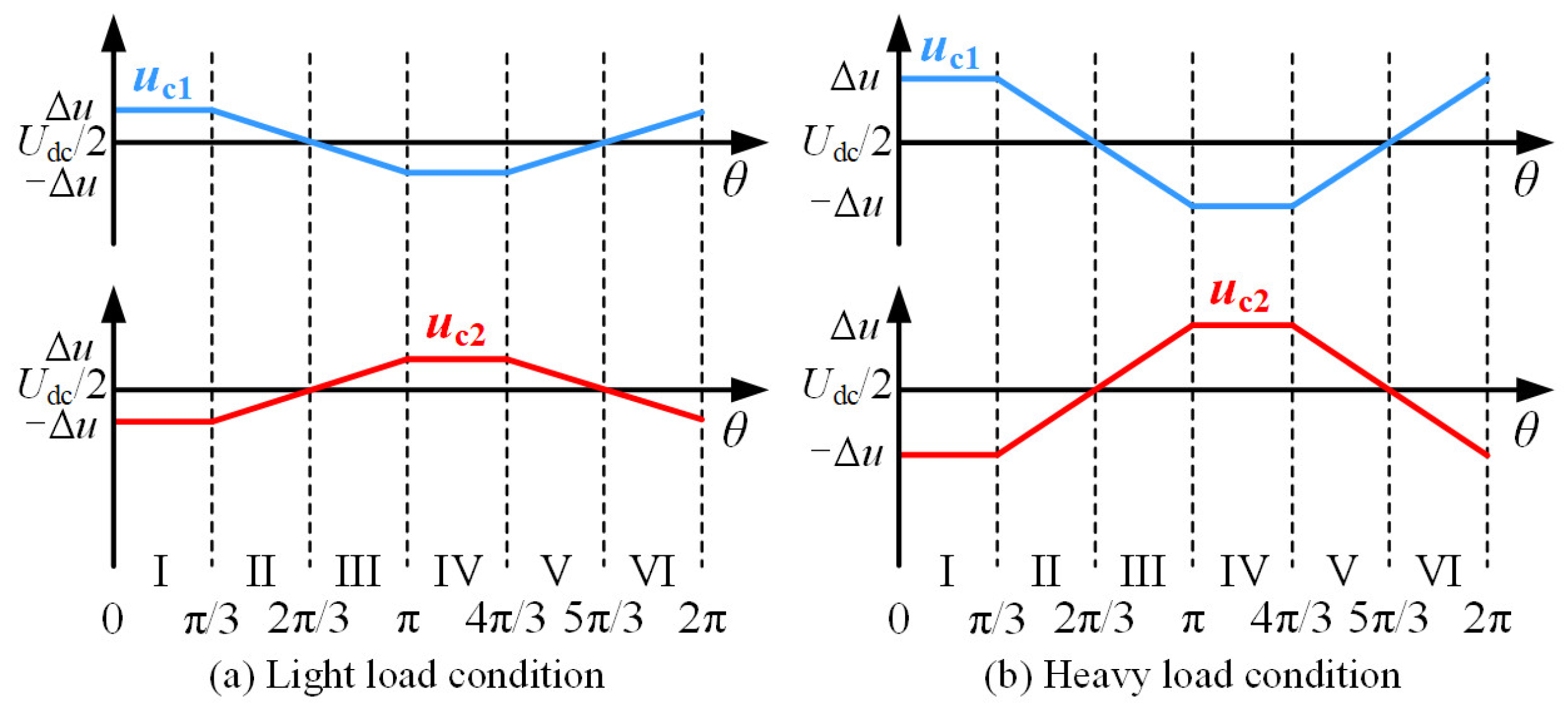
Figure 4 shows the capacitor voltage offset under different load conditions. According to Figure 1 and Figure 2, under sectors I and IV, the phase c current ic tends to zero. At this time, the DC power supply supplies power to the motor. From (8), Δu ≈ 0 can be obtained, and the voltages of the two capacitors remain unchanged. In sectors II and III, phase a and phase c windings and phase b and phase c windings are, respectively, energized. At this time, capacitor C1 supplies power to the motor, uc1 continues to drop, and uc2 continues to rise. Similarly, in sectors V and VI, the capacitor C2 supplies power to the motor, uc2 continuously decreases, and uc1 continuously increases. Because the capacitances of the two capacitors are limited and the initial voltage is Udc/2, the voltages of uc1 and uc2 will be unbalanced and fluctuate up and down in Udc/2 in an electrical cycle.
At present, for the analysis of BLDCM driven by FSTP inverter, the vast majority of strategies ignore the voltage imbalance between the two capacitors. No matter under any working condition (light load or heavy load), the phase c terminal voltage and voltage across capacitor C2 are directly equivalent to the initial voltage Udc/2 for calculation, which introduces calculation deviation and further reduces the control performance of the system.
Considering the fluctuation of capacitor voltage, assuming that the capacitance values of capacitors C1 and C2 are equal (i.e., C1 = C2 = C) when the inverter operates normally, differences in the charging and discharging processes of C1 and C2 result in an imbalance between uc1 and uc2. According to (8), the actual terminal voltages of capacitors C1 and C2 are as follows:
u c 1 = U dc 2 + 1 2 C 0 t i c d t u c 2 = U dc 2 1 2 C 0 t i c d t
From (8) and (9), it can be seen that the capacitor unbalanced voltage Δu is inversely proportional to the capacitance. In practice, the DC capacitance C cannot be infinite, so the voltage fluctuation of the two capacitors is inevitable. Combined with Figure 4b, especially when the motor is under heavy load conditions, the offset Δu becomes larger, which exacerbates this imbalance phenomenon. In the proposed position sensorless control strategy, the accuracy of three-phase terminal voltage calculation will directly affect the accuracy of commutation position detection. Therefore, the unbalanced voltage of the capacitor must be compensated.

4.2. Construction and Principle Analysis of G(θ) Function

According to the law of electromagnetic induction, the back-EMF is numerically equal to the derivative of the permanent magnet flux linkage of the closed loop of the winding with respect to time, and its expression is as follows:
e x = d φ x d t
where φx is the permanent magnet flux linkage of each phase winding, x ∈ {a, b, c}.
Substituting (10) into (1), the terminal voltage of the motor can be obtained as follows:
u a = R s i a + L s d i a d t + d φ a d t + u N u b = R s i b + L s d i b d t + d φ b d t + u N u c = R s i c + L s d i c d t + d φ c d t + u N
From (11), the third term on the right side of the equation represents the back-EMF, which is a function related to the rotor position. Since it is difficult to obtain the neutral point voltage uN of the motor directly, any two expressions in (11) can be subtracted, and the line voltage expression is derived as follows:
u a u b = R s i ab + L s d i ab d t + d φ ab d t u b u c = R s i bc + L s d i bc d t + d φ bc d t u c u a = R s i ca + L s d i ca d t + d φ ca d t
where φab, φbc, and φca are the difference in permanent magnet flux linkage between two-phase windings of the motor. iab, ibc, and ica refer to the differences between the currents of two-phase windings of the motor.
The permanent magnet flux linkage of each phase winding is related to the back-EMF coefficient and the flux linkage waveform function, and the relationship between the three is as follows:
φ a ( θ ) = k e f a ( θ ) φ b ( θ ) = k e f b ( θ ) φ c ( θ ) = k e f c ( θ )
where fa(θ), fb(θ), and fc(θ) are the waveform functions of the flux linkage varying with the rotor position.
By modifying the differential of the flux waveform function with respect to time in the last term of (12) to the product of the differential of the waveform function with respect to position and the differential of position with respect to time, and substituting (13) into (12), the line voltage of BLDCM can be obtained as follows:
u ab = R s i ab + L s d i ab d t + k e ω d f ab ( θ ) d θ u bc = R s i bc + L s d i bc d t + k e ω d f bc ( θ ) d θ u ca = R s i ca + L s d i ca d t + k e ω d f ca ( θ ) d θ
where uab, ubc, and uca are line voltages, ω = dθ/dt is the electrical angular velocity, and fab(θ), fbc(θ) and fca(θ) are the differences in the waveform functions of the flux linkage.
To facilitate analysis, a new position function is defined as follows:
H ab ( θ ) = d f ab ( θ ) d θ
Hab(θ) is a function that can be used for position estimation. According to (14), Hab(θ) function can be further expressed as follows:
H ab ( θ ) = 1 k e ω [ u ab R s i ab L s d i ab d t ]
Similarly, the expressions of the other two H(θ) functions Hbc(θ) and Hca(θ) are as follows:
H bc ( θ ) = 1 k e ω [ u bc R s i bc L s d i bc d t ]
H ca ( θ ) = 1 k e ω [ u ca R s i ca L s d i ca d t ]
Hab(θ), Hbc(θ), and Hca(θ) can be used to estimate the rotor position. However, because the speed ω is included in the above function, it is difficult to obtain the accurate speed in real time in the position sensorless control. In order to eliminate the influence of speed on rotor position estimation in this function, a function independent of speed is obtained by dividing every two H(θ) functions, such as the following:
G ab / ca ( θ ) = [ u ab R s i ab L s d i ab d t ] [ u ca R s i ca L s d i ca d t ]
Similarly, the other two G(θ) functions Gbc/ab(θ) and Gca/bc(θ) are as follows:
G bc / ab ( θ ) = [ u bc R s i bc L s d i bc d t ] [ u ab R s i ab L s d i ab d t ]
G ca / bc ( θ ) = [ u ca R s i ca L s d i ca d t ] [ u bc R s i bc L s d i bc d t ]
According to the expression of the G(θ) function, the value of the G(θ) function can be calculated by measuring voltage, current, and other parameters. Because this function does not contain speed variables and the whole calculation is also independent of the speed, it is also called the speed independent position function method, which makes this method suitable for rotor position estimation in a wider speed range.

4.3. Position Sensorless Control Strategy Based on Voltage Offset Compensation

In most position sensorless control algorithms, low-pass filtering is usually required, and some software filtering is also used to filter out the high-frequency harmonics in the signal, resulting in the phase delay of the detection signal and the commutation error of the motor.
Due to the particularity of the FSTP inverter structure, the terminal voltage uc of the capacitor-connected phase is usually set to a fixed value under ideal conditions, thus eliminating the use of a voltage sensor. At the same time, as shown in Figure 1, if the upper bridge arm switch S1 of phase a is turned on, this phase terminal voltage is the DC bus voltage Udc, and when the lower bridge arm switch S4 of phase b is turned on, this phase terminal voltage is 0. Therefore, when the capacitor voltage is not compensated, the difference between the terminal voltages at each phase can be expressed as follows:
u ab = u a u b u bc = u b u c = u b U dc 2 u ca = u c u a = U dc 2 u a
where ua and ub can be calculated based on the switching state of the FSTP inverter and the DC bus voltage, uc = Udc/2.
It is worth noting that according to the mathematical relationship between the capacitor voltage and current, the terminal voltages of the two capacitors are modeled, respectively, and the unbalanced voltage Δu is compensated by the real-time calculation in (8) and (9), and the accurate phase c terminal voltage uc = uc2 is obtained; then the three-phase terminal voltage differences after capacitor voltage compensation are as follows:
u ab = u a u b u bc = u b u c = u b ( U dc 2 Δ u ) u ca = u c u a = ( U dc 2 Δ u ) u a
by comparing (22) and (23), it can be seen that the derived voltage compensation compensates for the fluctuation of the capacitor voltage. By substituting (23) into the G(θ) function for calculation, the problem of commutation error caused by capacitor voltage imbalance in the FSTP inverter is solved.
Taking Sector II as an example, the terminal voltages of each phase are calculated. Here, da and db represent the PWM modulation duty cycles of phases a and b. In Sector II, the phase currents satisfy ia = I and ib = 0, and no compensation for ic is required. Thus, the upper bridge arm S1 of phase a needs to act as the dominant conducting arm; at this moment, the terminal voltage of phase a is given by ua = daUdc. For phase b, it participates in chopping at this time and is still mainly modulated by the upper bridge arm S3, so its terminal voltage is ub = dbUdc. The terminal voltages of each phase in Sectors III, V, and VI follow the same principle, as shown in Table 2.
In sectors I and IV, the average value of ic is controlled to converge to zero by inserting compensation vectors. By adopting asynchronous modulation for the switches of phases a and b—specifically, when S1 or S4 is turned on individually, phases a and c or phases c and b form a loop, respectively—the current ic is caused to have a tendency to change in the negative or positive direction. Leveraging this rule, in Sector I, if ic > 0, switch S1 is turned on, leading to a decrease in ic; if ic < 0, switch S4 is turned on, causing ic to increase. Ultimately, this controls the phase c current to tend toward zero. Similarly, a comparable conclusion can be drawn for Sector IV. For the other four sectors, refer to Table 1; in these cases, the switches of the floating-phase bridge arm also participate in modulation, and the switches of the upper and lower bridge arms of the same phase adopt complementary PWM modulation.
Taking Sector I as an example, the terminal voltages of each phase in Sectors I and IV are calculated. Here, dc denotes the duty cycle of the floating phase. In Sector I, since the phase c current is prone to distortion, additional compensation vectors need to be inserted to control ic to tend toward zero. Therefore, the terminal voltages of the conducting phases need to incorporate the effect of dc. When ic > 0, it is necessary to turn on the upper bridge arm S1 of phase a to induce a tendency of negative variation in ic; thus, the terminal voltage of phase a is given by ua = (da + dc)Udc. The terminal voltage of phase b is dominated by the lower bridge arm S4, requiring no additional compensation, so ub = (1 − db)Udc. When ic < 0, the switch S4 needs to be turned on to increase ic, ultimately controlling the phase c current to tend toward zero. Consequently, the total duty cycle of the upper bridge arm of phase b is (1 − dbdc), and at this point, ub = (1 − dbdc)Udc while ua = daUdc. A similar logic applies to Sector IV, as detailed in Table 3. According to Table 2 and Table 3, under any sector, the three-phase terminal voltages can be calculated according to the duty cycle of each phase switch and the DC bus voltage and other parameters.
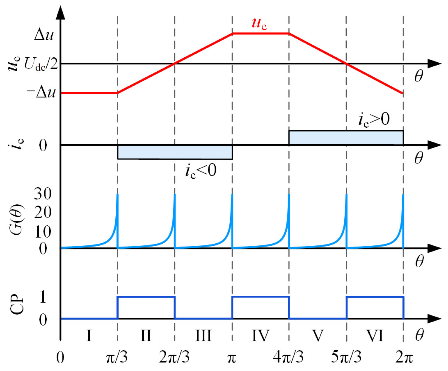
It can be seen from Figure 3 that the jump time of the extreme value of the G(θ) function is the commutation time. Taking Sectors I and IV as examples, the conduction mode of these two sectors is set to ic =0. The back-EMFs ebc and eca undergo zero-crossing in Sectors I and IV, respectively. The function Gca/bc(θ) can accurately reflect the characteristics of ebc and eca. After incorporating capacitor voltage compensation, the transition edges of the selected Gca/bc(θ) function are consistent with the transition edges of the Hall signals, enabling accurate commutation. In Sector II, ib = 0, while in Sector V, ia = 0; the back-EMF eab undergoes zero-crossing in these two sectors. With Hab(θ) as the denominator, the function Gbc/ab(θ) can accurately capture the zero-crossing point of eab to realize commutation. Similarly, the G(θ) function selected for Sectors III and VI is Gab/ca(θ). BLDCM needs to obtain six commutation signals in an electric cycle, and each G(θ) function can provide two commutation signals. Therefore, it is necessary to select different G(θ) functions according to different sectors. The specific G(θ) functions used in each sector are shown in Table 4.
In order to detect the commutation point more accurately, only the upper half of the G(θ) function waveform can be used to determine the commutation signal. By combining the G(θ) function under each sector in Table 4, the G(θ) function waveform shown in Figure 5 can be obtained.
It can be seen from Figure 5 that the compensated phase c terminal voltage uc reflects the voltage fluctuation of capacitor C2 in practice. When it is applied to the G(θ) function, six uniform commutation signals CP can be obtained through the jump edge of this function.
The G(θ) function eliminates the influence of speed by dividing two line back-EMFs and obtains a function independent of speed. Meanwhile, it indirectly uses the zero crossing point of back-EMF to estimate the rotor position, so it does not need the motor to have an ideal trapezoidal wave back-EMF.

4.4. Design of Control System

To sum up, the position sensorless control block diagram of BLDCM driven by FSTP inverter with capacitor voltage compensation is shown in Figure 6.
In Figure 6, it includes two parts: speed and current double closed-loop control and rotor position detection. The output of the motor speed loop is the reference value of three-phase current. The duty cycles da and db of each phase switch are obtained after the current errors of phase a and phase b pass through the PI controller. To solve the problem of three-phase current distortion in sectors I and IV, according to the given value and actual value of phase c current ic, the duty cycle dc is also output through the PI controller. According to the duty cycle calculation method in Table 3, according to the symbol of ic value, add da and db, and finally generate the new modulation duty cycles of phase a and phase b switches. Thus, the phase a and phase b currents track the given value and indirectly control the phase c current ic to zero.
According to Table 2 and Table 3 combined with (23), the three-phase terminal voltages can be calculated by measuring the capacitance C and phase current and combining the duty cycle of the output. It is worth noting that in (8), the actual capacitor voltage value is obtained through real-time calculation so as to compensate for the capacitor unbalanced voltage Δu. Combined with the three-phase current and other information, three G(θ) functions can be obtained. As shown in Table 4, select the appropriate G(θ) function under each sector, and then determine the commutation point by detecting the jump time of this function at the maximum value, and finally realize the commutation control of the motor.
The proposed method not only reduces the commutation deviation caused by capacitor voltage imbalance but also does not need to use a filter in the calculation process, so it is suitable for position sensorless control in a wider speed range. In addition, the proposed method can directly obtain the commutation signal of the motor without delaying the 30° electrical angle, thus avoiding the additional error caused by the delay process.

5. Experimental Results and Analysis

In order to verify the feasibility of the proposed position sensorless control strategy and the correctness of the theoretical analysis, the BLDCM experimental system is built as shown in Figure 7.
In the experimental system, the control unit adopts the hybrid architecture of the TI DSP chip TMS320F28335 from Dallas, USA, and the Altera FPGA chip EP1C6Q240C8. from San Jose, USA. The IRLB4030 produced by IR is selected as MOSFET of the FSTP inverter, phase current is collected using the LA25-NP current sensor from the Swiss company LEM. The experimental system is powered by a Keysight N7973A DC power supply from Keysight Technologies, USA, and the load required by the motor is provided by a set of Magtrol DSP7000 motor test systems produced by Magtrol Corporation in Buffalo, New York, USA. The experimental results are recorded by a YOKOGAWA DLM4058 series eight-channel digital oscilloscope by the Japanese company Yokogawa. Table 5 lists the basic parameters of the BLDCM and FSTP inverter.
In the experiment, the motor control adopts a dual closed-loop structure, where the current loop and speed loop are implemented by PI controllers, respectively. After tuning, the PI gain range for the current loop is generally set as Kp =1~10 and Ki = 100~1000, with a bandwidth of approximately 1~2 kHz. The PI gains for the speed loop are relatively smaller, typically Kp = 0.1~1 and Ki = 10~100, and the bandwidth is controlled within 50~100 Hz to balance dynamic response and system stability. To prevent integrator saturation, an anti-windup method combining integral limiting and back-calculation is introduced in the controller. The sampling frequency is set to 10 kHz, consistent with the PWM frequency, and the ADC module has a 12-bit resolution, which can meet the requirements for accurate sampling of current and voltage signals. A death time of approximately 1.5 μs is set in the power drive section to ensure safe and reliable operation of the devices. Hall current sensors are used for current detection, which can achieve an accuracy of ±1~2% within a range of several tens of amperes. The sampling timing is synchronized with the PWM signals to effectively reduce switching noise interference.

5.1. Balance Verification of Capacitor Voltage

In order to verify the feasibility of DC-side capacitor voltage offset and modeling analysis, Figure 8 shows the experimental results of the motor running at speed n = 1000 r/min and load torque TL = 0.12 N·m. The waveforms from top to bottom are the actual phase c terminal voltage uc, phase c current ic, and the voltage uc2 calculated according to (9) is uc_cal.
It can be seen from Figure 8 that under the above working conditions, the actual phase c terminal voltage uc is offset (unbalanced) and fluctuates up and down at half of the DC bus voltage Udc/2. The offset Δu is about 2.1 V. At positions ① (sector I) and ② (sector IV) in the figure, phase a and phase b are energized, and phase c current ic tends to zero. The DC power supply is used to supply power to the motor winding, and the voltage of uc is approximately unchanged. The change trend of the other four sectors is consistent with the analysis in Figure 4. The calculated voltage uc_cal, according to (9), can better track the actual voltage uc with equal amplitude and consistent phase.

5.2. Analysis of Experimental Results with Uncompensated Capacitor Voltage

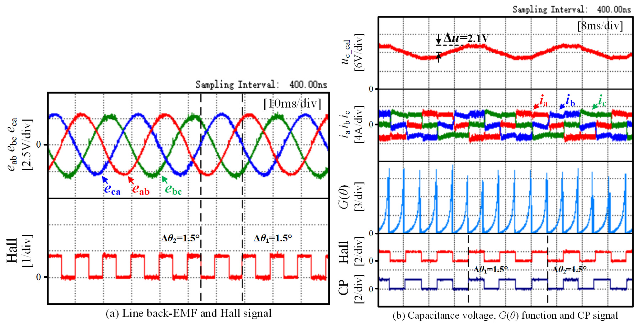
In order to verify the effect of neglecting the capacitor voltage fluctuation on the position sensorless commutation of the motor, Figure 9 shows the experimental results of the motor running at the speed of 1000 r/min and the load torque of 0.12 N·m without capacitor voltage compensation (uc = Udc/2).
The waveforms in Figure 9a from top to bottom are line back-EMF eab, ebc, eca, and Hall signal, respectively. At this time, the calculated line back-EMF is no longer accurate because the capacitor voltage fluctuation is ignored (uc = Udc/2 = 12 V). The angle of the zero crossing point of the line back- EMF eca lagging behind the rising edge of the Hall signal is Δθ1 ≈ 19.6°, and the angle lagging behind the falling edge of the Hall signal is Δθ2 ≈ 18.8°. In addition, the amplitudes of the three line back-EMFs are quite different, so there is a phase deviation between the zero crossing point and the jump edge of the Hall signal.
In Figure 9b, the waveforms from top to bottom are terminal voltage uc, three-phase current, G(θ) function, Hall, and the calculated commutation signal CP. At this time, the signal of the G(θ) function is no longer uniform, and there are wide and narrow alternating waveforms. The commutation signal CP obtained by using the forward jump edge of G(θ) is no longer uniform, and there is a large commutation deviation compared with the accurate Hall signal. The experimental results are consistent with the theoretical analysis, so the unbalanced voltage Δu cannot be ignored.

5.3. Analysis of Experimental Results After Capacitor Voltage Compensation

In order to verify the feasibility and effectiveness of the proposed capacitor voltage compensation method and to compare with the experimental results in Figure 9, Figure 10 shows the experimental results after capacitor voltage compensation when the motor operates at a speed of 1000 r/min and a load torque of 0.12 N·m.
The waveform definition in Figure 10a is consistent with Figure 9a. It can be seen from the figure that the zero crossing points of the line back-EMF eab, ebc, and eca calculated by the proposed method accurately correspond to a jump edge of the Hall signal, respectively, so as to meet the prerequisite for accurate commutation of the motor without a position sensor.
The waveforms in Figure 10b from top to bottom are the calculated capacitor voltage uc_cal, three-phase current, G(θ) function, Hall, and the commutation signal CP after capacitor voltage compensation. Compared with Figure 9, it can be seen that after the introduction of capacitor voltage compensation, considering the unbalanced voltage Δu, the calculated phase c terminal voltage uc_cal can truly reflect the actual terminal voltage uc, making the calculation result of the G(θ) function more accurate and the final calculated G(θ) function waveform more uniform. Under this condition, the commutation signal CP obtained from the forward jump edge of this function can basically accurately correspond to the jump edge of the Hall signal. In addition, it can be seen that when using the CP signal for position sensorless operation, by modulating the three-phase current, the current distortions under sectors I and IV are effectively suppressed, and the square wave control of the current is realized.

5.4. Steady State Experiments Under Different Working Conditions

Because the G(θ) function of BLDCM is a variable independent of speed, the proposed method is not affected by speed in theory and can be applied to a wide speed range. However, it should be noted that due to the particularity of the FSTP inverter topology, phase c is energized in sectors II, III, V, and VI; the DC capacitor C1 or C2 supplies power to the motor winding; and the line voltage between the two phases is approximately half of the DC bus voltage. Therefore, compared with the traditional SSTP inverter, its DC bus voltage utilization rate is only 50%. Thus, the speed operation range and output torque range of the motor are further reduced. All the following tests are also carried out under the rated working condition of the motor.
In order to verify the feasibility of the proposed method for motor operation at different speeds under the condition of low voltage utilization, Figure 11a,b show the experimental waveforms of the position sensorless control method when the motor operates under the load torque of 0.24 N·m and the speed of 750 r/min and 1250 r/min, respectively. The waveform definition is consistent with Figure 10b.
In Figure 11a, when the motor operates under low speed and heavy load conditions, due to the long commutation period and the large amplitude of three-phase current, the voltage across the capacitor fluctuates greatly, and the unbalanced voltage Δu is approximately 5.6 V. In the proposed method, uc_cal can accurately calculate the voltage offset Δu and compensate the capacitor voltage according to the collected phase c current ic. In the position sensorless experimental results, the G(θ) obtained by real-time calculation of the three-phase terminal voltage remains uniform and symmetrical, and the generated commutation CP basically corresponds to the jump edge of the Hall signal, which verifies that the proposed method can operate in the low-speed region.
Figure 11b shows the experimental results of the motor running at 1250 r/min. With the increase in speed, compared with Figure 11a, the commutation period becomes shorter. Under the same load, the unbalance of capacitor voltage decreases, and the voltage offset Δu is approximately 3.8 V. Under the condition of constant control frequency, although the phase current of the motor has a certain distortion, the current control method in this paper can still effectively control the three-phase current as square wave. The experimental results show that the G(θ) function calculated by the proposed method is an ideal symmetrical waveform, and its forward jump edge can accurately correspond to the Hall jump edge, so the estimated commutation signal CP can realize the stable operation without a position sensor.
The amplitude of phase c current is different under different load torques, which leads to different capacitor voltage fluctuations and affects the capacitor voltage compensation effect of the proposed method. In order to verify the performance of the proposed method under different load torques at higher speeds, the experimental waveforms of the proposed method are given in Figure 12a,b when the motor operates at load torques of 0.06 N·m and 0.24 N·m, respectively. The waveform definition in the figure is the same as that in Figure 10b.
The motor in Figure 12a operates under light load conditions, the amplitude of three-phase current is very small, and the unbalanced voltage Δu < 0.1Udc. Combined with the proposed voltage compensation method, the position sensorless control method can also achieve a better control effect under light load conditions, and the calculated commutation signal CP can correspond to the Hall signal one to one.
Figure 12b shows the experimental results of the motor running at a speed of 1400 r/min and a load torque of 0.24 N·m (full load). It can be seen that at the higher speed, the commutation period of the motor is shortened, and the current control is more difficult due to the control frequency of the controller. Meanwhile, because the capacitance of capacitors C1 and C2 is relatively small (both 2500 μF), the voltage across the capacitor is low, resulting in the limited amount of charge stored in the two capacitors, which is difficult to maintain long-term and high-current charging and discharging. During the conduction of c+b− in the figure, the current amplitudes of phase c and phase b are lower than those of other adjacent commutation sections due to the continuous decline of the voltage of capacitor C2. Similarly, during b+c− conduction, with the increase in the calculated voltage uc_cal, the voltage across capacitor C1 is bound to decrease and be lower than Udc/2, which will also reduce the output current. The experimental phenomenon is consistent with the theoretical analysis.
Under the above full load condition, after the capacitor unbalanced voltage compensation Δu is calculated by using (8), the calculated G(θ) function can still maintain an approximately equidistant hyperbolic shape according to the three-phase terminal voltages shown in Table 2 and Table 3, and the maximum points of this function are regularly spaced π/3 electrical angles. The commutation signal CP generated by the proposed method still has a good correspondence with the jump edge of the Hall signal.

5.5. Dynamic Experiment Under Different Working Conditions

In order to verify the feasibility of the proposed method in case of sudden change in load torque, Figure 13 shows the experimental results of a sudden increase in load torque from 0.06 N·m to 0.12 N·m when the motor speed is 1300 r/min. The experimental waveforms in the figure, from top to bottom, are phase c current ic, Hall, and commutation signal CP after capacitor voltage compensation. It can be seen from the experimental results that when the load torque increases suddenly, the proposed method can still estimate the position sensorless commutation signal CP basically corresponding to the phase of the Hall signal after a short transition, so the proposed method has certain anti-load disturbance ability.
In order to verify the feasibility of the proposed method when the speed changes, Figure 14a and Figure 14b, respectively, show the overall waveform diagram and local enlarged diagram of the motor speed increase process.
The waveforms in Figure 14, from top to bottom, are the speed n, Hall signal, and capacitor voltage compensated commutation signal CP, respectively. The load torque is maintained at 0.06 N·m during acceleration, and the motor speed is gradually increased from 750 r/min to 1500 r/min. The experimental results show that the proposed method is still applicable under the increasing speed. Therefore, the rotor position estimation and commutation control of BLDCM driven by FSTP inverter can still be realized by using the proposed method even in the acceleration process.

5.6. Quantitative Performance Analysis

To further demonstrate the superiority of the method proposed in this paper, a comparison is conducted with the method applied in [22] via Table 6. For the method in [22], the commutation error reaches 24° electrical angle under low-speed and heavy-load operating conditions, 14° electrical angle under high-speed and heavy-load conditions, and can only be reduced to 4° electrical angle under low-speed and no-load conditions. In contrast, the proposed method achieves a commutation error of 1.5° under low-speed and no-load conditions, 2.8° under low-speed and heavy-load conditions, 2.7° under high-speed and no-load conditions, and 2.9° under high-speed and heavy-load conditions. Notably, the commutation error of the proposed method is less than 3° electrical angle across all operating conditions.

6. Conclusions and Prospects

Considering the unbalanced characteristics of capacitor voltage, a new position sensorless control method of a motor driven by an FSTP inverter with capacitor voltage compensation is designed in this paper. This method constructs a G(θ) function independent of motor speed and compensates for the influence of capacitor voltage fluctuation on this function according to the derived voltage compensation. On this basis, according to the relationship between the extreme value jump edge of this function after voltage compensation and the commutation point, the accurate commutation signal required for the motor is determined. The proposed method has the following advantages:
(1)
A method to directly calculate the three-phase terminal voltage by using the duty cycle and DC bus voltage is proposed. Because the G(θ) function method does not need to use a filter, it avoids the introduction of phase delay. Meanwhile, the proposed method compensates for the influence of capacitor voltage fluctuation on the position sensorless control algorithm and improves the accuracy of commutation.
(2)
The proposed method is suitable for rotor position estimation in a wider speed range. Meanwhile, it indirectly uses the zero crossing point of back-EMF to estimate the rotor position, so it does not need the motor to have an ideal back-EMF waveform.
(3)
The proposed method does not need to delay the detection signal by 30° electrical angle, avoiding additional error caused by the change in speed in the delay process.
Experimental validation of the current research has been completed on a 70 W motor. Future research will be further advanced in the following directions:
(1)
Extend the proposed control method to kilowatt-class motors, with a focus on verifying its performance and stability under high-power and long-term operation scenarios.
(2)
Integrate an adaptive parameter estimation method to alleviate the impact of mismatches between stator resistance and inductance values on control performance.
(3)
Develop advanced modulation strategies to further improve the DC bus voltage utilization rate or system dynamic response performance under the inherent constraints of the FSTP topology.

Author Contributions

Conceptualization, H.W. and X.L.; methodology, Q.M. and L.Z.; software, L.Z. and C.L.; validation, Y.X., L.Z. and C.L.; formal analysis, Q.M.; investigation, H.W.; resources, C.L.; data curation, L.Z.; writing—original draft preparation, L.Z.; writing—review and editing, H.W., Q.M. and C.L.; project administration, X.L. All authors have read and agreed to the published version of the manuscript.

Funding

This research was funded by the Science Fund of the State Key Laboratory of Engine and Powertrain System of China under Grant skleps-sq-2023-161 and the Joint Fund Key Project of the National Natural Science Foundation of China under Grant U23A20643.

Data Availability Statement

The original contributions presented in the study are included in the article, further inquiries can be directed to the corresponding author.

Conflicts of Interest

Hanrui Wang, Qinghui Meng, and Ying Xin are employees of Weichai Power Co., Ltd. The remaining authors declare that the research was conducted in the absence of any commercial or financial relationships that could be construed as a potential conflict of interest.

Abbreviations

The following abbreviations are used in this manuscript:
BLDCMBrushless DC Motor
FSTPFour-witch Three-phase
SSTPSix-switch Three-phase
CPCommutation Point

References

  1. Chen, S.; Liu, G.; Zhu, L. Sensorless startup strategy for a 315-kW high-speed brushless DC motor with small inductance and nonideal back EMF. IEEE Trans. Ind. Electron. 2019, 66, 1703–1714. [Google Scholar] [CrossRef]
  2. Zhang, H.; Li, H. Fast commutation error compensation method of sensorless control for MSCMG BLDC motor with nonideal back EMF. IEEE Trans. Power Electron. 2021, 36, 8044–8054. [Google Scholar] [CrossRef]
  3. Zhao, D.; Wang, X.; Tan, B.; Xu, L.; Yuan, C.; Huangfu, Y. Fast commutation error compensation for BLDC motors based on virtual neutral voltage. IEEE Trans. Power Electron. 2021, 36, 1259–1263. [Google Scholar] [CrossRef]
  4. Park, J.S.; Lee, K.D.; Lee, S.G.; Kim, W.H. Unbalanced ZCP compensation method for position sensorless BLDC motor. IEEE Trans. Power Electron. 2019, 34, 3020–3024. [Google Scholar] [CrossRef]
  5. Jin, H.; Liu, G.; Zheng, S.Q. Commutation error closed-loop correction method for sensorless BLDC motor using hardware-based floating phase back-EMF integration. IEEE Trans. Ind. Inform. 2022, 18, 3978–3986. [Google Scholar] [CrossRef]
  6. Gambetta, D.; Ahfock, A. New sensorless commutation technique for brushless DC motors. IET Electr. Power Appl. 2009, 3, 40–49. [Google Scholar] [CrossRef]
  7. Wu, X.; Zhu, Z.Q.; Wu, Z. A novel rotor initial position detection method utilizing DC-Link voltage sensor. IEEE Trans. Ind. Appl. 2020, 56, 6486–6495. [Google Scholar] [CrossRef]
  8. Li, P.; Sun, W.; Shen, J.X. Flux observer model for sensorless control of PM BLDC motor with a damper cage. IEEE Trans. Ind. Appl. 2019, 55, 1272–1279. [Google Scholar] [CrossRef]
  9. Chen, S.; Liu, G.; Zhu, L. Sensorless control strategy of a 315 kW high-speed BLDC motor based on a speed-independent flux linkage function. IEEE Trans. Ind. Electron. 2017, 64, 8607–8617. [Google Scholar] [CrossRef]
  10. Zhang, H.F.; Liu, G.; Zhou, X.X.; Zheng, S.Q. High-precision sensorless optimal commutation deviation correction strategy of BLDC motor with asymmetric back EMF. IEEE Trans. Ind. Inform. 2021, 17, 5250–5259. [Google Scholar] [CrossRef]
  11. Huang, C.L.; Wu, C.J.; Yang, S.C. Full-region sensorless BLDC drive for permanent magnet motor using pulse amplitude modulation with DC current sensing. IEEE Trans. Ind. Electron 2021, 68, 11234–11244. [Google Scholar] [CrossRef]
  12. Liu, G.; Chen, X.; Zhou, X.X.; Zheng, S.Q. Sensorless commutation deviation correction of brushless DC motor with three-phase asymmetric back-EMF. IEEE Trans. Ind. Electron. 2020, 67, 6158–6167. [Google Scholar] [CrossRef]
  13. Zeng, Z.; Zheng, W.; Zhao, R.; Zhu, C.; Yuan, Q. Modeling, modulation, and control of the three-phase four-switch PWM rectifier under balanced voltage. IEEE Trans. Power Electron. 2016, 31, 4892–4905. [Google Scholar] [CrossRef]
  14. Haghi, R.; Beiranvand, R.; Shahbazi, M. A quasi-Z-source four-switch three-phase inverter with null vector capability. IEEE Trans. Ind. Electron. 2023, 70, 5421–5432. [Google Scholar] [CrossRef]
  15. Sun, D.; Su, J.; Sun, C.; Nian, H. A simplified MPFC with capacitor voltage offset suppression for the four-switch three-phase inverter-fed PMSM drive. IEEE Trans. Ind. Electron. 2019, 66, 7633–7642. [Google Scholar] [CrossRef]
  16. Pan, L.; Sun, H.; Wang, B.; Su, G.; Wang, X.; Peng, G. Torque ripple suppression method for BLDCM drive based on four-switch three-phase inverter. J. Power Electron. 2015, 15, 974–986. [Google Scholar] [CrossRef]
  17. Xia, C.L.; Wu, D.; Shi, T.N.; Chen, W. A current control scheme of brushless DC motors driven by four-switch three-phase inverters. IEEE J. Emerg. Sel. Top. Power Electron. 2017, 5, 547–558. [Google Scholar] [CrossRef]
  18. Zhou, D.; Li, X.; Tang, Y. Multiple-vector model predictive power control of three-phase four-switch rectifiers with capacitor voltage balancing. IEEE Trans. Power Electron. 2018, 33, 5824–5835. [Google Scholar] [CrossRef]
  19. Zhu, C.; Zeng, Z.Y.; Zhao, R.X. Comprehensive analysis and reduction of torque ripples in three-phase four-switch inverter-fed PMSM drives using space vector pulse-width modulation. IEEE Trans. Power Electron. 2017, 32, 5411–5424. [Google Scholar] [CrossRef]
  20. BLee, K.; Kim, T.H.; Ehsani, M. On the feasibility of four-switch three-phase BLDC motor drives for low cost commercial applications: Topology and control. IEEE Trans. Power Electron. 2003, 18, 164–172. [Google Scholar]
  21. Lin, C.; Hung, C.; Liu, C. Position sensorless control for four-switch three-phase brushless DC motor drives. IEEE Trans. Power Electron. 2008, 23, 438–444. [Google Scholar] [CrossRef]
  22. Niasar, A.H.; Vahedi, A.; Moghbelli, H. A novel position sensorless control of a four-switch, brushless DC motor drive without phase shifter. IEEE Trans. Power Electron. 2008, 23, 3079–3087. [Google Scholar] [CrossRef]
  23. Qu, J.; Li, K. Model predictive direct torque control of a three-phase four-switch inverter induction motor driving system. In Proceedings of the 12th IET International Conference on Advances in Power System Control, Operation and Management (APSCOM 2022), Hybrid Conference, Hong Kong, China, 7–9 November 2022; pp. 77–82. [Google Scholar]
  24. Chen, W.; Zhu, L.; Wang, S.; Li, X.; Shi, T.; Xia, C. Rotating Restart Method for TPFS Inverter-Fed Sensorless PMSM Drive System Based on Dual Effective Voltage Vectors Injection. IEEE Trans. Power Electron. 2024, 39, 11708–11722. [Google Scholar] [CrossRef]
Figure 2. Ideal line back-EMF, phase back-EMF, and phase current of BLDCM.
Wevj 16 00582 g002
Figure 3. Relationship between G(θ) function and Hall signal.
Wevj 16 00582 g003
Figure 4. Capacitor voltage offset under different working conditions.
Wevj 16 00582 g004
Figure 5. Relationship between capacitor voltage after voltage compensation, G(θ) function and commutation signal.
Wevj 16 00582 g005
Figure 6. Position sensorless control block of BLDCM driven by FSTP inverter with capacitor voltage compensation.
Wevj 16 00582 g006
Figure 7. Experimental system of brushless DC motor.
Wevj 16 00582 g007
Figure 8. Capacitance voltage uc, ic, and calculated voltage uc_cal at 1000 r/min and 0.12 N·m.
Wevj 16 00582 g008
Figure 9. Experimental waveforms of uncompensated capacitor voltage (uc = Udc/2) at 1000 r/min and 0.12 N·m.
Wevj 16 00582 g009
Figure 10. Experimental waveforms after capacitor voltage compensation at 1000 r/min and 0.12 N·m.
Wevj 16 00582 g010
Figure 11. Experimental waveforms at different speeds.
Wevj 16 00582 g011
Figure 12. Experimental waveforms under different load torques.
Wevj 16 00582 g012
Figure 13. Experimental waveform of sudden increase in torque.
Wevj 16 00582 g013
Figure 14. Experimental waveforms of motor speed increase.
Wevj 16 00582 g014
Table 1. Current reference value under each sector.
SectorIIIIIIIVVVI
iaII0II0
ibI0II0I
ic0II0II
Table 2. Terminal voltage of each phase under sectors II, III, V, and VI.
Sectoruaubuc
IIdaUdcdbUdcUdc/2 − Δu
IIIdaUdcdbUdc
V(1 − da)UdcdbUdc
VIdaUdc(1 − db)Udc
Table 3. Terminal voltage of each phase under sectors I and IV.
Sectoricuaubuc
Iic ˃ 0(da + dc)Udc(1 − db)Udc
(1 − dbdc)Udc
(db + dc)Udc
dbUdc
Udc/2 − Δu
ic ˂ 0daUdc
IVic ˃ 0(1 − da)Udc
ic ˂ 0(1 − dadc)Udc
Table 4. G(θ) function for each sector.
SectorI and IVII and VIII and VI
G(θ)Gca/bc(θ)Gbc/ab(θ)Gab/ca(θ)
Table 5. The parameters of BLDCM and FSTP inverter.
ParametersValueUnit
Rated power PN70W
Rated voltage UN24V
Rated current IN4A
Rated torque TN0.24N·m
Rated speed nN3000r/min
Phase resistance Rs0.316Ω
Phase inductance Ls0.628mH
Poles pairs p2
Capacitance C1 = C22500μF
PWM carrier frequency20kHz
Table 6. Quantitative performance analysis.
Operating Conditions Δ θ of Proposed Method Δ θ of Other Methods [22]
Low speed with no load1.5°
Low speed with heavy load2.8°24°
High speed with no load2.7°4.5°
High speed with heavy load2.9°14°
Disclaimer/Publisher’s Note: The statements, opinions and data contained in all publications are solely those of the individual author(s) and contributor(s) and not of MDPI and/or the editor(s). MDPI and/or the editor(s) disclaim responsibility for any injury to people or property resulting from any ideas, methods, instructions or products referred to in the content.