1. Introduction
Owing to their low cost, simple structure, wide speed range, and other advantages, switched reluctance motors (SRMs) have been extensively employed in mining machinery, electric vehicles, robotic control applications, and aviation [
1,
2]. However, owing to its distinctive double-salient structure, switched reluctance motors exhibit several drawbacks, including pronounced nonlinearity and substantial torque ripple. In addition, conventional regulation scarcely achieves precise control of the motor, and researchers have long been devoted to enhancing the performance of switched reluctance motors through novel control and design methodologies [
3,
4].
Reference [
5] proposed a DSRM control system based on a flexible neural network. This control system demonstrated stable operation of the DSRM, coupled with excellent dynamic performance and robust anti-interference capability. Reference [
6] presented a phase torque estimation method based on magnetic co-energy and Fourier series expansion. Subsequently, it introduced novel sector division rules and fundamental voltage vector selection for torque prediction, demonstrating superior performance in suppressing torque pulsation, velocity dynamic response, and system robustness. Reference [
7] described a two-step method. In the first step, a comprehensive curve analysis of the reference current was conducted using an optimization technique specifically designed to minimize torque ripple. In the second step, the optimized current curve was applied to the SRM via an adaptive hysteresis band controller, thereby effectively mitigating radial vibration. Reference [
8] proposed a regenerative braking control strategy that integrates a braking force optimization controller and an angle optimization controller, thereby enhancing the real-time performance and effectiveness of the braking torque control approach. Reference [
9] presented an alternative approach for a grid-connected high-speed SRM drive system, which enhances the power factor, substantially reduces control complexity, and ensures a rapid dynamic response. Reference [
10] proposed a novel quasi-sine wave excitation scheme for SRMs, aimed at minimizing torque ripple. Reference [
11] introduced a hybrid control strategy that combines a torque sharing function (TSF) with sliding mode control (SMC), enabling reduced torque ripple and enhanced dynamic response speed. Reference [
12] presented an enhanced model predictive torque control strategy for an SRM driver, incorporating candidate voltage vector optimization. This approach effectively mitigates torque ripple while improving system efficiency. Reference [
13] introduced an enhanced direct instantaneous torque controller for SRMs, which significantly improved the torque distribution and operational efficiency of the machine. Reference [
14] presented a novel optimization control method by utilizing diverse torque sharing functions (TSFs) and optimization algorithms, thereby enhancing the robustness of the system. Reference [
15] introduced a predictive control method for accurately tracking current references in SRM drivers. This method utilized a simplified piecewise linear flux linkage model, thereby eliminating the need for extensive lookup tables and reducing the requirement to only a few model parameters. Consequently, it achieved efficient memory utilization and superior performance.
In recent years, SRMs have gained increasing attention in electric vehicle (EV) applications owing to their simple structure, low manufacturing cost, wide speed range, and inherent fault tolerance. These advantages position SRMs as a promising alternative to conventional permanent magnet synchronous motors (PMSMs) and induction motors (IMs), which currently dominate EV drive systems. Nevertheless, their widespread adoption remains limited by the inherent problem of high torque ripple, which gives rise to undesirable vibration and acoustic noise. Developing advanced control strategies to mitigate torque ripple is therefore essential for enhancing driving comfort, operational efficiency, and the overall competitiveness of SRM-based propulsion systems in EVs. In this regard, the improved SMC strategy proposed in this study is particularly relevant, as it provides a practical pathway for enabling SRMs to be more effectively integrated into existing EV drive solutions. Furthermore, the proposed control scheme is inherently compatible with current EV drive architectures. Because the enhancement is achieved primarily through algorithmic improvements rather than hardware redesign, it can be seamlessly implemented on conventional motor control platforms. This compatibility facilitates the deployment of SRMs in present EV systems, where they may serve either as an alternative or as a complementary solution to PMSM- and IM-based drives [
16].
Therefore, an improved SMC strategy for direct torque control of SRMs is proposed in this study [
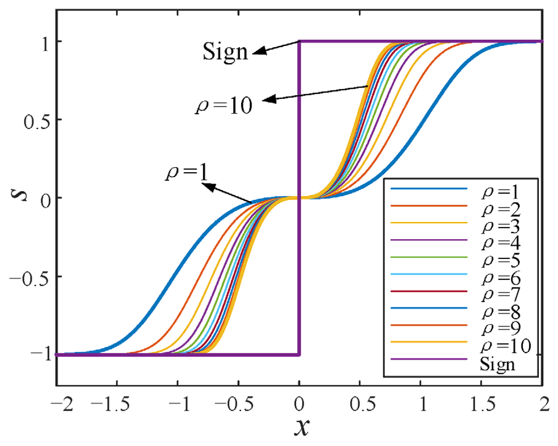
17]. This strategy creatively reconstructs the mathematical model of the control law to address torque pulsation and dynamic response lag issues in the application of the traditional exponential control law SMC for SRMs, namely: (1) replacing the discontinuous sign function with a continuous and smooth sigmoid function to fundamentally suppress control chattering; and (2) introducing a new state variable to more accurately characterize the dynamic behavior of the motor. To further enhance the robustness and adaptability of the system, this study applies the SSA [
18] to the global intelligent optimization of key control parameters. In this scheme, torque ripple is substantially reduced, dynamic adjustment time is considerably shortened, and the overall system performance is stably enhanced under various complex operating conditions.
4. Sparrow Search Algorithm
Given the nonlinear characteristics and strong electromagnetic coupling of traditional parameter adjustment methods, optimal control is scarcely achieved. To address this issue, this study employs the SSA for multi-objective parameter optimization.
The SSA is a swarm intelligence optimization algorithm inspired by the foraging behavior and antipredation strategies of sparrows. In this algorithm, sparrows are categorized into discoverers and followers. Discoverers are responsible for locating food sources and guiding the movement of the entire population, while followers rely on the discoverers to obtain food. Compared with particle swarm optimization, which easily falls into local optima, and genetic algorithms (GA), which suffer from slow convergence, SSA demonstrates remarkable advantages in motor control and other strongly coupled parameter optimization problems through its three-dimensional division of labor: global exploration by discoverers, local exploitation by followers, and random escape by the vigilant. Its adaptive Levy flight strategy effectively overcomes the tendency of gray wolf optimization to oscillate in parameter-sensitive regions, while the elite guidance mechanism avoids the initial-value dependence of quantum genetic algorithms (QGA). The SSA demonstrates several advantages, including high convergence accuracy, rapid convergence speed, strong optimization capability, and high computational efficiency. Therefore, this study employs the SSA to optimize the parameter tuning of the sliding mode controller.
4.1. The Fundamental Steps of the SSA
- (1)
The population and associated parameters of the algorithm are initialized, followed by the calculation of fitness values for each individual.
- (2)
The position of the discoverer is updated using the following formula:
where
t denotes the number of current iterations.
represents the position of the i-th value sparrow during the
t-th iteration, where
j = 1, 2, …, d. Here, d denotes the number of variables to be optimized,
T is the maximum number of iterations, and
α is a random parameter with a value range of (0, 1].
Q is a random variable following a normal distribution, and
L is a 1 × d matrix with all elements equal to 1.
R2 denotes the warning threshold, while STSTST represents the safety threshold. The value range under consideration is defined by
R2. If
R2 is less than STSTST, the surrounding environment is considered secure, allowing for an expanded search scope. Conversely, if
R2 is greater than or equal to ST, the surrounding environment is considered hazardous, necessitating relocation to another area for foraging.
For the followers, the position update formula is expressed as follows:
Here, Xp represents the optimal position identified by the discoverer, Xworst denotes the global worst position, and A is a 1 × d matrix in which each element is randomly assigned either 1 or −1. Additionally, if the entrant belongs to the better-performing group in the first half, their position is updated using the first subformula. Conversely, if the entrant is part of the underperforming group in the second half, the sparrow, driven by hunger, flies to another location randomly.
For sparrows that are aware of potential danger, their initial positions are randomly generated within the population. The update formula is as follows:
In the formula, denotes the global optimal position, represents the step control parameter and follows a normal distribution of random numbers with a mean of 0 and a variance of 1. K is a random number within the range of [−1, 1], indicates the fitness of the current sparrow, while and correspond to the current global optimal and worst fitness, respectively. represents the smallest constant.
4.2. The Fundam
For the evaluation of torque, torque pulsation is adopted as the fitness function. The mathematical expression defining torque pulsation is presented as follows:
In the formula, , and represent the maximum, minimum, and average torque values of the motor during stable operation, respectively.
At the same time, within the context of the motor control system, response characteristics are considered equally important. Consequently, speed is established as a performance indicator, and the integral of the time-weighted absolute error (ITAE) of speed is utilized as the fitness function.
The expression is presented as follows:
where
t denotes the simulation time.
Therefore, the fitness function of the entire system can be expressed as:
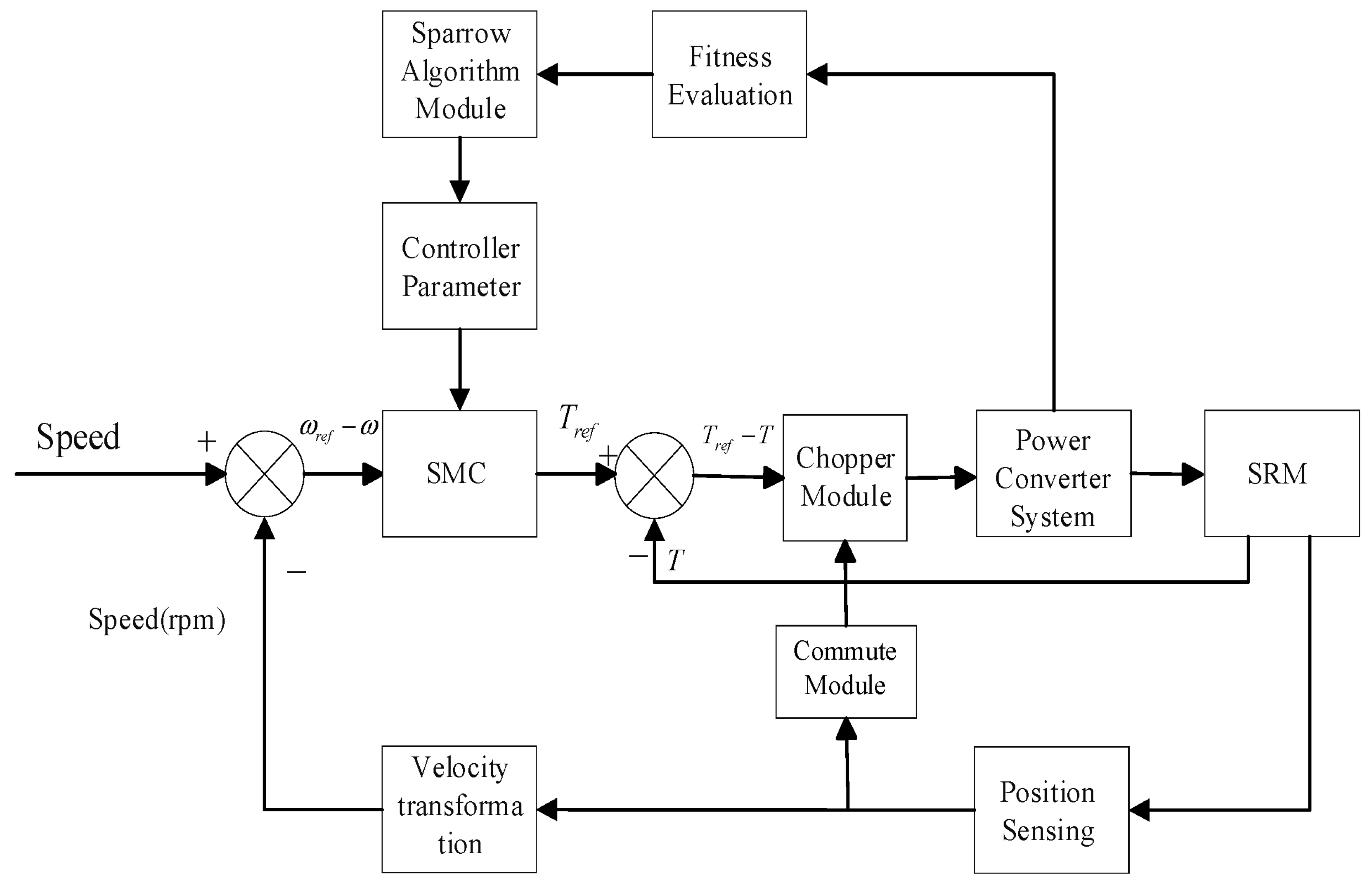
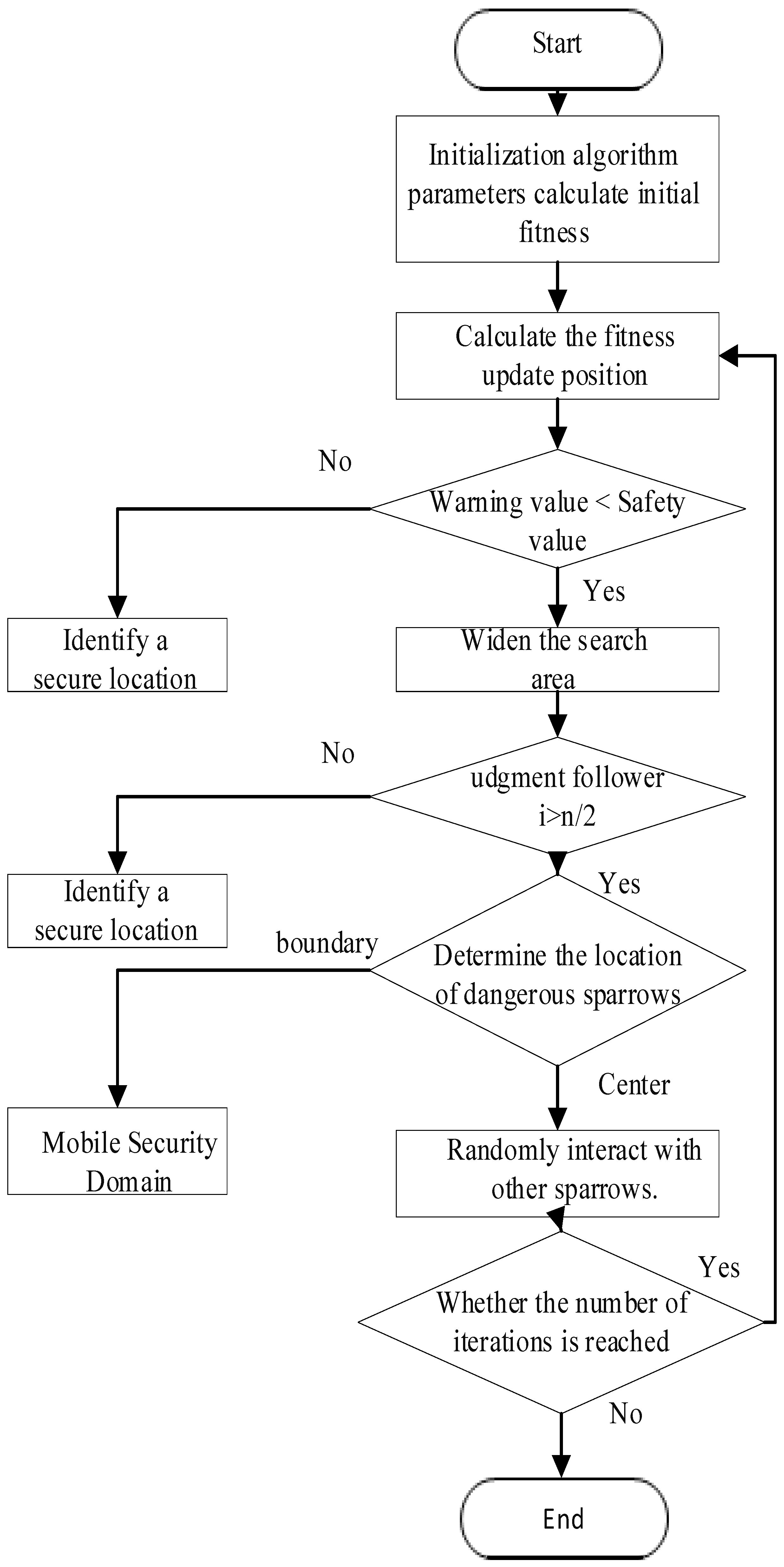
In summary, the fundamental block diagram and flowchart for tuning the sliding mode controller parameters using the SSA are presented in
Figure 4 and
Figure 5.
5. Simulation
Based on the principle illustrated in
Figure 2, an SMC system for the SRM, featuring an improved front-and-rear three-phase 6/4 pole structure, was constructed in MATLAB/Simulink (R2022a). Given that an excessively large value of
k amplifies the effect of |x
1|, while an overly small value of
k diminishes this effect, the range of
k is determined to be (0, 10). Additionally, the value of α must approximate the value of |x
1| as it approaches the sliding mode plane, and ε must vary smoothly during this process. Consequently, the value of α is set within the range (0, 1), and ε is constrained to the interval (0, 10).
The parameter selection of the SSA is strictly guided by the convergence characteristics of the algorithm and the computational constraints imposed by the hardware. The population size is set to 30, a value determined based on a balance between dimensional compatibility criteria and computational efficiency. Preliminary experiments indicate that when the population size is increased from 20 to 30, the rate of improvement in fitness reaches 11.2%, whereas an increase to 50 results in only a 2.3% improvement, consistent with the law of diminishing marginal returns. The maximum number of iterations has been limited to 10, as determined by two contributing factors. First, convergence analysis indicates that 85% of the optimization cases reach a stable state within eight generations. Second, a single simulation is completed in approximately 182 s, and the total duration for the tenth generation is maintained within 30 min, thereby fulfilling the timeliness requirements of engineering optimization.
To achieve optimal control performance, the SSA is employed to optimize the key parameters of both the conventional sliding mode controller and the improved sliding mode controller. The optimal parameter combinations obtained from the optimization process are presented in
Table 1 and
Table 2, respectively. Through SSA-based optimization, it is ensured that both controllers are compared under their respective optimal configurations, so that subsequent performance enhancements can be clearly attributed to improvements in the control law itself, rather than to differences in parameter tuning. The main parameters of the SRM used in the simulation model are shown in
Table 3, providing the necessary basis for validating the control strategies.
The transition time and torque ripple of the SRM during its operation from startup to steady-state speed were analyzed to systematically evaluate the performance of the conventional SMC strategy versus the improved SMC strategy.
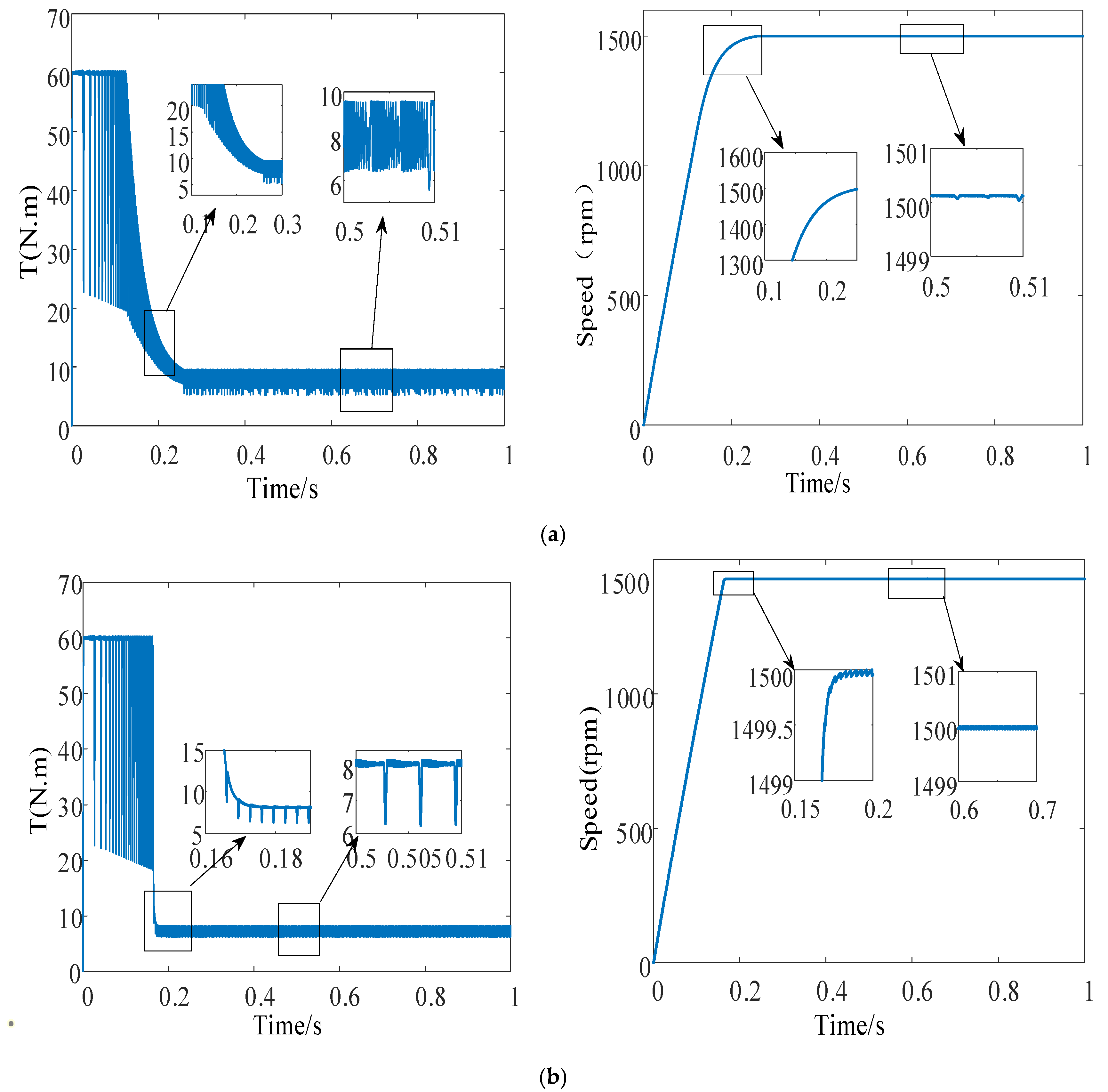
Figure 6 illustrates the speed and torque ripple waveforms of the SRM during the transition from startup to stabilization at 1500 rpm under a load of 8 N·m. As shown in
Figure 6a, the SRM drive system utilizing the conventional SMC strategy requires 0.23 s to reach steady-state at 1500 rpm. By contrast, as depicted in
Figure 6b, the time required with the improved SMC strategy is reduced to 0.17 s, demonstrating that the improved SMC strategy exhibits superior dynamic performance compared with the conventional approach. Furthermore, a comparison of
Figure 6a,b reveals that the minimum and maximum motor torques under the conventional SMC strategy are 6 and 9.8 N·m, respectively. By adopting the improved SMC strategy, the maximum torque is maintained at 6 N·m, while the minimum torque is adjusted to 8 N·m, resulting in a reduction of torque ripple.
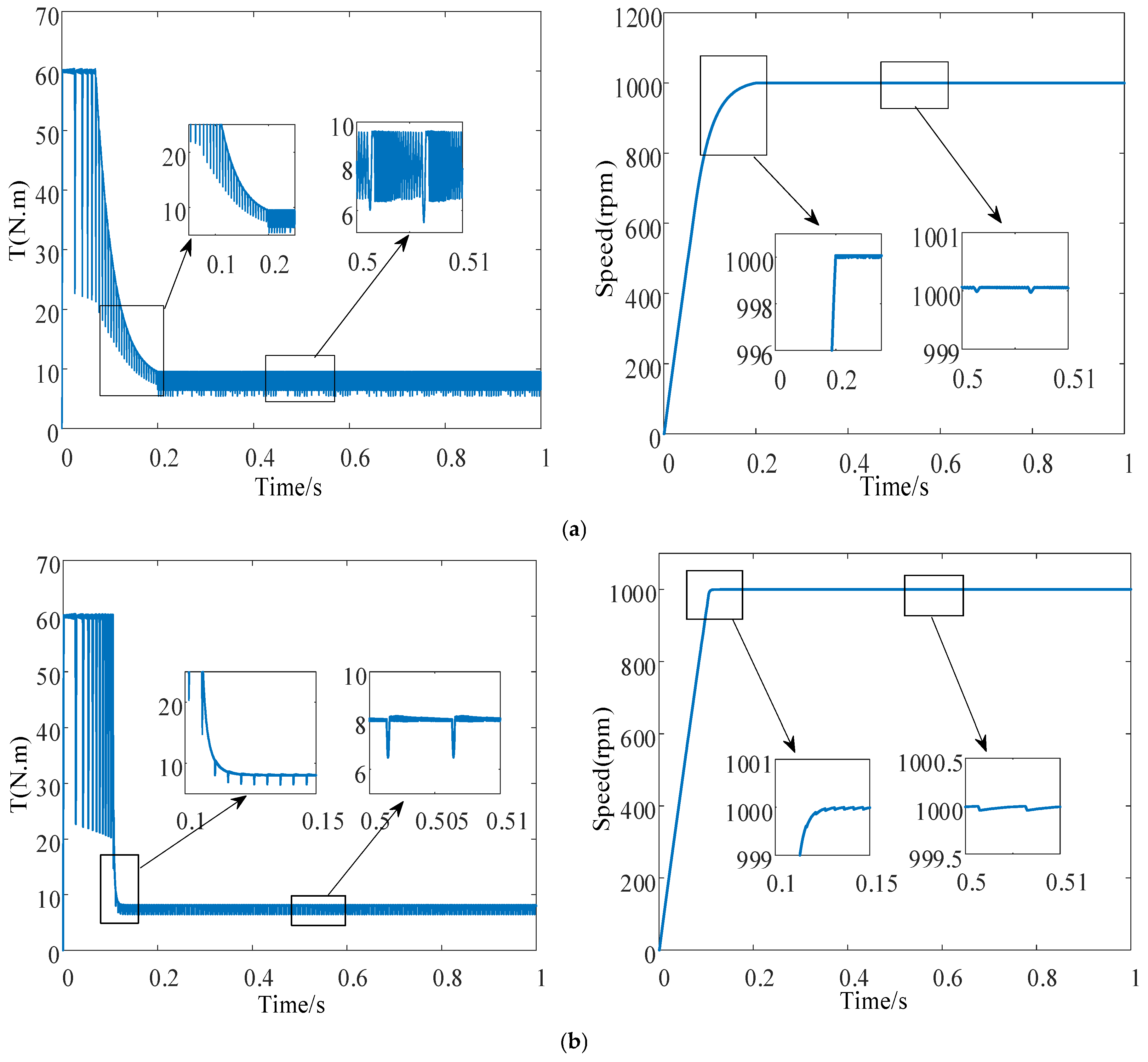
Figure 7 illustrates the speed and torque ripple waveforms of the SRM during the transition from startup to stabilization at 1000 rpm under a load of 8 N·m. A comparison of
Figure 7a,b reveals that, when the conventional SMC method is employed, the motor requires 0.22 s to stabilize at 1000 rpm after startup and 0.19 s to reach 990 rpm, which constitutes 85% of the total startup duration. By contrast, adopting the improved SMC strategy reduces the stabilization time to 0.12 s, while the time required to reach 990 rpm is shortened to 0.09 s, representing 70% of the total startup duration. This result indicates that the improved SMC strategy achieves a faster approach to the target speed during the initial phase; that is, less time is required to reach the sliding mode surface. When the conventional SMC strategy is employed, the minimum and maximum motor torques are 6 and 9.7 N·m, respectively. With the modified SMC strategy, these values are refined to 6.2 and 8 N·m, respectively. Furthermore, under the conventional method, torque values are densely distributed within the range of 6.3–9.7 N·m, whereas with the improved strategy, they are confined to the narrower range of 6.5–8 N·m, resulting in reduced torque ripple. These findings confirm that the improved SMC strategy demonstrates superior dynamic and steady-state performance under variable-speed conditions, thereby validating the effectiveness of the proposed approach.
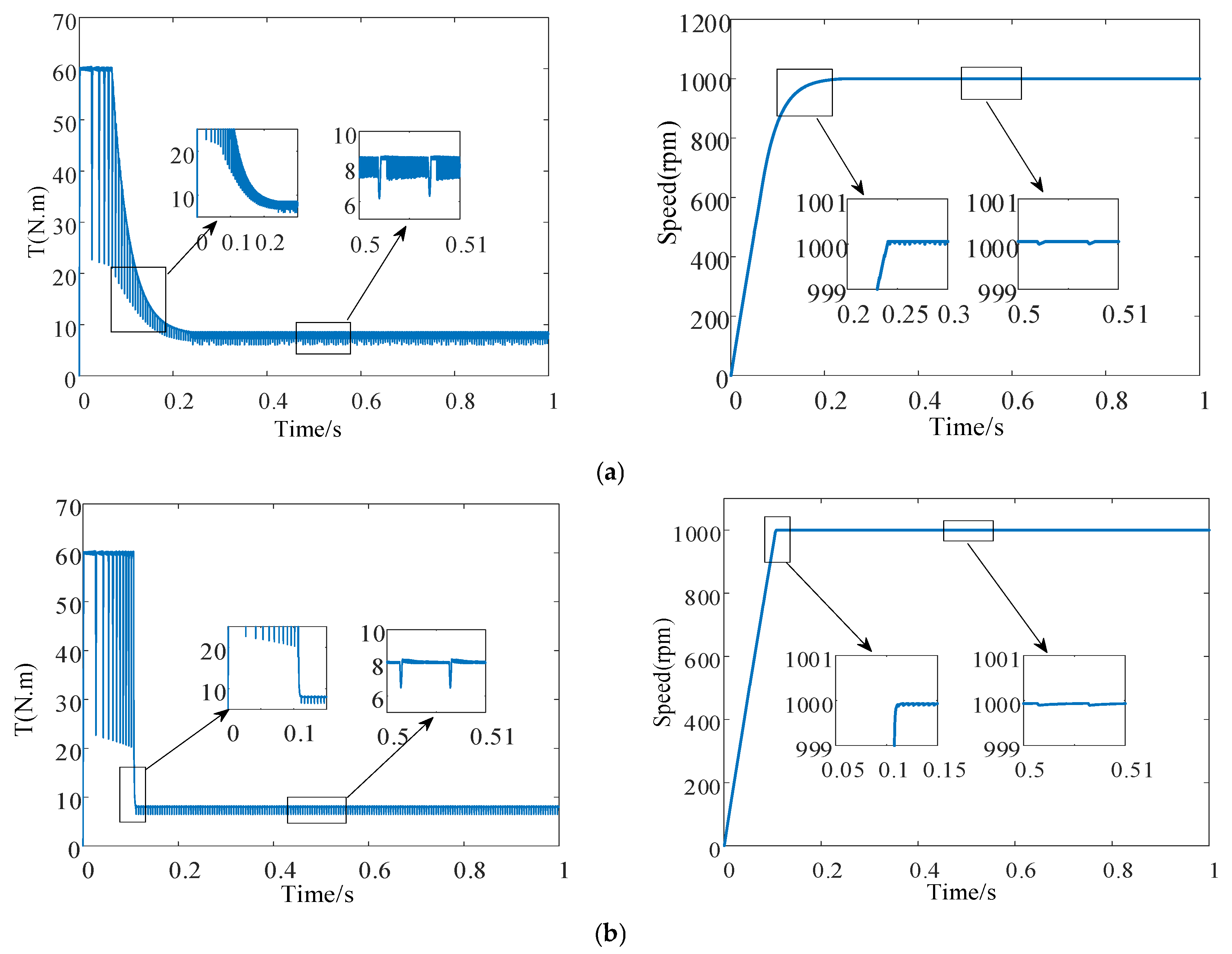
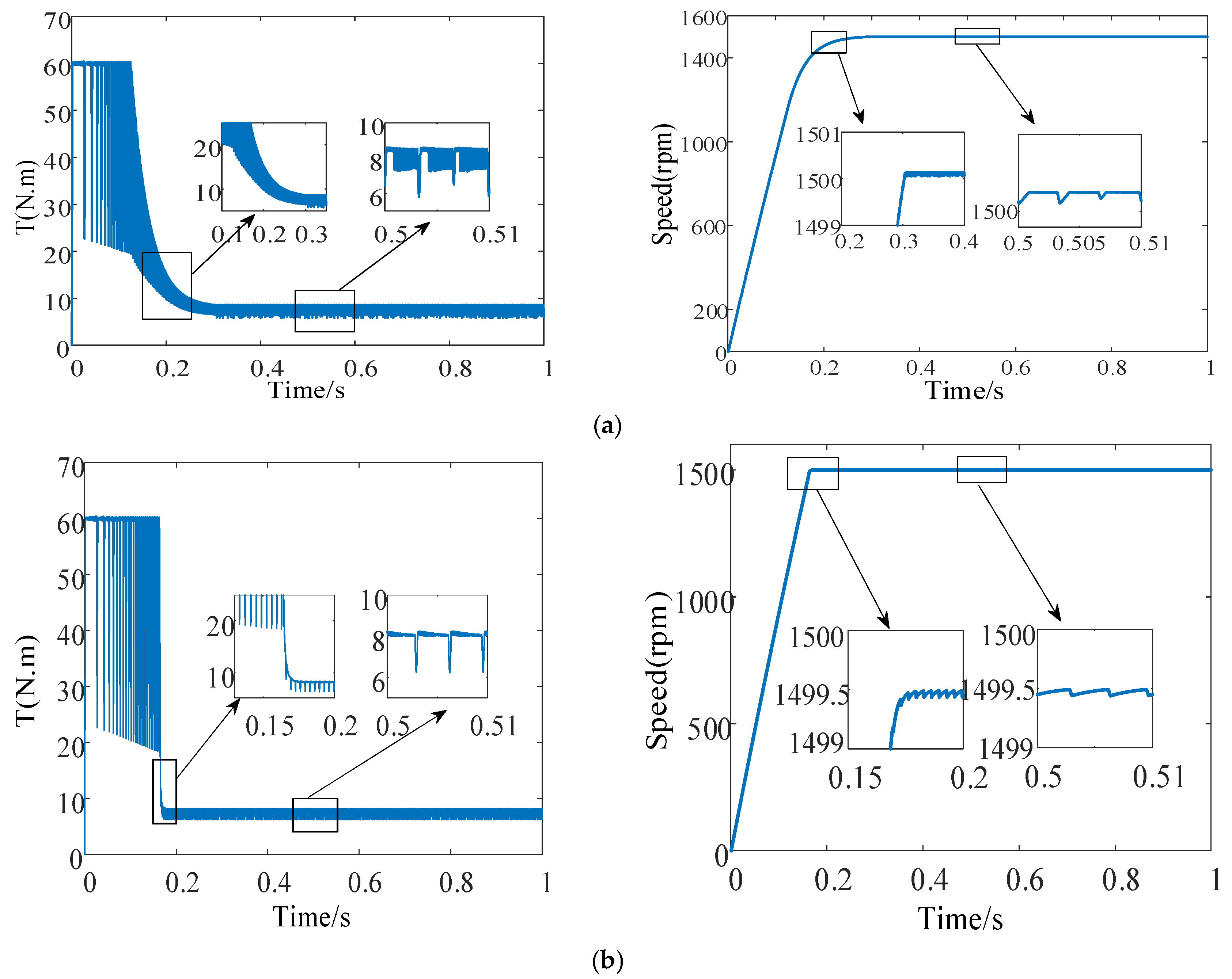
Under a load of 7 N·m,
Figure 8 and
Figure 9 illustrate the speed and torque waveforms of the motor during the startup process under the conventional SMC strategy and the improved SMC strategy. These figures are analyzed under identical loading conditions, but at different motor speeds. The load torque is set to 7 N·m, while the specified motor speeds are 1000 rpm and 1500 rpm, respectively. A comparison of
Figure 8a,b reveals that, when the specified speed is 1000 rpm, the motor startup time using the improved SMC strategy is reduced from 0.27 s, as achieved by the conventional SMC strategy, to 0.1 s, representing a reduction of 0.17 s. This result indicates that the proposed strategy exhibits a faster dynamic response. Similarly, a comparison of
Figure 9a,b reveals that, when the specified speed is 1500 rpm, the motor startup time using the conventional SMC strategy is 0.32 s, whereas that using the improved SMC strategy is shortened to 0.17 s, achieving a reduction of 0.15 s.
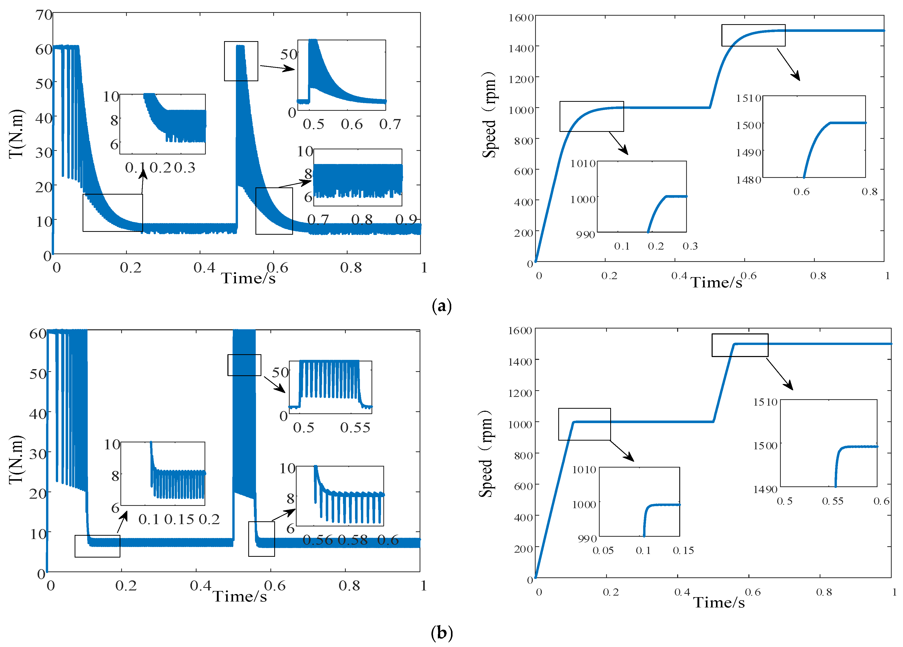
At 0.5 s, a speed perturbation was introduced into the SRM to evaluate the robustness and complexity of the proposed design.
Figure 10 presents the waveforms of speed and torque when a step change in speed from 1000 r/min to 1500 r/min was applied at 0.5 s. As shown in
Figure 10a, under a torque perturbation at 0.5 s, the SRM with the conventional SMC strategy reached a steady state only at 0.67 s, corresponding to a response time of 0.17 s. By contrast, as illustrated in
Figure 10b, under the same condition, the SRM with the improved SMC strategy stabilized at 0.57 s, with a response time of only 0.07 s. These results indicate that, under torque perturbation, the improved SMC strategy exhibits a markedly faster response than the conventional SMC strategy. Moreover, the torque ripple associated with the improved SMC strategy is lower than that observed with the conventional SMC strategy. A further comparison between
Figure 10a and b reveals that, under a speed perturbation at 0.5 s, the transition from the step change in speed to a stable state required 0.2 s with the conventional SMC strategy, whereas only 0.056 s was needed with the improved SMC strategy. This finding demonstrates that, under speed perturbation, the improved SMC strategy achieves a significantly shorter response time compared with the conventional SMC strategy.
To comprehensively evaluate the overall performance of the improved SMC strategy proposed in this study,
Table 4 summarizes the comparative data of key performance indicators. It can be observed from
Table 4 that, compared with the conventional SMC strategy, the improved SMC strategy exhibits a pronounced effect in suppressing torque ripple. Under the 7 N–1000 rpm operating condition, the torque ripple range is reduced from 6.0–9.0 N·m under the conventional SMC strategy to 6.2–8.0 N·m, resulting in an approximate 40% reduction in fluctuation. In terms of dynamic response speed, the improved SMC strategy reduced the response time from 0.15 s to 0.08 s in the worst-case scenario, representing an improvement of 46.7%. As shown in
Table 3, notably, under conditions of a step change in speed, the response time of the improved SMC strategy also demonstrates significant advantages, indicating enhanced anti-disturbance capability and robustness. Collectively, these results demonstrate that the improvement of the SMC strategy effectively enhances steady-state accuracy while maintaining system speed performance.
