

Traction Synchronous Machine with Rotor Field Winding and Two-Phase Harmonic Field Exciter

 ,
,  ,
,  , and
, and 
Abstract
1. Introduction
- (1)
- Large losses and heating in the rotor: induction motors tend to generate significant losses and heat within the rotor, which can affect efficiency and performance;
- (2)
- Increased weight and size: compared to rare-earth permanent magnet synchronous motors (PMSMs) [3], induction motors are generally heavier and bulkier, which can be a drawback in applications where space and weight are critical factors;
- (3)
- Higher power rating of the inverter for wide constant power speed range (CPSR): when a wide CPSR is needed, the power rating of the inverter must be considerably higher. For example, the authors of [4] showed that a traction drive using an IM with a rated power of 50 kW and a CPSR of 3.5 requires an inverter with a rated power of 125 kVA. Another study [5] examining a traction IM with an output mechanical power of 50 kW and a CPSR of 4:1 also found the need for a 125 kVA inverter. This results in an inverter utilization factor of just 0.4 (50/125). If the CPSR is even wider, the utilization factor decreases further, reducing efficiency [1].
- (4)
- Temperature pulsations when parking on a slope: when a vehicle equipped with an induction motor is parked on a slope and the motor is used in electric brake mode at zero rotor speed, significant temperature pulsations occur in the traction converter switches. These fluctuations can shorten the lifespan of the inverter components [1,6]. To mitigate this, the rated power of the inverter must be significantly increased [7]. In contrast, synchronous machines can hold a vehicle on a slope at zero rotor speed using DC current in the stator phases, avoiding these temperature fluctuations. This ability to maintain constant temperature over the electric period without large fluctuations makes synchronous machines more reliable in this context.
- (1)
- High cost of rare-earth permanent magnets (PMs): the cost associated with rare earth PMs remains a significant barrier.
- (2)
- Technological dependence: the reliance on a limited number of suppliers for rare earth elements creates a technological dependency that can affect production and supply chains.
- (3)
- Environmental impact: The extraction process for rare earth materials used in PMs has severe environmental consequences, making it a less sustainable option.
- (4)
- High-speed losses: At high rotational speeds, PMSMs experience large losses due to uncontrolled PM magnetic flux, especially with a wide constant power speed range (CPSR). This results in increased heating and a higher risk of magnet demagnetization.
- −
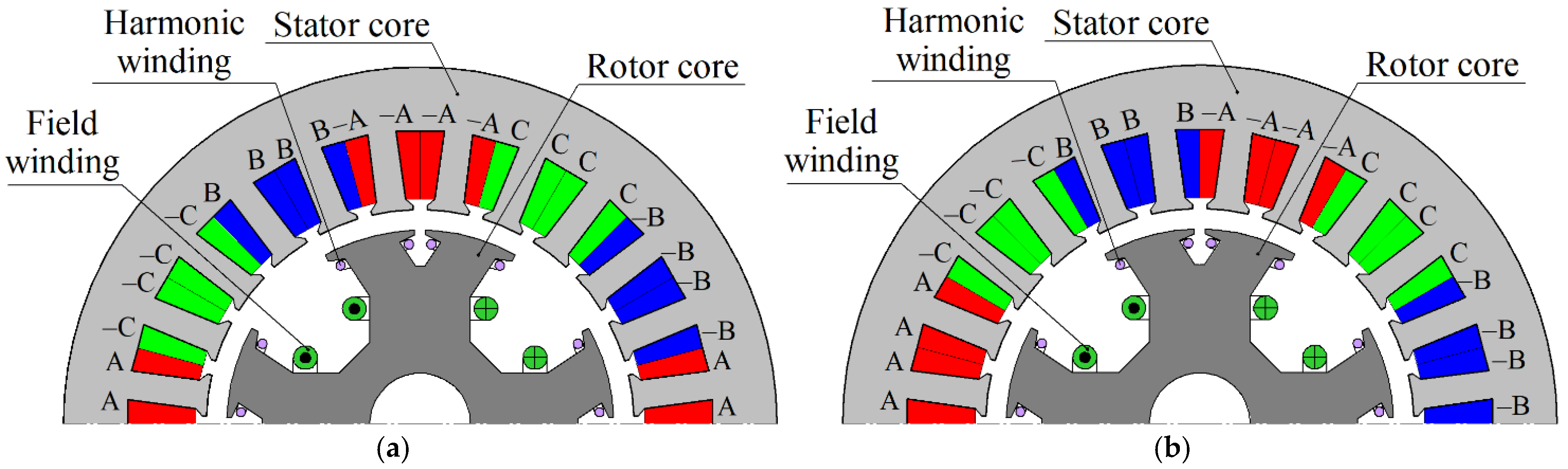
- The transfer of energy to the harmonic exciter winding does not occur effectively at all rotor positions. This reduces the magnitude of the electromotive force (EMF) at the output of the harmonic exciter and makes it impossible to start the motor at certain rotor positions.
- −
- The slot sections of the harmonic winding coils placed in the slots of the field winding make a small contribution to the output EMF, which also reduces the efficiency of the harmonic exciter and complicates its design.
- −
- To effectively transfer energy to harmonic winding, it is necessary that the angular size of the rotor sub-tooth is approximately equal to the pole pitch of the spatial third harmonic, and the entire rotor tooth is approximately equal to the period of the spatial third harmonic, that is, approximately 120 electrical degrees. This limits the possibilities for optimizing the design of a synchronous machine and achieving high efficiency.
- −
- An inverter with a hysteresis current regulator is used to power the armature winding. This requires high-precision current sensors and fast switching transistors.
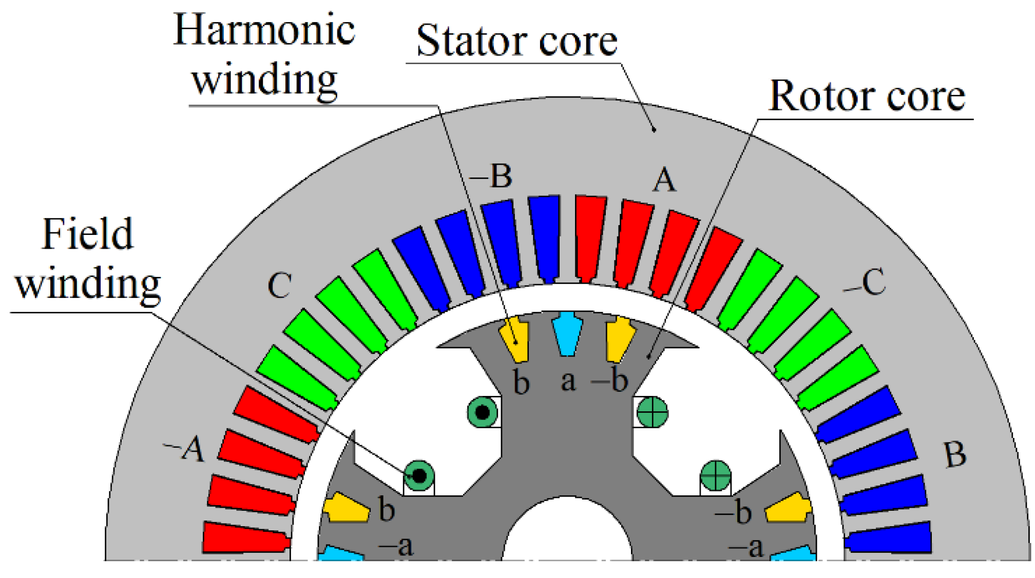
2. Features of the Proposed HESM Design
3. Simplified Model of HESM Control System
4. Features of the Diode Bridge Model
4.1. Determination of Possible States of the Diode Bridge
- (1)
- The “through state” or short circuit state. A current flows through the field winding, supported by self-induction. All currents in the harmonic winding are less than the field current. The diodes are open through at least one column (two diodes connected in series). Therefore, all voltages on the diode bridge are zero; that is, we obtain the required additional four equations:
- (2)
- Working state. In this state, the voltage drop across the diode bridge is not zero. Some phases of the harmonic winding are connected to the field winding and power it. Each diode column i = a, b, c (two diodes connected in series) can be in one of three states, encoded by flags Ki, i = a, b, c.
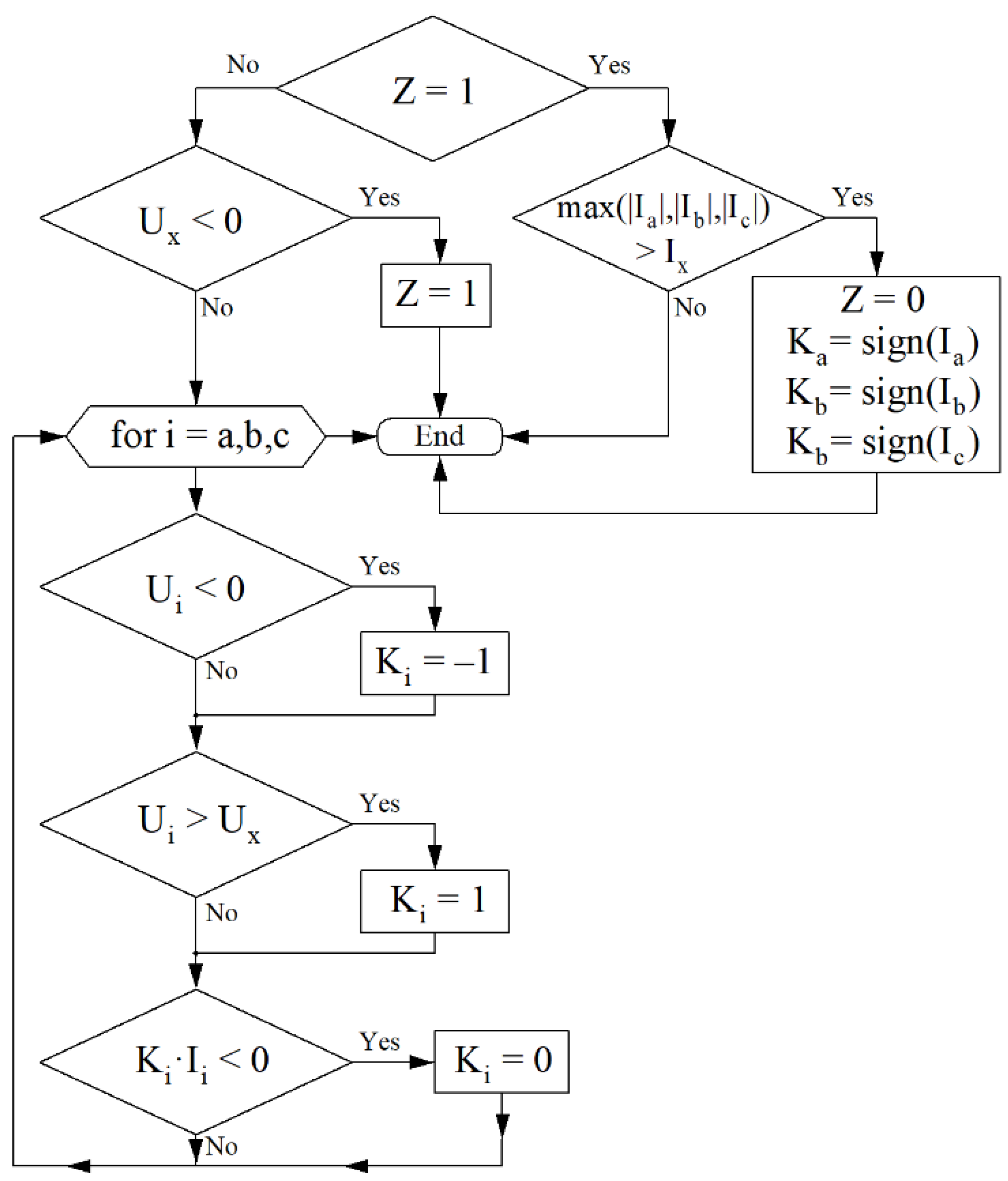
4.2. Description of the Algorithm for Determining the State of the Diode Bridge at the Next Step
- −
- In the short-circuit state (z = 1), the maximum module current max (| Ia |,| Ib |,| Ic |) flowing into the diode bridge is less than the rectified current. If this condition is violated, the short-circuit state is destroyed (z = 0). In this case, Ki takes values ±1 in accordance with the sign of the corresponding current Ii.
- −
- The rectified voltage is always positive. However, if, due to time discretization at some step, this condition is violated Ux < 0, then the operating state of the bridge z = 0 is no longer possible, and the short-circuit state z = 1 is switched on.
- −
- In operating state z = 0, if the current flows through one of the diodes of the i-th column Ki = ±1, then Ki and Ii are always of the same sign. However, if, due to time discretization at some step, this condition is violated Ki ∙ Ii < 0, then current flow through the column is not possible, Ki = 0.
- −
- The voltage on the stray (off) phase Ki = 0 in operating mode z = 0 is between 0 and Ux. However, if, due to time sampling at some step, this condition is violated, then the phase connects: Ki = −1, if Ui < 0; Ki = 1 if Ui > Ux.
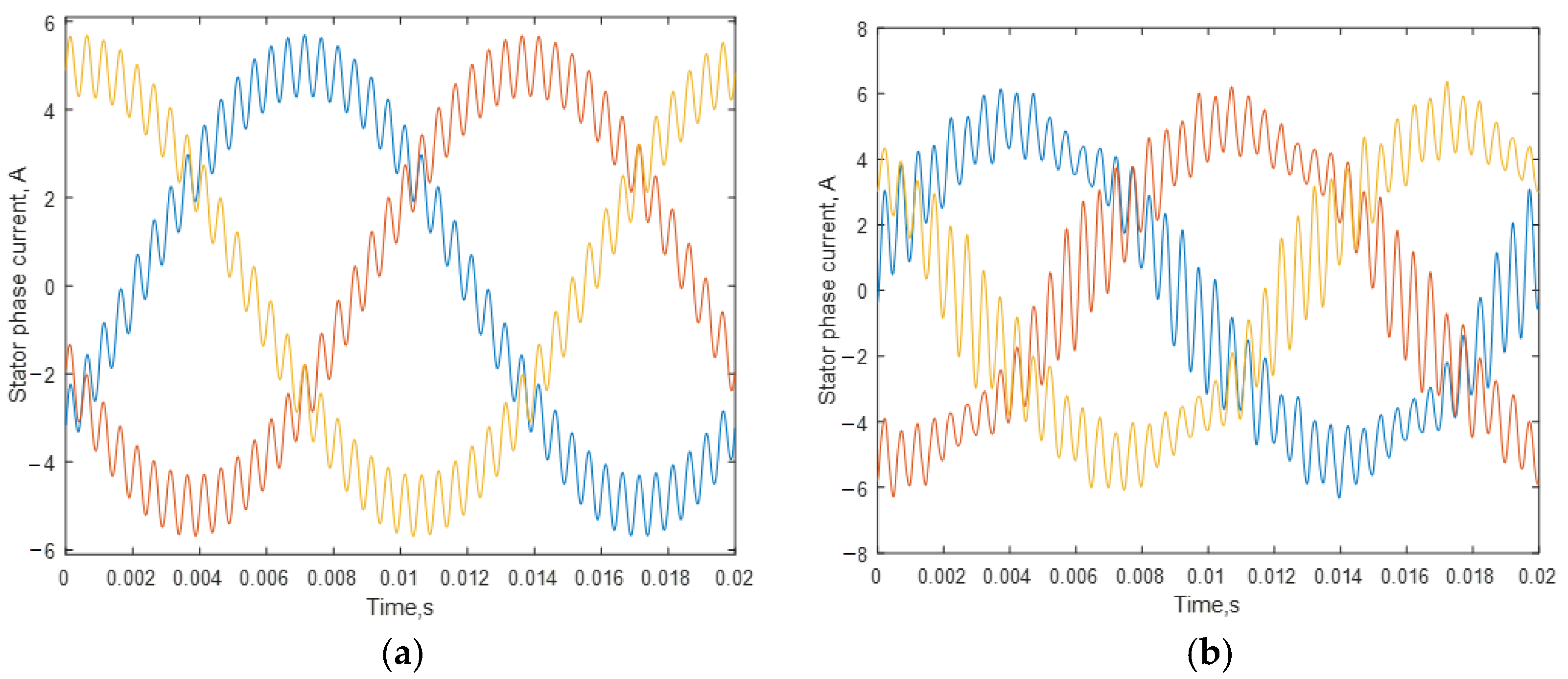
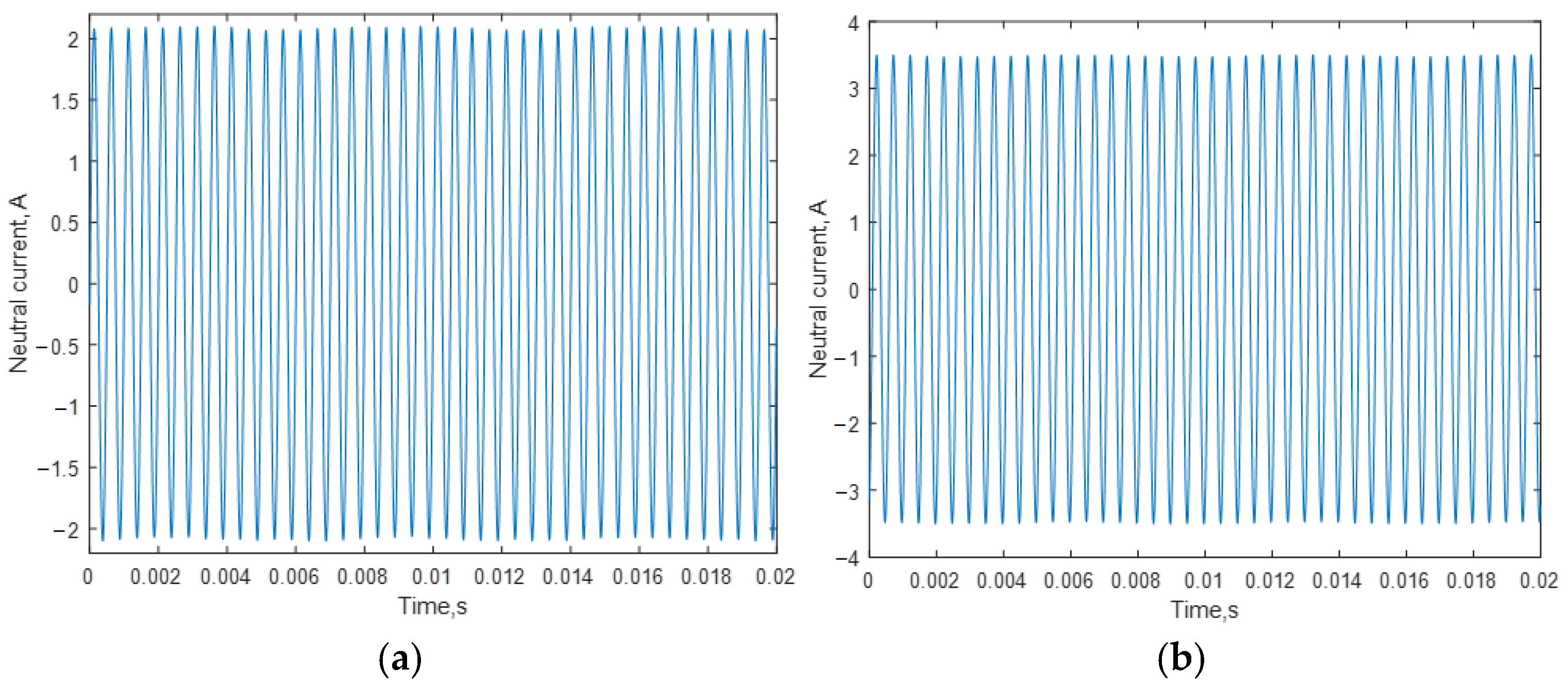
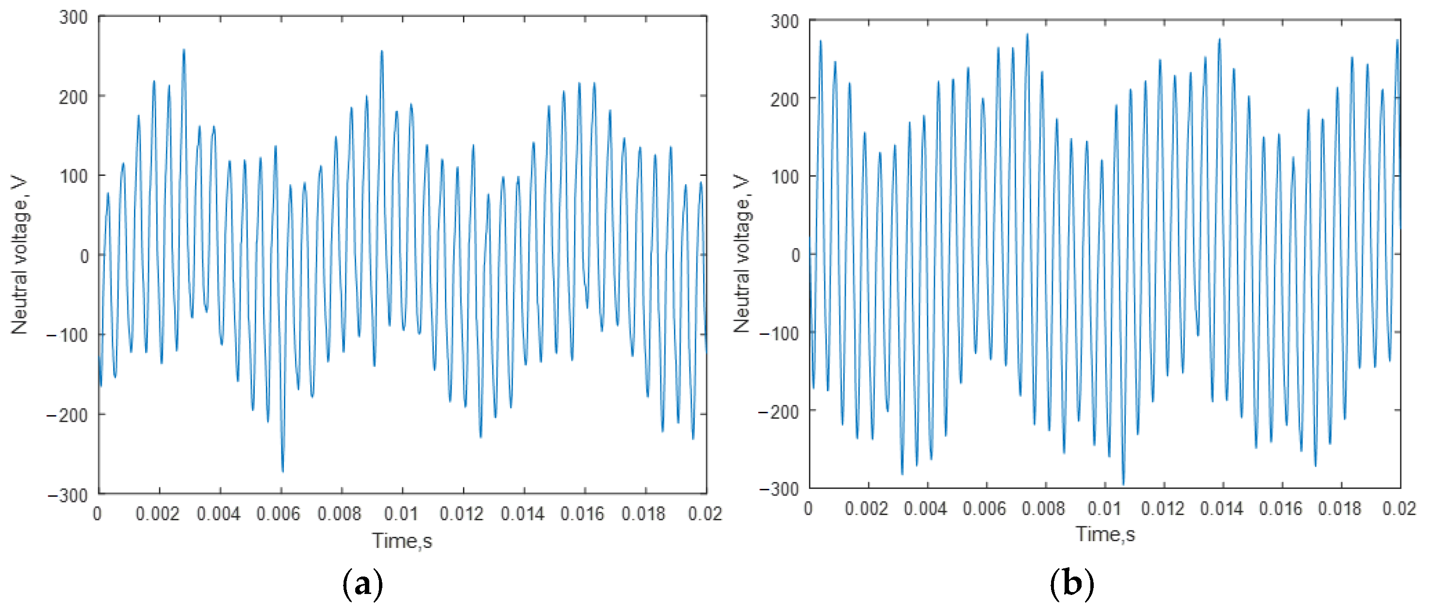
5. Results of Mathematical Modeling
6. Conclusions
Author Contributions
Funding
Data Availability Statement
Conflicts of Interest
Glossary
| List of Abbreviations | |
| CPSR | Constant power speed range |
| EESM | Electrically excited synchronous machine |
| EMF | Electromotive force |
| FOC | Field-oriented control |
| HESM | Harmonic Exciter Synchronous Machine |
| IM | Induction motor |
| PM | Permanent magnet |
| PMSM | Permanent magnet synchronous motor |
| PWM | Pulse-width modulation |
| List of Mathematical Symbols | |
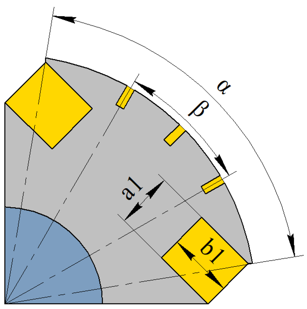
| a1 | Height of the field winding coil, mm |
| b1 | Width of the field winding coil, mm |
| i | Imaginary unit |
| I0 | Neutral wire current, Ф |
| I0ref | Reference of the neutral wire current |
| Ia, Ib, Ic | Phase currents of the rotor rectifier, A |
| IA, IB, IC | Stator phase currents, A |
| IaL, IbL | Phase currents of the harmonic winding, A |
| Idq | Stator currents in the rotating coordinate system, A |
| Idqref | Reference of dq current |
| Irms | Phase armature current RMS, A |
| Ix | Field winding current, A |
| K | Logical flag of the rotary rectifier model state |
| p | Pole pair number |
| PF | Power factor |
| P1 | Input electric real power, W |
| P2 | Output mechanical power, W |
| r | Field winding resistance, Ohm |
| R | Stator phase resistance, Ohm |
| R0inv, | Proportional gain of the PI controller of neutral current, Ohm |
| Rdqinv | Proportional gain of the PI controller of dq current, Ohm |
| t | Time variable, s |
| Ua, Ub, Uc | Phase voltages the rotor rectifier, V |
| Udq | Stator voltages in the rotating coordinate system, A |
| udq | Output of PI-voltage controller |
| Ush | Harmonic winding neutral point voltage, V |
| Ux | Field winding voltage, V |
| Vrms | Line-to-line voltage RMS, V |
| z | Logical flag of the rotary rectifier model state |
| α | Rotor pole angular dimension, mechanical degrees |
| β | Angular distance between the slots of the harmonic winding, mechanical degrees |
| ΔUdq | Correction for PI-voltage controller |
| ε | Voltage drop across one open diode, V |
| η | Efficiency, % |
| Φ0 | Zero-sequence flux linkage, Wb |
| Φa, Φb | Phase flux linkages of harmonic winding, Wb |
| Φdq | Stator flux linkages in the rotating coordinate system, Wb |
| Φx | Field winding flex linkage, Wb |
| Ω | Rotor mechanical angular frequency, radian per second, rad/s |
| ∫0 | Integral gain of the PI controller of neutral current, Ohm |
| ∫dq | Integral gain of the PI controller of dq current, Ohm |
References
- Dmitrievskii, V.; Prakht, V.; Valeev, E.; Paramonov, A.; Kazakbaev, V.; Anuchin, A. Comparative Study of Induction and Wound Rotor Synchronous Motors for the Traction Drive of a Mining Dump Truck Operating in Wide Constant Power Speed Range. IEEE Access 2023, 11, 68395–68409. [Google Scholar] [CrossRef]
- Prakht, V.; Dmitrievskii, V.; Kazakbaev, V.; Valeev, E.; Paramonov, A.; Anuchin, A. Assessmen of the Feasibility of Using a Synchronous Homopolar Motor Instead of an Induction Motor in a Traction Drive with a Wide Constant Power Speed Range. IEEE Open J. Veh. Technol. 2024, 5, 950–966. [Google Scholar] [CrossRef]
- Dianov, A.; Anuchin, A. Offline Measurement of Stator Resistance and Inverter Voltage Drop Using Least Squares. IEEE Access 2023, 11, 17053–17065. [Google Scholar] [CrossRef]
- Kim, B.; Lee, J.; Jeong, Y.; Kang, B.; Kim, K.; Kim, Y. Development of 50 kW traction induction motor for electric vehicle (EV). In Proceedings of the 2012 IEEE Vehicle Power and Propulsion Conference, Seoul, Republic of Korea, 9–12 October 2012; pp. 142–147. [Google Scholar] [CrossRef]
- Zhu, Z.Q.; Chu, W.Q.; Guan, Y. Quantitative comparison of electromagnetic performance of electrical machines for HEVs/EVs. CES Trans. Electr. Mach. Syst. 2017, 1, 37–47. [Google Scholar] [CrossRef]
- Sharp, A.; Monir, S.; Day, R.J.; Vagapov, Y.; Dianov, A. A Test Rig for Thermal Analysis of Heat Sinks for Power Electronic Applications. In Proceedings of the 2023 IEEE East-West Design & Test Symposium (EWDTS), Batumi, Georgia, 22–25 September 2023; pp. 1–4. [Google Scholar] [CrossRef]
- Ali, Y.; Kulik, E.; Anuchin, A.; Do, D.H. Thermal Cycling Effect in a Traction Inverter for Star-connected and Open-end Winding Permanent Magnet Synchronous Motors with Nearly Constant Losses Current Regulation. In Proceedings of the 2022 29th International Workshop on Electric Drives: Advances in Power Electronics for Electric Drives (IWED), Moscow, Russian, 26–29 January 2022; pp. 1–6. [Google Scholar] [CrossRef]
- Doerr, J.; Fröhlich, G.; Stroh, A. The Electric Drivetrain with Three-motor Layout of the Audi E-tron S. MTZ Worldw. 2020, 81, 16–25. [Google Scholar] [CrossRef]
- Popescu, M.; Goss, J.; Staton, D.A.; Hawkins, D.; Chong, Y.C.; Boglietti, A. Electrical Vehicles—Practical Solutions for Power Traction Motor Systems. IEEE Trans. Ind. Appl. 2018, 54, 2751–2762. [Google Scholar] [CrossRef]
- BMW Group. The First-Ever BMW iX3, PressClub Global, Article. Available online: https://www.press.bmwgroup.com/global/article/detail/T0310696EN/the-first-ever-bmw-ix3?language=enhttps://www.netcarshow.com/bmw/2021-ix3/ (accessed on 2 January 2025).
- Renault Fluence, Z.E. Is a Positive Influence. 2012. Available online: https://www.torque.com.sg/reviews/renault-fluence-z-e-is-a-positive-influence/ (accessed on 2 January 2025).
- Noeland, J.; Nuzzo, S.; Tessarolo, A.; Alves, E. Excitation System Technologies for Wound-Field Synchronous Machines: Survey of Solutions and Evolving Trends. IEEE Access 2019, 7, 109699–109718. [Google Scholar] [CrossRef]
- Maier, M.; Parspour, N. Operation of an Electrical Excited Synchronous Machine by Contactless Energy Transfer to the Rotor. IEEE Trans. Ind. Appl. 2018, 54, 3217–3225. [Google Scholar] [CrossRef]
- Illiano, E. Design of a Highly Efficient Brushless Current Excited Synchronous Motor for Automotive Purposes. Ph.D. Thesis, ETH-Zürich, Zurich, Switzerland, 2014. [Google Scholar] [CrossRef]
- Boldea, I.; Andreescu, G.; Rossi, C.; Pilati, A.; Casadei, D. Active Flux Based Motion-Sensorless Vector Control of DC-Excited Synchronous Machines. In Proceedings of the 2009 IEEE Energy Conversion Congress and Exposition, San Jose, CA, USA, 20–24 September 2009; pp. 2496–2503. [Google Scholar] [CrossRef]
- AHLE Develops Highly Efficient Magnet-Free Electric Motor. Press Release. Available online: https://www.mahle.com/en/news-and-press/press-releases/mahle-develops-highly-efficient-magnet-free-electric-motor--82368 (accessed on 2 January 2025).
- Dmitrievskii, V.; Prakht, V.; Kazakbaev, V. Traction Synchronous Machine with Rotor Field Winding and Controlled Magnetic Anisotropy. In Proceedings of the 2024 International Conference on Industrial Engineering, Applications and Manufacturing (ICIEAM), Sochi, Russian, 20–24 May 2024; pp. 512–517. [Google Scholar] [CrossRef]
- Bukhari, S.S.H.; Memon, A.A.; Madanzadeh, S.; Sirewal, G.J.; Doval-Gandoy, J.; Ro, J.-S. Novel Single Inverter-Controlled Brushless Wound Field Synchronous Machine Topology. Mathematics 2021, 9, 1739. [Google Scholar] [CrossRef]
- Bukhari, S.S.H.; Mangi, F.H.; Sami, I.; Ali, Q.; Ro, J.-S. High-Harmonic Injection-Based Brushless Wound Field Synchronous Machine Topology. Mathematics 2021, 9, 1721. [Google Scholar] [CrossRef]
- Jong-seok, N.; Sabir, S.; Bukhari, H. Single-Inverter-Controlled Brushless Technique for Wound Rotor Synchronous Machines. KR Patent 20230075074A, 22 November 2021. Available online: https://patents.google.com/patent/KR20230075074A (accessed on 2 January 2025).
- Humza, M.; Yazdan, T.; Ali, Q.; Cho, H.-W. Brushless Operation of Wound-Rotor Synchronous Machine Based on Sub-Harmonic Excitation Technique Using Multi-Pole Stator Windings. Mathematics 2023, 11, 1117. [Google Scholar] [CrossRef]
- Prakht, V.; Dmitrievskii, V.; Kazakbaev, V.; Paramonov, A. Electrical. Machine. Patent Application RU 2024117933, 28 June 2024. [Google Scholar]
- Zulqarnain, M.; Hammad, S.Y.; Ikram, J.; Bukhari, S.S.H.; Khan, L. Torque Ripple Reduction in Brushless Wound Rotor Vernier Machine Using Third-Harmonic Multi-Layer Winding. World Electr. Veh. J. 2024, 15, 163. [Google Scholar] [CrossRef]
- Hargreaves, P.A.; Mecrow, B.C.; Hall, R. Calculation of Iron Loss in Electrical Generators Using Finite-Element Analysis. IEEE Trans. Ind. Appl. 2012, 48, 1460–1466. [Google Scholar] [CrossRef]


| Parameter | Value |
|---|---|
| Lamination length, mm | 105 |
| Stator outer diameter, mm | 168 |
| Stator inner diameter, mm | 108 |
| Air gap, mm | 0.4 |
| Stator yoke width, mm | 16 |
| Rotor pole pitch, mechanical degrees | 90 |
| Rotor pole angular dimension α, mechanical degrees | 71 |
| Angular distance between the slots of the harmonic winding β, mechanical degrees | 30 |
| Height of the excitation winding coil a1, mm | 13 |
| Width of the excitation winding coil b1, mm | 15 |
| Number of armature winding turns in slot | 25 |
| Number of field winding turns in coil | 50 |
| Number of harmonic winding turns in slot | 3 |
| Armature net copper fill factor | 0.5 |
| Stator slot area, mm2 | 35.1 |
| Field winding net copper fill factor | 0.5 |
| Field winding slot area, mm2 | 195 |
| Electric steel grade/thickness, mm | M270-35A/0.5 |
| Parameter | Hysteresis Control | FOC |
|---|---|---|
| Armature phase current fundamental amplitude, A | 5 | |
| Amplitude of current injected into the neutral wire, A | 2.1 | 3.5 |
| Fundamental frequency, Hz | 50 | |
| Injection frequency, Hz | 2000 | |
| Proportional gain of dq-current controller Rdqinv, Ohm | n/a | 50 |
| Proportional gain of neutral wire current controller R0inv, kOhm | 1 | |
| Number of time steps in one period of the third harmonic | 200 | |
| Voltage drop across two Schottky diodes in the diode bridge 2ε, V | 0.6 | |
| Parameter | Hysteresis Control | FOC |
|---|---|---|
| Output mechanical power P2, W | 1434.6 | 1376.9 |
| Input electric real power P1, W | 1578.8 | 1526.9 |
| Armature copper loss, W | 64.1 | 66.7 |
| Stator steel loss, W | 44.3 | 48.7 |
| Rotor steel loss, W | 9.5 | 9.8 |
| Field winding copper loss, W | 22.7 | 21.3 |
| Diode loss, W | 3.3 | 3.2 |
| Harmonic winding loss, W | 0.35 | 0.33 |
| Line-to-line voltage amplitude, V | 853 | 468 |
| Line-to-line voltage RMS Vrms, V | 337 | 299 |
| Phase armature current RMS Irms, A | 3.57 | 3.64 |
| Inverter apparent power, V∙A | 2082 | 1889 |
| Power factor PF * | 0.76 | 0.81 |
| Torque ripple, % | 76.0 | 64.4 |
| Total loss, W | 144.3 | 150.0 |
| Efficiency η, % ** | 90.9 | 90.2 |
| Field winding current, Ampere-turn | 5.55 | 5.34 |
Disclaimer/Publisher’s Note: The statements, opinions and data contained in all publications are solely those of the individual author(s) and contributor(s) and not of MDPI and/or the editor(s). MDPI and/or the editor(s) disclaim responsibility for any injury to people or property resulting from any ideas, methods, instructions or products referred to in the content. |
© 2025 by the authors. Published by MDPI on behalf of the World Electric Vehicle Association. Licensee MDPI, Basel, Switzerland. This article is an open access article distributed under the terms and conditions of the Creative Commons Attribution (CC BY) license (https://creativecommons.org/licenses/by/4.0/).
Share and Cite
Prakht, V.; Dmitrievskii, V.; Kazakbaev, V.; Paramonov, A.; Goman, V. Traction Synchronous Machine with Rotor Field Winding and Two-Phase Harmonic Field Exciter. World Electr. Veh. J. 2025, 16, 25. https://doi.org/10.3390/wevj16010025
Prakht V, Dmitrievskii V, Kazakbaev V, Paramonov A, Goman V. Traction Synchronous Machine with Rotor Field Winding and Two-Phase Harmonic Field Exciter. World Electric Vehicle Journal. 2025; 16(1):25. https://doi.org/10.3390/wevj16010025
Chicago/Turabian StylePrakht, Vladimir, Vladimir Dmitrievskii, Vadim Kazakbaev, Aleksey Paramonov, and Victor Goman. 2025. "Traction Synchronous Machine with Rotor Field Winding and Two-Phase Harmonic Field Exciter" World Electric Vehicle Journal 16, no. 1: 25. https://doi.org/10.3390/wevj16010025
APA StylePrakht, V., Dmitrievskii, V., Kazakbaev, V., Paramonov, A., & Goman, V. (2025). Traction Synchronous Machine with Rotor Field Winding and Two-Phase Harmonic Field Exciter. World Electric Vehicle Journal, 16(1), 25. https://doi.org/10.3390/wevj16010025