
Control Design of Fractional Multivariable Grey Model-Based Fast Terminal Attractor for High Efficiency Pure Sine Wave Inverters in Electric Vehicles


Abstract
1. Introduction
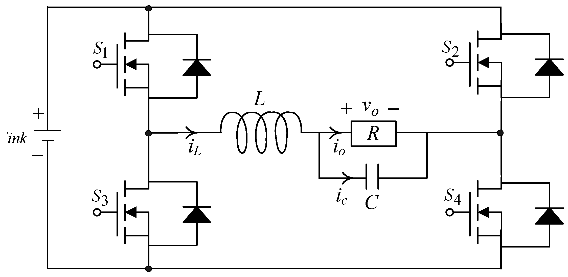
2. System Modeling
3. Control Design
4. Simulation and Experimental Results
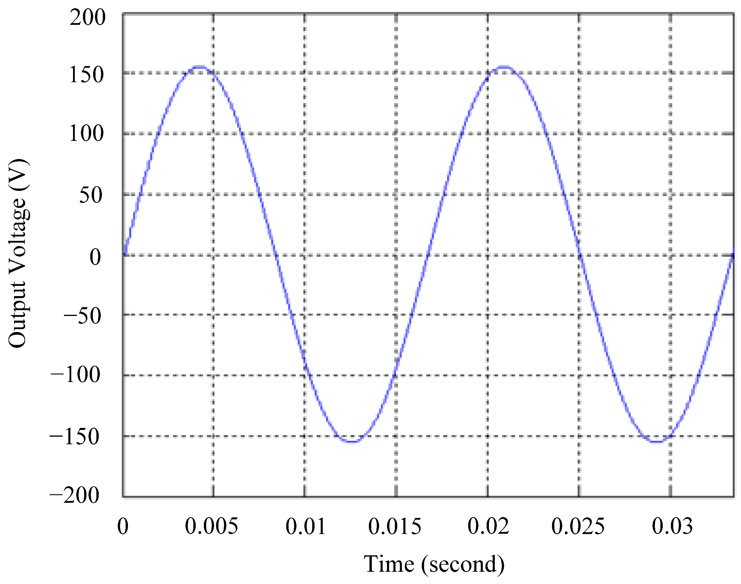
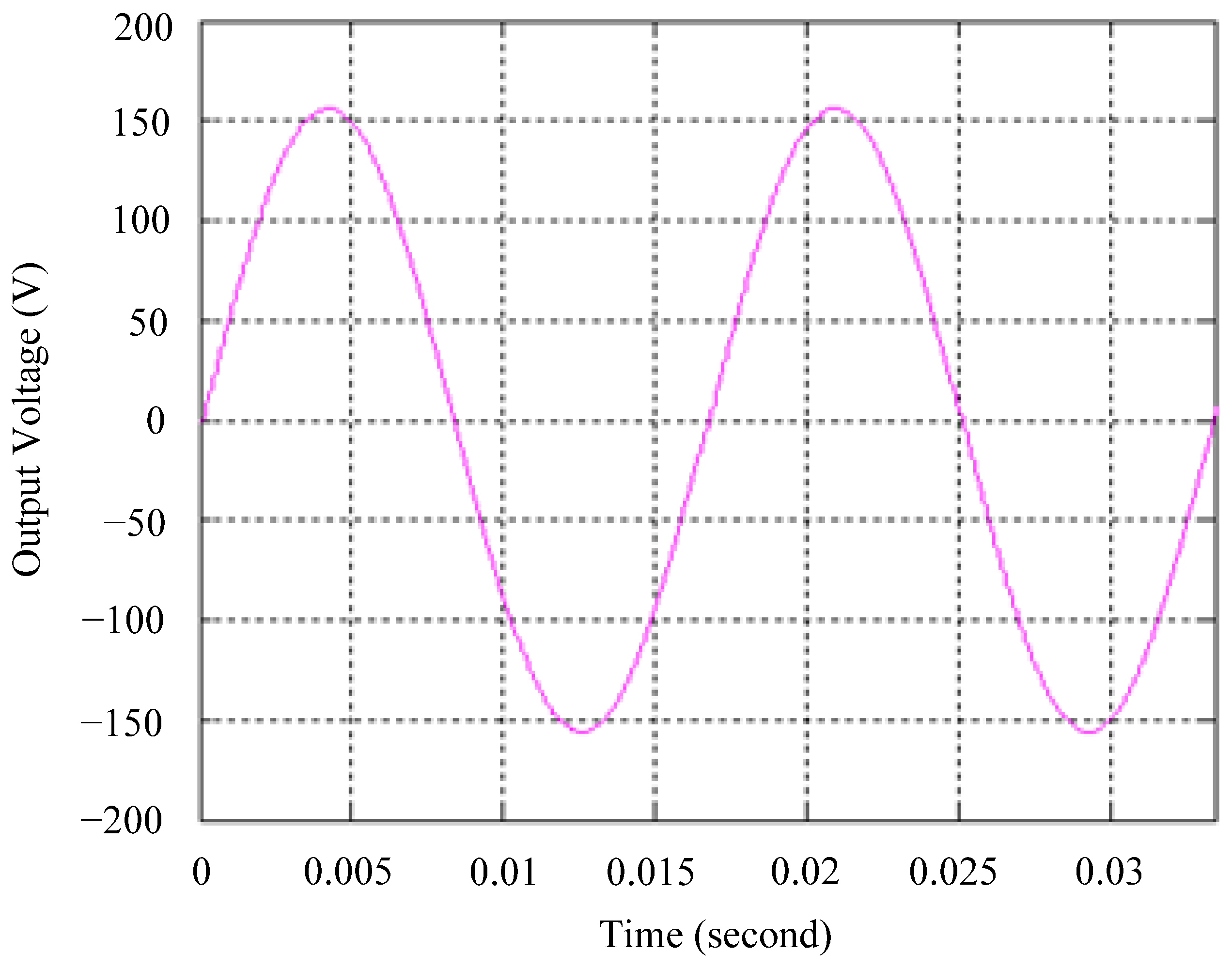
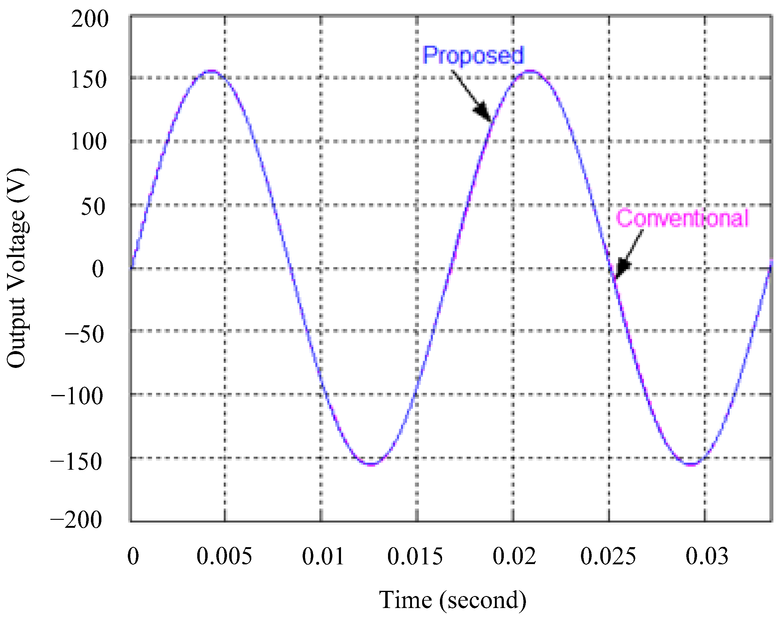
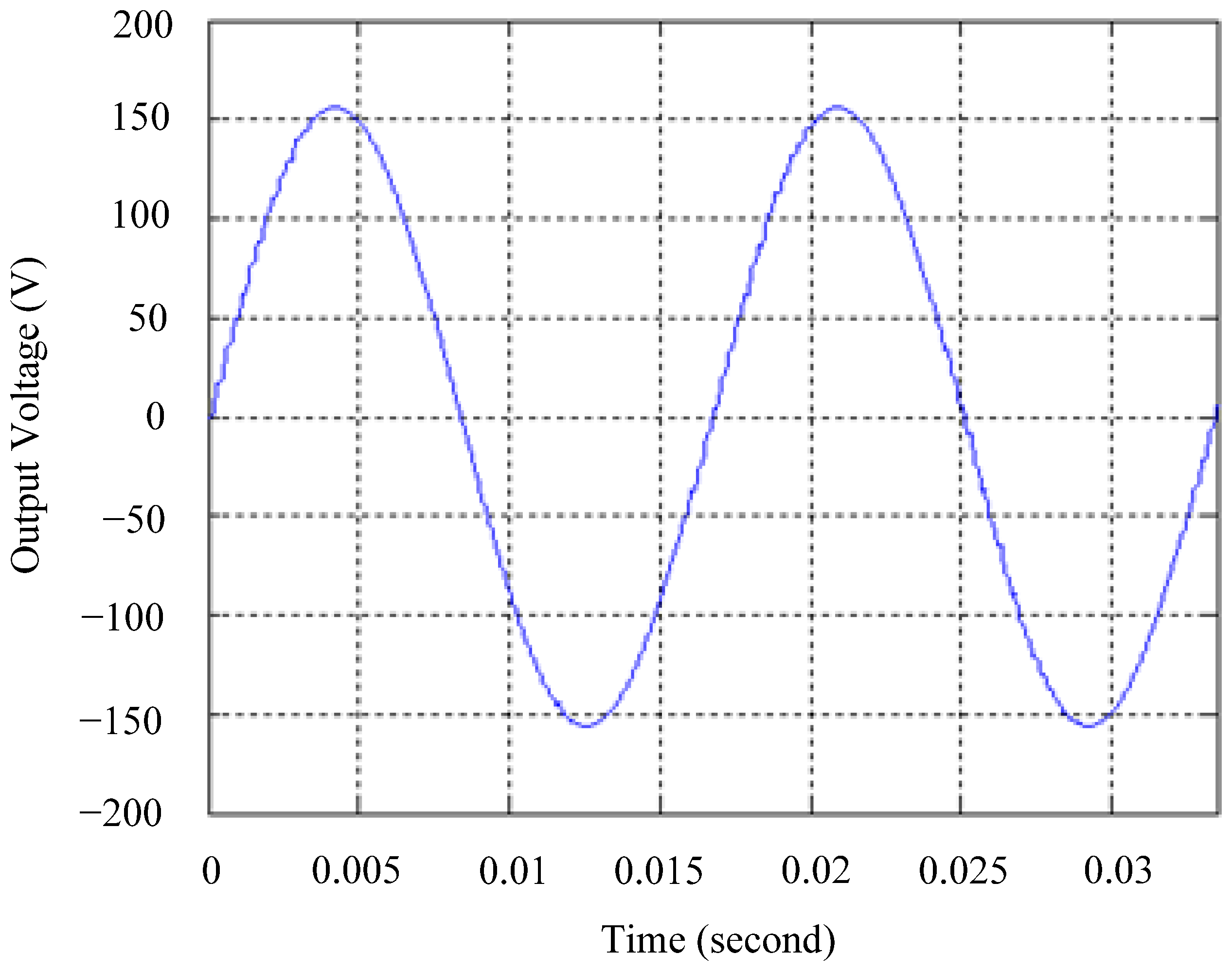
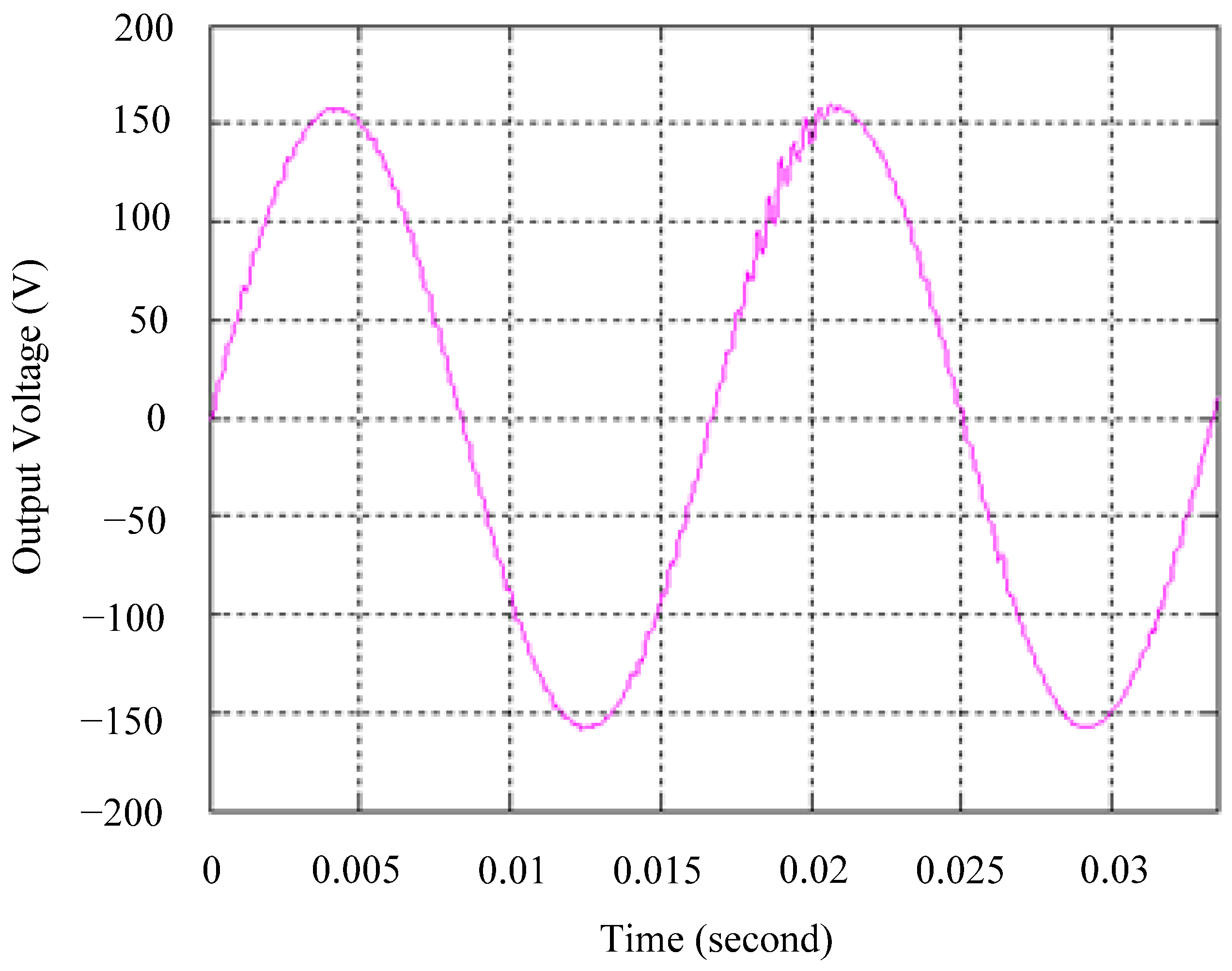
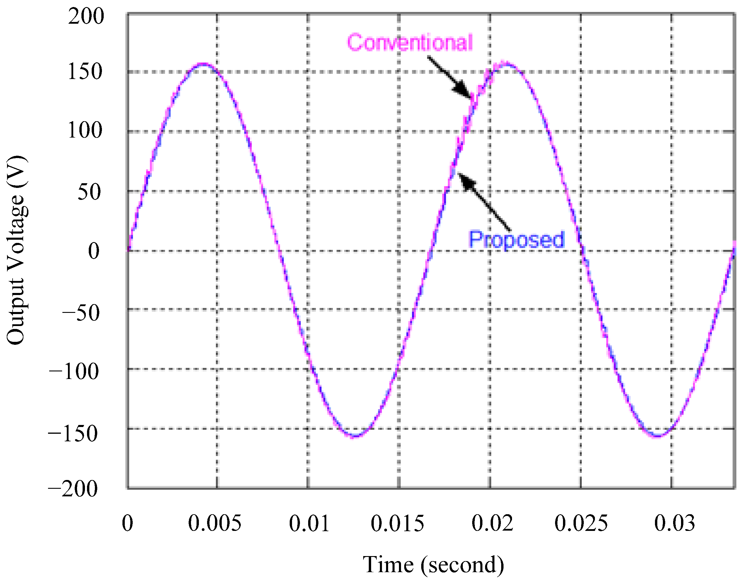
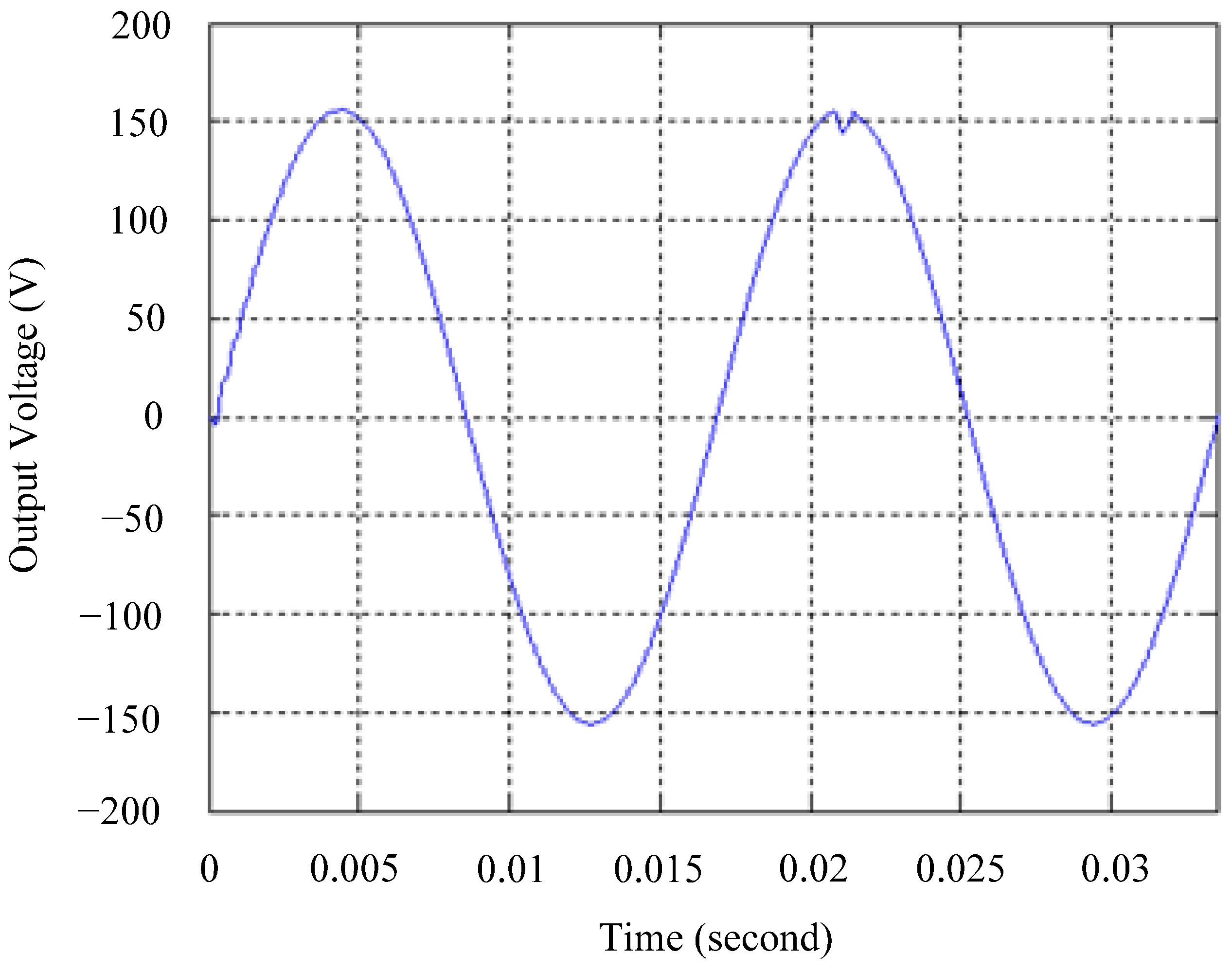
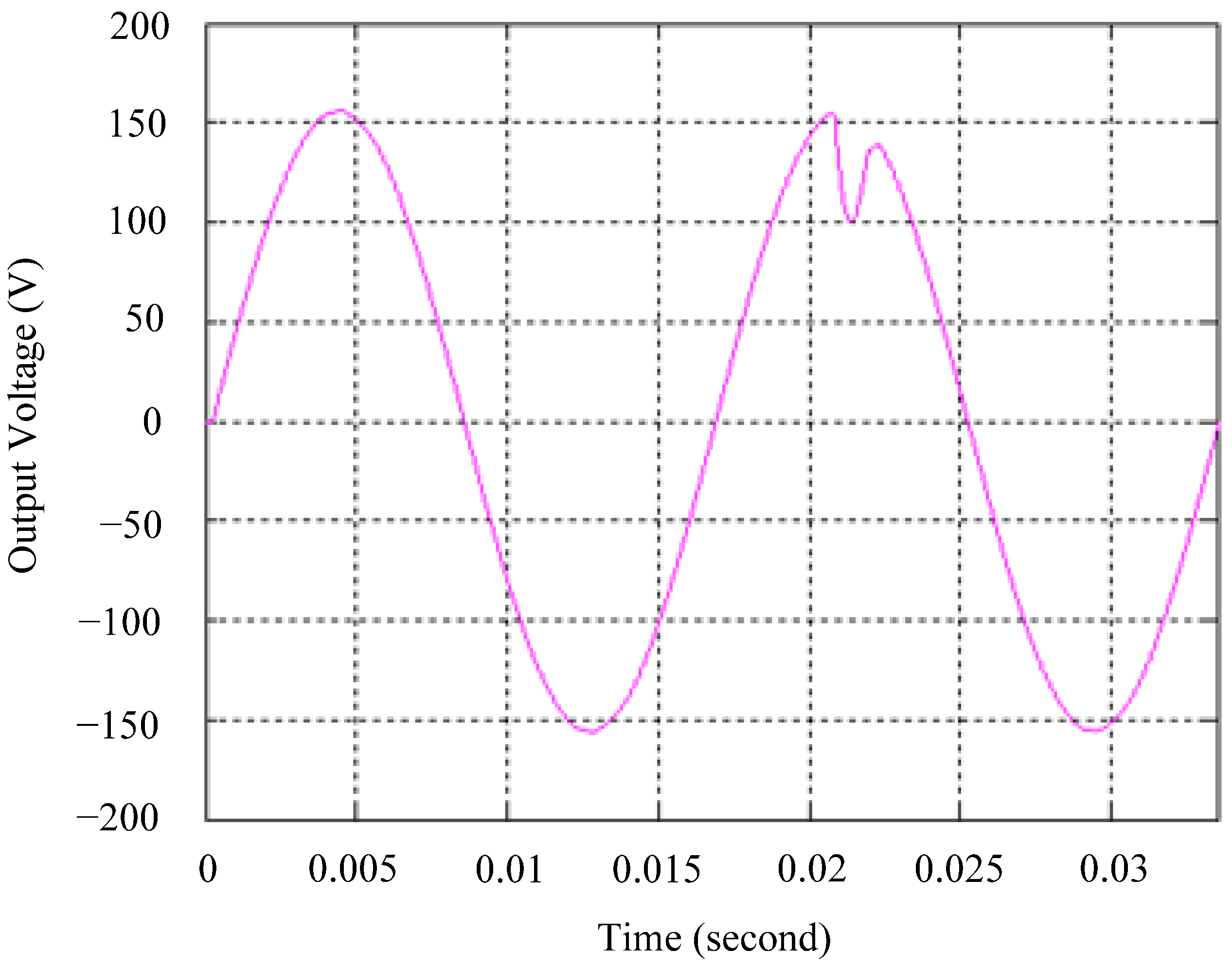
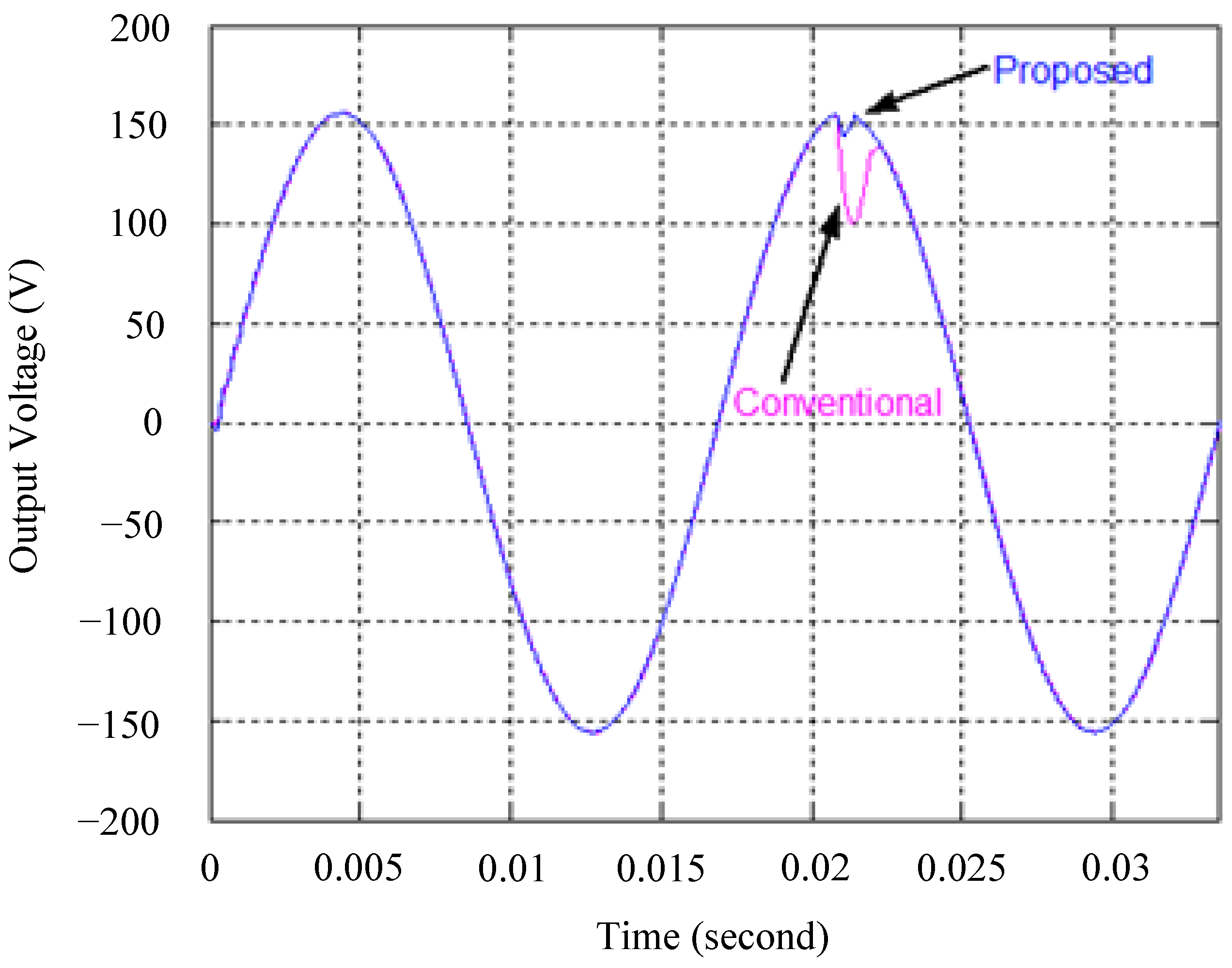
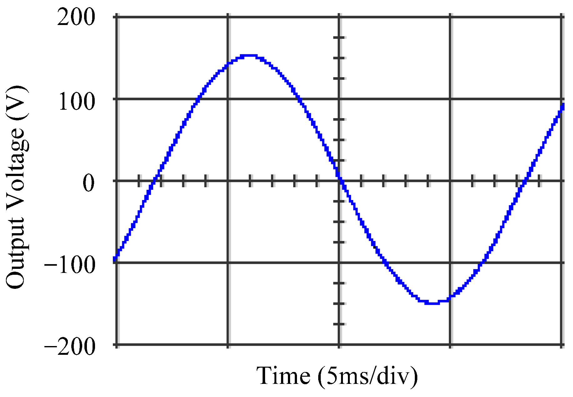
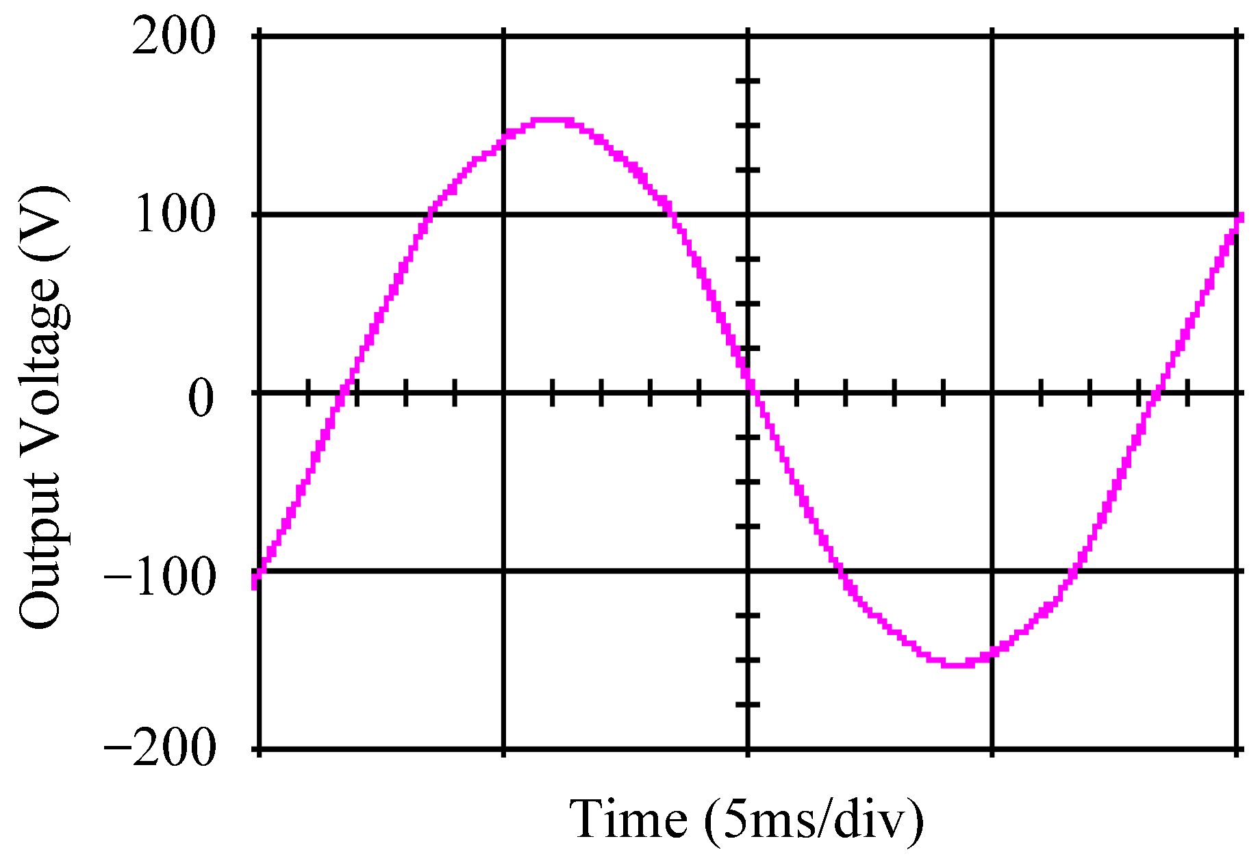
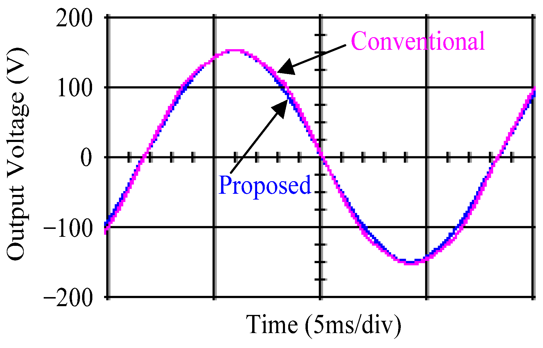
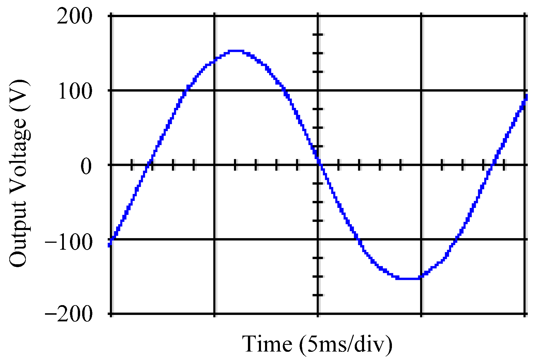
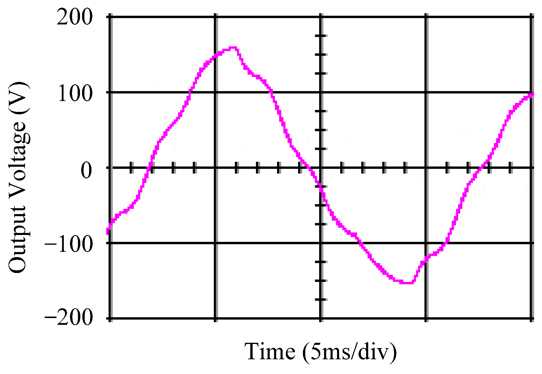
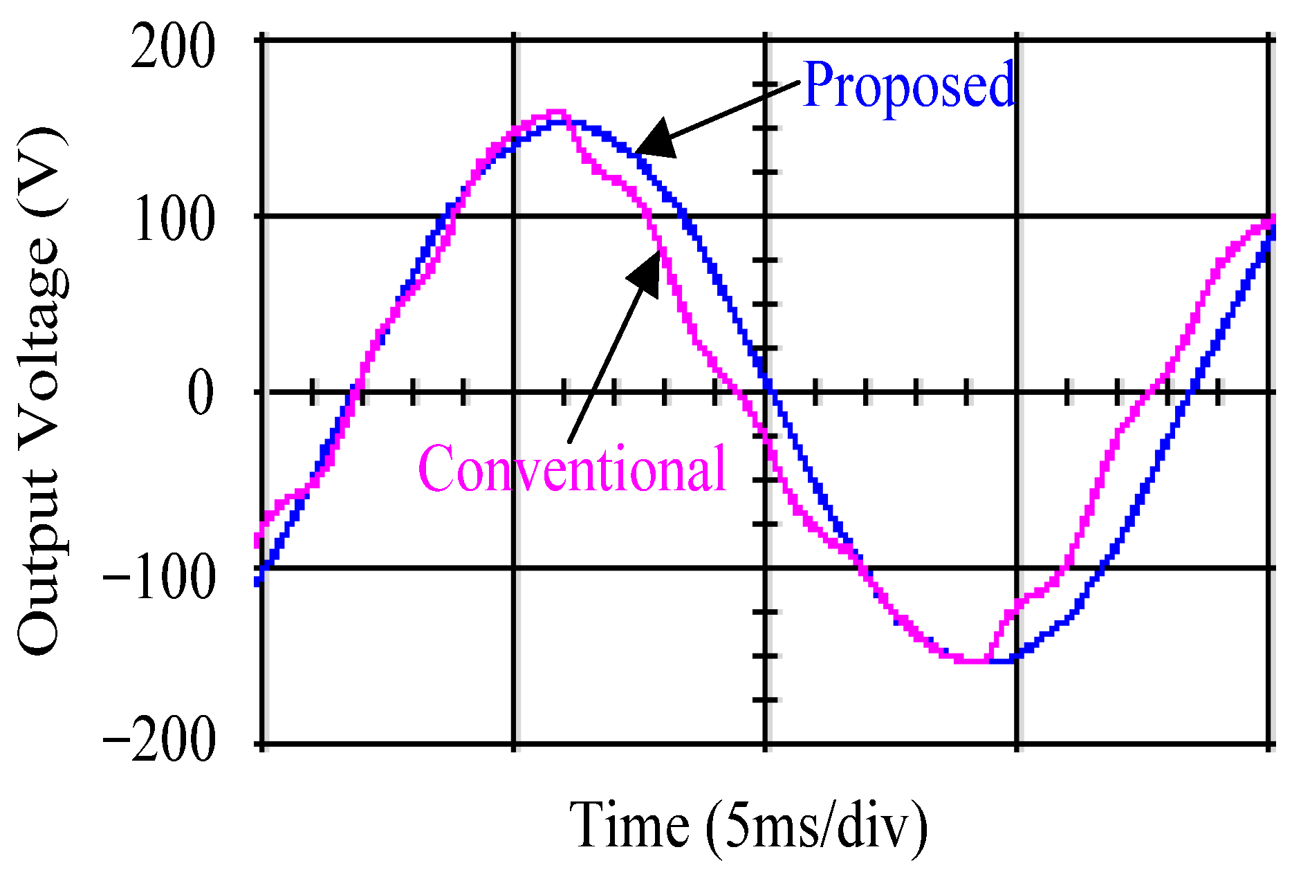
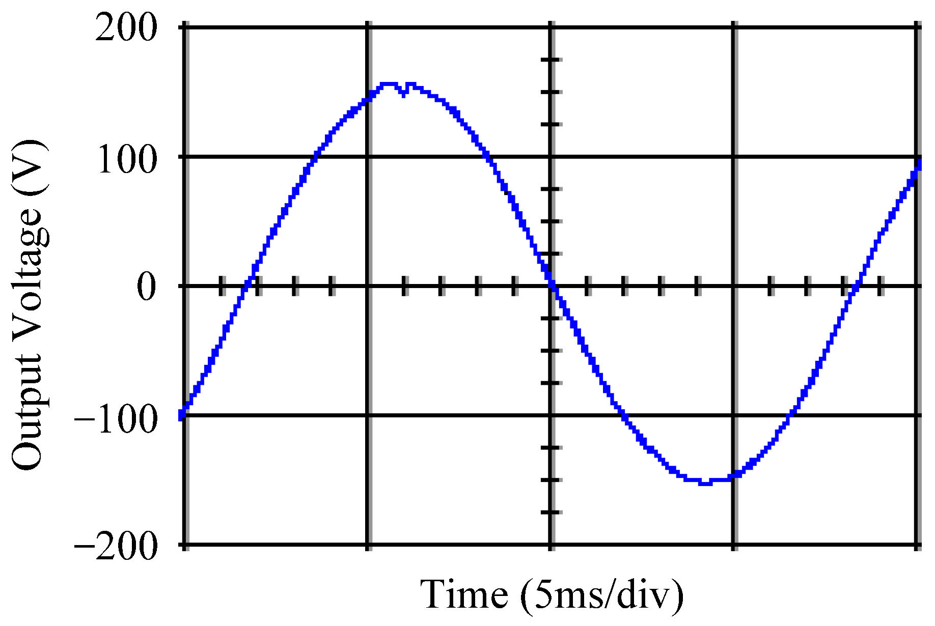
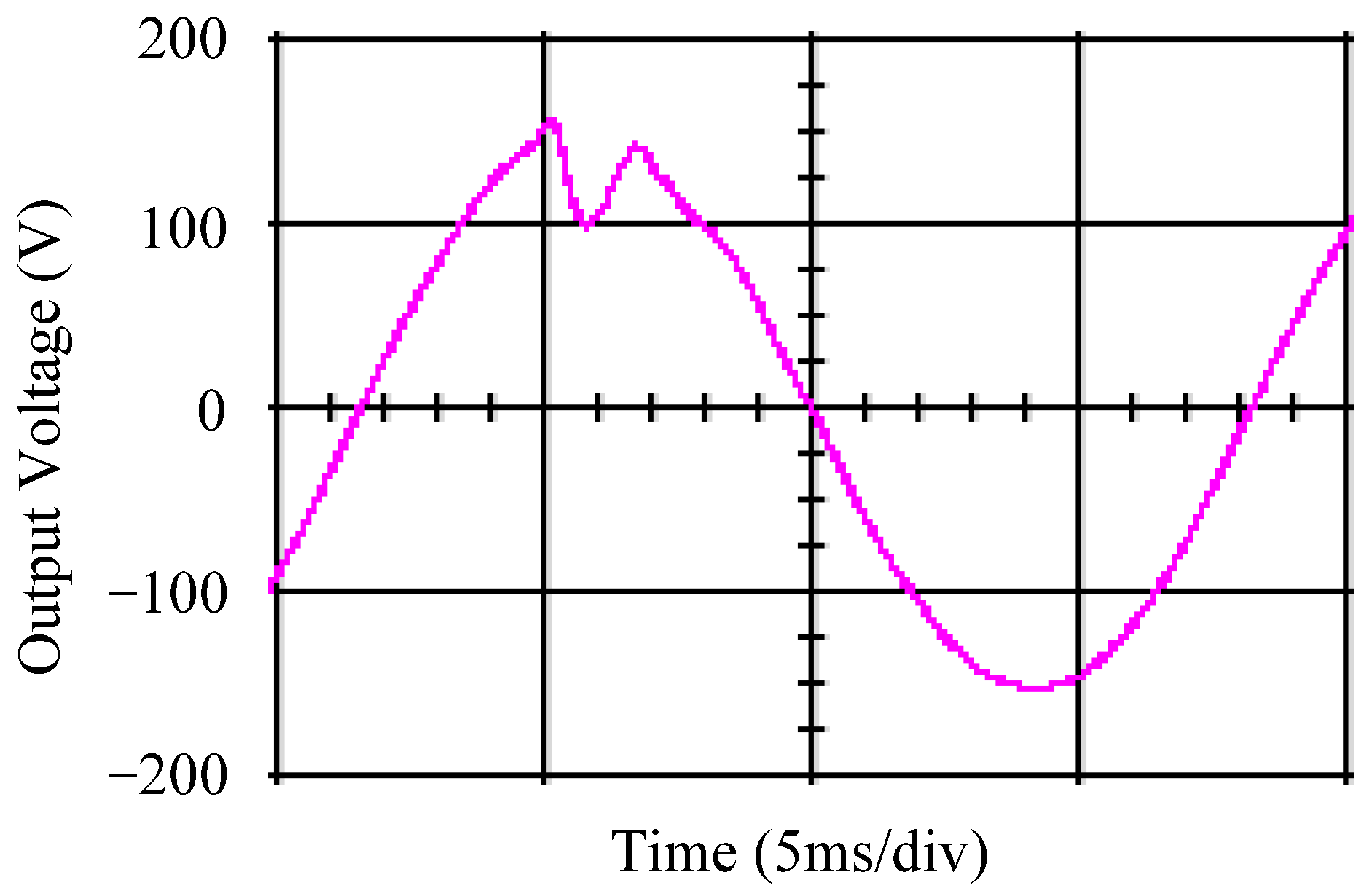
4.1. Simulation Results
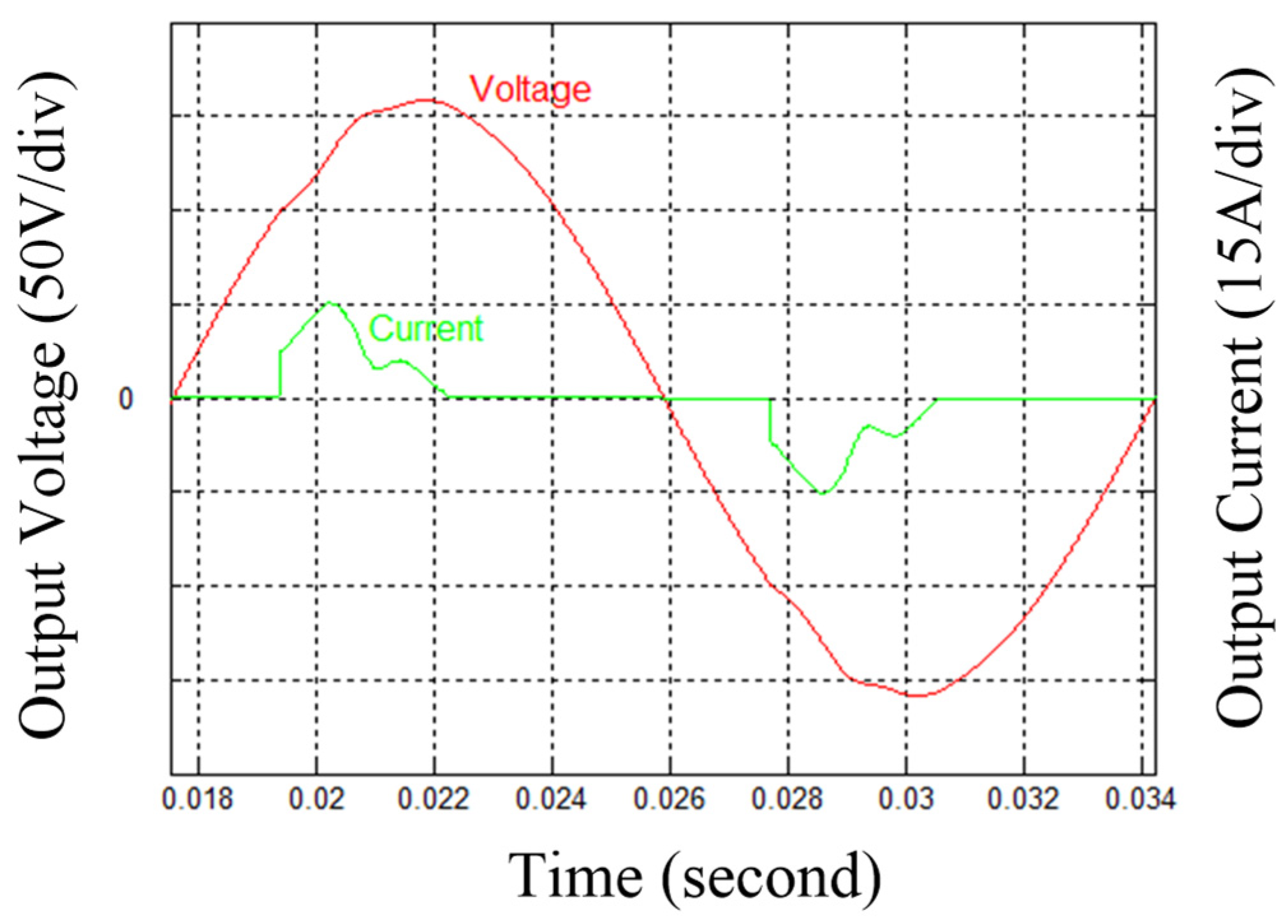
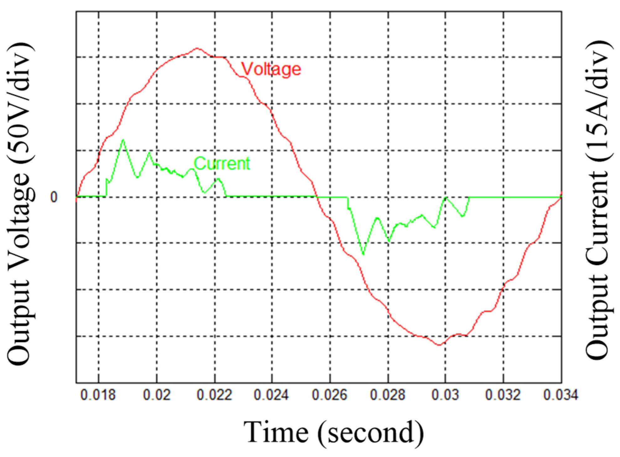
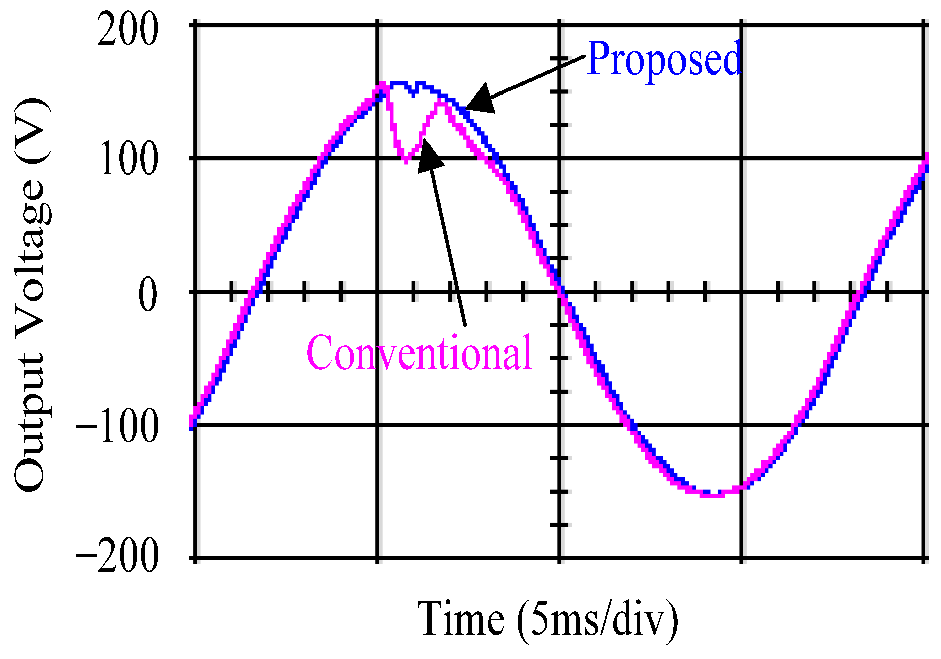
4.2. Experimental Results
5. Discussion and Analysis
6. Conclusions
Author Contributions
Funding
Data Availability Statement
Acknowledgments
Conflicts of Interest
References
- Kumar, L.A.; Alexander, S.A. Power Converters for Electric Vehicles; CRC Press: Boca Raton, FL, USA, 2020. [Google Scholar]
- Kishan, D.; Kannan, R.; Reddy, B.D.; Prabhakaran, P. Power Electronics for Electric Vehicles and Energy Storage: Emerging Technologies and Developments; CRC Press: Boca Raton, FL, USA, 2023. [Google Scholar]
- Jiao, R.; Zhu, J.; Ma, L.; Zhao, Y.; Zhang, B.; Ding, Y.; Gong, C.; Yang, S. High performance deadbeat control for cascaded H-bridge inverter-based variable frequency drive. Int. J. Ind. Electron. Drives 2017, 3, 175–184. [Google Scholar]
- Baroi, S.G.; Samanta, S.; Banerjee, S. Study of Different Types of Inverters and FFT Analysis of Output of SPWM Inverter with Change in Modulating Index and Carrier Frequency. Int. J. Res. Sci. Innov. 2017, 4, 22–29. [Google Scholar]
- Ben-Brahim, L.; Gastli, A.; Ghazi, K. Implementation of iterative learning control based deadtime compensation for PWM inverters. In Proceedings of the 2015 17th European Conference on Power Electronics and Applications (EPE’15 ECCE-Europe), Geneva, Switzerland, 8–10 September 2015; pp. 1–8. [Google Scholar]
- Abrishamifar, A.; Ahmad, A.; Mohamadian, M. Fixed Switching Frequency Sliding Mode Control for Single-Phase Unipolar Inverters. IEEE Trans. Power Electron. 2012, 27, 2507–2514. [Google Scholar] [CrossRef]
- Liu, W.; Hao, X.; Yang, X.; Zhao, M.; Liu, T.; Huang, L. A multi-resonant sliding-mode controller for single-phase grid-connected inverter with LCL-filter. In Proceedings of the 2013 Twenty-Eighth Annual IEEE Applied Power Electronics Conference and Exposition (APEC), Long Beach, CA, USA, 17–21 March 2013; pp. 2541–2546. [Google Scholar]
- Khan, S.; Iqubal, N.; Prasad, S. Voltage Regulator Using Sliding Mode Controller for Inverter Based Islanded Microgrid. Control Appl. Mod. Power Syst. Lect. Notes Electr. Eng. 2022, 870, 141–152. [Google Scholar]
- Sabir, S.; Khaliq, A.; Khan, Q.; Saleem, M. An integral sliding mode based robust voltage tracking control of three phase inverter. In Proceedings of the 2018 1st International Conference on Power, Energy and Smart Grid (ICPESG), Mirpur Azad Kashmir, Pakistan, 9–10 April 2018; pp. 1–6. [Google Scholar]
- Zhang, H.; Xie, R.; Li, Y.; Song, J.; Yuan, C.; Xu, L.; Liang, B.; Ma, R.; Huang, Y. Fast Terminal Sliding Mode Control of DC–DC Boost Converters With Enhanced Disturbance Rejection. IEEE J. Emerg. Sel. Top. Power Electron. 2024, 12, 531–542. [Google Scholar] [CrossRef]
- Li, Z.; Li, Z.; Sun, Z.; Chen, B. A Nonsingular Fast Terminal Sliding Mode Control Scheme for Mecanum-Wheels Omnidirectional Mobile Robots. In Proceedings of the 2023 5th International Conference on Robotics, Intelligent Control and Artificial Intelligence (RICAI), Hangzhou, China, 1–3 December 2024; pp. 50–56. [Google Scholar]
- Gaaloul, A.; Msahli, F. A combined high gain-higher order sliding mode controller for a class of uncertain nonlinear systems. In Proceedings of the 2018 15th International Workshop on Variable Structure Systems (VSS), Graz, Austria, 9–11 July 2018; pp. 215–220. [Google Scholar]
- Chen, Z.; Luo, A.; Wang, H.; Chen, Y.; Li, M.; Huang, Y. Adaptive sliding-mode voltage control for inverter operating in islanded mode in microgrid. Int. J. Electr. Power Energy Syst. 2015, 66, 133–143. [Google Scholar] [CrossRef]
- Hou, B.; Liu, J.; Dong, F.; Wang, M.; Mu, A. Sliding mode control strategy of voltage source inverter based on load current sliding mode observer. In Proceedings of the 2016 IEEE 8th International Power Electronics and Motion Control Conference (IPEMC-ECCE Asia), Hefei, China, 22–26 May 2016; pp. 1–5. [Google Scholar]
- Habib, H.U.R.; Wang, S.; Elmorshedy, M.F.; Waqar, A. Performance Analysis of Combined Model-Predictive and Slide-Mode Control for Power Converters in Renewable Energy Systems. In Proceedings of the 2019 22nd International Conference on Electrical Machines and Systems (ICEMS), Harbin, China, 11–14 August 2019; pp. 2559–2563. [Google Scholar]
- Song, F.; Liu, J.; Zhang, T.; Guo, J.; Tian, S.; Xiong, D. The Grey Forecasting Model for the Medium-and Long-Term Load Forecasting. J. Phys. Conf. Ser. 2020, 1654, 1–7. [Google Scholar] [CrossRef]
- Zeng, B.; Shi, Z. Grey Prediction Methods and Its Applications; Springer: Singapore, 2024. [Google Scholar]
- Song, J.; Hu, M. The fractional accumulative time-delay GM (1, N) model and its application. In Proceedings of the 2021 IEEE International Conference on Systems, Man, and Cybernetics (SMC), Melbourne, Australia, 17–20 October 2022; pp. 1577–1584. [Google Scholar]
- Zhang, M.; Cheng, C. A fractional-order multivariable grey model and its application in predicting pollution emissions. In Proceedings of the 2024 IEEE 4th International Conference on Electronic Technology, Communication and Information (ICETCI), Changchun, China, 24–26 May 2024; pp. 44–48. [Google Scholar]
- Li, A.S.; Gao, F.; Wang, M.; Lin, B.Y. A Parameter Estimation of Fractional Order Multivariate Grey Model with Time-delay Based on Adaptive Dynamic Cat Swarm Optimization. In Proceedings of the 2019 Chinese Control And Decision Conference (CCDC), Nanchang, China, 3–5 June 2019; pp. 4249–4253. [Google Scholar]
- Yang, X.; Cui, T.; Shou, M. A Fractional Grey Multivariable Model for Modeling Fresh Graduates’ Career Choice. J. Math. 2021, 2021, 8237600. [Google Scholar] [CrossRef]
- IEEE Standard 519-1992; IEEE 519 Recommended Practice and Requirements for Harmonic Control in Electric Power Systems. IEEE: New York, NY, USA, 1992.
- IEEE Standard 519-2014; IEEE 519 Recommended Practice and Requirements for Harmonic Control in Electric Power Systems. IEEE: New York, NY, USA, 2014.
- IEEE Standard 1159–2019; IEEE Recommended Practice for Monitoring Electric Power Quality. IEEE: New York, NY, USA, 2019.
- Kim, J.; Choi, J.; Hong, H. Output LC Filter Design of Voltage Source Inverter Considering the Performance of Controller. In Proceedings of the 2000 International Conference on Power System Technology, Perth, WA, Australia, 4–7 December 2000; pp. 1–6. [Google Scholar]
- Dahono, P.A.; Purwadi, A.; Qamaruzzaman. An LC Filter Design Method for Single-Phase PWM Inverters. In Proceedings of the 1995 Power Electronics and Drive Systems, Singapore, 21–24 February 1995; pp. 571–576. [Google Scholar]
- Liu, Y.C.; Zhang, Q.J.; Wang, C.; Wang, N. A Control Strategy for Microgrid Inverters Based on Adaptive Three-Order Sliding Mode and Optimized Droop Controls. Electr. Power Syst. Res. 2014, 117, 192–201. [Google Scholar] [CrossRef]
- Zhou, M.H.; Wu, X.G.; Cai, W.; Xu, W.; Xu, L.; Chi, Y. Full-order Terminal Sliding mode Control for Virtual Synchronous Generator based Inverter. In Proceedings of the 47th Annual Conference of the IEEE Industrial Electronics Society, Toronto, ON, Canada, 13–16 October 2021; pp. 1–5. [Google Scholar]
- Sun, W.; Xu, Y.F. Research on China’s Energy Supply and Demand Using an Improved Grey-Markov Chain Model Based on Wavelet Transform. Energy 2017, 118, 969–984. [Google Scholar]
- Liu, Q.; Yang, C.Y.; Lin, L. Deformation Prediction of a Deep Foundation Pit Based on the Combination Model of Wavelet Transform and Gray BP Neural Network. Math. Probl. Eng. 2021, 2021, 2161254. [Google Scholar] [CrossRef]

| Methods | Characteristics | Advantages | Disadvantages |
|---|---|---|---|
| Proposed control technique | Strong insensitivity | Finite state convergence time, Fast calculation, and no singularities | Slightly higher hardware realization cost |
| Deadbeat control technology [3] | Constant switching frequency | Fast dynamic response, and short settling time. | Dependent on the accuracy of the parameters |
| Fast fourier transform analysis [4] | Overcoming disturbances effectively | Processing large amounts of data | Computational complexity |
| Iterative learning control [5] | Attenuating repeating disturbances | Improvement of tracking accuracy | Long time calculation |
| Parameters | Value |
|---|---|
| DC-link voltage () | 200 V |
| AC output voltage () | 110 Vrms |
| Power of inverter | 500 W |
| Frequency of AC output-voltage | 60 Hz |
| Filter inductor () | 1 mH |
| Filter capacitor () | 20 μF |
| Resistive load () | 12 ohm |
| Switching frequency | 36 kHz |
| Proposed Control Technique | |||
|---|---|---|---|
| Simulations | Resistive loading | Step load changing | Filter parameters varying |
| %THD | Voltage droop | %THD | |
| 0.025% | 10.612 volts | 0.040% | |
| Conventional TA | |||
| Simulations | Resistive loading | Step load changing | Filter parameters varying |
| %THD | Voltage droop | %THD | |
| 0.031% | 56.133 volts | 5.854% | |
| Proposed control technique | |||
| Experiments | Resistive loading | Step load changing | Filter parameters varying |
| %THD | Voltage droop | %THD | |
| 0.027% | 10.785 volts | 0.042% | |
| Conventional TA | |||
| Experiments | Resistive loading | Step load changing | Filter parameters varying |
| %THD | Voltage droop | %THD | |
| 0.039% | 58.741 volts | 6.137% | |
Disclaimer/Publisher’s Note: The statements, opinions and data contained in all publications are solely those of the individual author(s) and contributor(s) and not of MDPI and/or the editor(s). MDPI and/or the editor(s) disclaim responsibility for any injury to people or property resulting from any ideas, methods, instructions or products referred to in the content. |
© 2024 by the authors. Published by MDPI on behalf of the World Electric Vehicle Association. Licensee MDPI, Basel, Switzerland. This article is an open access article distributed under the terms and conditions of the Creative Commons Attribution (CC BY) license (https://creativecommons.org/licenses/by/4.0/).
Share and Cite
Chang, E.-C.; Tseng, Y.-W.; Cheng, C.-A. Control Design of Fractional Multivariable Grey Model-Based Fast Terminal Attractor for High Efficiency Pure Sine Wave Inverters in Electric Vehicles. World Electr. Veh. J. 2024, 15, 556. https://doi.org/10.3390/wevj15120556
Chang E-C, Tseng Y-W, Cheng C-A. Control Design of Fractional Multivariable Grey Model-Based Fast Terminal Attractor for High Efficiency Pure Sine Wave Inverters in Electric Vehicles. World Electric Vehicle Journal. 2024; 15(12):556. https://doi.org/10.3390/wevj15120556
Chicago/Turabian StyleChang, En-Chih, Yuan-Wei Tseng, and Chun-An Cheng. 2024. "Control Design of Fractional Multivariable Grey Model-Based Fast Terminal Attractor for High Efficiency Pure Sine Wave Inverters in Electric Vehicles" World Electric Vehicle Journal 15, no. 12: 556. https://doi.org/10.3390/wevj15120556
APA StyleChang, E.-C., Tseng, Y.-W., & Cheng, C.-A. (2024). Control Design of Fractional Multivariable Grey Model-Based Fast Terminal Attractor for High Efficiency Pure Sine Wave Inverters in Electric Vehicles. World Electric Vehicle Journal, 15(12), 556. https://doi.org/10.3390/wevj15120556