
Simulation and Analysis of the Energy Consumption of a Fuel Cell Hybrid Electric Vehicle


Abstract
1. Introduction
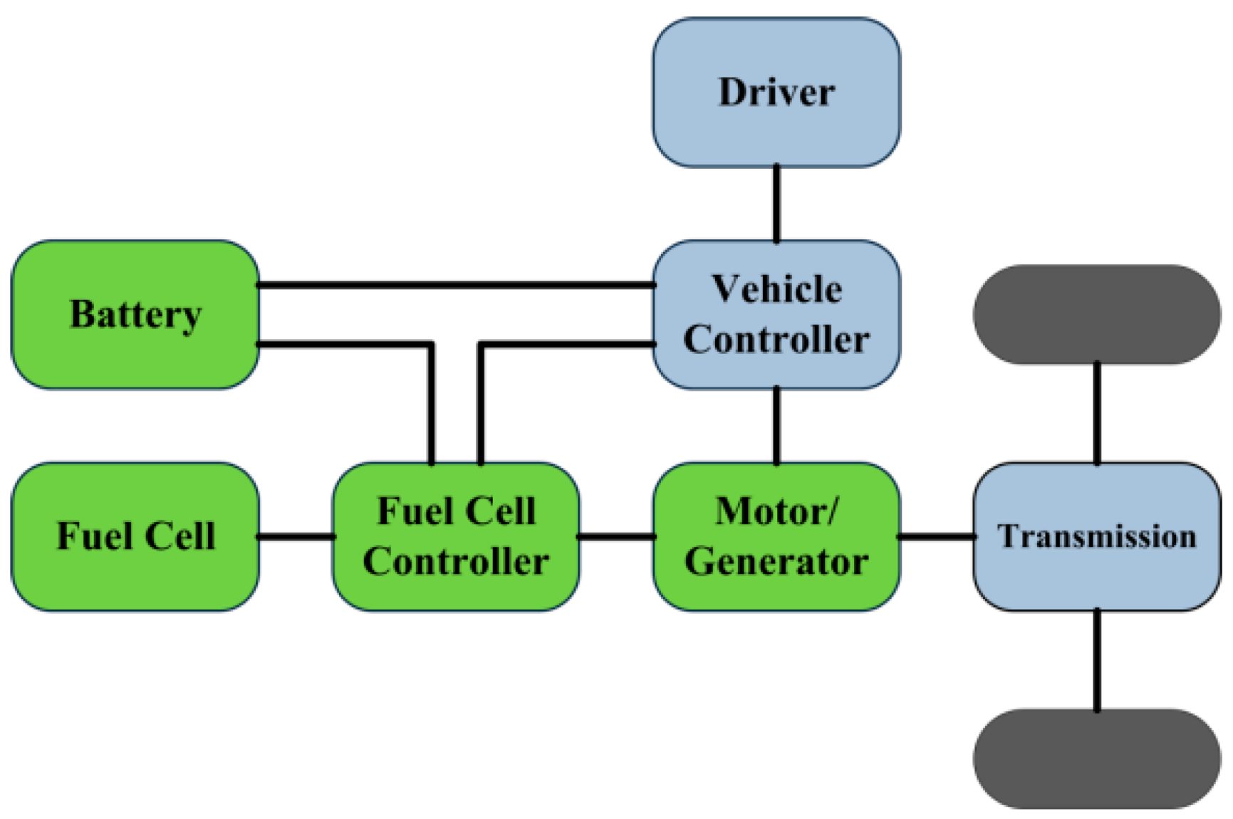
2. Components of a Fuel Cell Hybrid Electric Vehicle
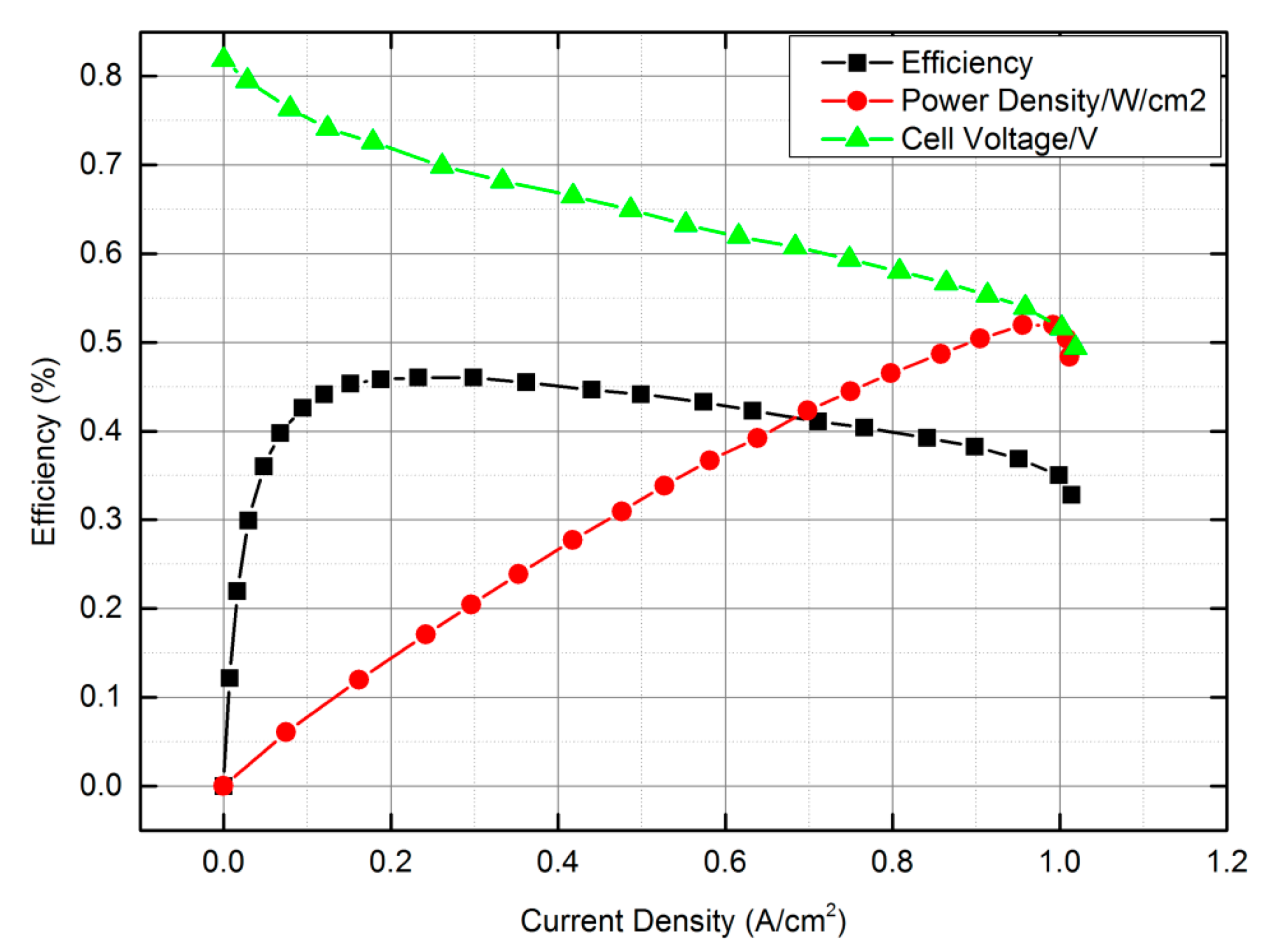
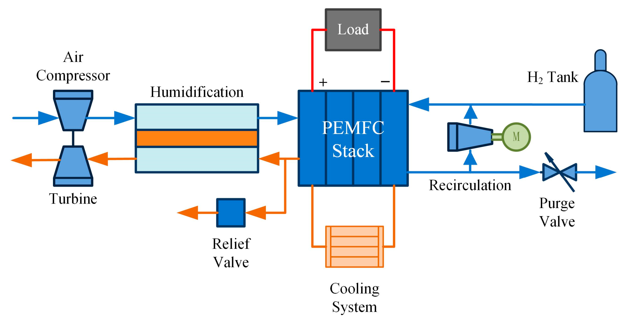
2.1. Fuel Cell
2.2. Battery
2.3. Permanent Magnet Synchronous Motor
2.4. Energy Control Strategy
3. Simulations
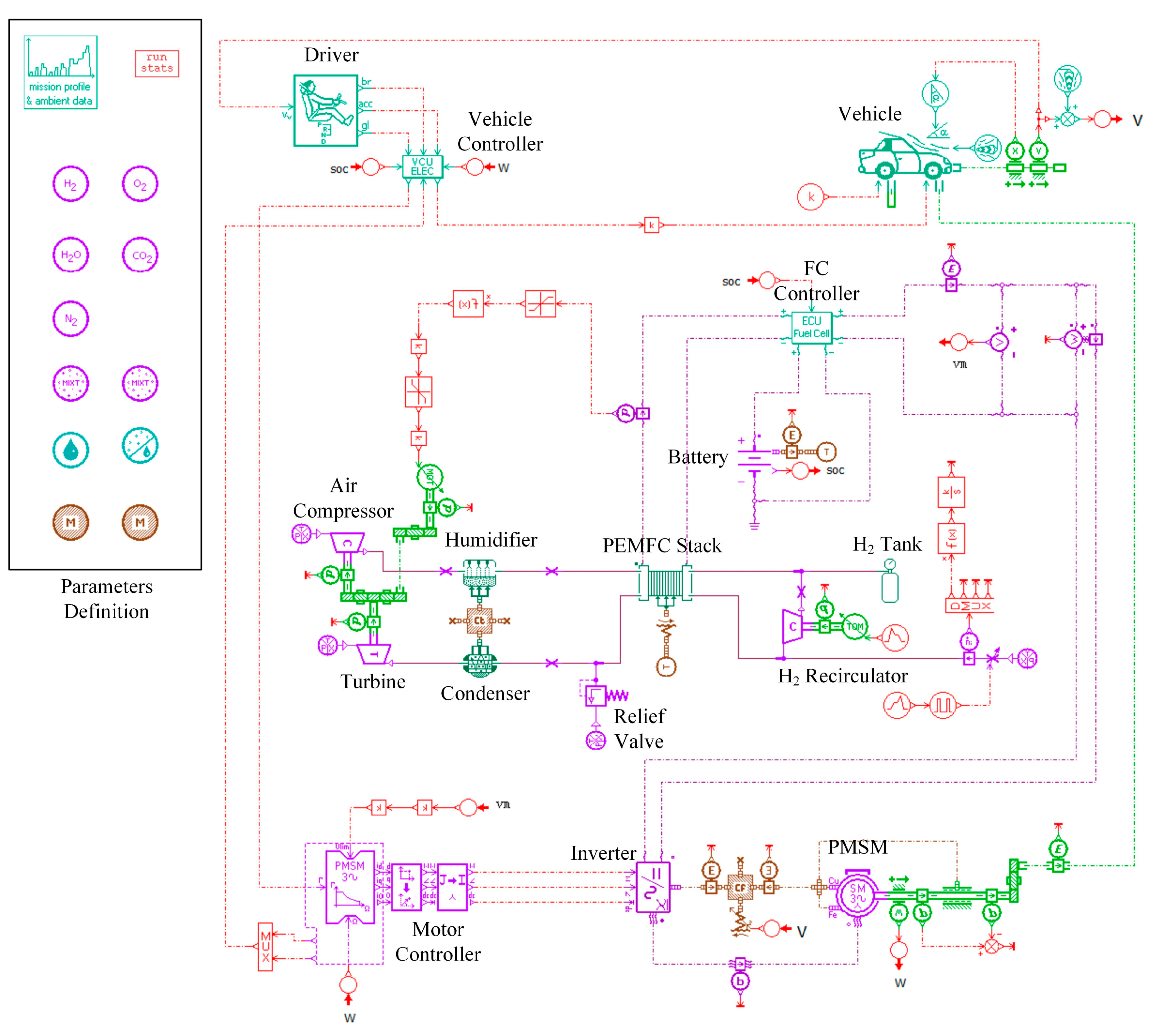
3.1. Simulation Environment
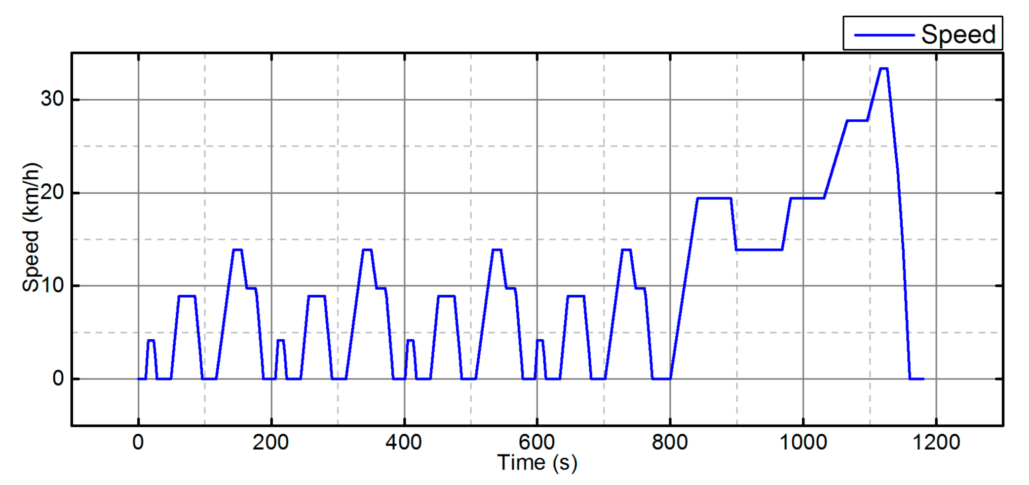
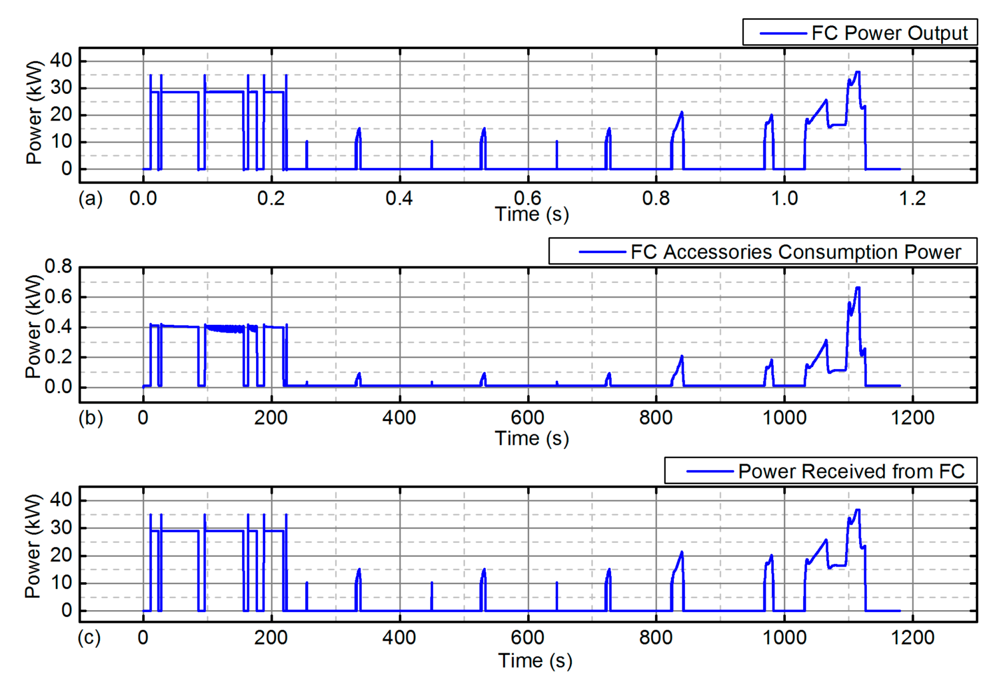
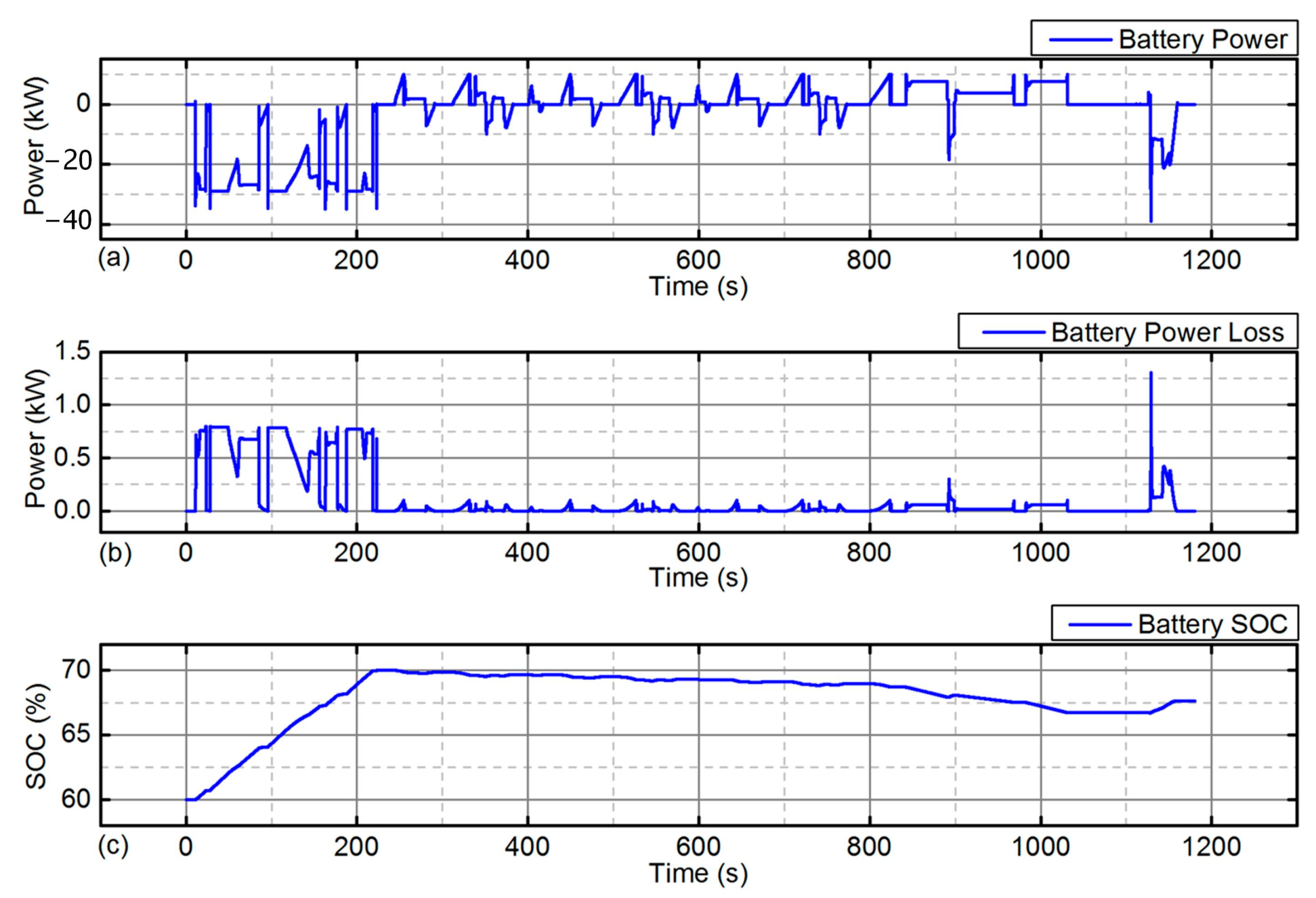
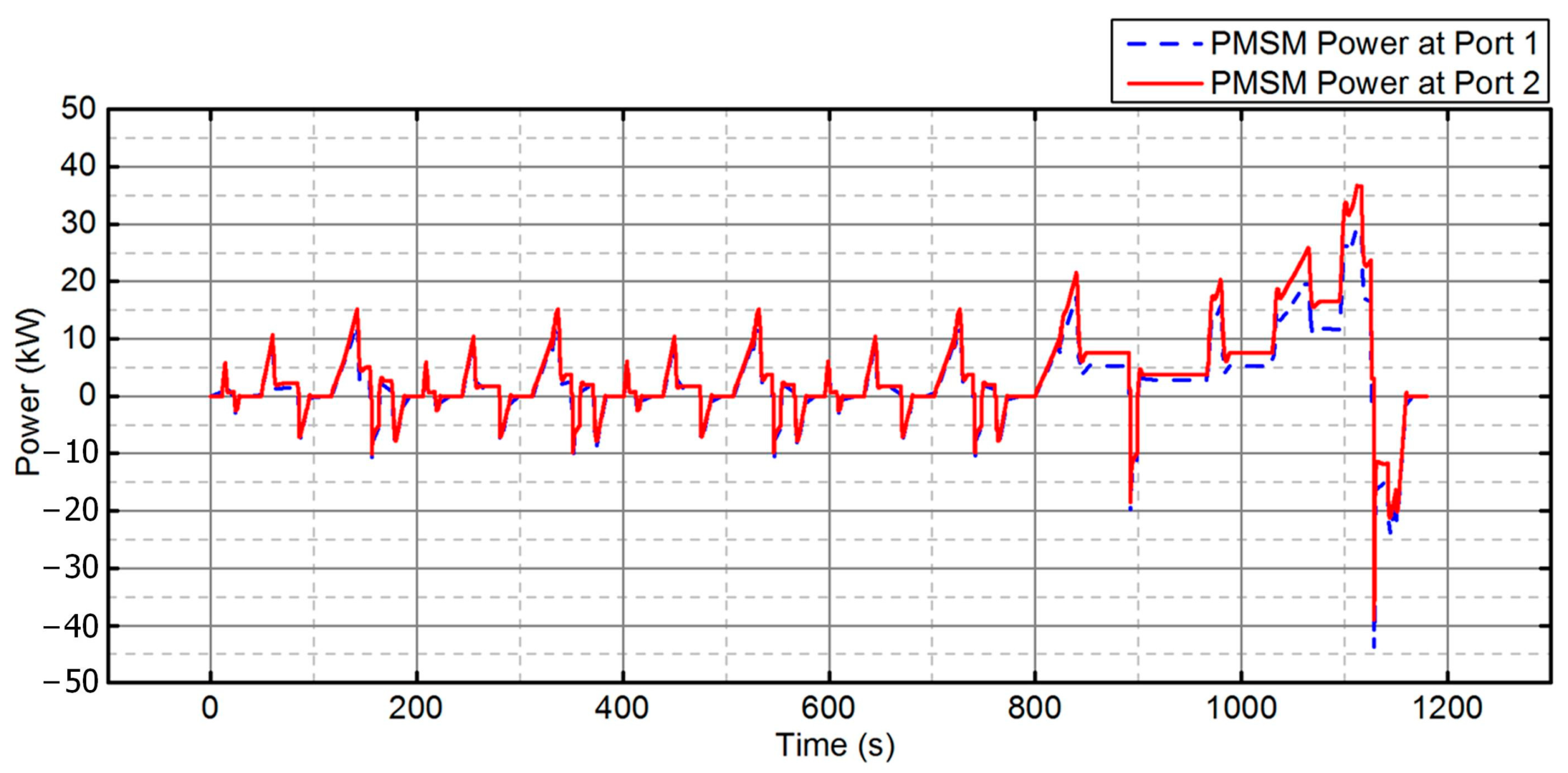
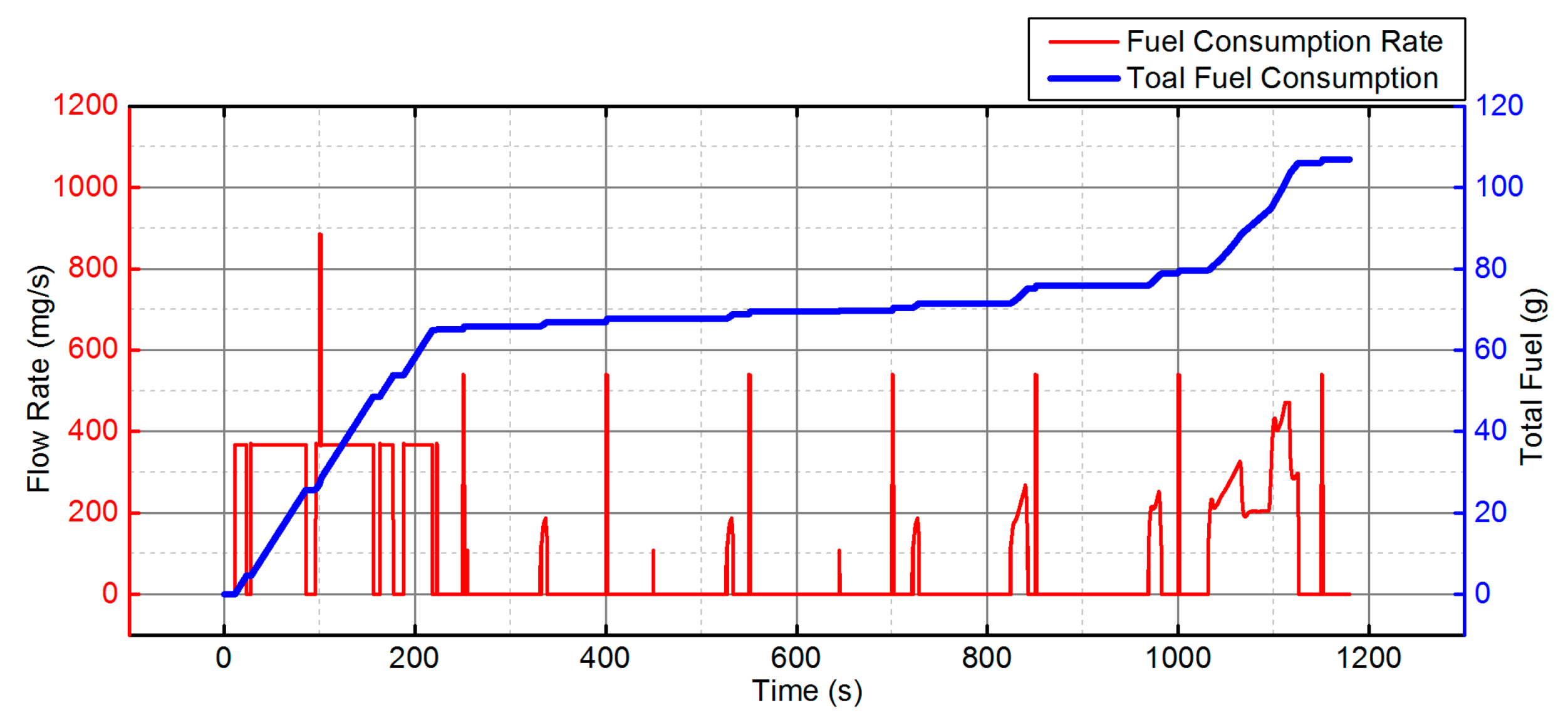
3.2. Simulation Process of a Single NEDC Cycle
4. Simulation Results Analysis
4.1. The Influence of Variations in a Single Parameter
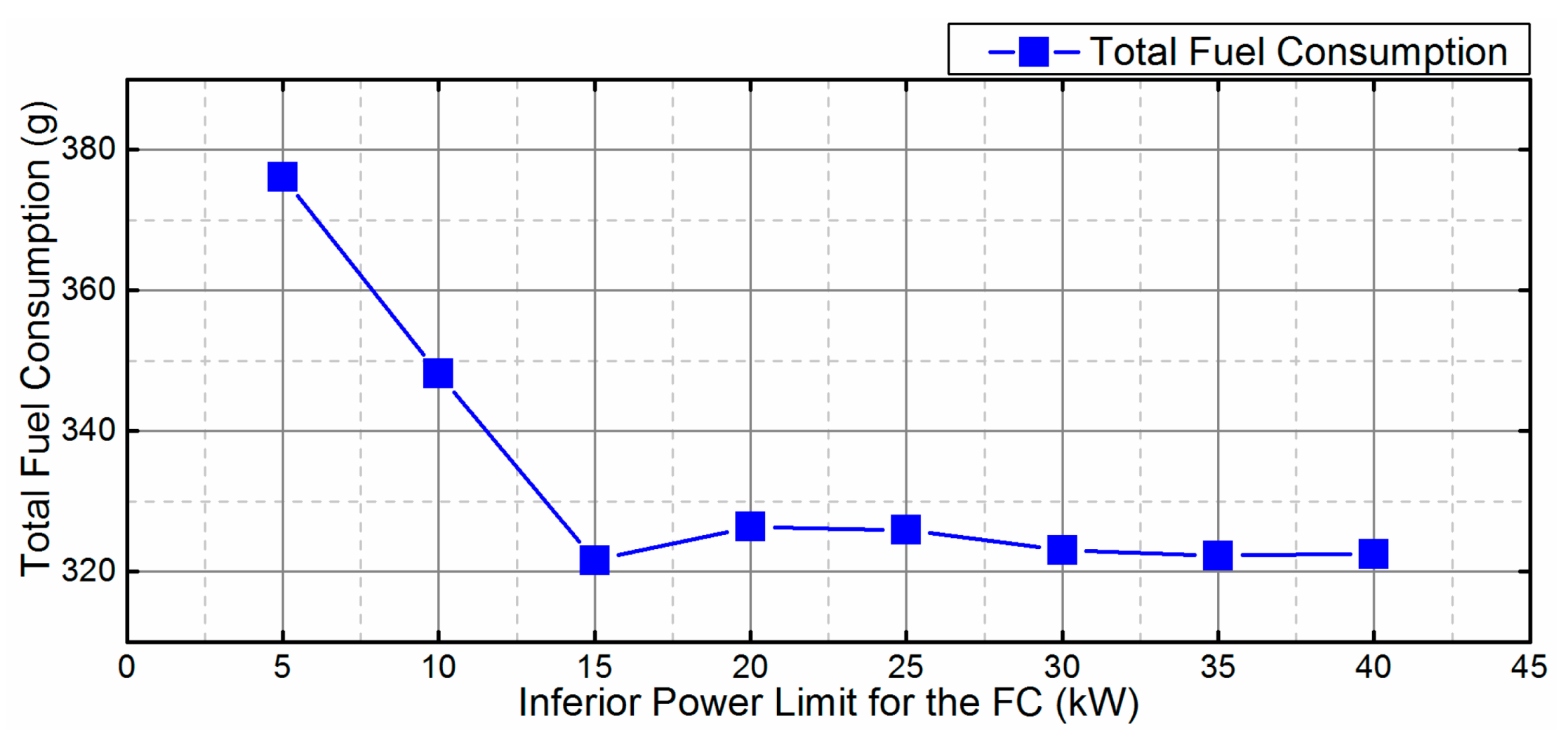
4.1.1. IPLFC
4.1.2. SIB
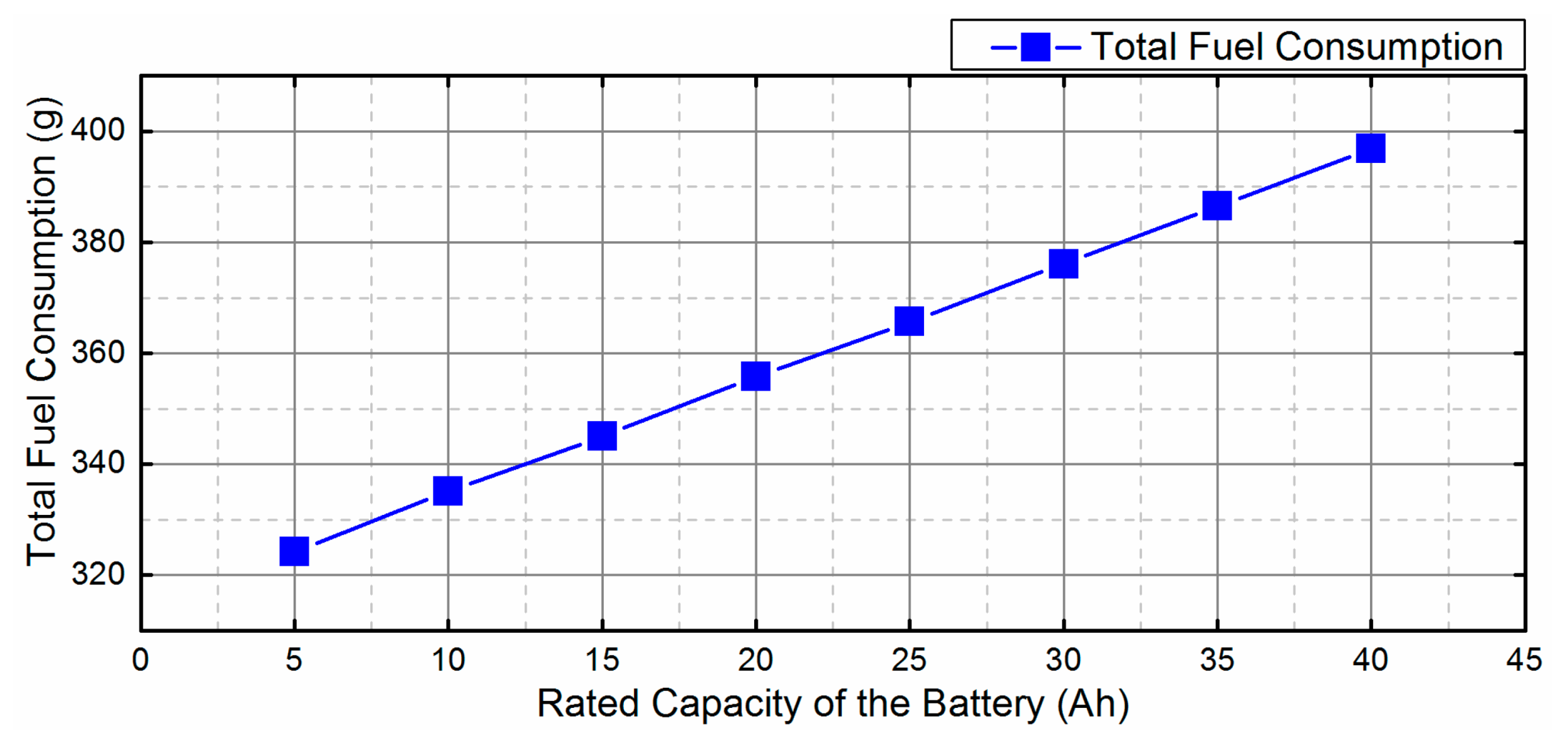
4.1.3. RCB
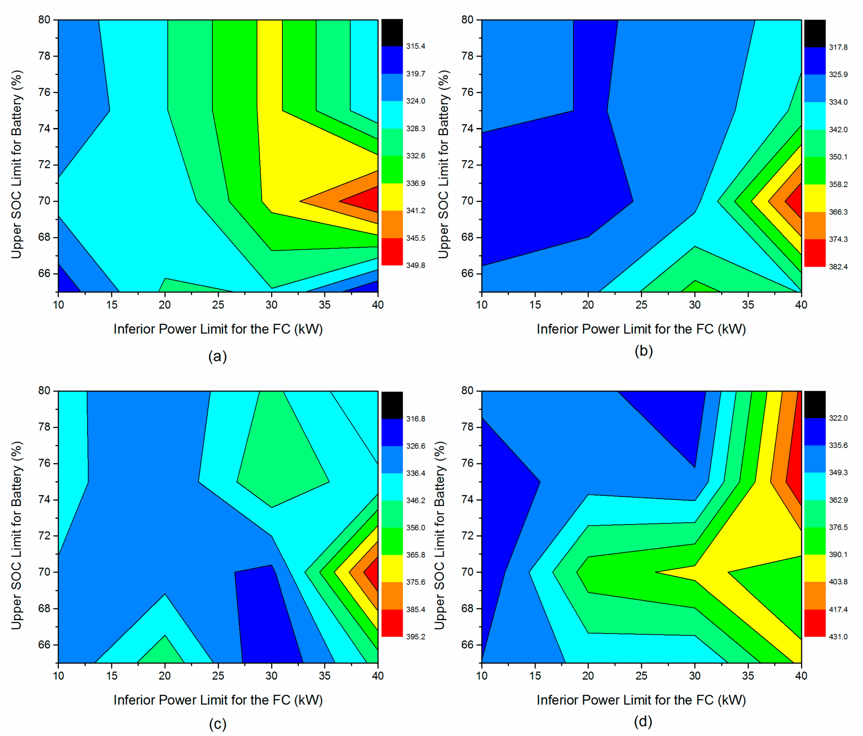
4.2. The Influence of Multiparameter Variations
5. Conclusions
Author Contributions
Funding
Data Availability Statement
Acknowledgments
Conflicts of Interest
References
- Tie, S.F.; Tan, C.W. A review of energy sources and energy management system in electric vehicles. Renew. Sustain. Energy Rev. 2013, 20, 82–102. [Google Scholar] [CrossRef]
- Ge, L.; Quan, L.; Li, Y.; Zhang, X.; Yang, J. A novel hydraulic excavator boom driving system with high efficiency and potential energy regeneration capability. Energy Convers. Manag. 2018, 166, 308–317. [Google Scholar] [CrossRef]
- Khalil, A.; Rajab, Z.; Alfergani, A.; Mohamed, O. The impact of the time delay on the load frequency control system in microgrid with plug-in-electric vehicles. Sustain. Cities Soc. 2017, 35, 365–377. [Google Scholar] [CrossRef]
- He, X.; Liu, H.; He, S.; Hu, B.; Xiao, G. Research on the energy efficiency of energy regeneration systems for a battery-powered hydrostatic vehicle. Energy 2019, 178, 400–418. [Google Scholar] [CrossRef]
- He, X.; Jiang, Y. Review of hybrid electric systems for construction machinery. Autom. Constr. 2018, 92, 286–296. [Google Scholar] [CrossRef]
- Cawthorne, W.R.; Hubbard, G.A. Method of Determining Engine Output Power in a Hybrid Electric Vehicle. U.S. Patent US007653474B2, 26 January 2010. [Google Scholar]
- Weldon, P.; Morrissey, P.; O’Mahony, M. Long-term cost of ownership comparative analysis between electric vehicles and internal combustion engine vehicles. Sustain. Cities Soc. 2018, 39, 578–591. [Google Scholar] [CrossRef]
- Jiang, Y.; He, X. Overview of Applications of the Sensor Technologies for Construction Machinery. IEEE Access 2020, 8, 110324–110335. [Google Scholar] [CrossRef]
- Zhang, J.; Yan, S.; Qu, H. Recent progress in magnesium hydride modified through catalysis and nanoconfinement. Int. J. Hydrogen Energy 2018, 43, 1545–1565. [Google Scholar] [CrossRef]
- Ge, L.; Quan, L.; Zhang, X.; Dong, Z.; Yang, J. Power matching and energy efficiency improvement of hydraulic excavator driven with speed and displacement variable power source. Chin. J. Mech. Eng. 2019, 32, 100. [Google Scholar] [CrossRef]
- Wang, X.; Quan, L.; Luan, S.; Xu, X. Dynamic and Static Characteristics of Double Push Rods Electromechanical Converter. Chin. J. Mech. Eng. 2019, 32, 62. [Google Scholar] [CrossRef]
- Cigolotti, V.; Genovese, M.; Fragiacomo, P. Comprehensive review on fuel cell technology for stationary applications as sustainable and efficient poly-generation energy systems. Energies 2021, 14, 4963. [Google Scholar] [CrossRef]
- Qasem, N.A.A.; Abdulrahman, G.A.Q. A Recent Comprehensive Review of Fuel Cells: History, Types, and Applications. Int. J. Energy Res. 2024, 2024, 7271748. [Google Scholar] [CrossRef]
- Hua, T.; Ahluwalia, R.; Eudy, L.; Singer, G.; Jermer, B.; Asselin-Miller, N.; Wessel, S.; Patterson, T.; Marcinkoski, J. Status of hydrogen fuel cell electric buses worldwide. J. Power Sources 2014, 269, 975–993. [Google Scholar] [CrossRef]
- Fu, S.; Wang, L.; Lin, T. Control of electric drive powertrain based on variable speed control in construction machinery. Autom. Constr. 2020, 119, 103281. [Google Scholar] [CrossRef]
- Zhao, B.; Quan, Z.; Li, Y.W.; Quan, L.; Hao, Y.; Ding, L. A Hybrid-Driven Elevator System With Energy Regeneration and Safety Enhancement. IEEE Trans. Ind. Electron. 2019, 67, 7715–7726. [Google Scholar] [CrossRef]
- China produces first hydrogen fuel cell tram, with Ballard unit. Fuel Cells Bull. 2015, 2015, 5. [CrossRef]
- Hosseinzadeh, E. Modeling and Design of Hybrid PEM Fuel Cell Systems for Lift Trucks. Ph.D. Thesis, Technical University of Denmark, Kongens Lyngby, Denmark, 2012. [Google Scholar]
- Lin, T.; Lin, Y.; Ren, H.; Chen, H.; Chen, Q.; Li, Z. Development and key technologies of pure electric construction machinery. Renew. Sustain. Energy Rev. 2020, 132, 110080. [Google Scholar] [CrossRef]
- McCabe, P.P.; Gregory, B.A.; Day, R.M. Lift Truck with Hybrid Power Source. U.S. Patent 20070090808A1, 8 June 2010. [Google Scholar]
- Li, T.; Liu, H.; Ding, D. Predictive energy management of fuel cell supercapacitor hybrid construction equipment. Energy 2018, 149, 718–729. [Google Scholar] [CrossRef]
- Ge, L.; Quan, L.; Zhang, X.; Zhao, B.; Yang, J. Efficiency improvement and evaluation of electric hydraulic excavator with speed and displacement variable pump. Energy Convers. Manag. 2017, 150, 62–71. [Google Scholar] [CrossRef]
- Oman, H. Fuel-cell powered airplane propulsion. IEEE Aerosp. Electron. Syst. Mag. 2004, 19, 12–13. [Google Scholar] [CrossRef]
- He, X.; Xiao, G.; Hu, B.; Tan, L.; Tang, H.; He, S.; He, Z. The applications of energy regeneration and conversion technologies based on hydraulic transmission systems: A review. Energy Convers. Manag. 2020, 205, 112413. [Google Scholar] [CrossRef]
- Eshani, M.; Gao, Y.; Gay, S.E.; Emadi, A. Modern Electric, Hybrid Electric, and Fuel Cell Vehicles; CRC Press: Boca Raton, FL, USA, 2009. [Google Scholar]
- Payman, A.; Pierfederici, S.; Meibody-Tabar, F. Energy control of supercapacitor/fuel cell hybrid power source. Energy Convers. Manag. 2008, 49, 1637–1644. [Google Scholar] [CrossRef]
- Gharibeh, H.F.; Yazdankhah, A.S.; Azizian, M.R. Improved energy management for a power-split multi-source fuel cell vehicle based on optimal source sizing and regenerative braking. In Proceedings of the Environment and Electrical Engineering (EEEIC), Florence, Italy, 7–10 June 2016; pp. 1–6. [Google Scholar]
- Bagotsky, V.S.; Skundin, A.M.; Volfkovich, Y.M. Electrochemical Power Sources: Batteries, Fuel Cells, and Supercapacitors; John Wiley & Sons: Hoboken, NJ, USA, 2015. [Google Scholar]
- Odeim, F.; Roes, J.; Heinzel, A. Power management optimization of a fuel cell/battery/supercapacitor hybrid system for transit bus applications. IEEE Trans. Veh. Technol. 2016, 65, 5783–5788. [Google Scholar] [CrossRef]
- Salim, R.; Noura, H.; Fardoun, A. Fault diagnosis of a commercial PEM Fuel cell system using LMS AMESim. In Proceedings of the 2017 7th International Conference on Modeling, Simulation, and Applied Optimization (ICMSAO), Sharjah, United Arab Emirates, 4–6 April 2017; pp. 1–6. [Google Scholar]
- Husain, I. Electric and Hybrid Vehicles: Design Fundamentals; CRC Press: Boca Raton, FL, USA, 2011. [Google Scholar]
- Jeong, C.-L.; Kim, Y.-K.; Hur, J. Optimized design of PMSM with hybrid type permanent magnet for improving performance and reliability. In Proceedings of the 2017 IEEE Energy Conversion Congress and Exposition (ECCE), Cincinnati, OH, USA, 1–5 October 2017; pp. 2439–2444. [Google Scholar]


| Item | Unit | Value |
|---|---|---|
| Vehicle type Vehicle configuration | Null Null | Constant load Road |
| Longitudinal slip configuration | Null | Without slip |
| Total vehicle mass | Ton | 1.36 |
| Maximum current for fuel cell | A | 500 |
| Mass distribution | % | 50 |
| Drag coefficient | Null | 0.29 |
| Frontal area | m2 | 2.09 |
| Item | Unit | Value |
|---|---|---|
| Electric motor potential | V | 444.463 |
| Lower SOC limit for battery | % | 60 |
| Upper SOC limit for battery | % | 70 |
| Fuel specific heating value | kJ/kg | 120,000 |
| Current with max. efficiency for fuel cell | A | 108 |
| Power with max. efficiency for fuel cell | kW | 40 |
| Inferior power limit for fuel cell | kW | 5 |
| Maximum current for fuel cell | A | 500 |
| Item | Unit | Value |
|---|---|---|
| Initial SOC | % | 60 |
| Output voltage | V | 250 |
| Number of cells in series in one branch | Null | 114 |
| Number of cells in series per battery bank | Null | 10 |
| Rated capacity of the battery | Ah | 30 |
| Filtering capacitance | mF | 50 |
| Item | Unit | Value |
|---|---|---|
| Rated power | kW | 30 |
| Rated voltage | V | 150 |
| Rated current | A | 130 |
| Rated Speed | rpm | 500 |
| Pole pairs | Null | 3 |
| Stator resistance | ohm | 0.07 |
| AC losses definition | Null | resistance factor |
Disclaimer/Publisher’s Note: The statements, opinions and data contained in all publications are solely those of the individual author(s) and contributor(s) and not of MDPI and/or the editor(s). MDPI and/or the editor(s) disclaim responsibility for any injury to people or property resulting from any ideas, methods, instructions or products referred to in the content. |
© 2024 by the authors. Published by MDPI on behalf of the World Electric Vehicle Association. Licensee MDPI, Basel, Switzerland. This article is an open access article distributed under the terms and conditions of the Creative Commons Attribution (CC BY) license (https://creativecommons.org/licenses/by/4.0/).
Share and Cite
Jiang, Y.; He, X. Simulation and Analysis of the Energy Consumption of a Fuel Cell Hybrid Electric Vehicle. World Electr. Veh. J. 2024, 15, 436. https://doi.org/10.3390/wevj15100436
Jiang Y, He X. Simulation and Analysis of the Energy Consumption of a Fuel Cell Hybrid Electric Vehicle. World Electric Vehicle Journal. 2024; 15(10):436. https://doi.org/10.3390/wevj15100436
Chicago/Turabian StyleJiang, Ying, and Xiangyu He. 2024. "Simulation and Analysis of the Energy Consumption of a Fuel Cell Hybrid Electric Vehicle" World Electric Vehicle Journal 15, no. 10: 436. https://doi.org/10.3390/wevj15100436
APA StyleJiang, Y., & He, X. (2024). Simulation and Analysis of the Energy Consumption of a Fuel Cell Hybrid Electric Vehicle. World Electric Vehicle Journal, 15(10), 436. https://doi.org/10.3390/wevj15100436