Article

Connecting the Dots: A Comprehensive Modeling and Evaluation Approach to Assess the Performance and Robustness of Charging Networks for Battery Electric Trucks and Its Application to Germany

Chair of Automotive Technology, Technical University of Munich, Boltzmannstr 15, D-85748 Garching, Germany
*
Author to whom correspondence should be addressed.
World Electr. Veh. J. 2024, 15(1), 32; https://doi.org/10.3390/wevj15010032
Submission received: 12 December 2023 / Revised: 12 January 2024 / Accepted: 15 January 2024 / Published: 18 January 2024

Abstract

:
The successful introduction of battery electric trucks heavily depends on public charging infrastructure. But even as the first trucks capable of long-haul transportation are being built, no coherent fast-charging networks are yet available. This paper presents a methodology for assessing fast charging networks for electric trucks in Germany from the literature. It aims to establish a quantitative understanding of the networks’ performance and robustness to deviations from idealized system parameters and identify crucial charging sites from a transportation planning perspective. Additionally, the study explores the quantification of adaptation effects displayed by agents in response to charging site outages. To achieve these objectives, a comprehensive methodology incorporating infrastructure, vehicle and operational strategy modeling, simulation, and subsequent evaluation is presented. Factors such as charging station locations, C-rates, mandatory rest periods, and vehicle parameters are taken into account, along with the distribution of traffic according to publicly available data. The study aims to offer a comprehensive understanding of charging networks’ performance and resilience. This will be applied in a case study on two proposed networks and newly created derivatives. The proposed network offers over 99% coverage for long-haul transport but leads to a time loss of approximately 7% under reference conditions. This study advances the understanding of the performance and resilience of proposed charging networks, providing a solid foundation for the design and implementation of robust and efficient charging infrastructure for electric trucks.

1. Introduction

The global goal of decarbonizing the industrial sector includes the aspect of transporting goods. The EU Commission has played a significant role in this area by publishing a draft law aimed at reducing emission limits for the coming years. Notably, the law stipulates that, by 2040, vehicle emissions must be reduced by 90%. While electric passenger vehicles started claiming significant market shares throughout all major markets worldwide [1], non-fossil-fueled trucks are still a niche product [2].
A promising solution for the commercial vehicles sector is the use of battery electric trucks (BETs), which are noted as being one of the most ecologically and economically beneficial options available [3]. Several truck OEMs, including Volvo, MAN, and Daimler, have already introduced BETs to the market [4,5]. However, the most prominent challenge that persists is the scarcity of public charging options for these electric trucks [6], with only a few adapted passenger vehicle options like the Aral charging corridor and Milence charging being available [7,8]. In response to the challenges in charging infrastructure, the EU introduced Alternative Fuel Infrastructure Regulation (AFIR). This regulation mandates the establishment of a public charging network, initially requiring charging facilities every 120 km. This network density will be intensified to every 50 km in subsequent phases [9]. The planning of such a charging network entails several challenges. Firstly, aligning the build-up of the charging network with the actual demand is essential. Factors such as the high volume of European transit traffic and the uneven distribution of industrial areas in Germany imply that not every region will have the same frequency of BET usage. Additionally, the longer charging times of trucks compared to private cars require even more parking space. This requirement calls for developing new areas for charging points and utilizing existing service sites. The high number and energy demand of vehicles generally require new medium and high-voltage grid connections, further increasing the need for long-term planning of the charging network [10]. From the perspective of drivers and logistics companies, practicality is a crucial factor. For instance, a low density in the charging network can lead to inconvenient charging breaks, resulting in significant additional time expenditure and thus reduced turnover for BETs compared to conventional trucks [11].
In this publication, we aim to create a better understanding of how a performant and resilient public fast-charging infrastructure for heavy commercial vehicles must be designed. By integrating vehicle, infrastructure, and operational strategies into a single simulation model, we incorporate various nonlinear effects and compute system-level key performance indicators (KPIs). Its core contributions lie in quantifying charging time loss and spatial coverage of charging networks, modeling self-optimizing vehicle behavior, nonlinear charging curves, time-optimal routing, and evaluating the networks’ necessary design parameters like density and installed power. In short, we aim to simulate electric trucks on all routes between German counties and scale with the respective traffic flows in order to evaluate the systems holistically. The study presents a comprehensive methodology applied to two charging networks from the literature proposed for Germany. The data sources, however, are selected to be applied seamlessly throughout Europe. Ultimately, this research enhances the understanding of the effectiveness and resilience of proposed charging networks, which are crucial for successfully integrating battery electric trucks into transportation systems. It is structured as follows: After this Section 1, the second section (Section 2) covers related research on the electrification of trucks and system-level evaluation. Special emphasis is placed on the publications that are incorporated and evaluated during the analysis, and the research gap this article fills is identified. In Section 3, a comprehensive description of the simulation and analysis steps conducted is provided, along with a graphical representation of the method Figure 1. The fourth section (Section 4) covers the findings of the case study networks and their variations, while the final section (Section 5) focuses on their critical evaluation and contextualization. Finally, proposed future work is provided in Section 6.

2. Related Work

2.1. Electric Vehicle Charging Infrastructure Planning

The design of charging networks, especially but not exclusively for private electric cars, has been subject to extensive research [14,15,16]. Considering the optimization targets, the most prominent objectives are infrastructure cost (investment and operation), economical electricity grid integration, and the maximization of the traffic flows captured by the charging infrastructure [14] (p. 15f). This cost also includes the monetized waiting time due to limited site capacities [14] (p. 17). Among the less frequently addressed KPIs are the location relative to the desired routes and the routes accessible due to network coverage, which is especially important for commercial usage [14] (p. 18). Al-Hanahi et al. [16] highlight the specific challenges of charging infrastructure for commercial vehicles, such as medium- and heavy-duty trucks. They point out that the logistics processes of these vehicles can significantly constrain the possible charging process at the infrastructure [16]. Therefore, they review two separate operational strategies to include charging: the return-to-base model and the en-route charging model [16]. Metais et al. [15] emphasize the need for strategic deployment of charging infrastructure, considering both the environment and the behavior patterns of electric vehicle users. They discuss the importance of sizing charging stations according to the type of targeted route, allowing fast charging stations to be placed where a quick charge is most useful. Yet we previously demonstrated that even in charging networks of unlimited site capacity, infrastructure placement as well as power and charging stop strategy significantly impact the resulting time loss compared to conventional vehicles [11].
The time loss of EVs within a given real charging network is evaluated by Hecht et al. [17], using the existing German fast-charging network for private electric cars. The study analyzes travel durations for five typical EVs on 60 routes throughout Germany, considering factors such as non-linear and state-of-charge-dependent charging power, and non-linear velocity-dependent energy consumption. The routes were sampled to be coverage-oriented and later weighted according to traffic counting stations along the routes. Notably, as there are no mandatory breaks for private cars, Hecht et al. [17] applied the rest-time regulation of trucks to the private car scenario. The charging strategy, i.e., the selection of charging locations and energy amounts, was optimized numerically. The findings show that travel time increases by approximately 8% compared to conventional driving without refueling, but it is strongly dependent on route length. Extreme cases through areas with unsuitable infrastructure result in 30% more driving time. A sensitivity analysis identified the most influential factors as the initial state of charge (SOC), as well as the low energy efficiency and battery capacity of the car.
Charging networks designed specifically for trucks thus have to be balanced to fit the vehicles’ technical properties. The design of such networks on national and European levels is currently of special research interest [18,19,20,21,22,23,24].
Hurtado et al. [22] highlight the importance of spatial coverage for proposed charging networks by evaluating Geographic Information Systems (GIS) data on the highway and power transmission network of the United States. Existing service areas are considered the solution space for localizing high-power charging infrastructure. Between 18% and 81% of spacial coverage of the contiguous US could be achieved by electrifying service stations in a 5-mile proximity to the interstate network. The study varied the area served by a charging site, as well as the maximum permissible distance to high-voltage transmission lines.
Borlaug et al. [20] evaluate 330 Mio k m of recorded trips by semi-trailer trucks. By simulating overnight as well as en-route charging scenarios, the requirements of local, regional, and long-haul trucks are accommodated. In all scenarios, higher battery capacities reduced the dependence on en-route charging. Also, a shift to rural chargers with higher capacities for all operational ranges could be observed. For long-haul applications and electric ranges of 300 miles, 70% of the electric energy was replenished in en-route fast charging events.
Speth et al. model fast charging networks on the German [19] and European [18] levels. The charging stations are similarly placed at regular intervals of either 50 km or 100 km. Both studies use traffic count data and on-site queuing models and consider locations along major highways as candidate sites for the charging stations. While [19] includes the locations of manual traffic counts as candidate charging sites, Ref. [18] (p. 6) includes every node in the road network as a possible site. The models consider a future scenario where a certain percentage of the trucking fleet is battery electric (15% [19] and 5%/15% [18]). In the Germany-focused paper, the model considers 142 charging locations for a coarser start-up network (Wide-meshed Network (WMN)) and 267 charging locations for a denser expansion network (Close-meshed Network (CMN)). The European networks consist of 660 stations for the WMN and 1468 stations for the CMN expansion network.
Shoman et al. [21] present a simulation based on European freight flow data obtained from the ETISplus dataset, aggregated according to [25]. The freight flow is filtered for long-haul routes, which rely heavily on public charging, and subsequently split into trip chains compliant with EU break time regulations. Similar to [20], charging events are assigned to their geographical location without explicit modeling of a charging network [21]. However, the spatial assignment implies a dense coverage of 25–35 k m between charging stations. Using only 45 min breaks instead of the permitted 15/30 min split, it can be demonstrated that a 750 k W h battery is required to fulfill the transport tasks of European long-haul freight transport.
Using a demand-oriented approach, Menter et al. [26] simulate a charging network with charging points (CPs) at every rest and service area in Germany using the framework MATSim. The usage of chargers in different electrification levels ranging from 1% to 20% is researched in detail. The agents do not split their 45 min breaks and charge at 720 k W constant power (1500 k W in the extrapolation scenario). In an initialization step, CPs are unlimited at each site, while in further iterations, the quantity is capped at the 70th percentile of simultaneously charging agents during initialization. With increasing electrification rates, the allocation of agents to the CP becomes more efficient, and queue duration decreases, while charging time remains constant due to the static strategy.
In previous works, we identified the time loss of BETs (compared to conventional drivetrains) as a key to the success of electric road freight transport and demonstrated the influence of infrastructure properties and drivetrain parameters on this time loss [11,27]. Adaptive strategy can help to mitigate these time losses [11]. In real driving data, rest time splits can also be observed [28].

2.2. Research Gap and Contributions

To summarize, different approaches have been presented to design fast-charging networks on (at least) a national scale. The main performance aims are maximized spatial coverage [21,22,29], speed of en-route charging [11,17,20,27], and charging queues [18,19,26], while costs are commonly considered in terms of installed infrastructure and grid integration.
In this article, we address multiple shortcomings of the current state of the art: By connecting vehicle, infrastructure, and operational strategy, the realistic system performance can be assessed. The increased modeling depth of the vehicle and operational strategy incorporates multiple nonlinear effects. Finally, the system-level KPI calculation enables a comparative assessment of proposed charging networks. In brief, this article’s core contributions are as follows:
1
Quantification of time loss and spatial coverage.
We simultaneously quantify the time loss due to charging- and rest times, as well as the spatial coverage of different scenarios concerning vehicle and charging infrastructure.
2
Greater modeling detail.
Incorporated into the simulation are a self-optimizing charging strategy, nonlinear charging curves, and time-optimal routing on real road networks, as well as the allowance of a 15/30 min rest time split.
3
A case study examining two networks published by Speth et al. [19] in detail.
Our study contributes a case study of previously published charging networks, which—in combination with the greater modeling depth—enhances the understanding of their performance and adds new aspects to the analysis.
4
Newly derived networks to quantify required network density and robustness to outages.
By pruning out certain charging sites from [19], we derive charging networks of lower density. This creates an understanding of the necessary network density for a good system performance, as well as the degree of resilience towards site maintenance, technical faults, and other outages that will certainly occur in the infrastructure in real applications.
5
Charging strategy adaptation behavior.
In this study, the adaptation of the strategy to the available charging infrastructure is researched. The role of multi-stop strategies for time-optimal movement is highlighted in realistic scenarios in particular.
6
Microscopic resolution of a charging site’s role within a network.
Through the presented method, it is possible to quantify the impact a single charging site has on the network level and identify regions of origin and destination that are served.
7
Identification of control levers to optimize system performance.
We assess and compare multiple approaches for future technology development to mitigate time loss and increase spatial coverage, including increased battery size, network density, and increased charging power

3. Methodology

In the proposed methodology, a macroscopic system consisting of a vehicle configuration, its strategy, and the charging network is analyzed by full factorial analysis of the possible routes within Germany. In our terminology, a route thus denotes the quickest path between two regions. A single simulation thus only comprises a single vehicle configuration simulated on a single route. In contrast, a scenario describes the collection of all possible routes in Germany simulated using a combination of a charging network and vehicle configuration.
Each simulation is broken down to the perspective of a single vehicle: the specific route and charging sites along it are isolated and simulated. Subsequently, the behavior is calculated and the selected rest and charging processes are logged. Then, the results are scaled according to the traffic flows (trucks per day) in 2019 on the simulated route [25]. Finally, the massively parallelized simulations’ results are aggregated again per scenario, to provide system-level performance indicators. It should be noted that in all research scenarios, the same routes and the same traffic flows are simulated. A visual overview of the method is provided in Figure 1. The varied parameters are described in short in Table A2. The upcoming section explains the details of each step of modeling.

3.1. Routing

The first task in the modeling process is to determine the route a truck takes to get from an origin to a destination. First, the road network is modeled as a graph using the open-source software osm2po [30]. For the sake of simplicity and performance, minor roads such as residential roads were neglected. Speed limits are selected from specific labels provided in the Open Street Maps (OSM) data if present; otherwise, they are selected from the default values listed in Table A1.
Figure 2 and Figure 3b show the results of the routing process: motorways and major highways are mainly restricted to a speed limit of 80 km h−1. The majority of the remaining roads allow movement at 60 km h−1. Slower speeds are mainly observed at links and junctions connecting motorways and highways. Following this, the travel times along the links are applied as costs, as freight forwarders are generally optimizing their main assets’ utilization. This means that trucks should complete as many transport tasks in a given amount of time as possible. Dynamic speed limits, traffic lights, or traffic conditions are not considered in this model. Finally, the A* algorithm, in its implementation from the [13] project, is used to determine the time-optimal route through the network.
The routes are determined in full factorial sample for all possible origins and destinations among the 401 NUTS level 3 regions of Germany. These European statistical regions are equivalent to German counties (German: Kreise und kreisfreie Städte). Discarding relations in which origin equals destination, this yields 401 · 401 401 = 160,400 distinct routes through Germany. As an example, all routes leading to the City of Munich are visualized in Figure 2.

3.2. Mapping

The routes, now present as polylines, are then mapped to the available charging stations of the charging network used in the simulation. Figure 3a visualizes this process: chargers within a parametric maximum distance to the original route are selected as possible rest locations. These are projected onto the original route orthogonally, and their distance from the starting point is saved for the simulation. It should be noted that, in the following simulation, detours are thus limited, but not further incorporated into the optimized driving strategy. By combining the results of the routing, distances, speed limit profile, mapping, as well as the position and properties of charging sites along the route, the input data for the simulation are complete. An example is shown in Figure 3b.
The charging network applied can be freely defined by providing only the geographic location. In this article, two networks, both defined by Speth et al. [19], are compared and varied. The WMN represents an initial charging network in Germany to accommodate domestic and transit traffic. The mean distance between charging stations is about 100 k m and charging sites provide an average of 720 k W [19] (p. 8). The CMN is a network with a 50 k m average distance between sites, which represents a more advanced state with higher electrification rates. In order to reflect the charging speed with the applied nonlinear charging curves (Figure A2) and provide comparable charging timea, the peak power of charging stations was increased to 1 M W . Both base networks are visualized in the appendix in Figure A1. In consecutive scenarios, the derivatives of the CMN and WMN are created and simulated by pruning out random sites from the charging network.

3.3. Simulation

Each individual route simulation is carried out using our separately published framework for the optimized truck charging strategy Battery Electric Truck Operational Strategy (BETOS) [31]. This ensures that each BET selects an individually optimal solution. In real applications, this would be equivalent to a navigation system incorporating charging speeds that are being consulted before departure. Thus, more realistic behavior is displayed and the performance and robustness of the charging network can be assessed more effectively. The base framework published in [31] remains unchanged; thus, in this section, we focus on the adaptations and input parameters specific to this publication. Since the metric for evaluating the charging networks in this work is chosen as the resulting time loss compared to diesel trucks, we use the total time required to complete the route as the optimization target for the charging strategy. It should be noted that chargers are always assumed to be free, to represent the primary charging demand at a site, as in the initialization run of [26].
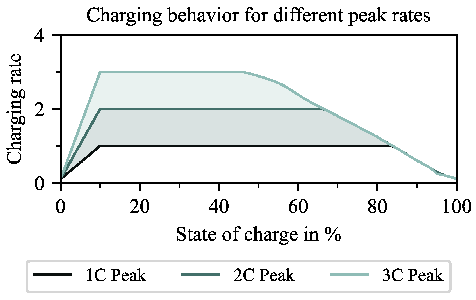
In addition to the environment constraints (Figure 3b), vehicle parameters are used as inputs to the simulation framework. The analyzed scenario defines the starting battery state S O C 0 and the desired state S O C d e s t at the end of the tour. In addition to these conditions, the minimum and maximum possible battery states S O C m i n = 0.15 and S O C m a x = 1 , as well as the maximum possible battery C-rate of 3 h−1, are selected for this work. This corresponds with common values for the usable energy content of automotive battery systems. The charging capability of the vehicle is nonlinear, with a plateau of 3C between S O C   0.1 and 0.5 and the subsequent constant-voltage phase, as depicted in Figure A2. The actual charging speed is thus limited by the nonlinear charging capability of the vehicle and the power of the charger, which are constant throughout a scenario.
The global optimization for determining the optimal charging strategy ensures that the desired state of charge (SOC) is maintained on arrival. However, suppose the scenario requires that the starting SOC and the SOC on arrival are identical, and the charging network does not provide a point of interest (POI) along a route due to insufficient density. In that case, this condition cannot be met. Therefore, we formulated this condition as a soft constraint to consider such routes. For this purpose, the charging time required at the destination to reach the prescribed SOC is added to the total time t o p as a penalty. A charging power of P d e s t = 350 k W is assumed for this recharging, so the additional time t a d d is calculated based on the truck’s battery capacity C b a t , as follows.
t a d d = max ( 0 , S O C d e s t S O C e n d ) · C b a t / P d e s t
Each simulated route returns a set of summarizing values of the simulated trip, comparable to a trip logbook. Total time, energy consumption, and SOC constraint violations are recorded, as well as relevant parameters regarding breaks that took place during the trip. Each break is described by the ID of the charging site, the amount of energy charged, the arrival time, and the rest time at the site. It should be noted that, in some cases, breaks without charging are required to fulfill the mandatory rest periods. In other cases, both processes take place simultaneously.
As a single simulation takes, on average, 27.6 s to run on a single thread of an Intel Xeon Silver 4214R, so the sequential computation of 160,400 routes for only one scenario is prohibitively expensive. This conflict is resolved by massive parallelization across 19 heterogeneous virtual machines with up to 20 threads each. A full simulation of a scenario takes approximately 6 h .

3.4. Scaling

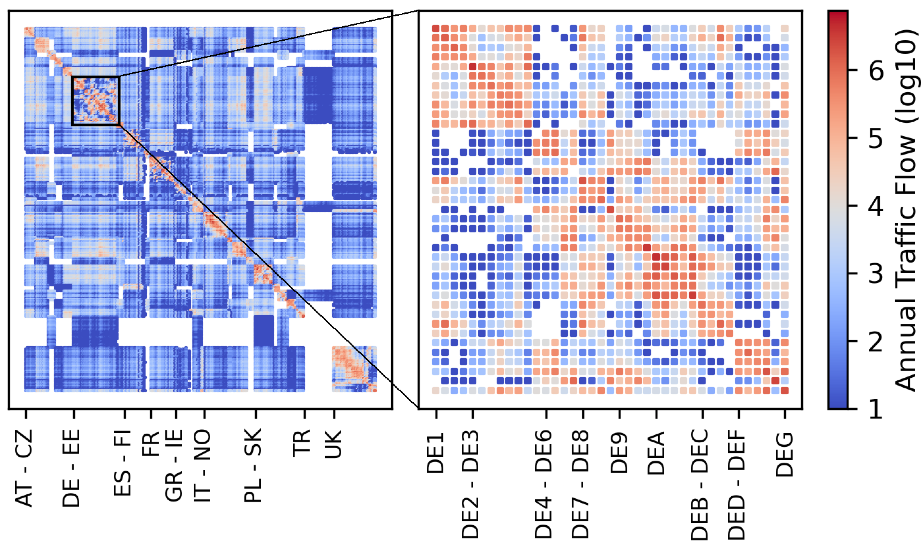
In order to incorporate the actual traffic flows, freight flow data from 2019, aggregated according to [25], are utilized. The dataset describes the OD matrix of traffic flows in trucks for European NUTS-3 regions and is visualized in Figure 4. It can be observed that the most frequented relations occur within a respective country (near the main diagonal). Some countries, like Cyprus, Finland, and Türkiye, are only loosely connected to the other European regions via road transport. Within Germany, all regions are relatively strongly interconnected. Particular clusters can be found in DE1 and DE2 (Southern Germany) and from DE9 to DEC (economic centers along the Rhine, Ruhr, and into Lower Saxony). In this study, only relations starting and ending in Germany are considered. This reduces computational effort, enables more scenarios to be compared, and is sufficient to build up the methodology. It can be observed that the German matrix is densely populated with traffic flows, which are roughly symmetric, reflecting the decentralized economic structure of the country. Domestic traffic accounts for approximately 85% of the mass of transported goods in Germany [26], with foreign traffic having higher market shares in long-haul transport.
The results of single-simulation runs are thus scaled according to the respective traffic flow between its origin and destination NUTS-3 regions. The breakdown of a single truck due to low SOC is weighted multiple times according to the corresponding traffic flow. The charging process is proportionally scaled in terms of kilowatt-hours (kWh). Finally, an electrification share s B E T and an annualization factor of 1 286.3 adjust the annual values of the underlying data to the level of an average weekday (Monday–Friday). The factor is calculated from averaged hourly traffic count data from 2108 stations along the German motorways from 2020, available on [32]. On an average weekday, 1 286.3 of the annual truck traffic was registered at the counting stations; on weekend days, on average, only 1 1223.5 of the annual traffic passed the stations.

3.5. Aggregation

This section explains the process of aggregating the 160,400 routes between the 401 NUTS-3 regions per scenario to meaningful performance indicators. Depending on vehicle parameters and the charging network, each simulated vehicle can either succeed and reach its destination or violate the lower SOC boundary, in which case the route would be infeasible to drive. Thus, each simulated route contributes either a time loss (which may be zero) or a number of vehicles that could not reach the destination in the total scenario results. The two effects shall be decoupled and evaluated separately: for the evaluation of time loss, only routes that were completed successfully in all comparable scenarios are considered. The cumulative excess time divided by the cumulative driving and mandatory rest time yields the relative time loss. The sum of the traffic flow that is assigned to routes where the lower SOC constraint was violated, compared to the total simulated traffic flow, yields the share of infeasible traffic flow. To which category a route belongs may vary between scenarios: A scenario with a higher payload and increased consumption may lead to a vehicle on a certain route not making it to the next charging site. On another route with higher charging site density, increased consumption may only increase the charging time and may not render completing the route infeasible.
The strategy BETOS calculates for the trucks is also evaluated: the number of stops per route, weighted according to the traffic flow on the route and by taking non-charging stops into account, provides insights about the strategy that is chosen. Another quantity of interest is the dwelling time at a rest location: to this end, the rest times are sorted into bins with the boundaries 0.4 h, 0.6 h, 0.8 h, and 1.2 h. Each stop is counted according to the traffic flow on the route and summed up to the rest events by duration.
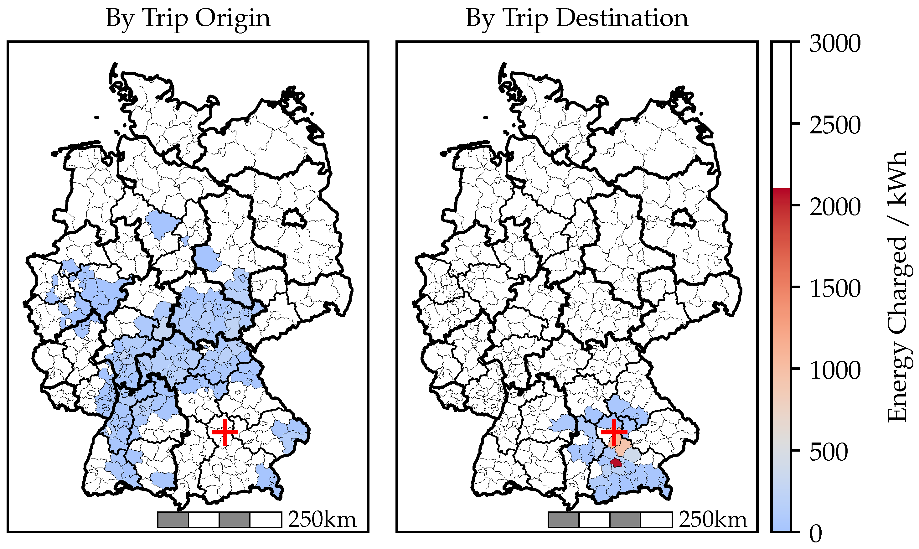
By rearranging the trips according to the charging points used, network-level quantities can be computed. As each charger is characterized by a unique ID, the charging processes can be traced back to the location where the charging took place. An example is provided in Figure 5. The charging processes at a site in southern Germany in an exemplary scenario are caused by trips originating in central, western, and southwestern Germany, with the origins widely distributed. The destinations are strongly concentrated within the Munich Metropolitan Area, with Munich being responsible for 30% of the energy charged.

4. Results

Multiple scenarios are simulated, representing reference scenarios as well as parameter variations of them. Infrastructure, strategy and vehicle parameters are varied; a detailed overview of all parameters is provided in Table A2.
The two charging networks, WMN and CMN, are simulated in reference cases where all trips start and end with a battery SOC of 50%. This setup ensures that trucks meet their energy needs en route, allowing for continuous long-haul transport without dependence on private charging infrastructure.
Each scenario varies a single parameter from the base cases. Changes in battery capacity of ±100 k W h are explored in different scenarios. The impact of a high 24 t payload versus an average 13.6   t payload is examined in other specific scenarios. Charging power limitations are assessed in further scenarios, considering the announced first-generation MCS chargers at 700 k W and a proposed increase to 1.5   M W , meeting the limits of 3C-capable battery cells at 500 k W h .
The study also investigates the effect of unavailable charging stations, a real-world issue caused by technical problems, communication network issues, or construction work. A 95% availability rate for car charging infrastructure is considered based on German data. Advanced scenarios simulate a 5% station outage, while others explore the effects of up to a 50% outage rate. We aim to further understand optimization potentials within the network under these varying conditions.

4.1. Network Performance

The system performance of the simulation scenarios without charging site outages is visualized in Figure 6. It should be noted that only routes of at least 240 k m (equivalent to 3 h of motorway driving) are included in the visualization to focus on long-haul transport. The method of aggregation is described in detail in Section 3.5. Globally, it can be observed that the network coverage in all scenarios is excellent, as more than 98% of the simulated routes are feasible without violation of the SOC constraint of 15%. The order of magnitude is in line with the findings by Menter et al. [26] (p. 15) of 0.3%. The time loss due to charging varies between 5.5% and 8.8%.
Among scenarios of a similar base network, an increase in charging power has the greatest impact on time loss and can cut time loss by about one fifth. Yet there is no impact on the share of infeasible routes, as gaps in the network remain unchanged, and insufficient traction energy can thus not be compensated. The effect of an increased battery capacity in the vehicle manifests as a marginally lower time loss combined with a lower infeasibility share. In contrast, lowered battery capacity and lowered charging power below the baseline of 500 k W h or 1 M W , respectively, show significant detrimental effects. This can be traced back to shorter driving legs and more necessary charging stops.
In the baseline scenario, all trucks carry 13.6   t of payload, far below their carrying capacity. It can be observed that the increased fuel consumption at a payload of 24 t renders some routes infeasible in wide-meshed networks. In contrast, the excess consumption can be remedied by refueling using the extra charging stations in CMNs. On both networks, logistics operators face an additional time loss of approximately 1.3%.
Comparatively, close-meshed networks perform strictly better in all corresponding scenarios: The increased number of charging stations offers better coverage and better synchronization of charging time with mandatory rest time. Also, a higher robustness to sub-optimal system parameters can be observed. This leads to the hypothesis that a network of higher density can also better compensate for site outages. Consequently, the specific system robustness to outages will be examined in detail in the following section.

4.2. Network Resilience

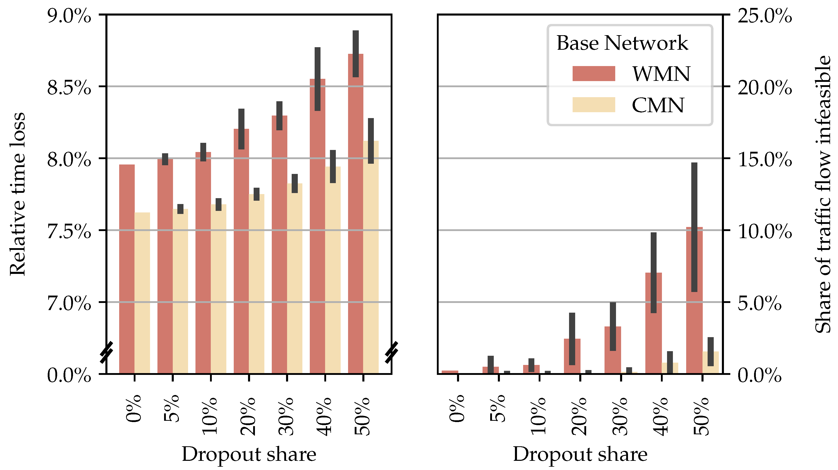
Figure 7 depicts the results of simulation runs with increasing random charger outages. The time loss is visualized to the left, whereas the right plot describes the effect on route infeasibility. Error bars in the plots indicate the standard deviation across multiple random draft scenarios, providing a measure of variability in the simulation outcomes.
The first key finding is the monotonic increase in time loss across derivatives from both base networks as outage levels increased. This is plausible because, by removing options from the agents, less preferable sites have to be selected. Bad synchronization with mandatory rest time and charging to higher SOC levels associated with slower charging are the main mechanisms of this time loss. Notably, the speed in the WMN without outages is on par with that in the close-meshed network at a 50% outage level. At the same time, both configurations have comparable numbers of charging sites and thus network density. This, again, demonstrates the correlation between network density and time loss.
In real-world availability scenarios, represented by a 5% outage, the performance loss was marginal but measurable, indicating that both networks are robust to minor disruptions. Moreover, the small standard deviation indicates a certain degree of redundancy in the system. Generally speaking, the influence on time loss in low-to-mid outage level scenarios was smaller than in the system parameter variations of Figure 6. This can be traced back to the fact that the effective network density of the configurations is higher than their nominal value: the base networks are designed to reflect the alternative fuel infrastructure regulation (AFIR) guidelines of 50 km/100 km distance between charging sites [19]. But by counting sites along the simulated routes and weighting the observations by the traffic flow, it can be proved that average site distances of 34.53   k m and 59.77   k m , respectively, could be achieved. This is due to sites at intersections serving a larger part of the network than in hypothetical, purely linear configurations.
The analysis of traffic flow rendered infeasible reveals that close to zero breakdowns occur in CMNs, even at a 50% outage, displaying their high resilience towards outages. Derivatives of the WMN, however, translate the outage share into route infeasibility, starting at a 20% share. Nevertheless, networks at 60% availability of the original offer more than 90% coverage for long-haul transport. The calculated effective network density is measured at 103.86   k m for this configuration.
To conclude, both networks display certain degrees of resilience towards outages, with the CMN providing far larger margins for outages. An important factor in this resilience is the strategic adaptations of the trucks, which pre-plan their respective strategies in the simulation optimally, even under outage scenarios. The mechanism of adaption is further examined in the following section.

4.3. Strategy

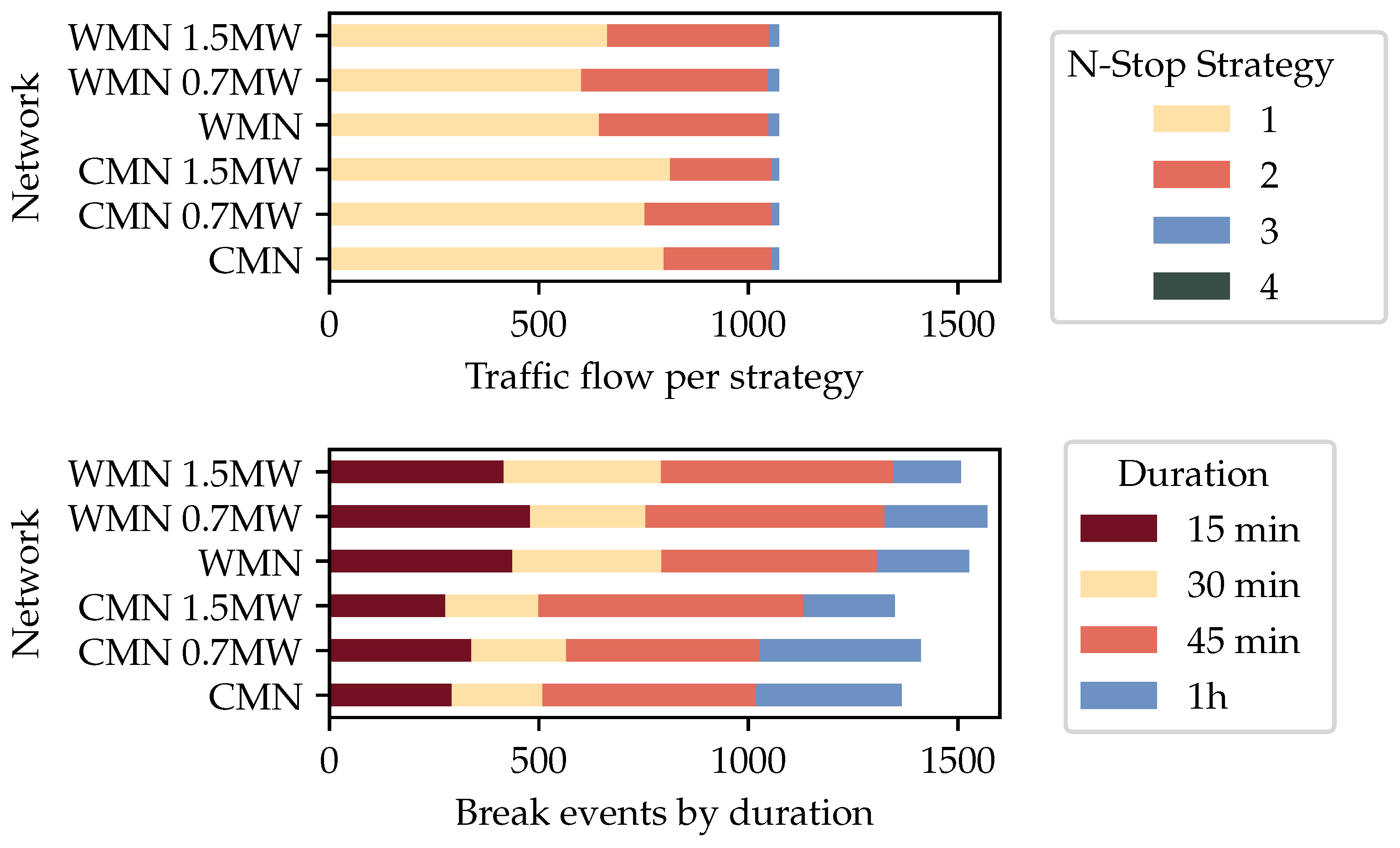
In the following analysis, only routes of at least 360 k m are included, corresponding to a driving time of at least 4.5 h at an average speed of 80 km h−1 on motorways. These routes definitely require a mandatory break of 45 min . The results are visualized in Figure 8. It should be noted that it is both legal and implemented in the BETOS to split the break into a 15 min break followed by a 30 min one.
In order to isolate the effect of network density on the strategy, again, the base case simulations of CMN and WMN are evaluated. Additionally, the influence of increasing and decreasing available power is assessed by the inclusion of the derived 700 k W and 1.5   M W networks.
Throughout our simulations, the same predefined routes are utilized, ensuring consistency across all scenarios. Consequently, the upper graph of Figure 8 exhibits consistent stacked lengths, while the second plot exhibits varying numbers of pauses due to different strategies.
It can be observed that with a greater abundance of charging infrastructure associated with the CMN, it becomes more likely for a perfectly fitting 45 min stop to be integrated into the strategy. This behavior can save the 6 min of plug time that is required on each break. Furthermore, a weak tendency towards longer breaks with higher power levels and, conversely, shorter breaks with lower power levels is visible. Notably, 45 min breaks account for only 36% to 46% of the rest events in all scenarios, calling into question the commonly modeled neglection of the allowed rest time split, as this not time optimal in most scenarios. [19,21,26]

5. Discussion

The method presented comprises a vehicle model, charging infrastructure, and a modeled operational strategy in a real application context. Within this article, we demonstrate the individual influence of all the components on the overall system performance. In order to evaluate the performance, two key performance indicators are evaluated: time loss and spatial coverage.
This article focuses on the time loss component due to charging and mandatory rest periods, while other components have to be addressed separately: The queuing of trucks at charging sites can significantly increase their travel time and has to be addressed through a separate time-forward simulation. The power demand at large sites can reach several megawatts; thus, the electric grid capacity may not be sufficient. A sufficient electric grid connection or, conversely, the limitations of power drawing may represent two solution approaches and may lead to markedly increased investment costs or increased time loss, respectively.
Our study highlights the suitability of both CMN and WMN networks [19] for long-haul transport within Germany due to their extensive spatial coverage of over 99.5%. However, wide-meshed networks have notable limitations: 1% of the routes can not be operated at a full payload, and a residual time loss of 7.2% on remaining long-haul routes remains, even without the need for queuing at the charging site. Improvements can be achieved by increasing the charging station power, resulting in shorter charging times and possibly more sessions at a site, which is particularly valuable when space is constrained. Conversely, the CMN network showcases comparably small performance benefits. From a system perspective, we thus conclude that increased charging power at a site is a better expansion strategy than densifying the network beyond the WMN.
Hecht et al. [17] analyzed time-optimal routes for private electric cars on German motorways, assuming a comparable rest time model as for trucks. Significant findings [17] (p. 18) are supported by this study: a residual time loss of 8% is in line with our estimation of about 7% (Figure 6). Yet differences in the scenario definition demonstrate the sensitivity to system parameters: when starting at only 50% SOC, the a median of 20% time is lost compared to conventional vehicles [17]. It should be noted that the ranges of private vehicles are about 25% lower and the average C-rates about twofold higher. The charging power is thus almost exclusively limited by the car, which is not the case in our simulation. The importance of multiple short stops, in comparison to fewer long charging sessions, is also highlighted by the short average charging times [17] (Figure 21).
By focusing on the public charging aspect of the system, it is possible to analyze the specific requirements of long-haul transport, especially in applications where private or public destination charging infrastructure at the origin and destination is not available. This aspect is especially important to highlight, as it is commonly modeled that trucks start their day fully charged and end with a depleted battery [17,20,26,27]. Our model shows that, in such cases on domestic routes, only 0.6% of the consumed traction energy on routes over 300 k m is drawn en route. With an average length of 343 k m among those routes and an electric range of approximately 400 k m , this is plausible. In related scenarios (100%/58% ensuring round-trip capability and 50%/50% ensuring infinite long-haul usage), our public charging share reaches 37% and 100%, respectively. Menter et al. [26] (Table 4) reach a public charging share of approximately 70%, which can partially be traced back to two modeling paradigms: the static charging strategy of charging up to 80%, whether needed or not for completing the driving task, increases charging demand, while foreign traffic puts more emphasis on long-haul routes. We conclude that quasi-stationary behavior should be achieved in future works so that public charging infrastructure is neither over- nor undersized, and temporal charging demand can be modeled more precisely.
The routing of trucks in this model reflects the current routes of conventional trucks: it optimizes driving time egoistically and statically under the neglection of dynamic constraints like queues at the charging hub. In this particular area, a routing engine that includes charging infrastructure parameters like power and density on different routes might further improve the speed of trucks. Queues at charging sites, describing dynamic components of the time loss, have been extensively studied in other research and will be considered in future iterations of the model. In the scope of this article, infrastructure parameters are assumed to be known at the moment of departure. This is a sound assumption for static information like the installed power and number of plugs at a site. For outage scenarios, an information system to communicate live availability would be required, however. Without this information, unknown site outages might result in significantly higher time losses or even the breakdown of vehicles. The increased travel time in outage scenarios was also highlighted by Hecht et al. [17], with approximately 2% to 7% excess time loss under varying outage scenarios, in line with our estimates of 0% to 10% on derivatives of the WMN.
Finally, the scope of the presented model is limited to Germany and intra-German traffic. Through the inclusion of European transit traffic, we expect that the focus will shift towards long-haul traffic in general, and spatially on the main routes of the TEN-T network in particular. The presented model offers these capabilities, as all data sources were picked and processed such that it is consistent throughout Europe.

6. Conclusions

This study advances the understanding of the interaction between battery electric trucks (BETs), their operational strategy, and fast charging infrastructure. Through simulation and evaluation, the research provides a detailed analysis of the performance and resilience of proposed charging networks and possible derivatives.
A crucial finding is that all analyzed networks are sufficient in terms of coverage to support electric trucks in Germany, even with reasonable security margins. Yet a time loss of 5.5% to 8.9% remains and can be mitigated most effectively through increased charging power. In contrast, the potential of improved battery capacity is found to be lower. This study also examines how outages in the network induce an adapted strategy. By shifting towards multiple shorter charging stops, time loss can be limited to an additional 0.12% at a 10% outage rate on a coarse charging network. The network density can be reduced by another 30% while still maintaining a coverage of over 90%.
While the case study was executed on two existing networks and their derivatives in Germany, the methodology and insights offer a widely applicable method of assessing the quality of service of charging networks throughout Europe.
In summary, this research significantly contributes to charging infrastructure planning, offering practical guidance for the development of efficient and resilient charging networks. However, its findings are equally relevant to regulatory bodies and logistics operators responsible for determining the efficiency of the system of electric goods transport.

Author Contributions

Conceptualization, G.B., M.Z., J.S. and M.L.; methodology, G.B. and M.Z.; software, G.B. and M.Z.; validation, G.B. and J.S.; data curation, G.B.; writing—original draft preparation, G.B., J.S. and M.Z.; writing—review and editing, G.B., J.S. and M.L.; visualization, G.B. and M.Z.; supervision, M.L.; project administration, G.B., M.Z. and J.S.; funding acquisition, M.L. All authors have read and agreed to the published version of the manuscript.

Funding

The research of M.Z., J.S. and G.B. was funded by the Federal Ministry for Economic Affairs and Climate Protection within the research project NEFTON (FKZ: 01MV21004A).

Data Availability Statement

The raw data supporting the conclusions of this article will be made available by the authors on request.

Conflicts of Interest

The authors declare no conflicts of interest.

Abbreviations

The following abbreviations are used in this manuscript:
AFIRAlternative Fuel Infrastructure Regulation
BETBattery Electric Truck
BETOSBattery Electric Truck Operational Strategy
CMNClose-meshed Network
CPCharging points
GISGeographic Information Systems
MCSMegawatt Charging System
NUTSNomenclature of Territorial Units for Statistics
OSMOpen Street Maps
POIPoints of Interest
SOCState of Charge
TEN-TTrans-European Transport Network
WMNWide-meshed Network

Appendix A. Details of the Presented Model

Appendix A.1. Charging Network

Figure A1. Overview of the simulated charging networks adapted from Speth et al. [19]. Red: CMN. Blue: WMN.
Wevj 15 00032 g0a1
Figure A2. Charging curves of different cell models as in [31]; this article exclusively simulates a 3C peak C-rate.
Wevj 15 00032 g0a2

Appendix A.2. Highway Network

Table A1. OSM street types and respective default speed limits used, in accordance with German laws. Speed limits are overridden if a specific speed limit for trucks (key: “maxspeed:hgv”) is provided.
Values of “Highway” KeyMax SpeedSpecific Edge Cost in h km 1
motorway, trunk80 km h−1 0.01250
primary, secondary, tertiary60 km h−1 0.01667
motorway_link, trunk_link, primary_link, secondary_link, tertiary_link motorway_junction30 km h−1 0.03333
road50 km h−1 0.02000

Appendix A.3. Simulation Parameters

Table A2. Overview of simulation parameters and variations. Default parameter value marked with an asterisk.
ParameterValues
Base network WMN *
CMN *
Battery capacity400  k W h
500  k W h *
600  k W h
Charging power (max.)700  k W
1000  k W *
1500  k W
SOC at start/end100%/50%
100%/15%
50%/50% *
Payload  13.6   t  *
24 t
Outage Random 50%
Random 40%
Random 30%
Random 20%
Random 10%
Random 5%
0% *

References

  1. Razmjoo, A.; Ghazanfari, A.; Jahangiri, M.; Franklin, E.; Denai, M.; Marzband, M.; Astiaso Garcia, D.; Maheri, A. A Comprehensive Study on the Expansion of Electric Vehicles in Europe. Appl. Sci. 2022, 12, 11656. [Google Scholar] [CrossRef]
  2. European Automobile Manufacturers’ Association (ACEA). New Medium and Heavy Commercial Vehicle Registrations by Fuel Type, European Union. Available online: https://www.acea.auto/files/ACEA_Trucks_by_fuel_type_full-year-2022.pdf (accessed on 8 March 2023).
  3. Wolff, S.P. Eco-Efficiency Assessment of Zero-Emission Heavy-Duty Vehicle Concepts. Ph.D. Thesis, Technische Universität München, Munich, Germany, 2023. [Google Scholar]
  4. Daimler Truck AG. Der Man Etgx Elektrifiziert Den Fernverkehr. Available online: https://www.man.eu/de/de/lkw/alle-modelle/der-man-tgx/der-man-etgx/uebersicht.html (accessed on 27 November 2023).
  5. MAN Truck & Bus SE. Der neue eActros|600 Charged to Change. Available online: https://eactros600.mercedes-benz-trucks.com/de/de/eactros-600/showroom.html (accessed on 27 November 2023).
  6. Sugihara, C.; Hardman, S.; Kurani, K. Social, technological, and economic barriers to heavy-duty truck electrification. Res. Transp. Bus. Manag. 2023, 51, 101064. [Google Scholar] [CrossRef]
  7. Aral Aktiengesellschaft. Dekarbonisierung des Schwerlastverkehrs: Aral Eröffnet Europas Ersten Ladekorridor für Elektrische Lkw. Available online: https://www.aral.de/de/global/retail/presse/pressemeldungen/pm-2023-aral-eroeffnet-europas-ersten-ladekorridor-fuer-elektrische-lkw.html (accessed on 27 November 2023).
  8. Commercial Vehicle Charging Europe B.V. Milence and Port of Antwerp-Bruges Reach an Agreement to Develop a 30-Bay Charging Hub for Heavy-Duty Vehicles. Available online: https://milence.com/press-release/milence-and-port-of-antwerp-bruges-reach-an-agreement-to-develop-a-30-bay-charging-hub-for-heavy-duty-vehicles/ (accessed on 22 November 2023).
  9. Council of the EU and the European Council. Fit for 55: Towards More Sustainable Transport—Consilium. Available online: https://www.consilium.europa.eu/en/infographics/fit-for-55-afir-alternative-fuels-infrastructure-regulation/ (accessed on 14 August 2023).
  10. NOW GmbH—National Centre for Charging Infrastructure. Einfach Laden an Rastanlagen | Auslegung des Netzanschlusses für E-Lkw-Lade-Hubs. Available online: https://nationale-leitstelle.de/wp-content/uploads/2022/09/Leitstelle_LKW-Netzstudie.pdf (accessed on 27 November 2023).
  11. Zähringer, M.; Wolff, S.; Schneider, J.; Balke, G.; Lienkamp, M. Time vs. Capacity—The Potential of Optimal Charging Stop Strategies for Battery Electric Trucks. Energies 2022, 15, 7137. [Google Scholar] [CrossRef]
  12. PostGIS Project Steering Committee and Others: PostGIS, Spatial and Geographic Objects for postgreSQL. Software Version 3.3.2. Available online: https://postgis.net (accessed on 7 April 2023).
  13. pgRouting Project—Open Source Routing Library. Software Version 3.5.0. Available online: https://pgrouting.org/ (accessed on 14 August 2023).
  14. Deb, S.; Tammi, K.; Kalita, K.; Mahanta, P. Review of recent trends in charging infrastructure planning for electric vehicles. WIREs Energy Environ. 2018, 7, e306. [Google Scholar] [CrossRef]
  15. Metais, M.; Jouini, O.; Perez, Y.; Berrada, J.; Suomalainen, E. Too much or not enough? Planning electric vehicle charging infrastructure: A review of modeling options. Renew. Sustain. Energy Rev. 2022, 153, 111719. [Google Scholar] [CrossRef]
  16. Al-Hanahi, B.; Ahmad, I.; Habibi, D.; Masoum, M.A.S. Charging Infrastructure for Commercial Electric Vehicles: Challenges and Future Works. IEEE Access 2021, 9, 121476–121492. [Google Scholar] [CrossRef]
  17. Hecht, C.; Victor, K.; Zurmühlen, S.; Sauer, D.U. Electric vehicle route planning using real-world charging infrastructure in Germany. eTransportation 2021, 10, 100143. [Google Scholar] [CrossRef]
  18. Speth, D.; Sauter, V.; Plötz, P. Where to Charge Electric Trucks in Europe—Modelling a Charging Infrastructure Network. World Electr. Veh. J. 2022, 13, 162. [Google Scholar] [CrossRef]
  19. Speth, D.; Plötz, P.; Funke, S.; Vallarella, E. Public fast charging infrastructure for battery electric trucks—A model-based network for Germany. Environ. Res. Infrastruct. Sustain. 2022, 2, 025004. [Google Scholar] [CrossRef]
  20. Borlaug, B.; Moniot, M.; Birky, A.; Alexander, M.; Muratori, M. Charging needs for electric semi-trailer trucks. Renew. Sustain. Energy Transit. 2022, 2, 100038. [Google Scholar] [CrossRef]
  21. Shoman, W.; Yeh, S.; Sprei, F.; Plötz, P.; Speth, D. Battery electric long-haul trucks in Europe: Public charging, energy, and power requirements. Transp. Res. Part D Transp. Environ. 2023, 121, 103825. [Google Scholar] [CrossRef]
  22. Hurtado-Beltran, A.; Rilett, L.R.; Nam, Y. Driving Coverage of Charging Stations for Battery Electric Trucks Located at Truck Stop Facilities. Transp. Res. Rec. 2021, 2675, 850–866. [Google Scholar] [CrossRef]
  23. Danese, A.; Garau, M.; Sumper, A.; Torsæter, B.N. Electrical Infrastructure Design Methodology of Dynamic and Static Charging for Heavy and Light Duty Electric Vehicles. Energies 2021, 14, 3362. [Google Scholar] [CrossRef]
  24. Çabukoglu, E.; Georges, G.; Küng, L.; Pareschi, G.; Boulouchos, K. Battery electric propulsion: An option for heavy-duty vehicles? Results from a Swiss case-study. Transp. Res. Part Emerg. Technol. 2018, 88, 107–123. [Google Scholar] [CrossRef]
  25. Speth, D.; Sauter, V.; Plötz, P.; Signer, T. Synthetic European road freight transport flow data. Data Brief 2022, 40, 107786. [Google Scholar] [CrossRef] [PubMed]
  26. Menter, J.; Fay, T.A.; Grahle, A.; Göhlich, D. Long-Distance Electric Truck Traffic: Analysis, Modeling and Designing a Demand-Oriented Charging Network for Germany. World Electr. Veh. J. 2023, 14, 205. [Google Scholar] [CrossRef]
  27. Schneider, J.; Teichert, O.; Zähringer, M.; Balke, G.; Lienkamp, M. The novel Megawatt Charging System standard: Impact on battery size and cell requirements for battery-electric long-haul trucks. eTransportation 2023, 17, 100253. [Google Scholar] [CrossRef]
  28. Balke, G.; Adenaw, L. Heavy commercial vehicles’ mobility: Dataset of trucks’ anonymized recorded driving and operation (DT-CARGO). Data Brief 2023, 48, 109246. [Google Scholar] [CrossRef] [PubMed]
  29. Asamer, J.; Reinthaler, M.; Ruthmair, M.; Straub, M.; Puchinger, J. Optimizing charging station locations for urban taxi providers. Transp. Res. Part D Policy Pract. 2016, 85, 233–246. [Google Scholar] [CrossRef]
  30. Moeller, C. Osm2po-OpenStreetMap Converter and Routing Engine for Java. Software Version 5.5.6. Pinneberg, Germany. Available online: https://osm2po.de/ (accessed on 14 August 2023).
  31. Zähringer, M.; Wolff, S.; Schneider, J.; Balke, G.; Lienkamp, M. Essential for battery electric long-haul trucks: An optimal dynamic charging strategy. eTransportation 2024. under review. [Google Scholar]
  32. Bundesanstalt für Straßenwesen BaSt. Automatische Dauerzählstellen auf Autobahnen und Bundesstraßen. Available online: https://www.bast.de/DE/Verkehrstechnik/Fachthemen/v2-verkehrszaehlung/Verkehrszaehlung.html (accessed on 2 November 2023).
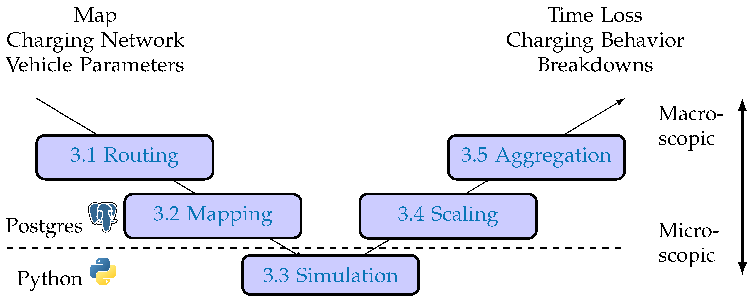
Figure 1. Visual abstract of the method presented. The data processing and geographical operations were carried out on a PostgreSQL 15 cluster using the PostGIS [12] and pgRouting [13] extensions. Simulation tasks were fetched by 19 different hosts and computed in parallel in Python, after which results were sent back to the PostgreSQL cluster for storage, evaluation, and aggregation.
Wevj 15 00032 g001
Figure 2. All time-minimizing routes leading to to Nomenclature of Territorial Units for Statistics (NUTS)-3 region DE211, the City of Munich. The speed limit is mostly 60 or 80 km h−1, apart from links and junctions. Most traffic flows are captured by motorways after a few kilometers on regular highways. Attribution: Map tiles by Stamen Design, CC BY 3.0—Map data © OpenStreetMap contributors.
Wevj 15 00032 g002
Figure 3. Schematic overview of the mapping process. (a) Chargers are projected onto the route, using the shortest distance method. Chargers deviating from the route by more than 10 k m are discarded. (b) Route sample: speed limits along the Gera–Plön route. Available chargers are displayed as green markers. Motorway changes are visible as short segments with 30 km h−1 speed limits.
Wevj 15 00032 g003
Figure 4. OD matrix of traffic flows in Europe (left) and Germany (right) per NUTS-2 region. Own visualization based on data from [25]. Colors indicate the intensity of traffic flow; domestic traffic for each country can be found near the main diagonal. Legend is X/Y symmetrical. Left: European countries (NUTS-0). Right: German regions (NUTS-2). The regions are provided in the 2006 revision of NUTS regions and are thus mapped to the closest NUTS-3 region of 2021 for this article.
Wevj 15 00032 g004
Figure 5. Origin and destination of trucks responsible for charging events at site ID 2102 in an exemplary scenario. The site is marked by a red cross and is located just south of Ingolstadt (Bavaria). The color scale indicates the energy aggregated by the NUTS-3 region of destination/origin.
Wevj 15 00032 g005
Figure 6. System performance of unilaterally time-optimized trucks operating within proposed charging networks. Each shape represents a single parameter variation of vehicle or infrastructure. The color indicates the network density of the base network (CMN vs. WMN). The KPI calculation is explained in detail in Section 3.5.
Wevj 15 00032 g006
Figure 7. Network-level system performance of networks derived from CMN and WMN through random site removal. At higher dropout rates, the time loss increases as more unfavorable charging stops have to be factored in. Also, certain routes become infeasible to drive due to the amount of energy left. The KPI calculation is explained in detail in Section 3.5.
Wevj 15 00032 g007
Figure 8. Evaluation of the strategies selected in varying infrastructure scenarios on long-haul routes of at least 360  k m . (Upper) plot: number of scheduled stops in a trip. 4 stops are only required in edge cases. (Lower) plot: duration of the stops, binned at 0.2   h , 0.6   h , 0.8   h and 1.2   h . No stops above these limits were scheduled.
Wevj 15 00032 g008
Disclaimer/Publisher’s Note: The statements, opinions and data contained in all publications are solely those of the individual author(s) and contributor(s) and not of MDPI and/or the editor(s). MDPI and/or the editor(s) disclaim responsibility for any injury to people or property resulting from any ideas, methods, instructions or products referred to in the content.