Article

Design Optimization of a New Hybrid Excitation Drive Motor for New Energy Vehicles

1
School of Transportation and Vehicle Engineering, Shandong University of Technology, Zibo 255049, China
2
Weifang No. 1 Motor Factory Co., Ltd., Weifang 262127, China
3
Shandong Wuzheng Group Co., Ltd., Rizhao 262306, China
*
Author to whom correspondence should be addressed.
World Electr. Veh. J. 2023, 14(1), 4; https://doi.org/10.3390/wevj14010004
Submission received: 21 November 2022 / Revised: 20 December 2022 / Accepted: 20 December 2022 / Published: 23 December 2022

Abstract

:
In this paper, a new hybrid excitation drive motor (HEDM) was proposed to solve the problem of an uncontrollable magnetic field of a permanent magnet motor. The rotor part of the motor was composed of a combined magnetic pole permanent magnet rotor and a brushless electric claw rotor, in which the combined magnetic pole permanent magnet rotor has a parallel magnetic circuit structure. According to the characteristics of the parallel rotor structure, the equivalent magnetic circuit model was established, and the no-load leakage flux coefficient of the claw pole rotor was calculated. The Taguchi method was used for objective optimization of the permanent magnet rotor structure. The distortion rate of no-load back electromotive force (EMF) was taken as the first optimization goal; the cogging torque and the average torque were taken as the second optimization goal; and the torque fluctuation coefficient was a constraint condition. The optimal parameter matching under the mixed horizontal matrix was obtained. The parameters of the claw pole were optimized by using the method of uniform variables, and the dimension parameters of the motor were obtained. Finite element analysis and prototype tests were carried out for the optimized motor structure. The rationality and feasibility of the new HEDM as a vehicle motor were verified, which provided a possibility for the application of the new energy vehicle drive motor field.

1. Introduction

At present, the widely studied drive system for new energy vehicles requires a small volume, high efficiency, large torque, and a wide range of speed regulation. The permanent magnet motor has become a research hotspot. With the rapid development and application of the rare earth permanent magnet material Nd-Fe-B, the rare earth permanent magnet motor with good performance has been widely used in high-performance electric vehicles [1]. However, due to the inherent properties of permanent magnet materials, the air gap magnetic field of a permanent magnet motor remains constant and cannot be adjusted, which limits its use in a wide speed control drive system. The cost of motor speed control through the control system is high, and the speed range is small [2]. Therefore, the design of a driving motor with adjustable speed and high output efficiency becomes the focus of our research.
The hybrid magnetic circuit drive motor effectively combines the permanent magnetic (PM) potential source and the electric excitation potential source in the structure, realizing the direct adjustment and control of the air gap magnetic field. It not only has the advantages of high-power density and high efficiency of the permanent magnet motor but also has the characteristics of a smooth and adjustable air gap magnetic field of the electric excitation motor, which meets the requirements of a high-performance electric vehicle drive system [3,4,5]. The research on it has important theoretical significance and engineering application value.
Different scholars have conducted a lot of research on hybrid magnetic drive motors. Reference [6] proposed a novel hybrid excitation wound synchronous motor. Compared with other types of synchronous motors, the motor had a simple structure and high torque. However, the torque ripple was too large, and the requirements for the inverter and control strategy were higher, which led to the complexity of the motor control system. Reference [7] proposed a new type of variable magnetic field ring-wound permanent magnet motor. The motor rotor consisted of a surface-mounted PM and a salient pole iron core, and the excitation winding was wound on both sides of the axial end of the salient pole rotor iron core. The PM circuit of the motor was connected in parallel with the electric excitation circuit so that it had good magnetic adjustment ability. However, the surface-mounted magnet steel was limited by mechanical stress, the eddy current loss increased, and the efficiency decreased. Reference [8] proposed a new hybrid excitation motor with a magnetic barrier and magnetic bridge. The magnetic barrier was set at the bottom between the adjacent permanent magnets of the rotor part, a guiding magnetic bridge was added in the middle of the rotor, and the excitation windings were arranged on the stator. The motor had a high-power density, high efficiency, and a certain magnetic adjustment ability. However, only tangential permanent magnetic steel was selected for the motor, which led to a large magnetic leakage coefficient. Additionally, corresponding magnetic separation measures needed to be arranged. Reference [9] proposed a new type of synthetic slot dual permanent magnet drive motor. The motor was composed of internal and external double rotors and an H-shaped stator. The dual permanent magnet drive can achieve a high torque density and a good modulation effect. However, the magnetic flux leakage coefficient and manufacturing cost of the motor increased. Reference [10] proposed to use a genetic algorithm and finite element analysis to obtain more sinusoidal back EMF, but the establishment and solution analysis of an objective function by the genetic algorithm were more complicated, and it had limitations in objective optimization design. For the optimization method, domestic scholars proposed using the Taguchi method for objective optimization [11,12]. Moreover, the Taguchi method can realize the objectively optimal design of the motor. It can not only realize the rapid design of the motor but also have high design precision. It has been widely used in the design and development of drive motors [13,14]. It can reduce the number of tests and improve the efficiency of the experiment. However, the traditional Taguchi method has the same number of horizontal values for each optimization factor, so it is difficult to get the optimal solution [15].
To reduce the cogging torque and improve the output torque of the motor and make it have a good ability to adjust the magnetic field, a new hybrid excitation drive motor was proposed in this paper. The equivalent magnetic circuit model of the hybrid excitation drive motor was established, and the no-load flux leakage coefficient of the claw pole part of brushless excitation was analyzed. Two parallel rotors were optimized respectively, and the key parameters at the magnetic barrier of the combined magnetic pole permanent magnet rotor were selected as optimization variables, and an objective optimization scheme was proposed by using the Taguchi method. In the part of the brushless electric excitation claw pole rotor, the parameters affecting magnetic flux leakage were selected by using the calculated no-load magnetic flux leakage coefficient, and these parameters were optimized. It was verified by finite element simulation and a prototype experiment.

2. Structure and Magnetic Circuit Analysis of HEDM

A permanent magnet motor has high power density and high efficiency, but the permanent magnet magnetic field is not adjustable, and the control system is complicated. The electric excitation motor is easy to control, and the output torque can be controlled, but it has high excitation loss and low efficiency. This paper presents a three-phase hybrid excitation synchronous drive motor with a permanent magnet and electromagnetic combination that combines the characteristics of high efficiency and high-power density of a permanent magnet motor and the simple control of an electric excitation motor hereinafter referred as a hybrid excitation drive motor.

2.1. Motor Structure

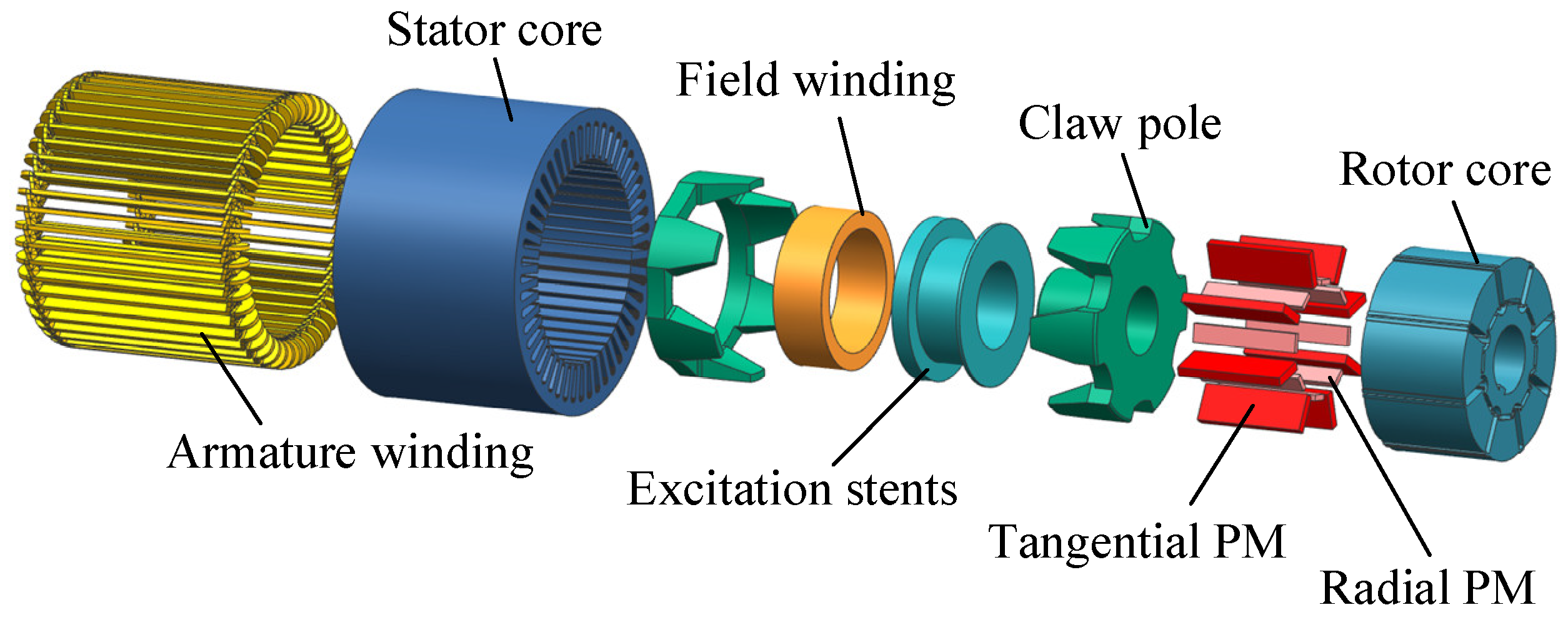
The HEDM for new energy vehicles is composed of a stator and a rotor. The rotor part is composed of a brushless electric excitation claw pole rotor and a combined magnetic pole permanent magnet rotor, which can not only retain the advantages of the high power of the PM field but also adjust the size of the magnetic field. The structure of the HEDM is shown in Figure 1. The main parameters of the motor are shown in Table 1.

2.2. Magnetic Circuit Analysis of HEDM

The hybrid excitation drive motor is a parallel magnetic potential source structure, and its main magnetic circuit is divided into two parts, which are the combined magnetic pole PM circuit and the brushless electric excitation magnetic circuit. The two magnetic circuits share a stator, and the two magnetic circuits are independent of each other. The synthetic magnetic circuit is a vector superimposed on the stator, and the size of the synthetic magnetic field is changed by changing the size and direction of the excitation current. The output torque of the hybrid excitation drive motor can be adjusted by changing the excitation current.

2.2.1. Magnetic Circuit Analysis of the Combined Magnetic Pole PM Rotor

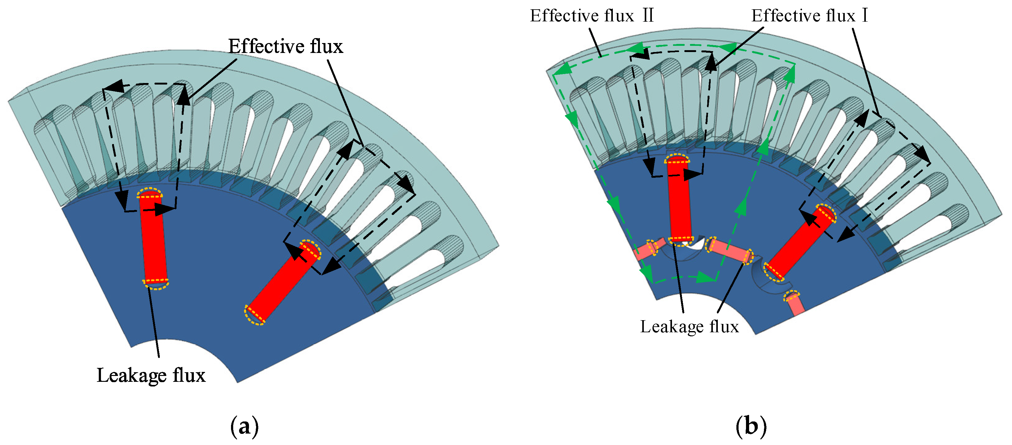
In this paper, the traditional single-radial PM steel structure is used as a comparison to analyze the magnetic circuit of the two motor structures. Figure 2 is a comparison diagram of magnetic flux paths. It can be seen that the effective magnetic flux of the traditional tangential structure is a single path, the magnetic field lines in the middle of the two adjacent radial permanent magnetic steels are sparse, and the air gap magnetic density waveform sag is seriously concave. The effective flux of the combined magnetic pole structure consists of two parallel paths. The addition of the auxiliary radial magnetic steel makes up the problem of the air gap magnetic density waveform depression.
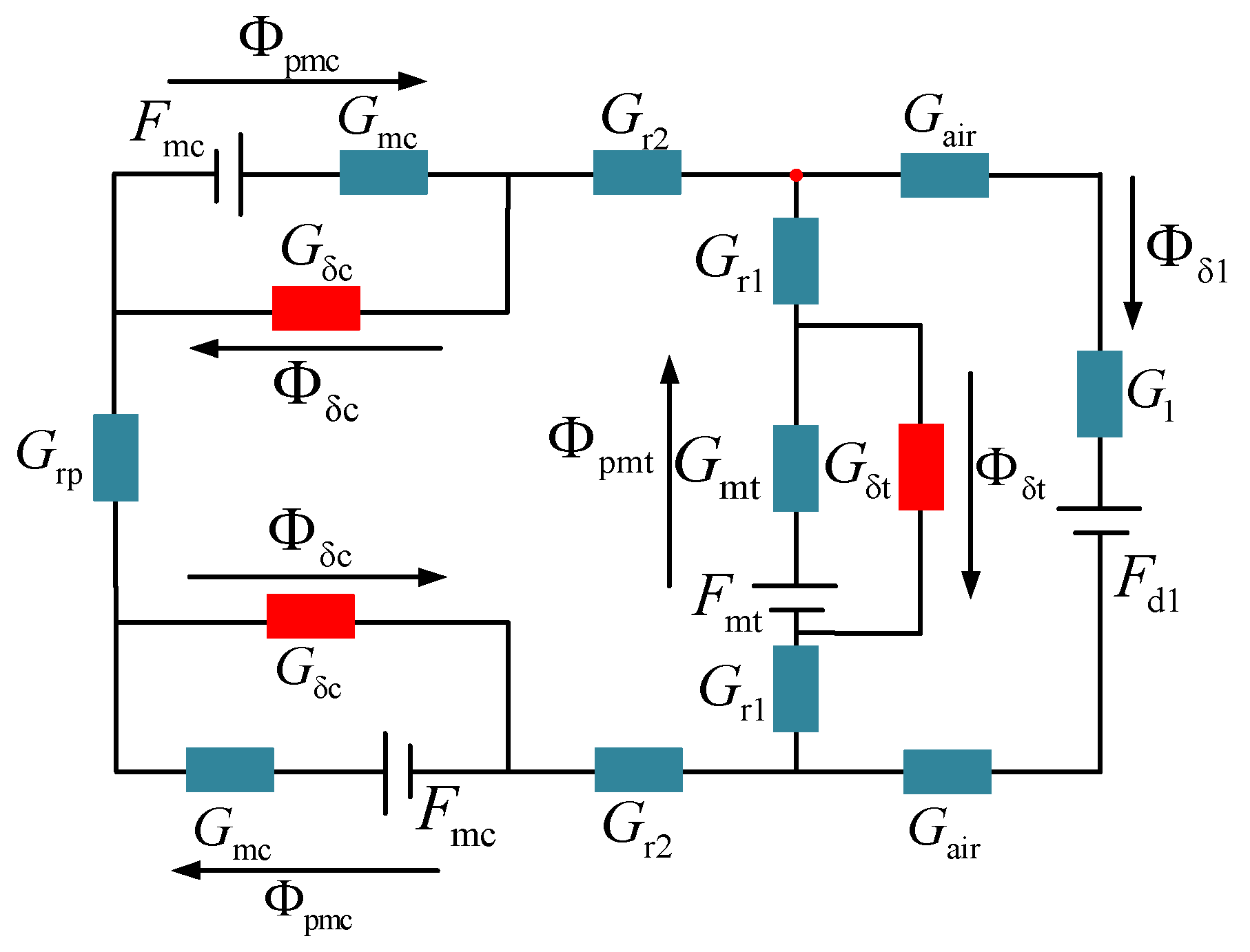
The main flux of the combined magnetic pole structure is provided by tangential permanent magnetic steel and an effective flux line. Figure 2 is the main magnetic circuit of PM steel: tangential permanent magnetic steel N pole→rotor core→air gap→stator core→air gap→rotor core→tangential permanent magnetic steel S pole. The radial permanent magnetic steel is placed between two tangential permanent magnetic steels, and its polarity is the same as that of the tangential permanent magnetic steel at the same pole. Partial magnetic leakage is prevented by the principle of repulsion at the same pole. Effective flux Ⅱ in Figure 2 is the magnetic circuit of the auxiliary magnetic steel: radial permanent magnetic steel N pole→rotor core→air gap→stator core→air gap→rotor core→radial permanent magnetic steel S pole. Figure 3 is the equivalent magnetic circuit model of the combined magnetic pole permanent magnet rotor based on the magnetic circuit analysis. The two magnetic circuits are connected in parallel, and the radial permanent magnet steel is used as the auxiliary magnetic pole, which brings more magnetic field capacity, improves the problem of air gap magnetic field depression caused by the tangential magnetic field, improves the magnetic gathering capacity, and further optimizes the sinusoidality of the air gap magnetic density waveform.
Where Fmt and Fmc is the magneto-motive force generated by tangential permanent magnet steel and radial permanent magnet steel, Gmt and Gmc is the equivalent internal magnetic conductivity of tangential permanent magnetic steel and radial permanent magnetic steel, G δ t is the flux leakage conductance at the outer and inner ends of tangential permanent magnet steel, G δ c is the magnetic flux leakage conductance at the left and right ends of radial permanent magnet steel, Gr1 and Gr2 is the magnetic conductivity of the rotor core of effective magnetic circuit Ⅰ and effective magnetic circuit Ⅱ, Grp is the magnetic conductivity of the rotor core between two adjacent radial permanent magnetic steels in effective magnetic circuit Ⅱ, Gair is the main air gap permeability, G1 is the magnetic conductivity of stator teeth and stator yoke of the combined magnetic pole permanent magnet motor, Fd1 is the magneto-motive force under the straight axis of the armature reaction under the no-load state of the motor, Φ pmt and Φ pmc is the magnetic flux generated by tangential permanent magnet steel and radial permanent magnet steel, Φ δ t and Φ δ c is the flux leakage generated by tangential and radial permanent magnetic steels, Φ δ 1 is the effective main flux of effective magnetic circuit Ⅰ and effective magnetic circuit Ⅱ.

2.2.2. Magnetic Circuit Analysis of the Claw Pole Rotor

The main magnetic flux path of the brushless electric excitation claw pole rotor is provided by the induced magnetic field generated by the input current of the wound coil, and the magnitude and direction of the excitation magnetic field are also different due to the different directions of the input current.
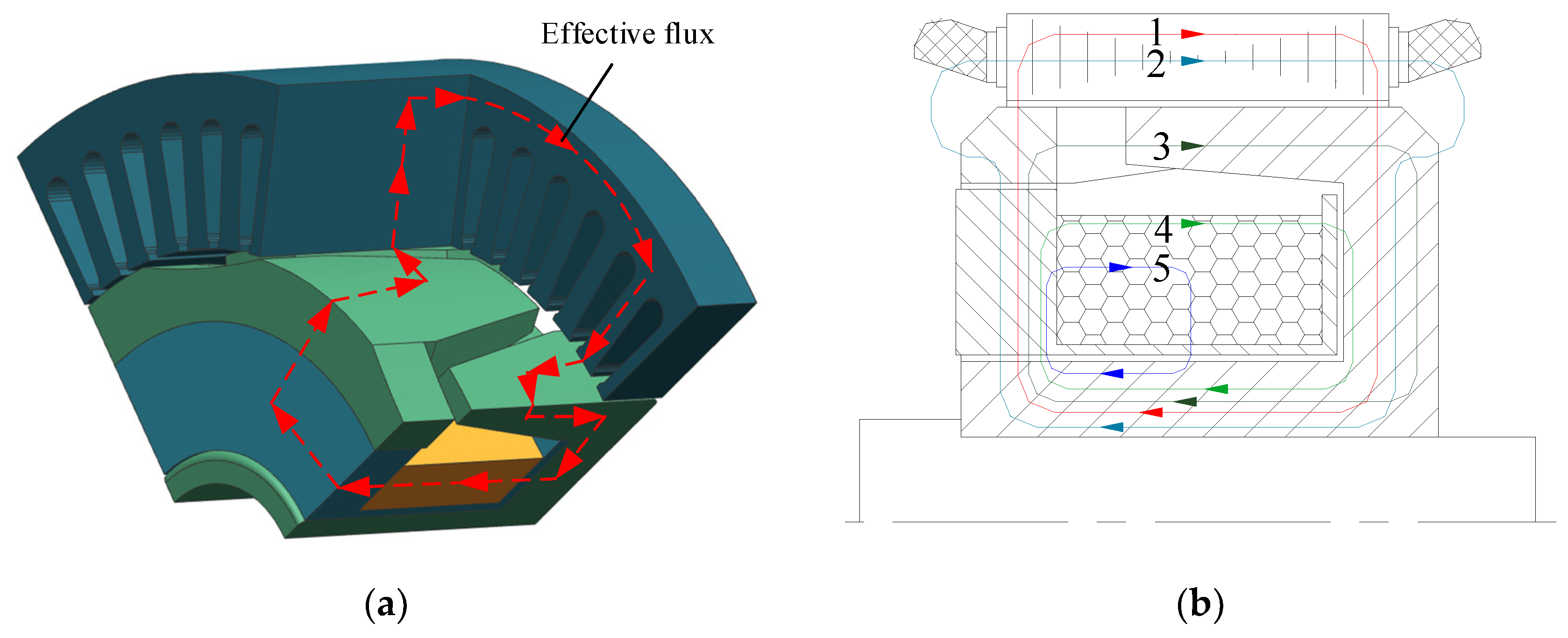
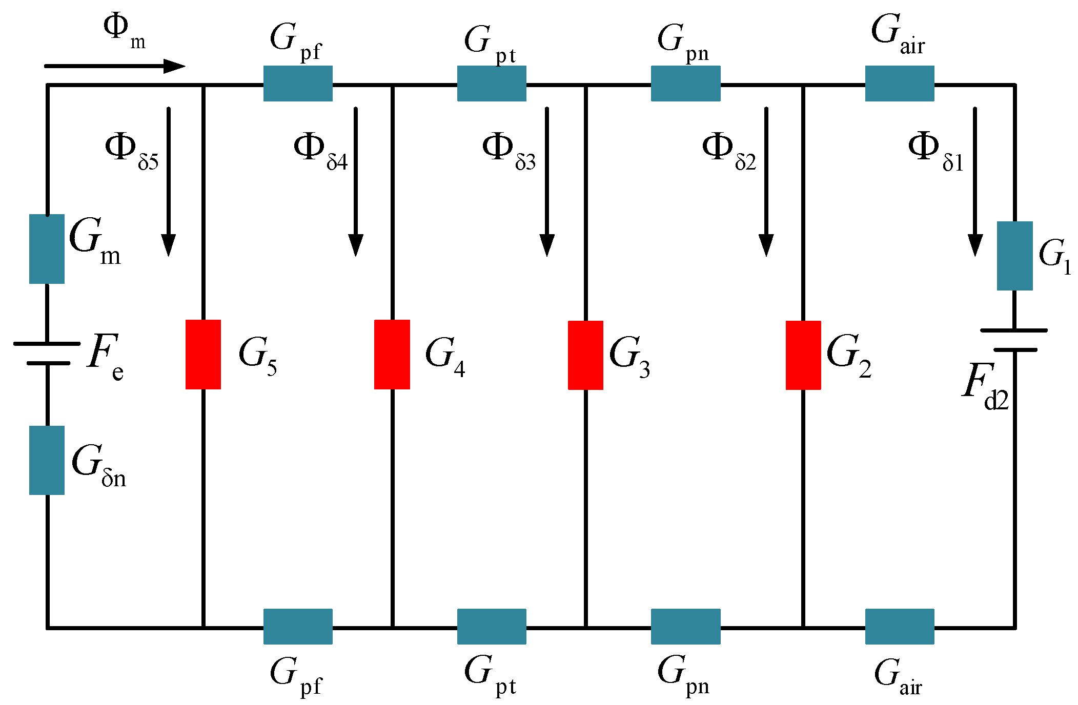
As shown in Figure 4, the forward electric excitation flux path is N-pole induced by the electric excitation coil→excitation bracket→claw pole→main air gap→stator tooth→ stator yoke→stator tooth→main air gap→claw pole root→flange→S pole induced by the electric excitation coil, forming a complete closed loop. In Figure 4b, the closing curve 1 is the claw pole main flux, while the other four curves are the claw pole leakage flux. The equivalent magnetic circuit diagram can be drawn from Figure 4b, as shown in Figure 5. Figure 5 is the equivalent magnetic circuit model of the brushless electric excitation claw pole rotor obtained according to the analysis of the magnetic circuit. The connection of the parallel claw pole rotor makes the size of the synthetic magnetic field no longer single, which makes the motor more compatible with the environment of the automobile under multiple working conditions.
Where Fe is the magnetomotive force generated by the claw electro-excitation winding, and Gm is the equivalent internal magnetic conductivity of the claw pole electric excitation winding, Fd2 is the induced electromotive force generated by the armature reaction of the claw pole electric excitation winding, G δ n is the magnetic conductivity of the yoke of the electric excitation claw pole, Gpf is the magnetic conductivity of the flange, Gpt is the magnetic conductivity of the claw pole teeth, Gpn is the magnetic conductivity of the excitation support opposite the flange, G2 is the leakage conductance in flux path 2, G3 is the leakage conductance in flux path 3, G4 is the leakage conductance in flux path 4, G5 is the leakage conductance in flux path 5, Gair is the magnetic conductivity of the main air gap, G1 is the magnetic conductivity of the stator teeth and stator yoke of the brushless electric excitation claw pole motor, Φ m is the magnetic flux generated by the claw pole electric excitation winding, Φ δ 1 is the main flux of magnetic circuit 1, Φ δ 2 is the leakage flux in flux path 2, Φ δ 3 is the leakage flux in flux path 3, Φ δ 4 is the leakage flux in flux path 4, Φ δ 5 is the leakage flux in flux path 5. According to the equivalent magnetic circuit of brushless electric excitation claw pole motor, the following relationship can be established:
Φ m = Φ δ 1 + Φ δ 2 + Φ δ 3 + Φ δ 4 + Φ δ 5 Φ δ 5 1 G 5 = Φ e Φ δ 5 2 G pf + Φ δ 4 1 G 4 Φ δ 4 1 G 4 = Φ e Φ δ 5 Φ δ 4 2 G pt + Φ δ 3 1 G 3 Φ δ 3 1 G 3 = Φ e Φ δ 5 Φ δ 4 Φ δ 3 2 G pn + Φ δ 2 1 G 2 Φ δ 2 1 G 2 = Φ δ 1 ( 2 G air + 2 G 1 ) + F d
The no-load flux leakage coefficient of the brushless electric excitation magnetic field of the HEDM is expressed as:
σ e = Φ e Φ o
Based on the above analysis and solution, the no-load flux leakage coefficient of the brushless electric excitation magnetic field can be obtained:
σ e = 1 G 4 2 G air + 2 G 1 + 1 G pf + 1 G 4 + 2 G air + 2 G 1 + 1 G pf 1 G 3 + 2 G pn + 1 G 3 + 2 G pf + 1 G 4 + 2 G air + 2 G 1 + 1 G pf + 1 G 2 + 1 G 3 + 2 G pf + 1 G 4 + 2 G air + 2 G 1 + 1 G pf 2 G pf 1 G 1 1 G 2 1 G 3 1 G 4
Through the magnetic circuit analysis of the brushless electric excitation claw pole motor, the width of the claw root and claw tip are important structural parameters that affect the magnetic flux leakage of the claw pole. The optimization of claw pole parameters can reduce the magnetic leakage of the motor, improve the air gap flux density of the motor, and improve the output performance of the motor.

3. Structure Optimization of HEDM

To obtain a more reasonable motor geometry, the rotor structure is improved in this paper. The combined magnetic pole permanent magnet rotor changes the shape of the magnetic barrier and uses the pole surface eccentric structure. The parameters of the claw pole affecting the air gap flux density were optimized for a brushless electric excitation claw pole rotor. The parameters are optimized by an appropriate optimization method to analyze the motor performance under rated state.

3.1. Structure Optimization of Combined Magnetic Pole PM Rotor

At present, the design optimization of motors can be divided into single-objective optimization and multi-objective optimization, and single-objective optimization has certain limitations because only one objective meets the requirements in design optimization. References [16,17] respectively carried out single-objective optimization of the motor with minimum cogging torque and maximum output torque as the objectives. This method can’t guarantee other key performances when the motor obtains excellent performance in one aspect, which leads to a decline in the comprehensive performance of the motor compared with previous methods. Multi-objective optimization requires multiple optimization objectives to meet the requirements at the same time, which is of great significance for improving the comprehensive performance of the motor. Reference [18] used sensitivity analysis method to evaluate parameters under various driving modes. In different driving modes, multi-objective optimization was carried out for motor parameters with the goal of maximum output torque, minimum torque ripple, and minimum core loss, which improved the driving performance of the motor. Reference [19] carried out multi-objective optimization of the motor structure with the goal of minimum cogging torque and minimum torque ripple and verified the effectiveness of the proposed rotor through the comparison of simulation and experimental results.
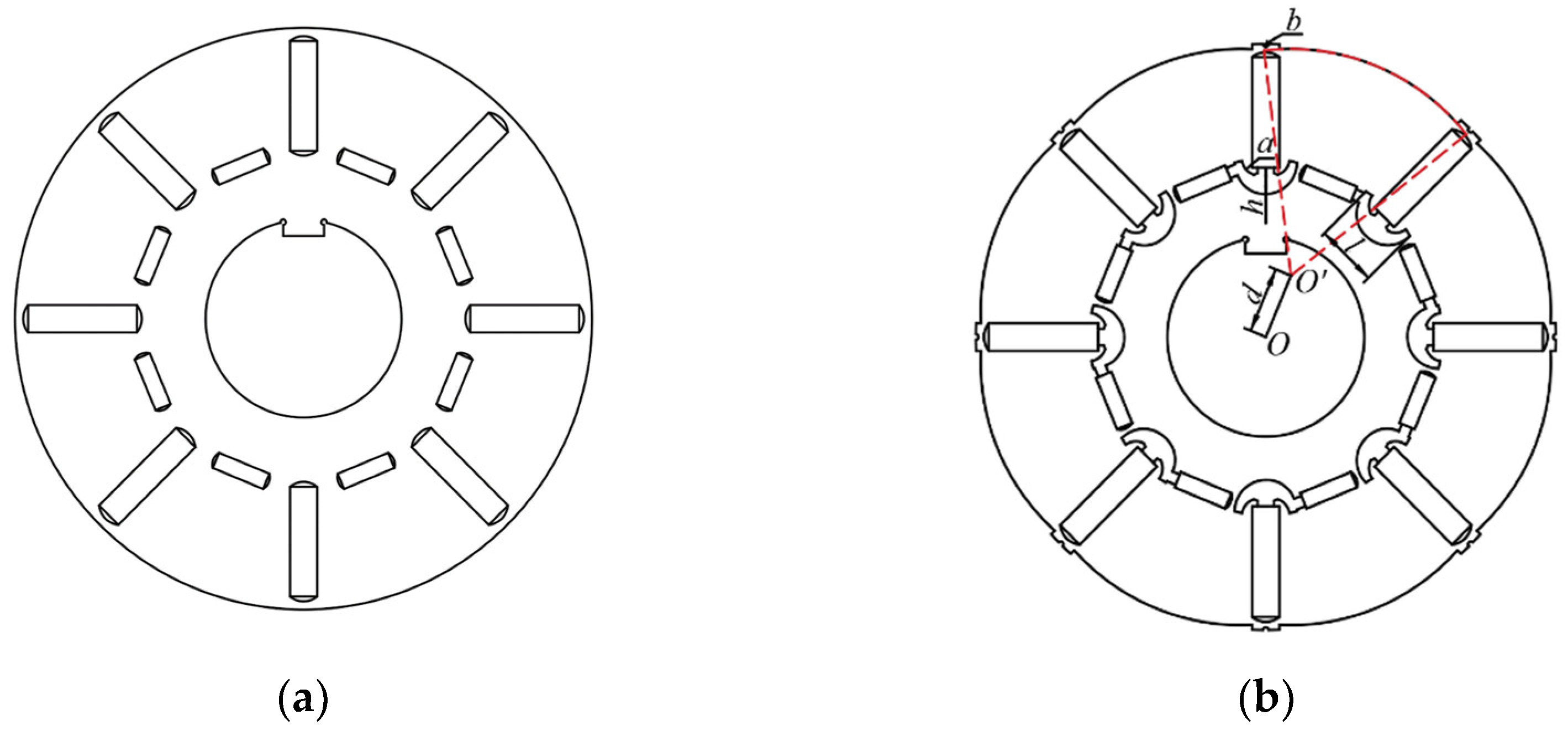
The combined magnetic pole PM rotor is the main component of the motor, and its magnetic barrier is the key to affecting the performance of the motor. To obtain a motor with a higher performance index, it is necessary to optimize the structure of the combined magnetic pole PM rotor. The structure of polar eccentricity changes the length of an air gap and makes the length of the air gap uneven. Changing the shape of the magnetic barrier can change the direction of magnetic field lines inside the rotor and reduce the magnetic leakage of the permanent magnetic steel itself. As shown in Figure 6, d is the pole surface offset, b is the radius of the welding groove, h is the height of the anchor type magnetic barrier, l is the width of the anchor type magnetic barrier, and a is the radius of the teeth of the anchor type magnetic barrier.
Based on the correlation mechanism between the structural parameters of the combined permanent magnet rotor barrier and the complex characteristics of the influence of the structural parameters of the combined pole permanent magnet rotor barrier on the performance of the motor. Within the allowable range of design variables, the traditional optimization strategy for a single parameter makes it difficult to obtain the optimal multi-design parameter combination scheme. Therefore, it is very important to carry out reasonable objective optimization for the magnetic barrier structure of the combined magnetic pole PM rotor.
The Taguchi method is an objective optimization design method proposed by Japanese scholar Taguchi Xuanyi based on orthogonal experiments and signal-to-noise ratios. It combines an orthogonal experiment table and analyzes the optimum combination scheme of multi-design parameters with the least number of experiments [20]. Based on the finite element analysis, the Taguchi method is used to optimize the magnetic barrier structure of a combined permanent magnet rotor, to obtain the best combination scheme of multiple design parameters of a magnetic barrier for a combined permanent magnet rotor.
For the HEDM, cogging torque (Tcog), average torque (Tavg), and distortion rate of back EMF (THD) are the main indexes to evaluate its performance, while ensuring that the torque fluctuation coefficient does not increase. Therefore, the distortion rate of back EMF becomes the primary optimization objective, the groove torque is the second optimization objective, the average torque is the third optimization objective, and the torque fluctuation coefficient is the constraint condition. The magnetic barrier structure of the combined magnetic pole PM rotor is optimized. Therefore, it is necessary to ensure that Tcog and THD are as small as possible and Tavg is as large as possible. Cogging torque (Tcog), average torque (Tavg), and distortion rate of back EMF (THD) are calculated as follows:
T cog α = L ef B σ 2 C T μ 0 π R 2 2 R 1 2 × n = 1 K sk n sin n N L b 0 2 sin n N L α p π N p sin n N L α 1 2 n N L α s
T ave = T max + T min 2
THD = U 3 2 + U 5 2 + U 7 2 + + U n 2 U 1 × 100 %
where μ 0 is the permeability of air, Lef is the effective axial length, B σ 2 represents the square of air gap magnetic density, R1 and R2 are the inner and outer diameters of the air gap, Np represents the pole number, Ns is the slot number, NL is the least common multiple between Np and Ns, b0 is the angle of slot opening, α p is the magnetic-pole embrace, α s is the angle of the stator skew, α is the rotor position, Ksk is the skewing factor, Tmax and Tmin are the maximum and minimum output torques, U1 represents the fundamental component, and Un is the nth harmonic amplitude.
For the above three performance indicators, as shown in Figure 6, the pole surface offset (d) is selected as the optimization factor A, the radius of the welding groove (b) is taken as the optimization factor B, the height of the anchor type magnetic barrier (h) is taken as the optimization factor C, the width of the anchor type magnetic barrier (l) is taken as the optimization factor D, and the radius of the teeth of the anchor type magnetic barrier (a) is taken as the optimization factor E. This paper adopts mixed-level optimization. Six levels were selected for the first optimization factor, and three levels were selected for the last four optimization factors. Based on the appropriate selection range of parameters and the allowable range of process design variables, the level of each optimization factor is determined. Table 2 shows the optimization factor level setting.
For the optimization factor in the table, if a comprehensive experimental scheme is adopted, 6 × 34 = 486 experiments need to be carried out, with a large number of experiments and a long design cycle. The L18 orthogonal table is selected to design the orthogonal experimental scheme, and reliable results can be obtained from only 18 experiments. The orthogonal experimental design is shown in the table. Table 3 shows the established mixed-level orthogonal experimental matrix and Tcog, Tavg, and THD under various experimental conditions. The numbers (1, 2, 3, 4, 5, and 6) in the table represent the corresponding level values of each optimization factor in the table.
The overall average value of the experimental results can be expressed by Equation (7) and the results are shown in Table 4.
m ¯ = 1 18 i = 1 18 m i
Through a numerical analysis of Table 3, the average value of each performance indicator under each factor level can be calculated, and then the influence rule of each factor on the average value of each performance indicator can be obtained. The calculation method of the average value of each performance indicator at different level factors is shown in Equation (8).
M m P i = 1 3 m P i 1 + m P i 2 + m P i 3
where M is an average value, mPi1~mPi3 is the Performance index values of 3 experiments at factor P level i.
The influence of each factor on the average of each performance indicator is shown in Figure 7, and the specific values are shown in Table 5.
It can be seen from the influence of the above factors on each performance index that the horizontal combination of optimization factors that make Tcog minimum, Tavg maximum, and THD minimum are A5, B1, C2, D1, E3, A1, B3, C2, D3, E1, A6, B1, C3, D1, and E3, respectively. Obviously, the optimal combination of multiple parameters for each performance indicator is not uniform. Therefore, it is necessary to further conduct variance analysis on the experimental results to determine the proportion of influence of each optimization factor on each performance index, and then the optimal combination of multiple parameters can be obtained.
The expression for calculating variance is:
S S = 1 x i = 1 x M m ¯ 2
where SS is the variance and x is the horizontal value under a certain influence factor.
Table 6 shows the variance and specific gravity of each performance index for each factor level. In the table, the change of B has the greatest influence on Tcog, the change of A has the greatest influence on THD, and the changes of D and E have the greatest influence on Tavg. Based on the optimization objectives of Tcog minimum, Tavg maximum, and THD minimum, the selection of D and E is based on the maximum size of Tavg, the selection of A is based on the minimum THD, and the selection of B is based on the minimum Tcog.
According to the above analysis of the average value, the optimal combination of level factors for Tcog minimum, Tavg maximum, and THD minimum is A5, B1, C2, D1, E3; A1, B3, C2, D3, E1; and A6, B1, C3, D1, E3, respectively. Combined with variance and specific gravity analysis, the optimized level factor combination is determined as A6, B1, C3, D1, and E3. Namely, the pole surface offset (d) is 13 mm, the radius of the welding groove (b) is 0.3 mm, the height of the anchor type magnetic barrier (h) is 5.5 mm, the width of the anchor type magnetic barrier (l) is 9.5 mm, and the radius of the teeth of the anchor type magnetic barrier (a) is 12 mm.
3.2. Structure Optimization of Claw Pole Rotor with Brushless Electric Excitation

The rotor of the brushless electric excitation claw pole is a special magnetic pole, so the distortion rate of the air gap magnetic density waveform of the claw pole is serious. In order to solve this problem, it is necessary to optimize the claw pole structure. Table 7 lists the thickness of different claw heels and claw tips and the polar arc coefficient of different claw heels and claw tips.
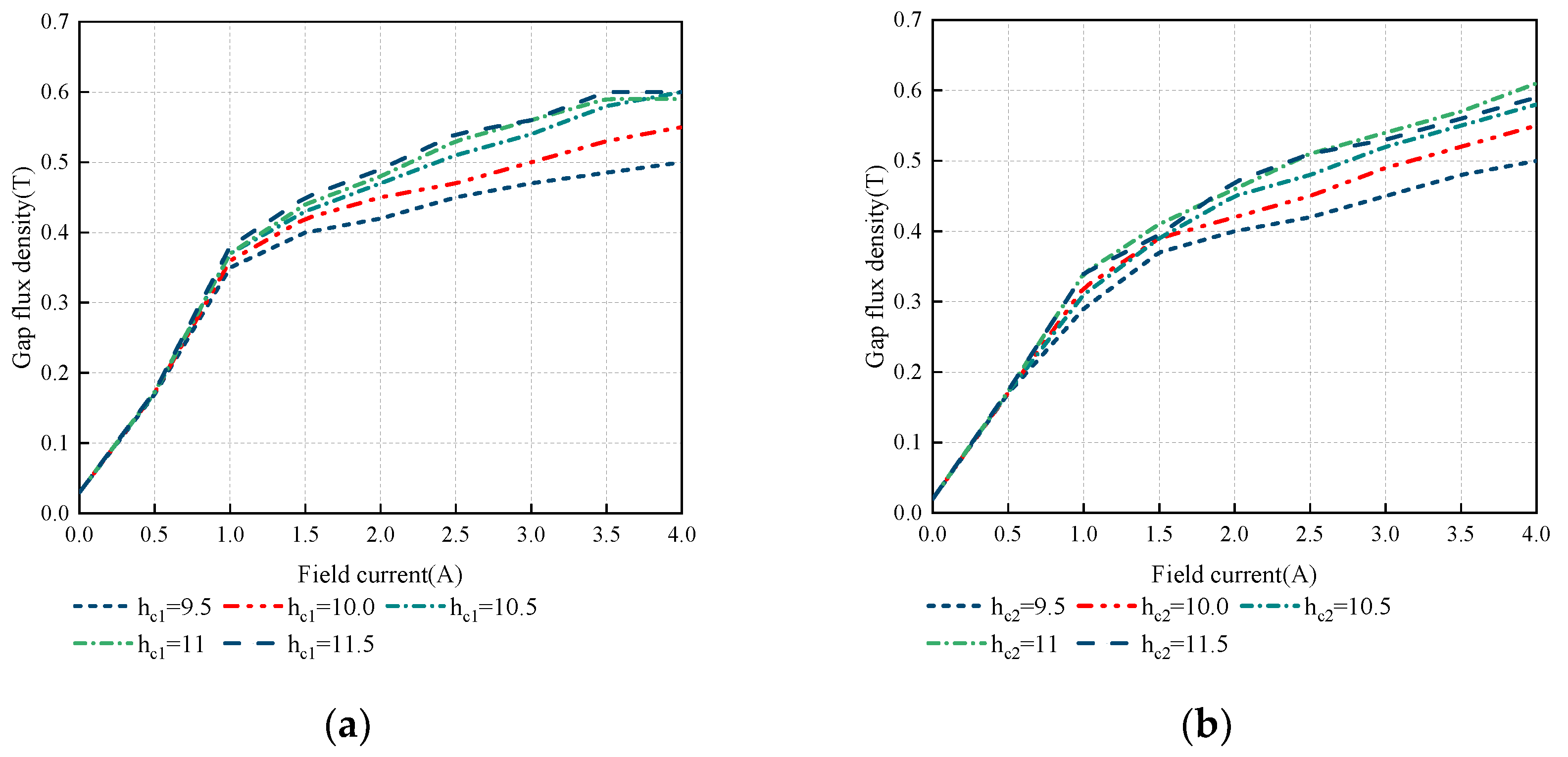
Figure 8 shows the influence of claw pole thickness on peak air gap flux density under different excitation currents. As shown in Figure 8a, the peak air gap magnetic density increases with the increase of excitation current. Within the range of excitation current, the peak air-gap magnetic density also increases with the increase in claw heel thickness. When the claw heel thickness is greater than 10.5 mm, the increase rate of the peak value of magnetic density slows down, and the claw heel thickness (hc1 = 10.5 mm) is the best parameter. As shown in Figure 8b, within the scope of the exciting current, with the increase in the thickness of the claw tip, the air gap flux density is also increasing. When the thickness of the claw tip is greater than 4 mm, the growth rate of the peak value of the air gap magnetic density slows down because the increase in the thickness of the claw tip weakens the switching ability of the axial and tangential magnetic fields. When the thickness of the claw tip (hc2) is 4 mm, a larger air gap magnetic field intensity can be obtained, which is the best claw tip parameter.
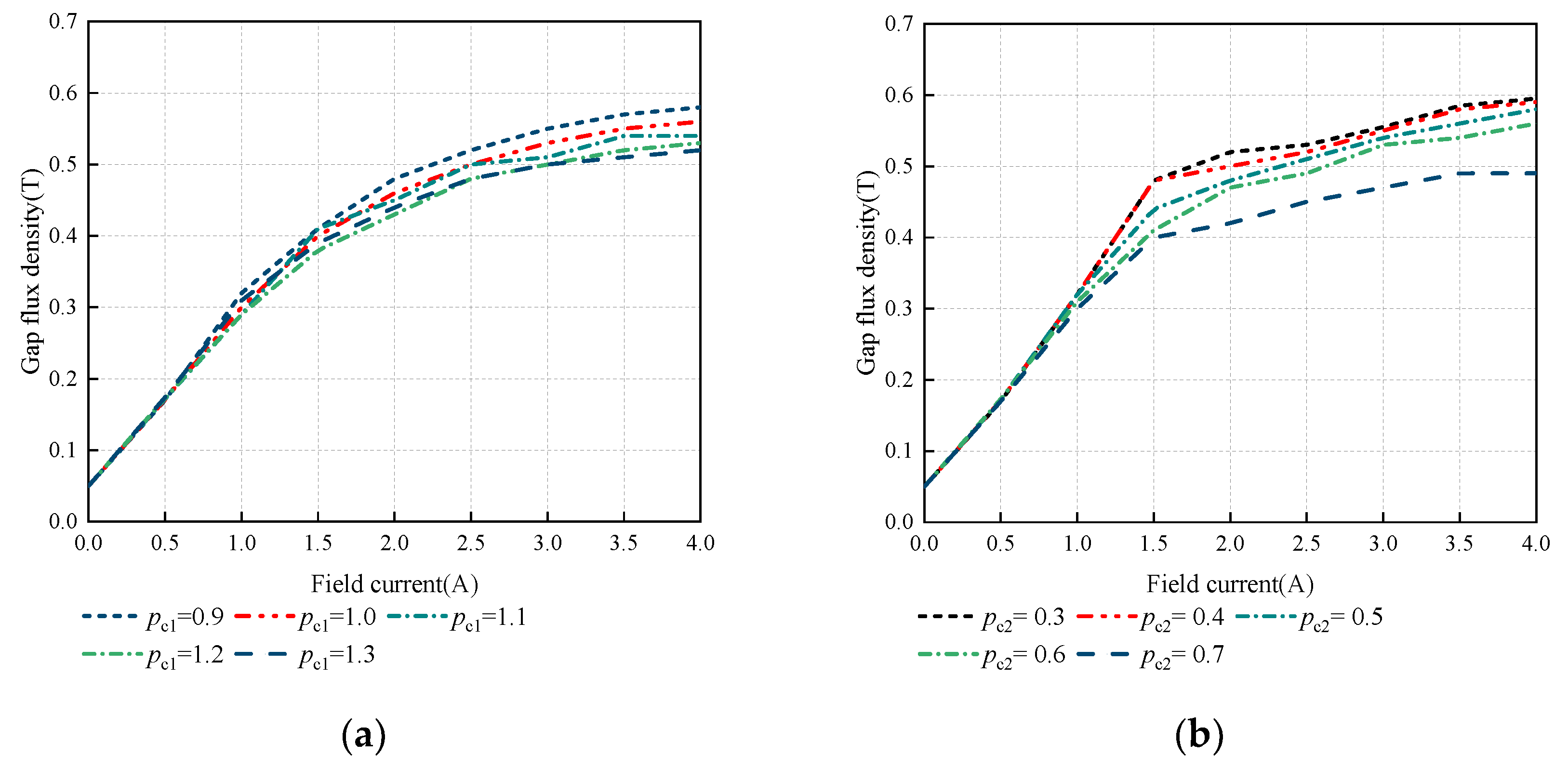
For the convenience of research, the width of the claw root and claw tip can be expressed by the claw root polar arc coefficient and the claw tip polar arc coefficient. Figure 9 shows the influence of the pole arc coefficient of claw on the peak value of air gap magnetic density under different excitation current. As shown in Figure 9a, with the increase of the pole arc coefficient of the claw root, the peak value of air gap magnetic density gradually decreases. Within the value range of the claw root, the magnetic density curve is relatively dense, which shows that the air gap magnetic density is less affected by the claw root. When the pole arc coefficient of the claw root is 1 mm, it has a larger air gap magnetic density. As shown in Figure 9b, with the increase of the pole arc coefficient of the claw tip, the air gap magnetic density gradually decreases. However, in the range of 0.3~0.5, the air gap magnetic density decreases slowly; pc2 = 0.4 mm is the best parameter.

4. Simulation Analysis and Prototype Experiment

4.1. Simulation Analysis of HEDM

4.1.1. Simulation Analysis of Combined Magnetic pole PM Rotor

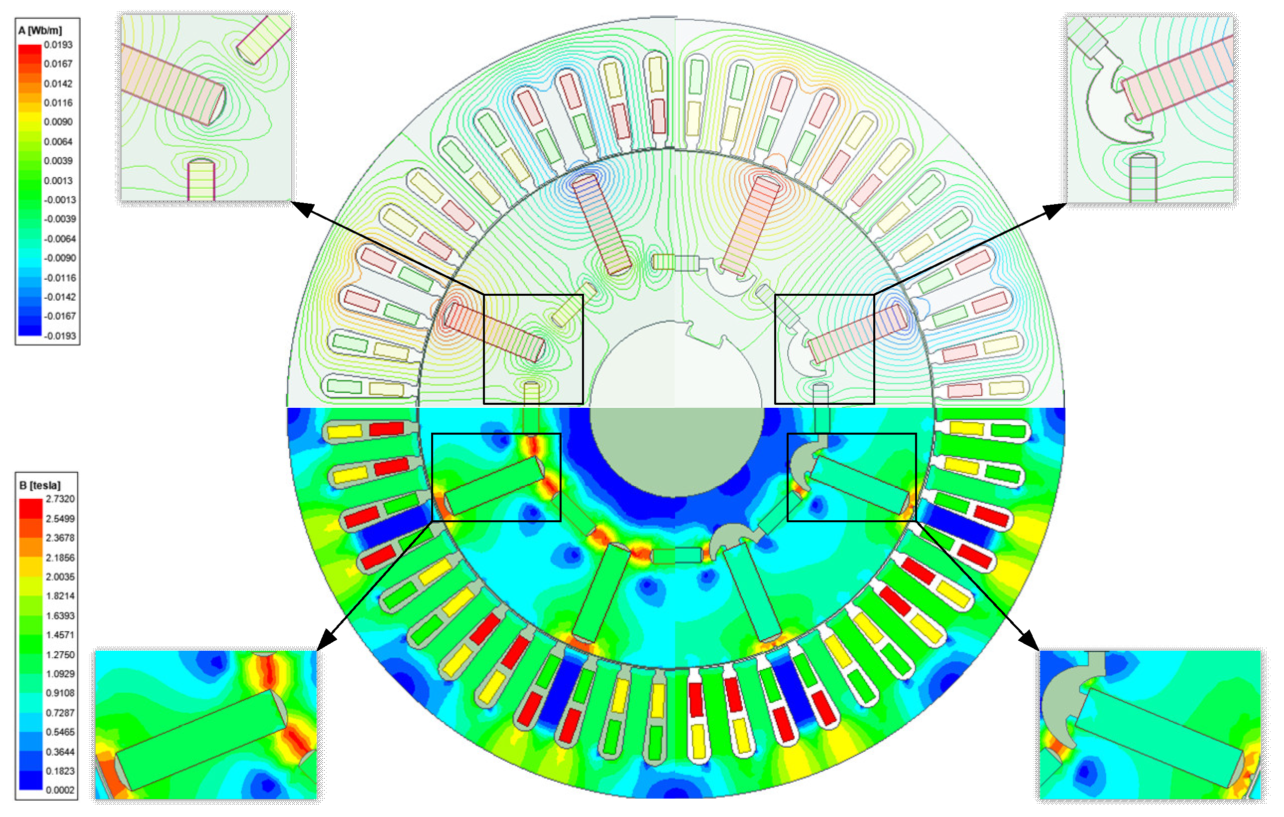
According to the above optimization scheme, the optimal size of the magnetic barrier is obtained, and the motor is designed accordingly. Figure 10 is the comparison diagram of magnetic force line direction and magnetic flux density of a combined magnetic pole permanent magnet rotor before and after optimization. It can be seen from the figure that the direction of the motor magnetic force line obtained by the finite element analysis is consistent with the path in the magnetic circuit analysis. The tangential magnetic field of the main magnetic pole and the radial magnetic field of the auxiliary magnetic pole cross the air gap in parallel, avoiding the irreversible demagnetization problem of the magnetic pole caused by the armature reaction. The anchor-type magnetic barrier solves the problem of magnetic flux leakage at the end of the main magnetic pole shaft side, and there is little magnetic flux leakage at the auxiliary magnetic pole near the anchor-type magnetic barrier side. The magnetic flux saturation of the rotor improves the utilization rate of the permanent magnet and verifies the magnetic gathering effect of the combined magnetic pole.
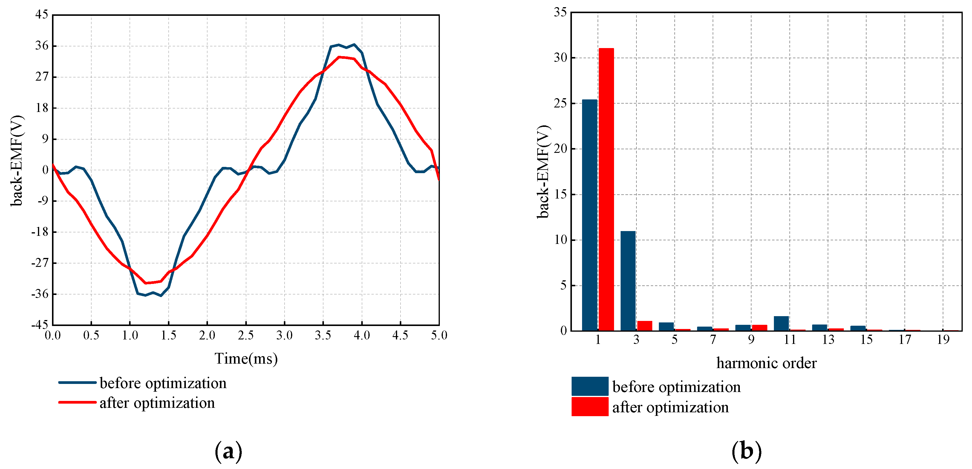
To verify the optimized electromagnetic characteristics of a combined pole permanent magnet rotor. Figure 11 shows the no-load back EMF waveform and harmonic amplitude of the combined pole permanent magnet rotor before and after optimization in one cycle. The back EMF waveform after optimization is more sinusoidal. According to the harmonic amplitudes of the no-load back EMF of the combined magnetic pole permanent magnet rotor before and after optimization, it can be seen that the fundamental wave amplitude is 25.38 V before optimization and 31.03 V after optimization, which is increased by 15.2%. The third harmonic is reduced from 10.93 V to 1.06 V, which reduces the distortion rate of the back EMF from 43.89% to 4.29%, down 39.6%. It shows that the optimized structure parameters have a significant effect on improving the back EMF.
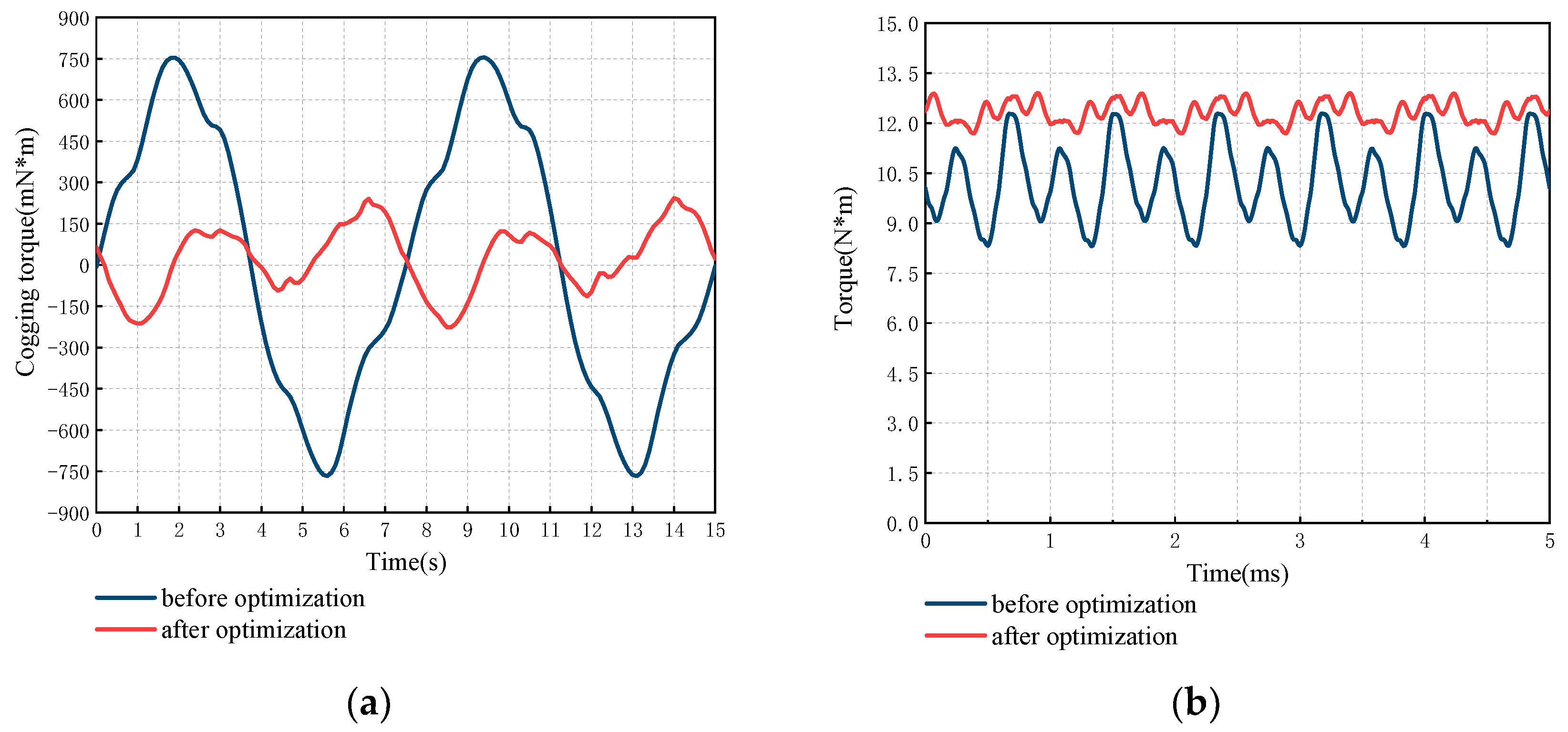
Figure 12 shows the cogging torque and output torque of the combined magnetic pole PM rotor before and after optimization. The maximum cogging torque after optimization is reduced from 754.61 mN·m to 241.94 mN·m. It can be seen from Figure 12b that the output torque fluctuates greatly before optimization, and its torque fluctuation coefficient is 39.1%. After optimization, the torque fluctuation coefficient is reduced to 4.8%, decreasing by 34.3%. Furthermore, the average torque after optimization increased from 10.18 N·m to 12.91 N·m, increasing by 21.15%, which verifies the correctness of the optimization method. Therefore, the reasonable optimization of the magnetic barrier structural parameters of the combined PM rotor can greatly change the electromagnetic properties of the HEDM, such as the cogging torque, the distortion rate of the back EMF, and the output torque, so as to improve the operational performance of the drive motor.

4.1.2. Simulation Analysis of Brushless Electric Excitation Claw Pole Rotor

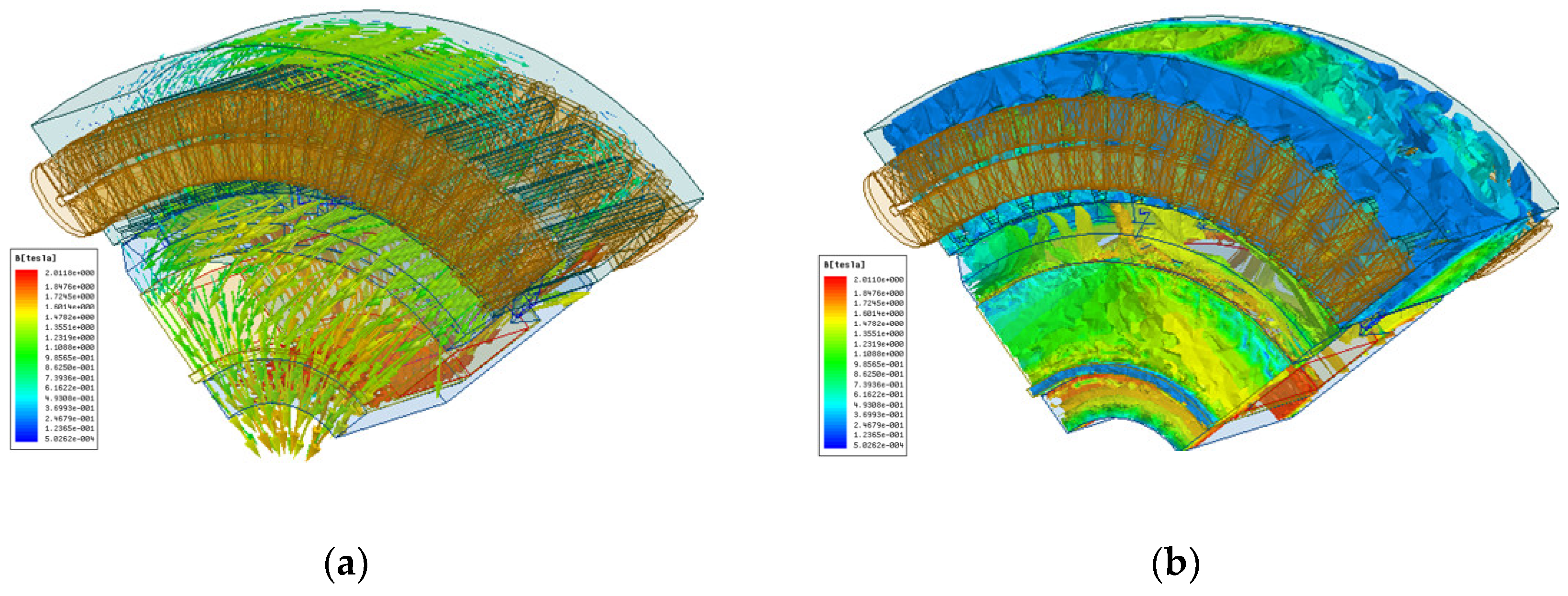
In accordance with the above claw pole optimization scheme, the optimum claw pole size is obtained, and the motor is designed accordingly. Figure 13 shows the flux vector diagram and magnetic density cloud diagram of the brushless excitation claw pole motor before and after optimization. The magnetic density of the brushless electric excitation claw pole motor is evenly distributed. The axial magnetic field excited by energizing excitation current transforms into a radial magnetic field through the claw pole structure. After reaching the main air gap, it returns to the main air gap through the stator and reaches the claw pole to form a complete closed circuit. The main flux path and leakage flux path of the claw are consistent with the theoretical analysis.
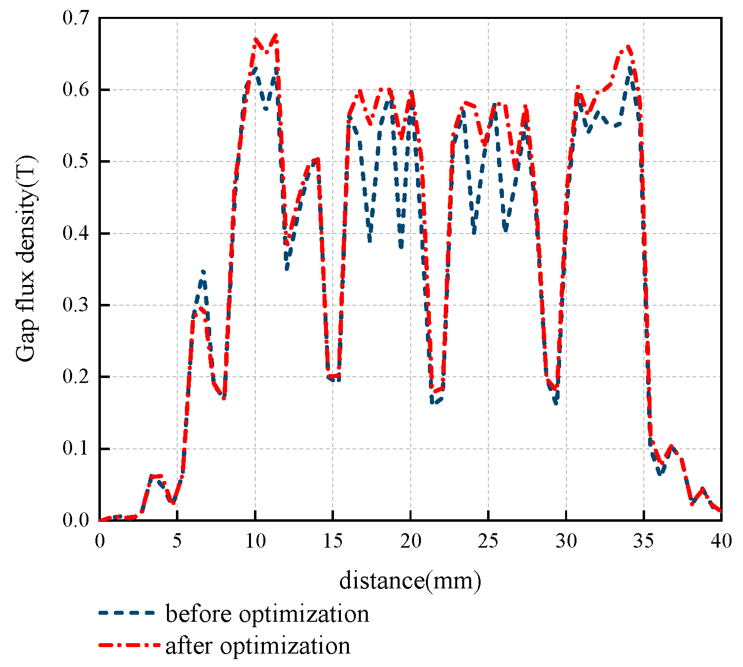
Figure 14 shows the comparison of the air gap magnetic density of the claw pole before and after optimization. The air gap magnetic density of the claw pole after optimization is more uniform, the air gap magnetic density waveform recesses are reduced, and the air gap magnetic density peak value increases. However, due to the structural characteristics of the claw pole motor, there are still some leakage conditions. Although the efficiency of the claw pole motor is relatively low, the magnetic field adjustment is convenient, which verifies the rationality of the structural design of the brushless electric excitation motor.

4.2. Prototype Experiment of HEDM

4.2.1. Cogging Torque Test

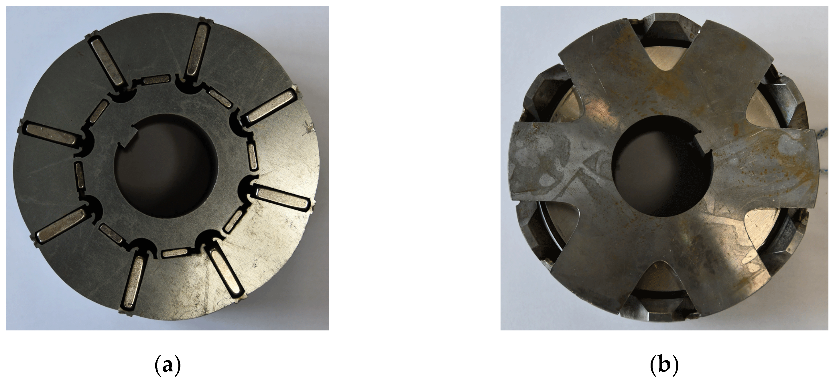
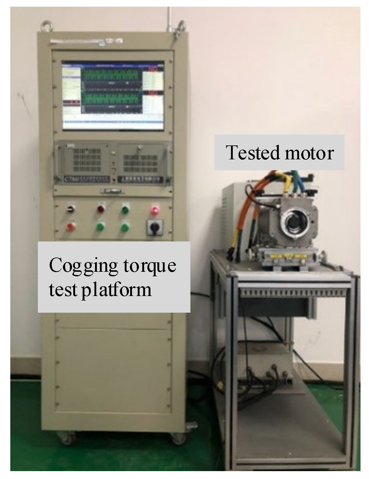
To analyze the correctness and rationality of simulation results, a prototype is made for experimental verification. Figure 15 shows the rotor structure of the HEDM. Figure 16 is an experimental diagram of a permanent magnet motor mounted on a slot torque tester.
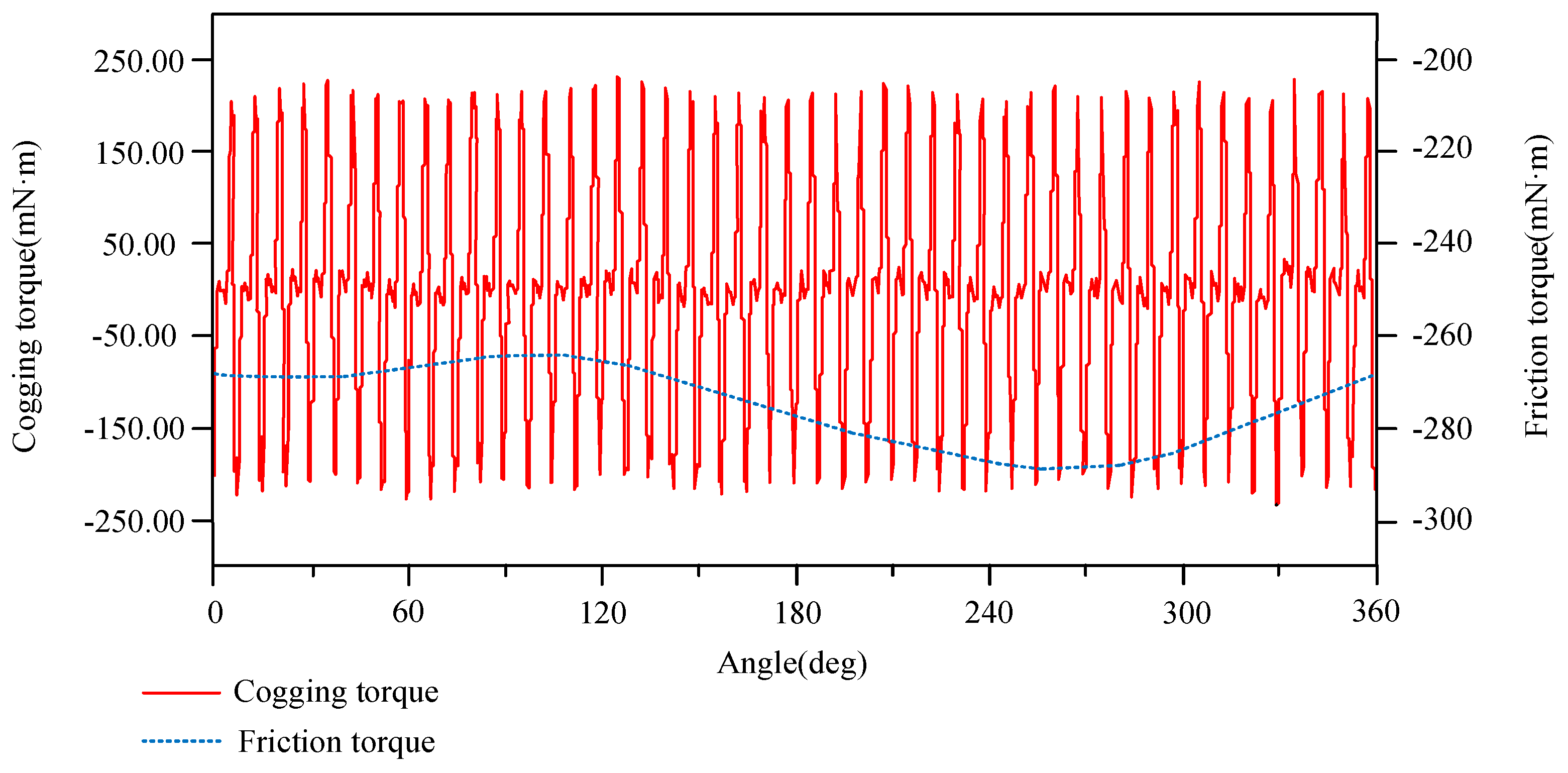
Figure 17 shows the experimental curve of cogging torque. The cogging torque of the motor is distributed periodically. Each rotation cycle of the motor corresponds to 48 positive peaks and 48 stator teeth. There is also a small cogging torque peak in the cogging torque cycle corresponding to each stator tooth, which is due to the influence of the laminated welding notch of the rotor silicon steel sheet. The maximum value is 236 mN·m, which is slightly less than the simulation value. The reason why the cogging torque test result is less than the finite element simulation data is not the large error of the test instrument but the ideal condition of finite element simulation. The actual prototype permanent magnet strength is smaller than the simulation value, which leads to the small cogging torque test results of the prototype permanent magnet rotor, but the error is within the allowable range.

4.2.2. Output Torque Performance Test

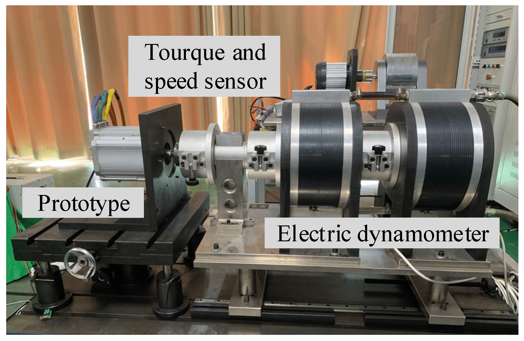
To test the magnetic modulation ability of the HEDM, the dynamometer is used to test the test prototype, as shown in Figure 18.
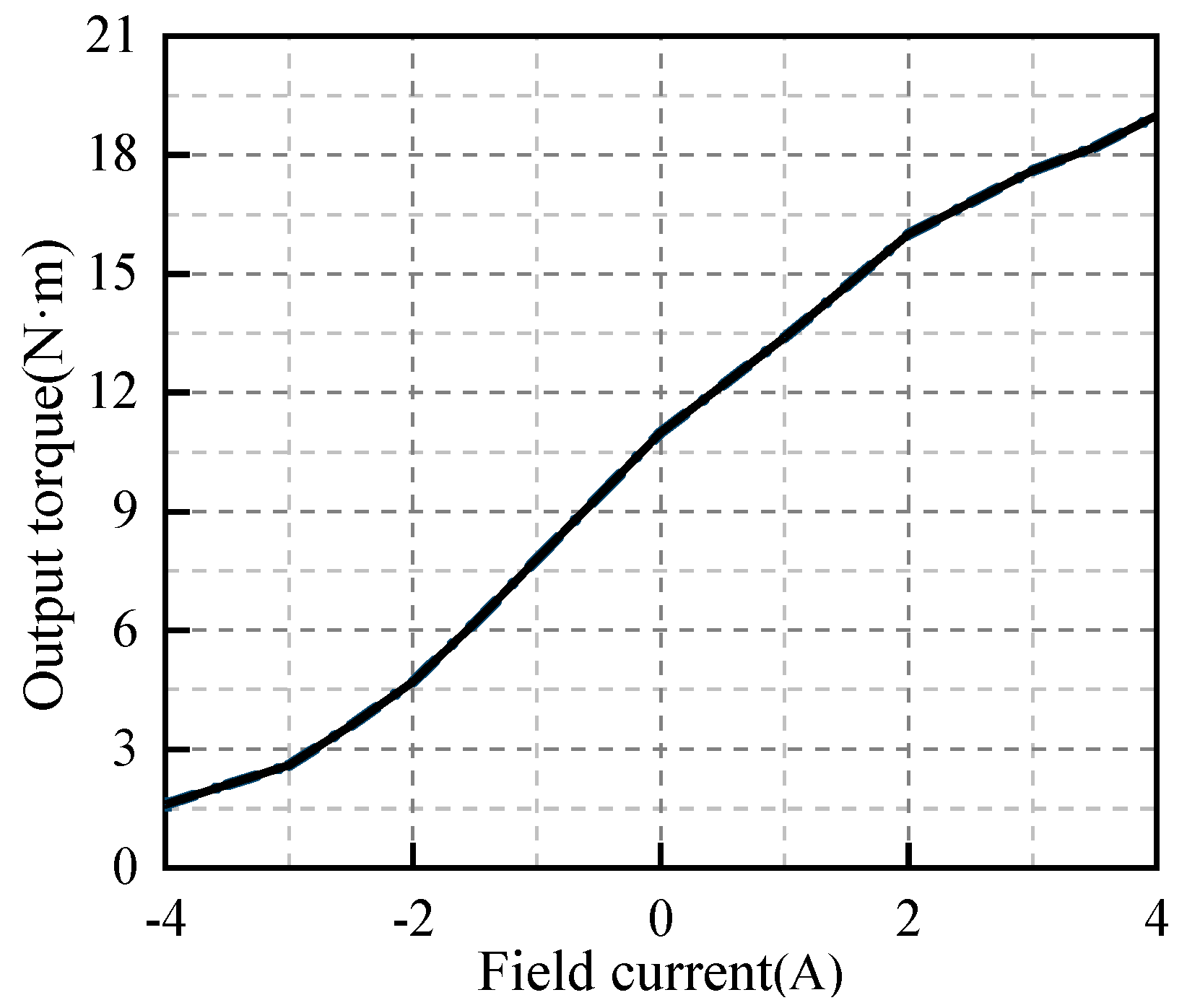
Figure 19 shows that the magnetic regulation characteristics of the HEDM are basically the same as the results of the finite element analysis. When the motor speed is 3000 r/min and the excitation current is 2A, the output torque of the HEDM is about 16 N·m. The output torque increases with the increase of the forward excitation current and decreases with the increase of the reverse excitation current. It is verified that the HEDM has a certain magnetic modulation ability.
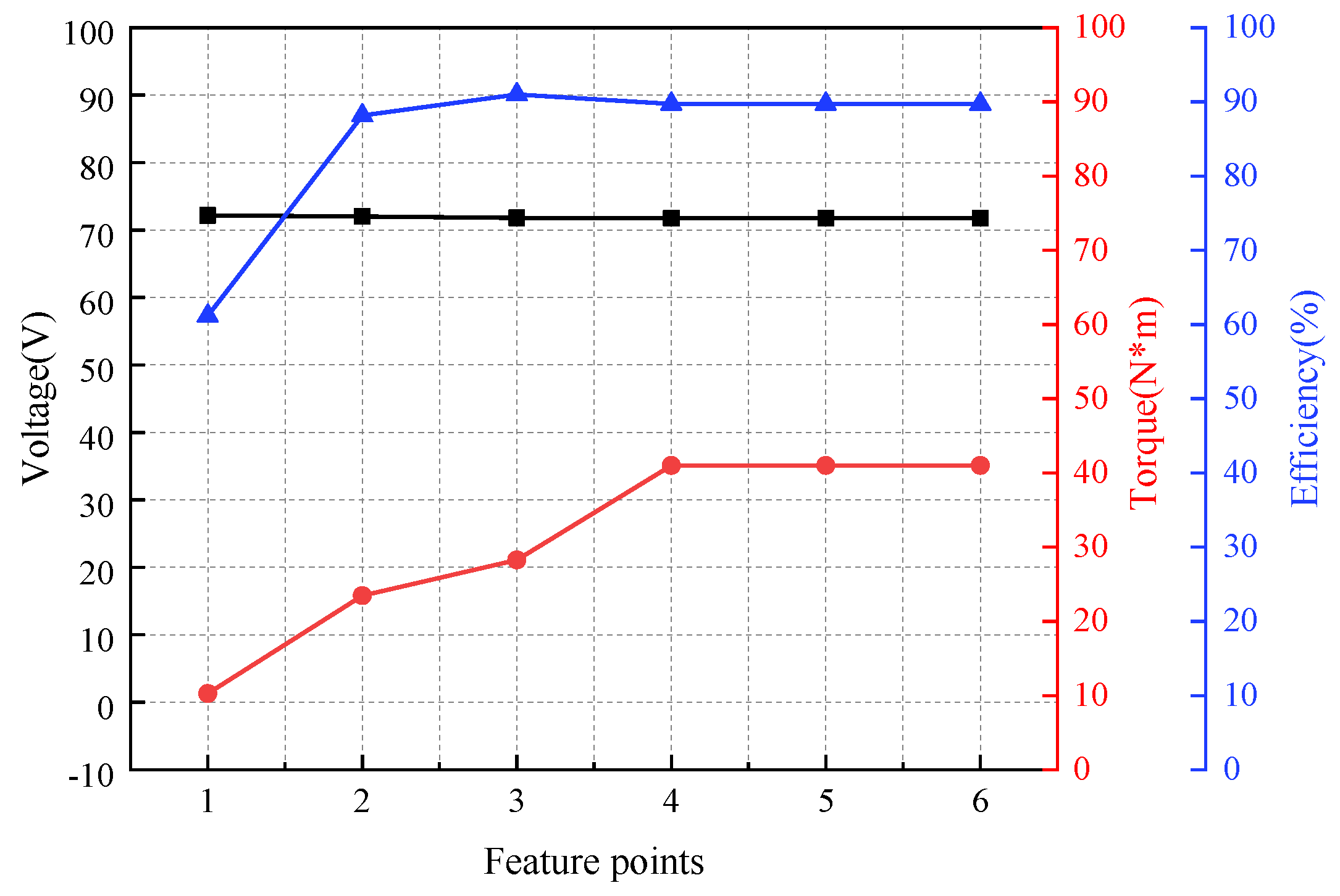
To obtain the output performance of the HEDM under different feature points, experimental tests are carried out on different feature points of the motor. Figure 20 shows the output characteristics of the motor at different feature points. Table 8 shows the experimental data for feature points of the HEDM under loading. The abscissa in Figure 20 represents the various feature points in Table 8, respectively. Figure 20 and Table 8 show that the rated torque of HEDM can reach 15.8 N·m and the maximum efficiency can reach 90.1%. The motor has good output characteristics and can meet the requirements of low-speed, high-speed, and constant power in new energy vehicles.

5. Conclusions

In this paper, a new HEDM for new energy vehicles is proposed, which adopts the structure of a combined magnetic pole PM rotor and brushless electric claw pole rotor sharing one stator side by side, so that the magnetic field regulation becomes convenient. In addition, this paper also draws the following conclusions:
The equivalent magnetic circuit models of the PM rotor and claw pole rotor are established, respectively. The new combined radial permanent magnet steel and tangential permanent magnet steel provide parallel magnetic flux. Compared with the single radial PM steel, the flux leakage is reduced, and the main flux is increased.
The Taguchi method is used to optimize the structure of the permanent magnet rotor, and the mixed horizontal orthogonal experiment matrix is established. The original groups of experiments are reduced to 18 groups of experiments, and the optimal solutions of five optimization factors are obtained, which improves the simplicity of this method. Using the method of control variables, the parameters of the claw root and claw tip are optimized by the calculated claw pole leakage flux coefficient, and the optimal solution of the claw pole structure is obtained, which makes the optimization of the claw pole rotor more targeted.
The pole surface eccentricity has the greatest influence on the distortion rate of no-load back EMF, the radius of the welding groove has the greatest influence on the cogging torque, and the width of the anchor type magnetic barrier and the radius of the anchor type magnetic barrier teeth have the greatest influence on the average torque. Compared with the performance before optimization, the cogging torque is reduced by 67.94%, the distortion rate of no-load back EMF is reduced by 39.6%, the average torque is increased by 21.15%, and the torque fluctuation coefficient is reduced by 34.3%.
In addition, thermal analysis and mechanical analysis are also required as constraints for multidisciplinary design optimization in order to ensure the reliability and safety of the motor. This will be the focus of machine optimization in the future.

Author Contributions

Conceptualization, X.Z. and S.Y.; methodology, S.Y.; software, S.Y.; validation, S.Y., M.X. and Y.Z.; formal analysis, S.H.; investigation, S.Y.; resources, A.W.; data curation, Y.Z.; writing—original draft preparation, S.Y.; writing—review and editing, S.Y.; visualization, Y.Z.; supervision, Z.G.; project administration, M.X.; funding acquisition, X.Z. All authors have read and agreed to the published version of the manuscript.

Funding

This research was funded by the National Natural Science Foundation of China (Grant no. 52275261 and 51975340).

Data Availability Statement

Not applicable.

Conflicts of Interest

Zhidong Gao is an employee of Weifang No. 1 Motor Factory Co., Ltd., Weifang 262127, China. Aichuan Wang is employee of Shandong Wuzheng Group Co., Ltd., Rizhao 262306, China. The paper reflects the views of the scientists, not the company.

References

  1. Lavrinovicha, L.; Dirba, J. Comparison of permanent magnet synchronous motor and synchronous reluctance motor based on their torque per unit volume. In Proceedings of the 2014 Electric Power Quality and Supply Reliability Conference (PQ), IEEE, Rakvere, Estonia, 11–13 June 2014; pp. 233–236. [Google Scholar]
  2. Hu, W.; Zhang, X.; Lei, Y.; Du, Q.; Shi, L.; Liu, G. Analytical model of air-gap field in hybrid excitation and interior permanent magnet machine for electric logistics vehicles. IEEE Access 2020, 8, 148237–148249. [Google Scholar] [CrossRef]
  3. Zhang, Z.; Wang, D.; Hua, W. Overview of configuration, design and control technology of hybrid excitation machines. Proc. Chin. Soc. Electr. Eng. 2020, 40, 7834–7850. [Google Scholar]
  4. Sulaiman, E.; Kosaka, T.; Matsui, N. High power density design of 6-slot–8-pole hybrid excitation flux switching machine for hybrid electric vehicles. IEEE Trans. Magn. 2011, 47, 4453–4456. [Google Scholar] [CrossRef]
  5. Zhang, X.; Du, Q.; Ma, S.; Geng, H.; Hu, W.; Li, Z.; Liu, G. Permeance analysis and calculation of the double-radial rare-earth permanent magnet voltage-stabilizing generation device. IEEE Access 2018, 6, 23939–23947. [Google Scholar] [CrossRef]
  6. Chai, W.; Kwon, J.; Kwon, B. Analytical design of a hybrid-excited wound field synchronous machine for the improvement of torque characteristics. IEEE Access 2020, 8, 87414–88742. [Google Scholar] [CrossRef]
  7. Namba, M.; Hiramatsu, K.; Nakai, H. Novel variable-field motor with a three-dimensional magnetic circuit. IEEJ Trans. Ind. Appl. 2015, 135, 1085–1090. [Google Scholar] [CrossRef]
  8. Wardach, M.; Paplicki, P.; Palka, R. A hybrid excited machine with flux barriers and magnetic bridges. Energies 2018, 11, 676. [Google Scholar] [CrossRef] [Green Version]
  9. Guo, X.; Wang, Q.; Shang, R.; Chen, F.; Fu, W.; Hua, W. Design and analysis of a novel synthetic slot dual-PM machine. IEEE Access 2019, 7, 29916–29923. [Google Scholar] [CrossRef]
  10. Mahmoudi, A.; Kahourzade, S.; Rahim, N.A.; Hew, W.P. Design, analysis, and prototyping of an axial-flux permanent magnet motor based on genetic algorithm and finite-element analysis. IEEE Trans. Magn. 2013, 49, 1479–1492. [Google Scholar] [CrossRef]
  11. He, J.; Li, G.; Zhou, R.; Wang, Q. Optimization of permanent-magnet spherical motor based on taguchi method. IEEE Trans. Magn. 2020, 52, 1–7. [Google Scholar] [CrossRef]
  12. Xia, C.; Guo, L.; Zhang, Z.; Shi, T.; Wang, H. Optimal Designing of permanent magnet cavity to reduce iron loss of interior permanent magnet machine. IEEE Trans. Magn. 2015, 51, 1–9. [Google Scholar] [CrossRef]
  13. Jannot, X.; Vannier, J.; Marchand, C.; Gabsi, M.; Michel, J.; Sadarnac, D. Multi-physic modeling of a high speed interior permanent-magnet synchronous machine for a multi-objective optimal design. IEEE Trans. Energy Convers. 2011, 26, 457–467. [Google Scholar] [CrossRef]
  14. Lee, S.; Kim, K.; Cho, S.; Jang, J.; Lee, T.; Hong, J. Optimal design of interior permanent magnet synchronous motor considering the manufacturing tolerances using taguchi robust design. IET Electr. Power Appl. 2014, 8, 23–28. [Google Scholar] [CrossRef]
  15. Zhang, W.; Shi, L.; Liu, K.; Li, L.; Jing, J. Optimization analysis of automotive asymmetric magnetic pole permanent magnet motor by taguchi method. Int. J. Rotating Mach. 2021, 2021, 1–9. [Google Scholar] [CrossRef]
  16. Wang, D.; Wang, X.; Kim, M.; Jung, S. Integrated optimization of two design techniques for cogging torque reduction combined with analytical method by a simple gradient descent method. IEEE Trans. Magn. 2012, 48, 2265–2276. [Google Scholar] [CrossRef]
  17. Zhao, W.; Zhao, F.; Byung, L.T.K. Optimal design of a novel v-type interior permanent magnet motor with assisted barriers for the improvement of torque characteristics. IEEE Trans. Magn. 2014, 50, 1–4. [Google Scholar] [CrossRef]
  18. Zhu, X.; Xiang, Z.; Quan, L.; Wu, W.; Du, Y. Multi-mode optimization design methodology for a flux-controllable stator permanent magnet memory motor considering driving cycles. IEEE Trans. Ind. Electron. 2018, 65, 5353–5366. [Google Scholar] [CrossRef]
  19. Ren, W.; Xu, Q.; Li, Q. Asymmetrical v-shape rotor configuration of an interior permanent magnet machine for improving torque characteristics. IEEE Trans. Magn. 2015, 51, 1–4. [Google Scholar] [CrossRef]
  20. Gope, D.; Goel, S. Design optimization of permanent magnet synchronous motor using Taguchi method and experimental validation. Int. J. Emerg. Electr. Power Syst. 2021, 22, 9–20. [Google Scholar] [CrossRef]
Figure 1. The structure of the hybrid excitation drive motor.
Wevj 14 00004 g001
Figure 2. Comparison diagrams of flux paths. (a) Magnetic flux path of initial structure. (b) Magnetic flux path of improved structure.
Wevj 14 00004 g002
Figure 3. Equivalent magnetic circuit model of combined pole permanent magnet rotor.
Wevj 14 00004 g003
Figure 4. Magnetic circuit diagram of claw pole motor with brushless electric excitation. (a) Electric excitation main flux path with forward current. (b) Electric excitation flux path with forward current.
Wevj 14 00004 g004
Figure 5. Equivalent magnetic circuit model of claw pole motor with brushless electric excitation.
Wevj 14 00004 g005
Figure 6. Schematic diagram of optimization parameters of combined magnetic pole PM rotor. (a) Initial structure and (b) Improved structure.
Wevj 14 00004 g006
Figure 7. Influence of optimization factor. (a) Cogging torque; (b) Output torque; and (c) Back-EMF distortion rate.
Wevj 14 00004 g007
Figure 8. Variation of air-gap flux density with the thickness of claw pole under different excitation currents. (a) The thickness of claw heel; and (b) The thickness of claw tip.
Wevj 14 00004 g008
Figure 9. Variation of air gap magnetic density with pole arc coefficient under different excitation currents. (a) Heel pole arc coefficient; and (b) tip pole arc coefficient.
Wevj 14 00004 g009
Figure 10. Comparison diagram of rotor before and after optimization. (a) Rotor magnetic field line trend comparison before and after optimization. (b) Rotor magnetic flux density comparison before and after optimization.
Wevj 14 00004 g010
Figure 11. Wave and harmonic of no-load back EMF before and after optimization. (a) Back-EMF wave. (b) Harmonic amplitude.
Wevj 14 00004 g011
Figure 12. Cogging torque and output torque before and after optimization. (a) Cogging torque wave. (b) Output torque wave.
Wevj 14 00004 g012
Figure 13. Diagram of claw pole motor. (a) Magnetic flux vector. (b) Flux density cloud.
Wevj 14 00004 g013
Figure 14. Comparison of air-gap magnetic density waveforms of the claw pole motor before and after optimization.
Wevj 14 00004 g014
Figure 15. The rotor structure of the HEDM. (a) Structure of combined magnetic pole PM rotor. (b) Structure of brushless electric excitation claw pole rotor.
Wevj 14 00004 g015
Figure 16. The cogging torque test platform.
Wevj 14 00004 g016
Figure 17. The cogging torque experimental curve.
Wevj 14 00004 g017
Figure 18. Dynamometer test platform.
Wevj 14 00004 g018
Figure 19. Magnetic modulation characteristic curve of prototype.
Wevj 14 00004 g019
Figure 20. Output characteristics of the motor at different feature points.
Wevj 14 00004 g020
Table 1. The main parameters of the hybrid excitation drive motor.
ParametersValueParametersValue
Rated power5 kWOuter diameter of rotor106 mm
Rated voltage72 VInner diameter of rotor36 mm
Rated speed3000 r/minDiameter of conductor0.8 mm
Phase3Number of conductors per slot8
Permanent magnetNdFe35Winding pitch5
Number of PM poles8Number of parallel winding9
Number of claw poles12Number of excitation winding turns320
Outer diameter of stator 160 mmExcitation Winding Diameter0.8 mm
Inner diameter of stator107 mmRated field current2A
Table 2. Motor optimization parameters and level values.
ParametersA (mm)B (mm)C (mm)D (mm)E (mm)
level 130.34.59.510
level 250.4510.511
level 370.55.511.512
level 49\\\\
level 511\\\\
level 613\\\\
Table 3. Mixed level orthogonal experimental matrix and results.
ABCDETcog (mN·m)Tavg (N·m)THD (%)
i = 111111351.9313.0827.43
i = 212222352.3613.1727.41
i = 313333620.9213.2527.34
i = 421122243.5212.5722.08
i = 522233480.2012.6522.08
i = 623311710.1612.4422.61
i = 731213273.7712.3317.03
i = 832321629.1612.7617.51
i = 933132850.4212.8617.84
i = 1041332520.1312.6912.92
i = 1142113584.5612.2012.82
i = 1243221936.7112.7413.67
i = 1351231236.4112.909.16
i = 1452312308.0812.488.81
i = 1553123423.9112.539.31
i = 1661323252.8912.534.80
i = 1762131555.2412.906.08
i = 1863212603.6612.585.64
Table 4. The overall average value of experimental results.
Tcog (mN·m)Tavg (N·m)THD (%)
Average value496.33512.70315.808
Table 5. Average of performance indicators.
FactorHorizontal ValueTcog (mN·m)Tavg (N·m)THD (%)
A1441.7413.1727.39
2477.9612.5522.26
3584.4512.6517.46
4680.4712.5413.14
5322.8012.649.09
6470.6012.675.51
B1313.1112.6815.57
2484.9312.6915.79
3690.9612.7316.07
C1501.6012.6915.93
2480.5212.7315.83
3506.8912.6915.67
D1472.0312.5215.72
2473.0912.7215.80
3543.8912.8815.90
E1569.9412.8016.08
2479.7012.7315.80
3439.3812.5815.56
Table 6. The proportions of influence of each optimization variable on optimization goal.
ParameterTcog (mN·m)Tavg (N·m)THD (%)
VarianceProportionVarianceProportionVarianceProportion
A12,627.48314.60 × 10−259.7856.1399.82
B23,860.1258.584.76 × 10−40.620.04190.07
C129.750.323.56 × 10−40.460.01150.02
D1130.852.782.17 × 10−228.20.00540.01
E2979.437.328.42 × 10−310.940.04520.08
Table 7. Parameters of the different claw pole.
ParameterClaw Heel ThicknessClaw Tip ThicknessPole Arc at the Claw HeelPole Arc at the Claw Tip
19.52.50.90.3
210310.4
310.53.51.10.5
41141.20.6
511.54.51.30.7
Table 8. Experimental data of motor load characteristic points.
Feature PointsVoltage (V)Electric Current (A)Torque (N·m)Rotate Speed (r/min)Efficiency (%)
Load point72.1610.501.3325657.3
Rated point72.0379.7915.8302787.0
Maximum efficiency point71.80100.921.1295890.1
Maximum output point71.76153.735.1266588.7
Maximum torque point71.76153.735.1266588.7
End point71.76153.735.1266588.7
Disclaimer/Publisher’s Note: The statements, opinions and data contained in all publications are solely those of the individual author(s) and contributor(s) and not of MDPI and/or the editor(s). MDPI and/or the editor(s) disclaim responsibility for any injury to people or property resulting from any ideas, methods, instructions or products referred to in the content.