1. Introduction
In the last decade, energy storage technology has been extensively researched and developed in the long term [
1,
2,
3,
4,
5,
6,
7]. Energy storage technology is no longer limited to being a mobile power source. It has many applications in all aspects of the power system. For the power generation side, energy storage units consume renewable energy and provide virtual rotational inertia to the power system as backup capacity on the grid side. Energy storage units are mainly used for frequency regulation of the power system and to achieve spatial and temporal load balancing. For the customer side, energy storage units are mainly used for emergency backup and tariff management, and energy storage technology can also improve the power quality on the customer side.
With the development of power transmission technology and power electronics, the electrification of rail transit has become a vital crossover direction and a hot technological growth point in the transport sector and the electrical sector [
8,
9,
10]. On the one hand, electrified drives reduce the use of mechanical structures such as drive bearings and internal combustion engines, reducing the size of the powertrain. The superior speed control performance of electric motors is unmatched by internal combustion engines, which brings technical advantages to the performance indicators of electrified transport. On the other hand, transportation electrification reduces the direct use of fossil fuels and greenhouse gas emissions, achieving good environmental benefits. The cost of power transmission is lower than that of fossil fuel transportation, which significantly reduces the energy cost of electrified transportation.
The electrification of transportation has strengthened the connection between the power and rail transportation systems. The reliability and economy of power supply have become essential factors in transportation. By adding energy storage to the power supply system of railways, energy efficiency can be increased, and the impact of power system failures can be reduced.
The application of energy storage in transport systems has been studied to some extent. Due to the mobility and off-grid operation of energy storage systems, electric vehicles with energy storage units at their core are gaining ground in the long term [
11,
12,
13,
14,
15]. However, the energy storage application in rail transit is still in its infancy. The electrified rail system is closely linked to the grid; its power supply system is integral to the grid. The power supply system of railways has a higher power rating than other modes of transport, and the load characteristics are intermittent and shocking. For these reasons, using energy storage technology in rail transit has unique characteristics.
This review searches several databases, such as SCI, IEEE/IET, Science Direct, and MDPI to summarize and organize the system architecture, circuit topology, and control strategies of energy storage in rail transportation applications in recent years. The keywords used for the search include, but are not limited to, rail transit, energy storage systems, traction circuits, and control strategies.
This paper summarizes the research results of energy storage systems in rail transit systems. Firstly, this paper summarizes the functional requirements and access methods of energy storage devices in rail transit power supply systems. Secondly, this paper summarizes the topologies and system integration methods corresponding to the common forms of energy storage in rail transportation. It analyzes the scenarios in which each topology and integration method is applicable. Third, this paper analyzes the specific control objectives and designs the corresponding control strategies for applying energy storage devices in rail transit systems. Finally, the prospects of energy storage applications in transportation and the problems that need to be focused on the prospect.
2. Rail Transit Demanded by Energy Challenges
With the increasing electrification of rail transit, the speed of trains is gradually increasing, while energy consumption is increasing. As a result, rail transit is facing several challenges in the energy sector, such as the additional load from rail electrification, power fluctuations, and voltage dips caused by train operating moments [
10,
11].
Traction power grids can be classified according to the type of buses as DC traction power network and AC traction power network.
The DC traction network is the typical traction grid structure of a metro. The system consists of a grid AC bus and a supply DC bus, with the metro trains being supplied directly from the DC bus. As the metro usually contains two trains opposite each other, the metro’s DC traction power supply system consists of two parallel DC buses. Metro systems are typically supplied from the national electricity grid and use rectifier substations to convert AC voltage into 750, 1500, or 3000 V DC voltage to power the trains.
Figure 1 shows the typical DC traction power network with multi-trains.
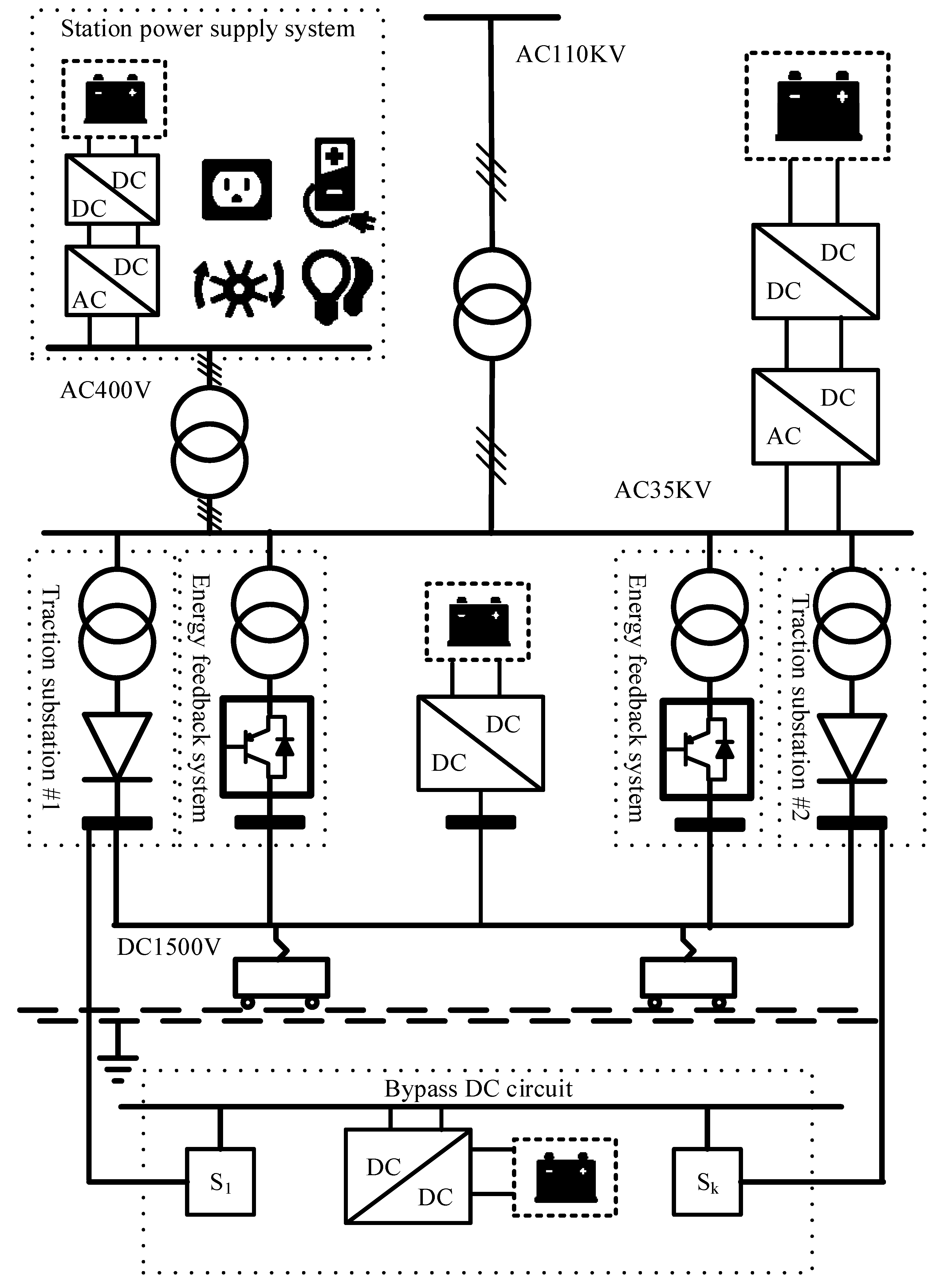
The DC power supply system is mainly used in urban rail transit, which uses the bilateral power supply and has a small power supply range. The topology of urban rail transit and the possible access location of the ground energy storage system is shown in
Figure 2. There are mainly two kinds of loads in the urban rail power supply system, station load and traction load, and the existing research is summarized.
When the energy storage system selects the AC400 V side or AC35 kV side for grid connection, it can realize the interaction between AC and DC grids through the energy feeder system. It can supply energy to station loads and utility loads. The minor network loss makes DC-side configuration energy storage the focus of research for rail transit configuration energy storage. The conventional energy storage configuration contains two types: the reversible substations and the railroad line configuration energy storage. The conventional energy storage configuration consists of two types: substation configuration storage and roadside ESS.
Reversible substations are obtained by configuring energy storage in the traction grid substation [
16]. This option has relatively low safety constraints and construction conditions and only needs to meet the general substation energy storage construction program. The reversible substation can provide energy storage for trains throughout the zone and does not require the railway to be shut down during maintenance. However, this technical solution lacks voltage stabilization, and the storage capacity needs to be determined in conjunction with the train operating schedule. The reversible substation can participate in the grid’s electricity trading, making the solution cost recovery possible. In addition, the maturity of the technology makes the application of this solution economical.
The roadside bypass ESS is another energy storage arrangement that places the storage units along the traction power lines alongside the tracks [
17,
18]. The roadside ESS can provide energy storage for internal trains within a certain zone to smooth out energy fluctuations within a certain zone. The advantage of this solution is that a single energy storage unit can be used for multiple trains and does not affect rail operations during maintenance. Roadside ESSs can significantly suppress voltage dips within the zone, but incur additional energy losses due to the need to use the traction system overhead lines to transfer energy. This solution requires a smaller number of energy storage units. It is less expensive overall, but it requires the energy storage to be pre-capacitated to consider the operating characteristics of the inter-district trains. This solution requires fewer energy storage units and is less costly overall, but it requires planning for energy storage capacity about the operating characteristics of the inter-district trains.
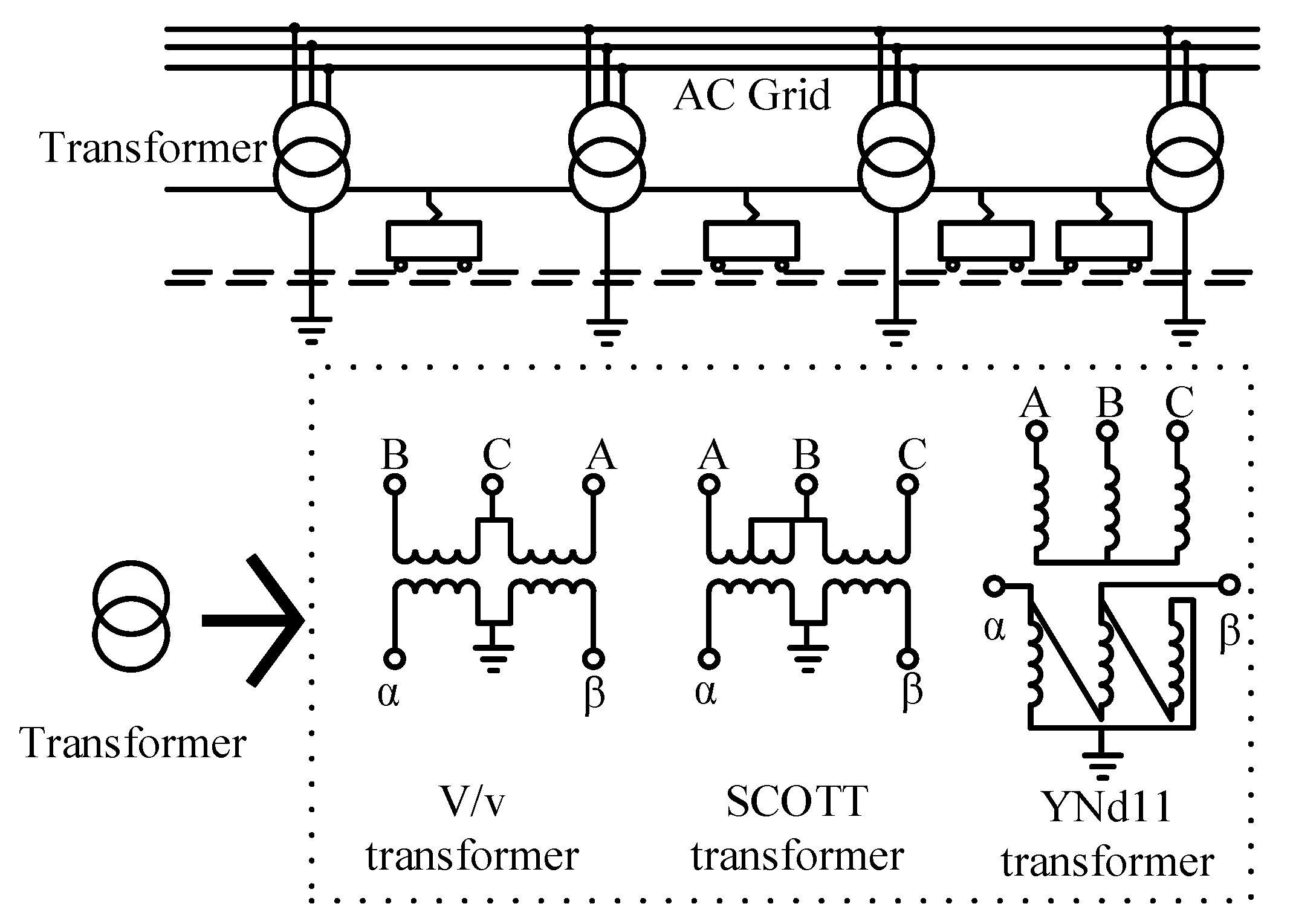
The AC traction network is the typical traction grid structure of railways. The AC traction power network supplies the trains via AC busbars based on traction transformers. The traction transformer is a step-down transformer as the grid supplying the traction system has voltage levels of 110 kV, 220 kV, and 330 kV, and the trains are supplied at 27.5 kV. There are three common forms of traction transformer wiring:
v/
v transformers, SCOTT transformers, and YNd11 transformers [
19,
20].
Figure 3 shows the typical AC traction power network with multi-trains.
The energy storage system can be configured with the station power system or an energy feedback device in AC rail power supply systems such as
Figure 4. AC rail transit substations can be divided into two types, same-phase power supply substations, and staggered-phase power supply substations [
21,
22,
23,
24]. In the same phase power supply substation, the role of the energy storage system is similar to that of the DC power supply system, which is mainly used to regulate power; in the wrong phase substation, the role of energy storage is mainly to balance the power between phases.
The DC traction and AC traction power supply have structural similarities. However, the busbar structures are different, and their energy storage devices have a similar system structure, differing only slightly in technical details.
3. The Way Energy Storage Is Arranged in Rail Transit
From the above analysis, it can be seen that the energy storage needs of rail transportation are based on power type energy storage as high power capacity type energy storage. The volume and performance index of energy storage is limited to a certain extent with the existing energy storage technology. See battery energy storage, supercapacitor energy storage, and flywheel energy storage as the most promising applications. To adapt to the needs of the traction grid or the onboard power supply system of a train, the above forms of energy storage require power conversion relying on power electronics technology, which has led to a variety of system structures for energy storage systems. This paper will present the structure of energy storage systems that meet the application scenarios of rail transit.
3.1. Types of Energy Storage in Rail Transit
Energy storage is widely studied as a technology for preserving and converting electrical energy. The differences in capacity and charging rates of the different energy storage methods make it possible to classify the energy mentioned above storage systems into two main categories in terms of external characteristics: power-based energy storage and energy-based energy storage. Among them, the power type energy storage has higher power density and charging/discharging rate. Still, the capacity cost of this type of energy storage device is higher. In contrast, the capacity type energy storage device has a larger energy storage capacity and lower energy storage loss. Still, the power limits the charging/discharging rate of this type of energy storage device. The classification of energy storage methods is usually based on the charging/discharging time. The longer the charging and discharging time of an energy storage system, the more it tends to be a capacity-based energy storage system; conversely, the shorter the charging time of an energy storage system, the more it tends to be a power-based energy storage system.
Battery energy storage (BES) is the most common and widely researched form of energy storage. In the transport sector, the flexible configuration of battery energy storage makes it a regular onboard power source for electric vehicles. Batteries are the main form of onboard backup and onboard auxiliary power in areas such as aviation and marine. As for the rail sector, the fact that power supply systems mainly power trains makes batteries less used than in other transport areas.
The flywheel energy storage system is a type of energy storage system based on electromechanical energy conversion. This technology stores electrical energy in the form of kinetic energy in a flywheel rotating at high speed with the power electronic converter or the mechanical structure. Flywheel energy storage has a high energy density and a fast response time, and flywheel is entirely pollution-free. Flywheel energy storage also has limitations in its application, with its low-capacity density and high self-discharge rate. However, with the application of material technology and magnetic levitation technology, the operational efficiency of flywheel energy storage is gradually improving. Flywheel energy storage can store large amounts of instantaneous power and can be charged/discharged quickly. These characteristics match the energy characteristics of rail transit power supply systems, making rail transit a significant research and application area for flywheel energy storage.
Supercapacitors are new energy storage devices with electrical characteristics and physical structures different from conventional capacitors. Supercapacitors have a higher energy storage capacity and charge/discharge rate than conventional capacitors. In addition, supercapacitors have a long cycle life and high reliability. Due to the low power density of supercapacitor systems, they are mainly used as power-based energy storage systems. In rail transit, supercapacitors can effectively absorb the load fluctuations generated by train operation and can also be energy storage units for energy return. However, the higher price and lower individual energy storage capacity make it difficult to promote on a large scale. It usually needs to be used in conjunction with other capacity-based energy storage.
3.2. Structure of the Energy Storage System with Battery
The battery is the most widely used energy storage unit, and to accommodate many different voltage levels, two-stage converters are the usual topology for battery applications. The two-stage converter consists of an AC/DC converter and a DC/DC converter. Depending on the type of AC grid, AC/DC converters are either three-phase or single-phase. The DC/DC converter is connected directly to the battery and regulates the charging current or voltage. As the battery needs to switch between charging and discharging modes, the DC/DC converter must have energy flowing in both directions. Bi-directional converters can be divided into non-isolated bi-directional converters and isolated bi-directional converters. The structural diagram of a two-stage converter is shown in
Figure 5.
Non-isolated bi-directional circuits are simple in construction, cost-effective, and stable in operation. Standard non-isolated circuits include half-bridge bi-directional DC/DC converters, BUCK-BOOST bi-directional DC/DC converters, Cuk bi-directional DC/DC converters, and Sepic/zeta bi-directional DC/DC converters.
The half-bridge bidirectional DC/DC converters are the most common non-isolated converters. These bidirectional DC/DC converters are simple in structure. Still, if the system works in continuous current mode, the reverse recovery of the diodes is a severe problem, and the current is intermittent. The peak current flowing through the switching tubes will be massive. The topology of the half-bridge bidirectional DC/DC converter is shown in
Figure 6.
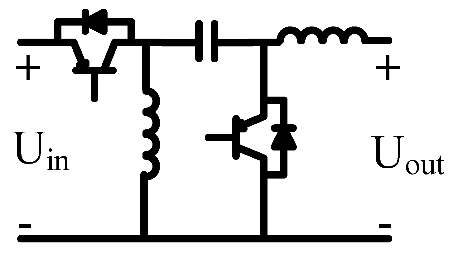
The BUCK-BOOST bidirectional DC/DC converter flange structure, in which the energy is stored and transferred through the inductor, is unsuitable for high-power applications. As with the half-bridge bidirectional DC/DC converter, the inductor current can be operated intermittently, but the peak current flow through the switching tubes becomes larger. The topology of the BUCK-BOOST bidirectional DC/DC converter is shown in
Figure 7.
The Cuk bidirectional DC/DC converter can be seen as a boost converter and a Buck converter in series with an optimized structure. During operation, the energy is transferred to the load via three conversions. The input supply current and the output load current are continuous, and the pulsations are minimal, which facilitates the input and output filtering. However, the efficiency of the Cuk circuit is relatively low and is rarely used in practical circuits. The structural diagram of the Cuk bidirectional DC/DC converter is shown in
Figure 8.
The Sepic/zeta bidirectional DC/DC converter is obtained by converting the diodes into bidirectional switches in the Sepic or zeta. The circuit topology and energy transfer are similar to the Cuk bidirectional DC/DC converter. The topology of the Sepic/zeta bi-directional DC/DC converter is shown in
Figure 9.
Non-isolated DC/DC converters are only suitable for low-power situations. They are suitable for auxiliary power supplies such as train lighting but not for high-power scenarios where rail traction grids are used. For high-power battery storage systems, isolated DC/DC converters are often used. Isolated converters use an isolation transformer as the isolating device. The standard basic topology types are isolated full-bridge bidirectional DC/DC converters, isolated half-bridge bidirectional DC/DC converters, and isolated push–pull bidirectional DC/DC converters.
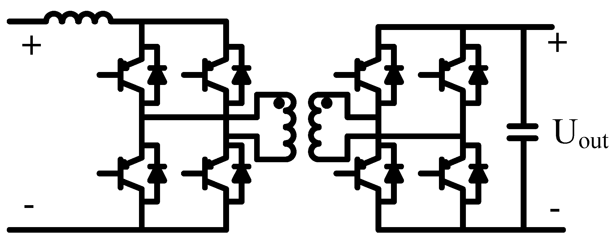
The isolated full-bridge bidirectional DC/DC converters are primarily used in high-power applications where the supply side is a current source. Due to the full-bridge conversion, the voltage and current stress on the individual power devices are reduced so that the same device can transmit more power, making it suitable for high-power applications. The topology of the isolated full-bridge bi-directional DC/DC converter is shown in
Figure 10.
The isolated half-bridge bi-directional DC/DC converter replaces some of the switching tubes of the full-bridge circuit with a neutral point clamp capacitor. Compared to full-bridge converters, they require a higher current capacity of the power device and a higher support capacitance, making them suitable for medium and high-power applications. The structural diagram of an isolated half-bridge bi-directional DC/DC converter is shown in
Figure 11.
Isolated push–pull bidirectional DC/DC converters are relatively simple in structure. Still, because of the large switching voltage spikes caused by transformer leakage, the switching tubes operate under harsh conditions and are suitable for low- and medium-voltage applications. The topology of the isolated push–pull bidirectional DC/DC converter is shown in
Figure 12.
The isolated DC/DC converters have a low energy transfer efficiency due to the presence of isolated devices, which can be improved by improving the structure of the isolated devices to achieve soft switching. In addition, isolated converters face problems such as component parameter degradation and resonance. However, for high-power energy storage in the rail transit sector, isolated DC/DC converters are an essential part of the energy storage system.
Energy storage systems need to integrate the battery for applications requiring more than one battery. Two common types of integration are single-converter integrated systems and multi-converter integrated systems [
25,
26].
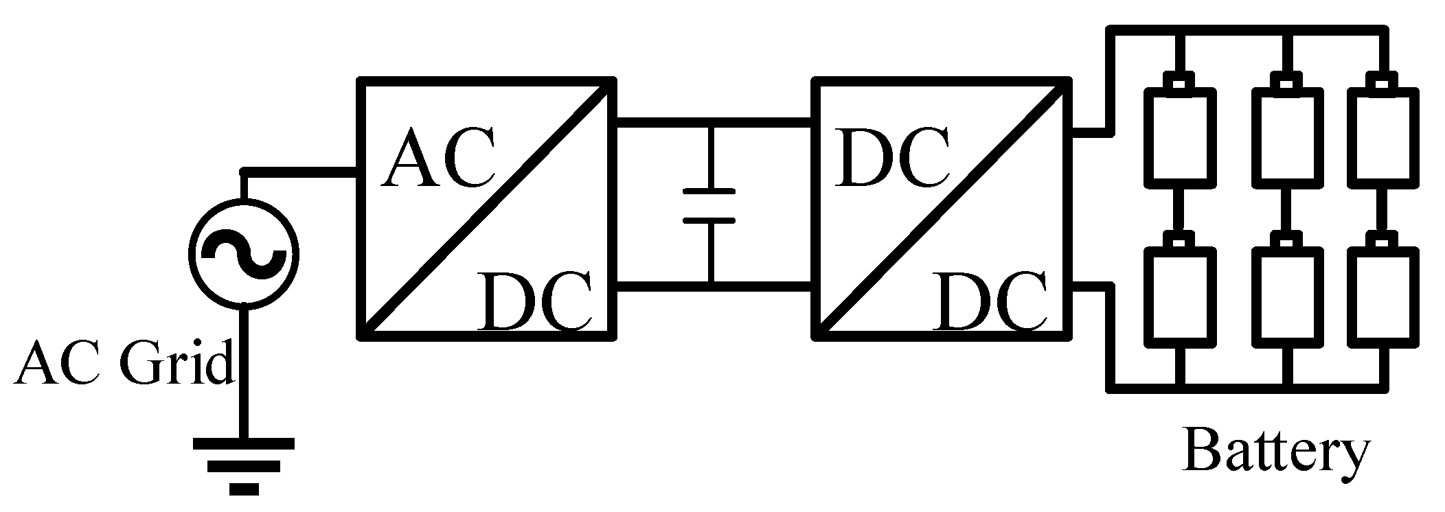
In single converter integrated systems, several battery clusters are connected to the same converter in series or parallel such as
Figure 13. In a single converter integrated system, several battery clusters are connected to the same converter in series or parallel. This technical solution requires fewer converters, operates efficiently and at a lower cost, and involves a more mature technology. However, this solution suffers from the problem of inter-cluster circulation. Because it is impossible to control individual battery cells independently, some of them still need to be fully utilized.
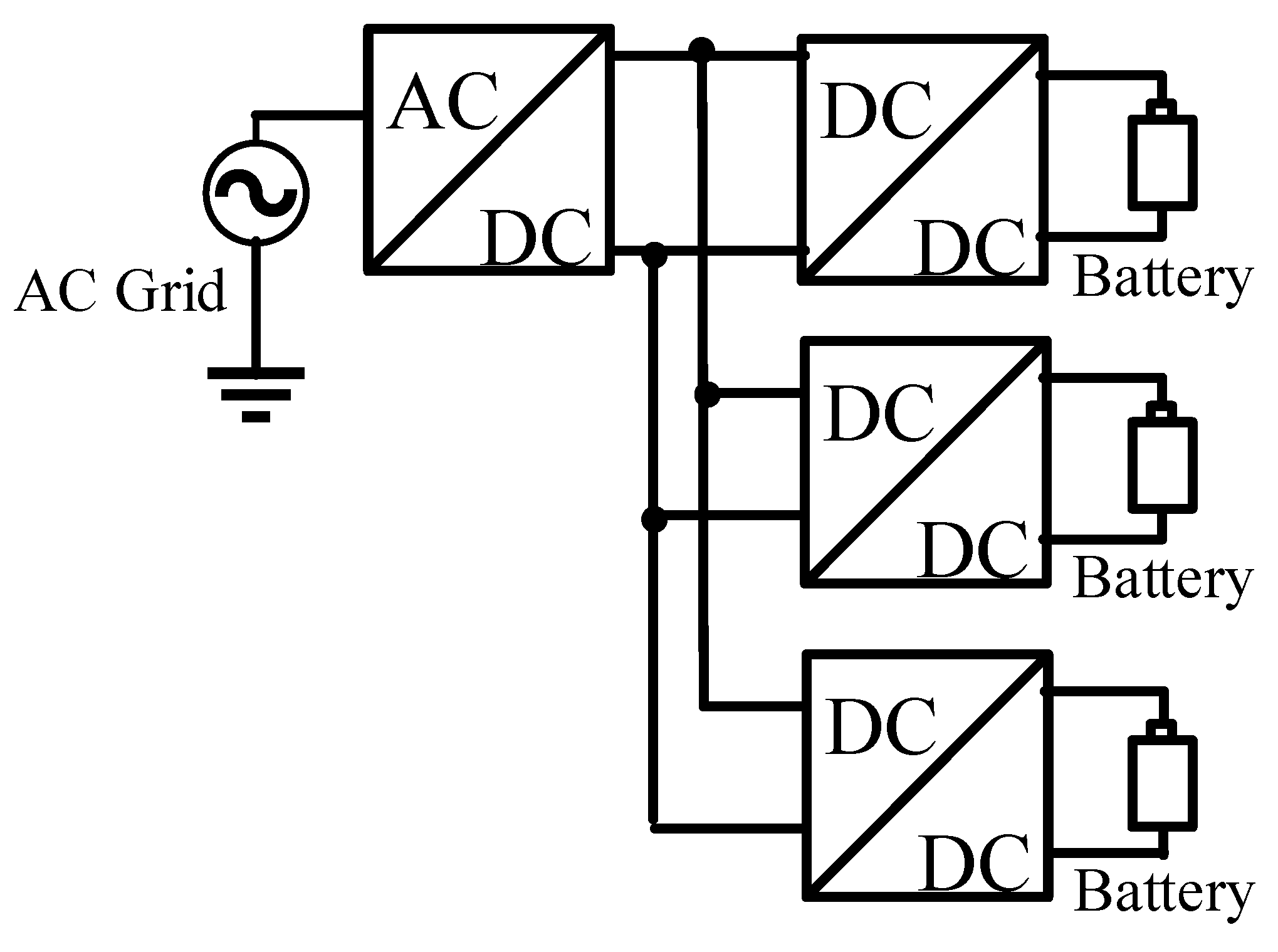
A system in a multi-converter integrated system where each cell is controlled by a separate DC/DC converter, which is finally brought together on the DC bus such as
Figure 14. This technical solution allows for the separate control of each battery and the individual removal of faulty battery clusters. This solution suffers from converter ringing and resonance problems which need to be eliminated using control. In addition, this solution has some disadvantages in terms of system cost and efficiency due to the most power electronics required.
3.3. Structure of the Energy Storage System with Super Capacitor
The capacity limitations of supercapacitors mean that they are rarely used on their own. Supercapacitors are often used in conjunction with a load which can be either an energy-dissipating element or another energy storage device [
27,
28,
29,
30,
31,
32,
33,
34,
35,
36].
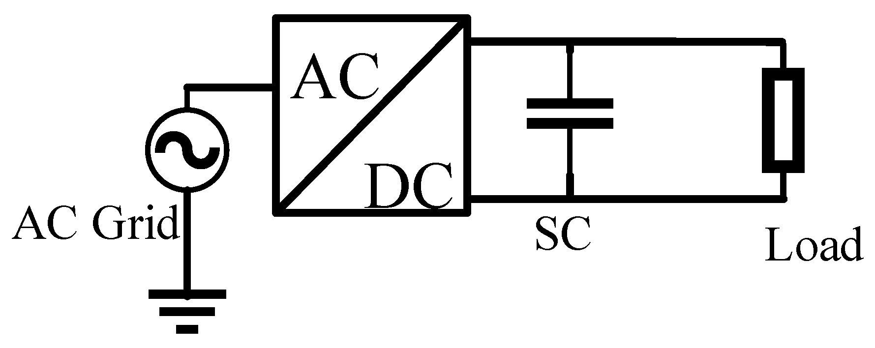
The simplest way to deploy a supercapacitor is to connect it directly in parallel with the load shown in
Figure 15. The supercapacitors in this topology combine the functions of DC-side voltage regulator capacitors. This topology is simple and does not enable control of energy flow, and the supercapacitor serves to eliminate power fluctuations on the DC side. The additional load from rail electrification, power fluctuations, and voltage dips are caused by train operating moments [
37].
The supercapacitor application circuit modified by a two-stage bi-directional converter is a feasible solution to achieve energy management, as shown in
Figure 16. A supercapacitor can replace the role of the DC bus capacitor in the topology, and the function of controlling the energy storage capacity can be achieved by controlling the voltage of the DC bus.
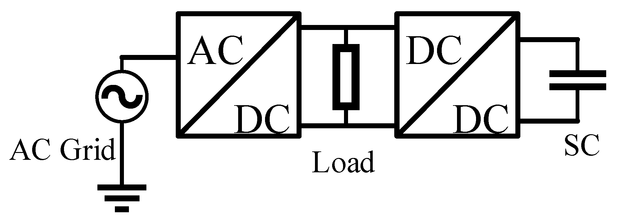
The supercapacitor’s need to support the DC bus voltage and energy storage in a direct retrofit bipolar bidirectional converter solution makes its control strategy complex such as
Figure 17. The degree of loading can be simplified by swapping the position of the load and the supercapacitor in the topology. This topology corresponds to adding a DC/DC converter supercapacitor energy storage system to the load [
38].
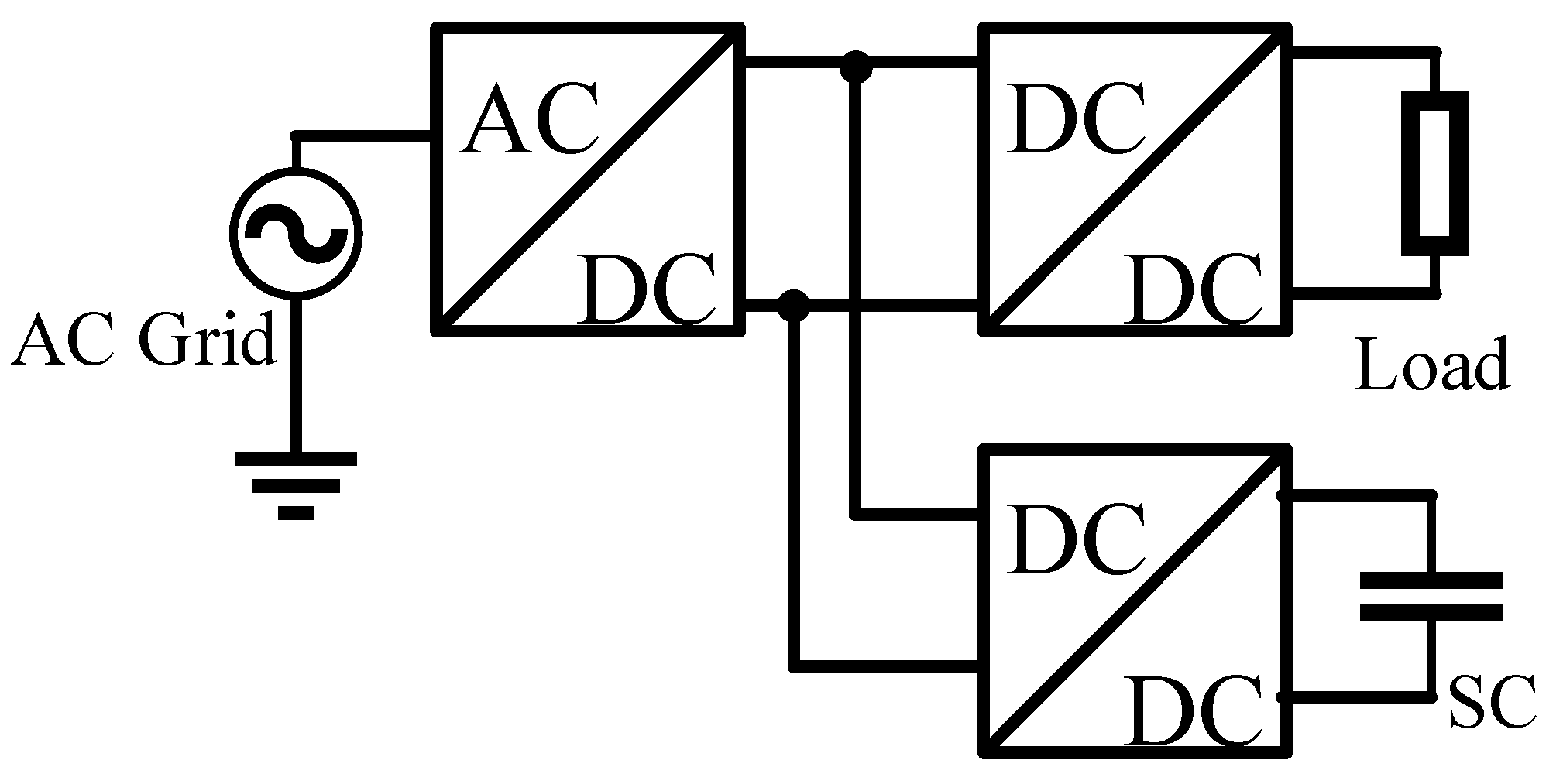
The other topology with additional supercapacitors is shown in
Figure 18. This topology connects the supercapacitor and the battery parallel to the DC bus by a DC/DC converter [
39,
40,
41].
The novel topology combines a supercapacitor with a DC/DC converter as an insertion circuit between the DC side of the converter and the load, shown in
Figure 19.
The plug-in converter topology modified from the boost circuit is shown in
Figure 20. This topology is simple, and the supercapacitor can provide power support during load fluctuations. The lack of freedom of control in this topology prevents the full use of the supercapacitor’s energy storage characteristics [
42,
43].
The topology containing the supercapacitor Quasi-Z source converter is shown in
Figure 21, which has additional control degrees of freedom to enable energy management of the supercapacitor. In addition, the topology can be used as an insertion circuit to increase the converter’s boost ratio and efficiently use the rectifier circuit’s dead time [
44].
3.4. Structure of the Energy Storage System with Flywheel
The flywheel energy storage requires external acceleration to transfer kinetic energy. Electric motor-based drives are the primary drive method for flywheel energy storage due to their excellent speed regulation and power capacity [
45,
46,
47,
48,
49,
50,
51,
52,
53,
54,
55]. The energy efficiency of rail transit systems using flywheel energy storage can reach 21.6% [
56].
The flywheel needs to obtain a high speed through the motor, making flywheel energy storage require a power electronic converter to regulate the speed of the motor such as
Figure 22. Direct AC converters are widely available for motor speed regulation circuits. The converter can be used for both load and power conversion, meeting the requirements of energy storage systems that require a bi-directional flow of energy. The topology is highly efficient as the energy only needs to be converted once.
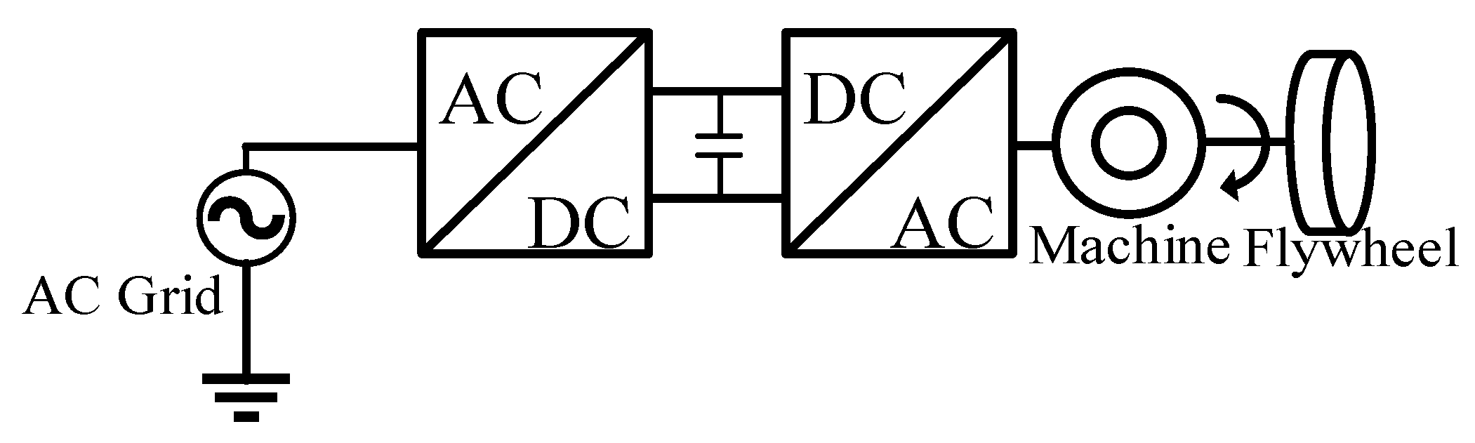
The indirect AC converter is another speed control circuit with a topology similar to the two-stage converter structure such as
Figure 23. The regulated capacitor between the two converters makes the DC side of the inverter comparable to a regulated power supply, avoiding energy fluctuations during the drive motor or grid connection [
52].
Replacing the DC regulator capacitor of the indirect AC converter with a boost converter increases the converter’s boost ratio to increase the motor’s speed range and meet the flywheel’s higher speed requirements such as
Figure 24.
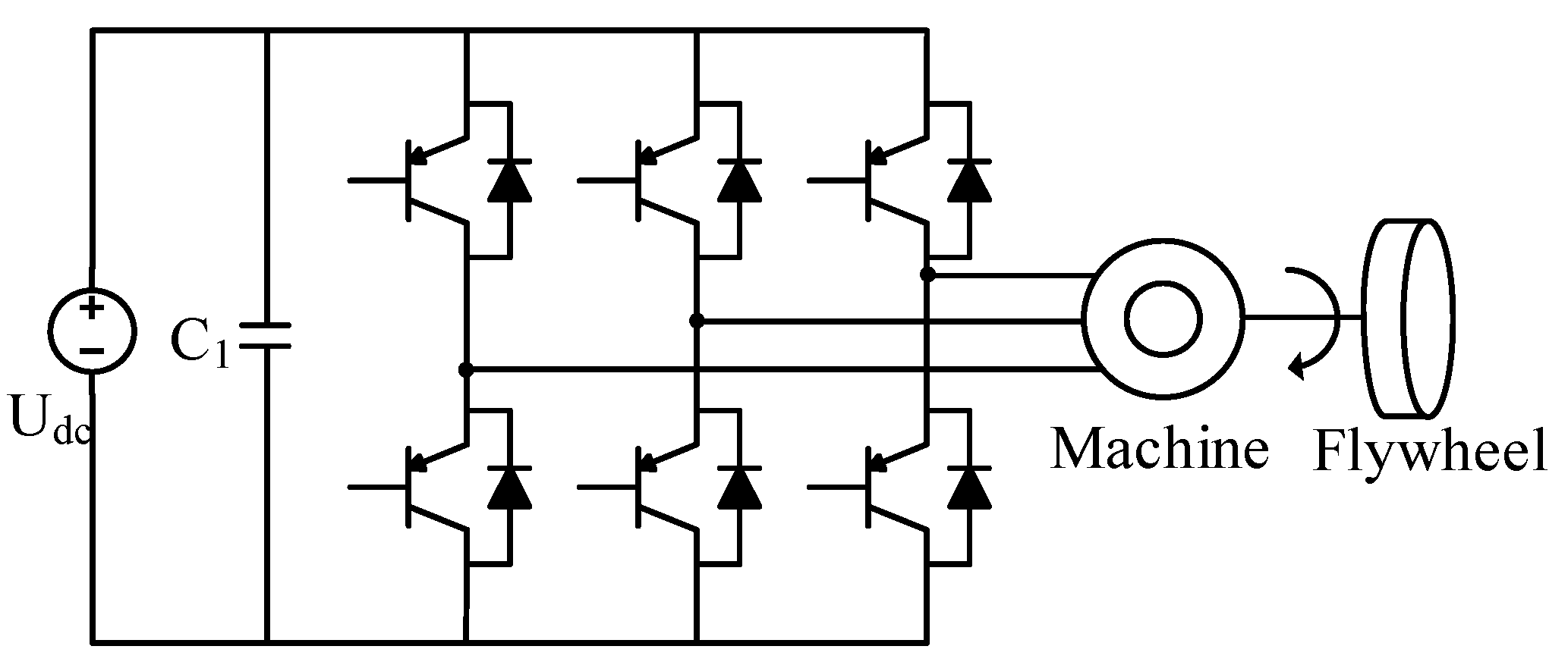
The inverter is directly connected to the motor and its performance will directly determine the capacity and power characteristics of the flywheel energy storage; the most common full-bridge inverter circuit topology is shown in
Figure 25.
For power levels more significant than the capacity of a single switching tube, a multilevel inverter can be used to drive the motor such as
Figure 26. This type of inverter increases the capacity of the inverter by increasing the shared voltage stress on the switching tubes.
Since the matrix converter omits the DC intermediate link such as
Figure 27, eliminating the bulky voltage regulator capacitors, it does not require a converter compared to direct AC converters. This is the reason matrix converters have a significant size advantage in flywheel energy storage. However, matrix converters also suffer from complex control and low voltage utilization, and their application prospects require further research.
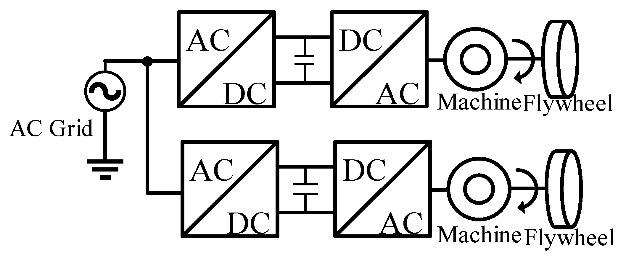
The DC bus integration scheme for flywheel energy storage is shown in
Figure 28, which integrates several inverters into the DC side of the same rectifier. The DC bus integration scheme is less prone to loop currents between converters and requires a relatively small number of devices.
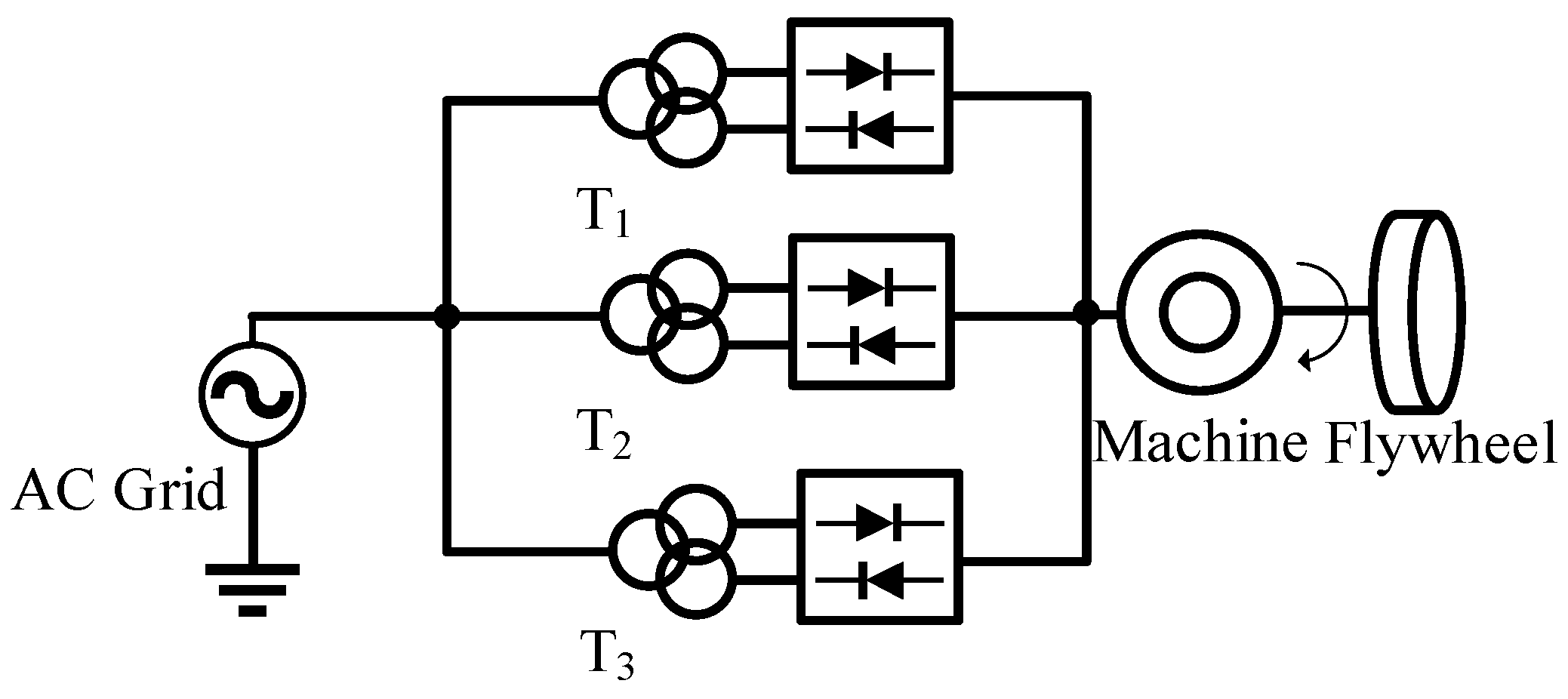
The AC bus integration solution is the direct parallel connection of several flywheel energy storage systems to an AC source (
Figure 29). This integration solution makes the multiple systems independent of each other, improving system reliability and reducing the performance requirements of the rectifier.
4. Energy Storage Control Strategy in Rail Transit
4.1. Control Strategy for Power Quality Management in Rail Transit
With the large-scale application of electrified rail transportation, the power quality problems in electrified railroads are becoming more and more prominent. One of the most prominent problems lies in three aspects: three-phase unbalance, harmonic pollution, and voltage fluctuation [
57,
58,
59,
60,
61,
62,
63,
64].
The three-phase unbalance in electrified rail transit is caused by the asymmetric power supply method of the traction transformer, which generates negative sequence currents in the power system. It is necessary to compensate for the negative sequence current. In this process, the four-quadrant operation capability of the power regulator is used to transfer the active current of the two supply arms dynamically, and the energy storage system plays the role of making up the power shortage in this process to reduce the negative sequence current and reduce the three-phase voltage unbalance. The compensation is divided into active and reactive current compensation, and the three-phase current vector diagram is shown in
Figure 30.
Active current compensation achieves the balance of active currents in both arms, and the active compensation currents in both supply arms can be expressed as
where
ISR and
ISL are active compensation current.
Ies is the practical value of the compensated transfer active current of the energy storage system, and its value is determined by the charging and discharging rules of the energy storage system.
After active current compensation, there is still a phase difference between the load current of the supply arm and the three-phase voltage on the grid side, and the phase difference needs to be corrected for reactive power compensation.
where
ILq and
IRq are the reactive compensation current,
Iaq and
Ibq are the reactive component of the current to be compensated,
Iap and
Ibp are active components of the current to be compensated.
Electrified rail transit traction systems use many high-power power electronics, making rail transit harmonics a significant part of grid harmonics. The energy storage device achieves the purpose of eliminating the harmonic current of the moving train by generating a compensation current of equal size and opposite phase to the harmonic current of the moving train, and the size of the harmonic compensation current to be generated as:
Harmonic compensation first needs to extract the harmonic current to obtain the reference command value of the energy storage converter, i.e., harmonic compensation current, and then realize the working mode discrimination according to the real-time power of load and the remaining capacity of the energy storage system to absorb the harmonic energy or release the compensation current with the opposite phase of harmonic current. At present, the research on harmonic compensation based on energy storage systems mainly focus on the converter control strategy, and there are relatively few studies on the capacity of energy storage devices, the charging and discharging threshold of energy storage, and the optimization of real-time charging and discharging power in the process of harmonic compensation.
Network voltage stability is the basis for safe train operation, and changes in train operating conditions are the main factor causing voltage fluctuations in the traction network. Priority should be given to using energy storage for active compensation and then controlling the four-quadrant converter for reactive power compensation if the voltage still cannot meet the requirements after active compensation.
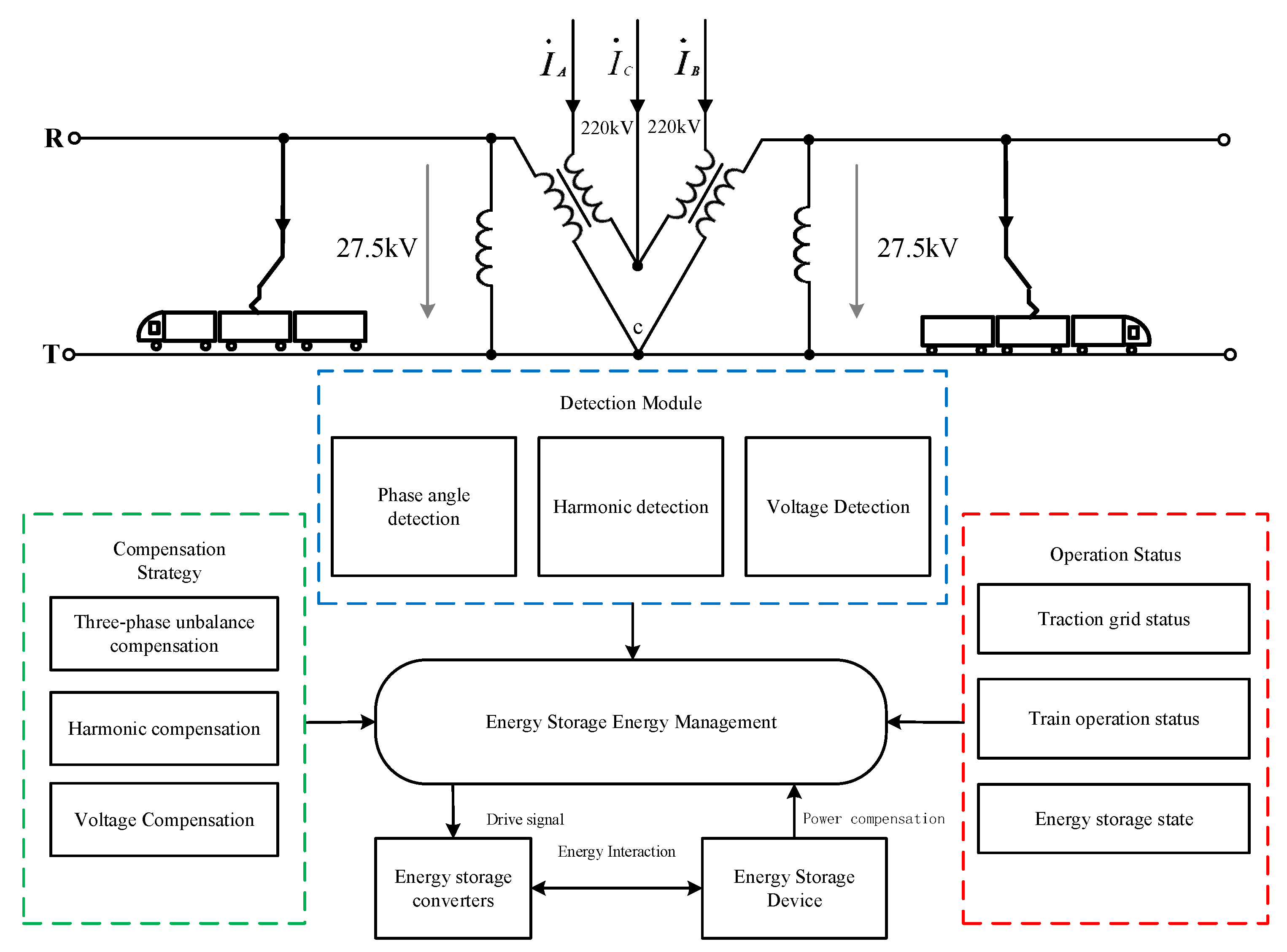
In summary, it can be seen that the power quality problem faced by rail transit is mainly reflected in the traction substation’s disturbance to the power grid. Energy storage equipment can achieve comprehensive power quality management of traction substations by adopting appropriate compensation strategies under the constraints of the rail transit operation state. The block diagram of the energy storage structure and comprehensive governance for rail transportation is shown in
Figure 31.
4.2. Control Strategy for Power Conversion System in Rail Transit
The stable DC voltage with low ripple content needs to be provided on its DC side; for the PCS to achieve the desired compensation effect, the actual compensation current of both phases should be able to quickly and accurately track the reference current command value. The mainstream method mainly adopts a dual closed-loop voltage and current control strategy. The voltage outer loop is used to establish a stable DC side voltage and provide the current inner loop reference current; the current inner loop is used to track and control the real-time output current of the converter [
37,
38,
39,
40,
41,
42,
43,
44].
The commonly used PI control is simple and easy to implement, but there are specific tracking errors and secondary ripple problems. However, there are specific tracking errors and secondary ripple problems. Adding a filter on the DC side is a standard method to suppress the second ripple. The third harmonic in the current reference signal can be avoided by pre-separating the DC component of the voltage outer loop input signal. The filter will cause delay and hysteresis of the signal. In the presence of significant disturbances, the conventional PI controller will appear to have a significant overshoot, for which the variable structure PI controller is widely utilized. The parameters in the variable parameter PI controller are designed as a function of the voltage error correlation, and the conventional PI controller is used in the case of small perturbations. In the case of large perturbations, the variable structure controller is used to improve the response performance. The block diagram of DC outer loop control is shown as
Figure 32.
The current inner loop tracking control performance directly affects the control effect of energy storage. The conventional control strategy is to obtain the current reference value by multiplying the current inner loop command value obtained from the voltage outer loop with the AC voltage phase.
This control strategy is limited by the method of tracking the current. The hysteresis loop current comparison method is mainly used in early theoretical studies due to its fast response and unconditional stability advantages. Still, there are tracking errors during operation, and it is also more sensitive to system parameter changes. The repetitive prediction-based differential beat-free control method can effectively correct the periodic tracking error and achieve smooth current tracking. Still, the need to calculate multiple modulation periods leads to a reduced tracking speed. The direct fuzzy tracking control method has the disadvantages of more robustness and low influence factors by nonlinear disturbances. The controller is based on logic implementation, which gives the control method better control adaptability, but improving the tracking performance needs to increase the complexity of the controller significantly. The PI control method based on fuzzy recursion realizes the adaptive adjustment of the PI controller, and the method can realize the current tracking for various operating conditions. The dual hysteresis loop control method combines the rapidity of the hysteresis loop comparative tracking control method and the steady-state non-differentiation of the recursive integral method, which can effectively compensate for the significant tracking error of the hysteresis loop control and the long adjustment time of the recursive integral method and realize the complementary advantages of the two methods. The block diagram of AC inner loop control is shown as
Figure 33.
4.3. Control Strategy for Energy Storage Management in Rail Transit
Rail transportation is a complex system, and the working state of energy storage is affected by many factors. According to different power allocation methods, the existing energy storage management strategies can be divided into voltage threshold control strategy, filtering algorithm control strategy, fuzzy logic control strategy, and model predictive control strategy [
65,
66,
67,
68,
69,
70,
71,
72].
The voltage threshold control strategy is often used in DC traction systems. This control strategy is mainly used to divide the operating state of the energy storage system into several nonlinear functions by setting several voltage thresholds such as
Figure 34. The control strategy can strongly suppress voltage fluctuations because the energy storage operating state is set to switch with voltage changes. The dynamic threshold-based control strategy is widely adopted to improve energy utilization further and extend the energy storage life.
The filter control strategy is now widely used in the energy field, mainly decoupling the high-frequency component of the target power from the low- and medium-frequency components through a filter to provide a power reference value for the energy storage system. The filter control is simple in structure and easy to implement. For the hybrid energy storage system of the electrified railroad, the first-order low-pass filtering algorithm is usually used for the power distribution between the supercapacitor and the battery to utilize regenerative braking energy efficiently. The low-pass filter has a response lag phenomenon, for which the Kalman filter, Fourier analysis, wavelet transform, and other spectral analysis means are also widely used.
The fuzzy control strategy Is an intelligent control method based on fuzzy set theory, fuzzy linguistic variables, and fuzzy logic reasoning such as
Figure 35. Its most prominent feature is that no clear relationship between input and output quantities needs to be established, which is very suitable for energy management of such complex systems as rail transportation. The fuzzy control inputs are generally the measured values of traction load power, energy storage system charge state, etc., and the outputs are the hybrid energy storage system charge and discharge thresholds or energy storage system output power reference values. The development of fuzzy rules is the key, but the fuzzy logic rule-based control method is more expert-dependent, and it is not easy to achieve optimal control. The control accuracy and dynamic quality cannot be achieved at the same time.
Model predictive control is a model-based closed-loop optimal control method whose core idea is a rolling time domain strategy such as
Figure 36. The method establishes appropriate constraints and objective functions to optimize the configuration of energy storage capacity and can obtain the control reference value of the energy storage system. Using model predictive control, the overall energy management of the rail system can be achieved by taking into account the traction characteristics model, train operation status, energy storage status, weather, and other factors. Model predictive control relies too much on an accurate circuit model, which is less robust and increases the computational burden of the controller with a rolling optimization process.
5. Conclusions
This paper summarizes the latest research results on energy storage in rail transit systems, matches the characteristics of energy storage technologies with the energy storage requirements of rail transit, and analyzes the operation of energy storage systems in different scenarios. The adaptability of batteries, supercapacitors, and flywheels as energy storage systems for rail transportation is summarized and compared. The topologies and integration methods of various energy storage systems are studied. The control strategies under various control in rail transportation are summarized and proposed.
The following conclusions are drawn by comparing the advantages and shortcomings of existing studies.
(1) The hybrid energy storage system has the characteristics of both high energy density and high power density. It can respond quickly, delay the decay of energy storage element life and reduce the investment cost to a certain extent when facing the complex working conditions of the electrified railroad power supply system.
(2) The energy storage converter system with a two-stage converter with a DC isolation circuit is suitable for the high-power working environment of rail transportation. The high reliability and easy expansion of the integrated structure of energy storage with modular common DC bus enable it to meet the plug-and-play of energy storage devices in the electrified railroad power supply system, whose cooperative control, loop current suppression, efficiency enhancement, and capacity optimization are the focus of subsequent research.
(3) Access to an energy storage system can effectively improve the power quality problem of the traction power supply system, and its compensation degree is positively related to the charging and discharging power of the energy storage device.
Energy storage technology has significant value and broad application prospects in rail transportation, but it still faces many technical difficulties and challenges in engineering practice.
(1) The energy storage system’s response speed and power tracking capability. High-speed trains run at high speeds and generate many load fluctuations quickly. For the control system in rail transportation, it needs to improve the control accuracy by shortening the sampling period and control interval, so the control model needs to have better dynamic characteristics to adapt to the fast-changing fluctuating load; for the energy storage medium, it needs to have stronger power tracking ability, so it needs to optimize the mixed matching scheme, capacity configuration method, and energy management strategy of the energy storage medium to improve the regenerative braking energy utilization efficiency under different power scenarios. The regenerative braking energy utilization efficiency under different power scenarios.
(2) Energy storage media and variable current device life loss. Energy storage media and variable current device investment in the total investment in energy storage systems occupy a dominant position. Still, in actual operation, there are different degrees of life loss for both. For energy storage media, long-term high frequency and high depth of charge and discharge will lead to reduced service life, especially in the electrochemical energy storage media. To increase the useful life of energy storage, energy management strategies need to be designed to limit the frequency of charging and discharging, thereby extending the service life. For variable current devices, frequent switching of traction power supply system conditions and drastic power fluctuations make the operating environment of power electronics devices harsher and increase the possibility of failure and need to improve system reliability by optimizing equipment selection and increasing redundancy configuration.
(3) Energy storage system life cycle economic benefits. At present, the high initial investment cost of the energy storage system in rail transportation limits its large-scale promotion, so it is especially important to improve the whole life cycle economic benefits of the energy storage system. On the one hand, it is necessary to improve the utilization efficiency of energy storage devices as much as possible, and reduce the energy storage by reasonably optimizing the capacity configuration model of the energy storage system and effective energy management scheme; on the other hand, it is necessary to clarify the revenue model of the energy storage system in rail transportation and establish a quantitative model to measure the revenue of energy storage system in terms of energy saving and improving power quality. When conditions allow, the energy storage system in rail transit needs to participate in the grid’s peak and frequency regulation dispatch to generate additional revenue and enhance the overall economic benefits of the rail transit system.


