Article

Potential of Load Shifting in a Parking Garage with Electric Vehicle Chargers, Local Energy Production and Storage

Division of Electricity, Department of Electrical Engineering, Uppsala University, Box 65, 751-03 Uppsala, Sweden
*
Author to whom correspondence should be addressed.
World Electr. Veh. J. 2022, 13(9), 166; https://doi.org/10.3390/wevj13090166
Submission received: 22 July 2022 / Revised: 9 August 2022 / Accepted: 25 August 2022 / Published: 1 September 2022

Abstract

:
The electrification of the transport sector is of crucial importance for a successful transition to a fossil-free society. However, the electricity grid constitutes a bottleneck. This article provides a case study based on a real-world parking garage with a smart grid infrastructure, called Dansmästaren. The analysis shows how renewable energy sources, energy storage technologies, and smart charging of electric vehicles can smooth out the load curve of the parking garage and relieve the electric grid during peak hours. Dansmästaren is located in Uppsala, Sweden, and equipped with 60 charging points for electric vehicles, a PV system, and a battery storage system. The study utilizes an energy flow model to show the potential of a realistically dimensioned smart energy system, that can benefit the parking facility in itself and the local distribution grid in a city, Uppsala, with grid capacity challenges. The results suggest that the parking garage demand on the local grid can be significantly lowered by smarter control of its relatively small battery energy storage. Moreover, further smart control strategies can decrease demand up to 60% during high load hours while still guaranteeing fully charged vehicles at departure in near future scenarios. The study also shows that peak shaving strategies can lower the maximum peaks by up to 79%. A better understanding of the potential of public infrastructures for electric vehicle charging helps to increase knowledge on how they can contribute to more sustainable cities and a fossil-free society.

1. Introduction

The transport sector is one of several sectors driving electrification as an important part of the transition to a fossil-free society. A lack of capacity in the electric distribution grid and an increasing penetration of non-dispatchable electricity generation are two challenges that threaten to slow down the transition to a more sustainable energy system. Moreover, the increasing use of electric vehicles (EVs) impacts demand peaks, reduces reserve margins, and increases electricity prices [1]. The transition to a fossil-free transport sector is also dependent on the charging infrastructure being expanded at a similar rate as the increase of EVs on the market. The electricity production and distribution capacity will thus come to be of crucial importance for the successful electrification of the vehicle fleet. However, unlike national grid-scale solutions which can be challenging to rapidly implement, there are potential local solutions that may help flatten the electricity demand and that can free up grid capacity in high load hours. Among these are the integration of renewable energy sources, together with energy storage technologies, as well as user-focused strategies for demand side flexibility and load shifting.
Higher flexibility on the demand side implies moving consumption to hours of lower demand, thus making better use of the existing grid capacity or better matching the consumption of electricity with the production from renewable sources. In terms of charging infrastructure, this can be achieved through smart charging strategies in combination with local energy storage and electricity production.
Previous studies have examined how different technologies and policies interact with each other and affect transport emissions [2,3], and how to implement a larger electric vehicle fleet in the energy system [4,5]. The potential for load shifting, i.e., moving the demand from peak hours to off-peak hours of the day, through controlled charging is demonstrated to be high [6]. The load shifting potential of electric vehicles in energy systems has been extensively studied: models, as in [7], and smart charging schemes, e.g., [8,9], have been proposed. The coordination of renewables and energy storage systems to optimize EV charging scheduling and management have been widely studied. For example, a smart charging management system for EV fleets integrating photovoltaic (PV) electricity production and energy storage (ES) systems have been designed in [10]. A charging model for a public infrastructure with PV and ES systems, which takes into consideration the charging prices, was developed in [11].
At present, there is a need for research based on models and data that are realistic from a power system perspective, as well as a facility-, technology-, and a vehicle-owner perspective. Moreover, there is a need for studies with experimental verifications. Efficient data collection, investigation of technical possibilities and challenges with smart charging (among others V2G [12]), as well as tests and analyses of smart charging strategies in real environments [13] are examples of issues that need to be explored. Smart algorithms that can control the system power flows need to be investigated as in [14] while always keeping in mind the needs of the electric vehicle users, the car’s battery pack requirements and, at the same time, the support to the local grid. Moreover, the co-creation of research and collaboration between partners from academia, the private and public sectors is vital to understand the challenges of real implementation and identify potential solutions, as well as to produce research that can more effectively support and speed up the transition to a more sustainable energy system.
In Uppsala and other big cities in Sweden, it is the capacity of the electricity grid that constitutes the biggest bottleneck. In Uppsala, the Swedish TSO Svenska Kraftnät (SvK) is planning to increase the grid capacity starting in 2024 [15]. However, extending the grid is expensive. Thus, traditional grid reinforcements should be accompanied by smarter use of the resources available, making the grid as a whole more cost-effective. EV batteries and chargers can be part of the solution to this challenge because they can be used as flexible resources thanks to the implementation of smart charging strategies. In the best case, they might even reduce the need for grid expansion.
The idea of this paper is to provide research on a real-world example of smart charging infrastructure. Its main contribution is to provide a case study—based on an existing and newly built parking garage with an advanced electricity infrastructure—that shows how PV, battery ES, and smart charging of EVs can smooth out and reduce load peaks, hence, lower a parking garage impact and dependence on the grid. This is achieved by developing an energy flow model and simulating different scenarios, each one with a different goal. First of all, the aim is to describe the energy flow during operation without control strategies, i.e., the current situation at the car park. Secondly, the goal is to investigate the potential benefit of implementing smart charging strategies. In these new scenarios, the aim is to show when and how the smart charging strategy and the energy storage system reduce the high consumption loads at the parking garage, lowering the costs of the parking garage owner. Moreover, the goal is to show how to minimize the consumption of the garage during hours of peak demand for the Uppsala distribution grid, by being self-sufficient during hours of high demand.
Although there is much good research available on the potential for smart charging, there is a lot that happens between theory and practical implementation. There is a risk that research does not provide answers that are realistic for stakeholders and that research, therefore, is not efficiently disseminated into practice. Hence, there is a need for co-created research and research questions with non-academic stakeholders, and for the scientific community to get examples of realistic scenarios. Even for a city like Uppsala with high ambitions towards sustainability and for its municipality-owned parking garages, many other factors that are economical, practical, and regulatory in nature affect what is built in the end. A better understanding of the potential of this parking garage will help to increase knowledge on how a public infrastructure can contribute to a more sustainable city, as it enables an increased share of renewable energy sources in the production mix and wisely uses the electricity from the distribution grid.

1.1. Background

The Division of Electricity at Uppsala University (UU) and The foundation for collaboration between the universities in Uppsala, business and society (STUNS) have developed a collaboration with Uppsala Parkerings AB (UPAB). UPAB, owned by the municipality of Uppsala, operates a parking garage at Dansmästaren, also known as mobility house [16], a building that includes a parking garage, 133 student apartments, and one grocery store. UPAB, together with STUNS and UU, has developed Dansmästaren to be simultaneously a commercial parking garage and test bed for research. The collaboration began at an early stage and led the researchers to influence the building’s electrical infrastructure and measurement system. This enables Dansmästaren to be a flexible test bed where different energy storage technologies, electricity generation units, and different strategies for smart charging have an opportunity to be tested in a real environment for many years to come.
Today, the parking garage is equipped with a solar park (50 kW/62 kWP), 30 charging stations from Charge Amps, each of them having two 22 kW charging points, a Li-ion battery storage (60 kW/137 kWh), a comprehensive measurement system, and hardware and software for the development of a smart energy management system (EMS). More detailed information will be given in Section 2.
Dansmästaren was inaugurated in the fall of 2020 and preliminary data were collected for about one year of service, enabling the validation of the energy flow model which is presented in Section 2. The results are discussed in Section 3 and the limitations of the model are included in the article. The major findings and conclusions are summarized in Section 4.

2. Materials and Methods

The aim of the model here presented is to simulate the energy flow in the mobility house for one year and with hourly resolution. Given the fact that a hourly time step is chosen for the simulations, the data are referred to as energy rather than power or average power per hour.
The available energy at the mobility house is given by the production of the PV farm, the available energy in the battery energy storage system, and the energy delivered by the grid. The PV delivers energy directly to the car park and charges the ES, while the solar overproduction is sold to the utility grid. The use of PV and ES as energy supply to the mobility house is prioritized over the use of the energy coming from the grid. The available energy that can supply the car park is limited by the rating of the transformer.
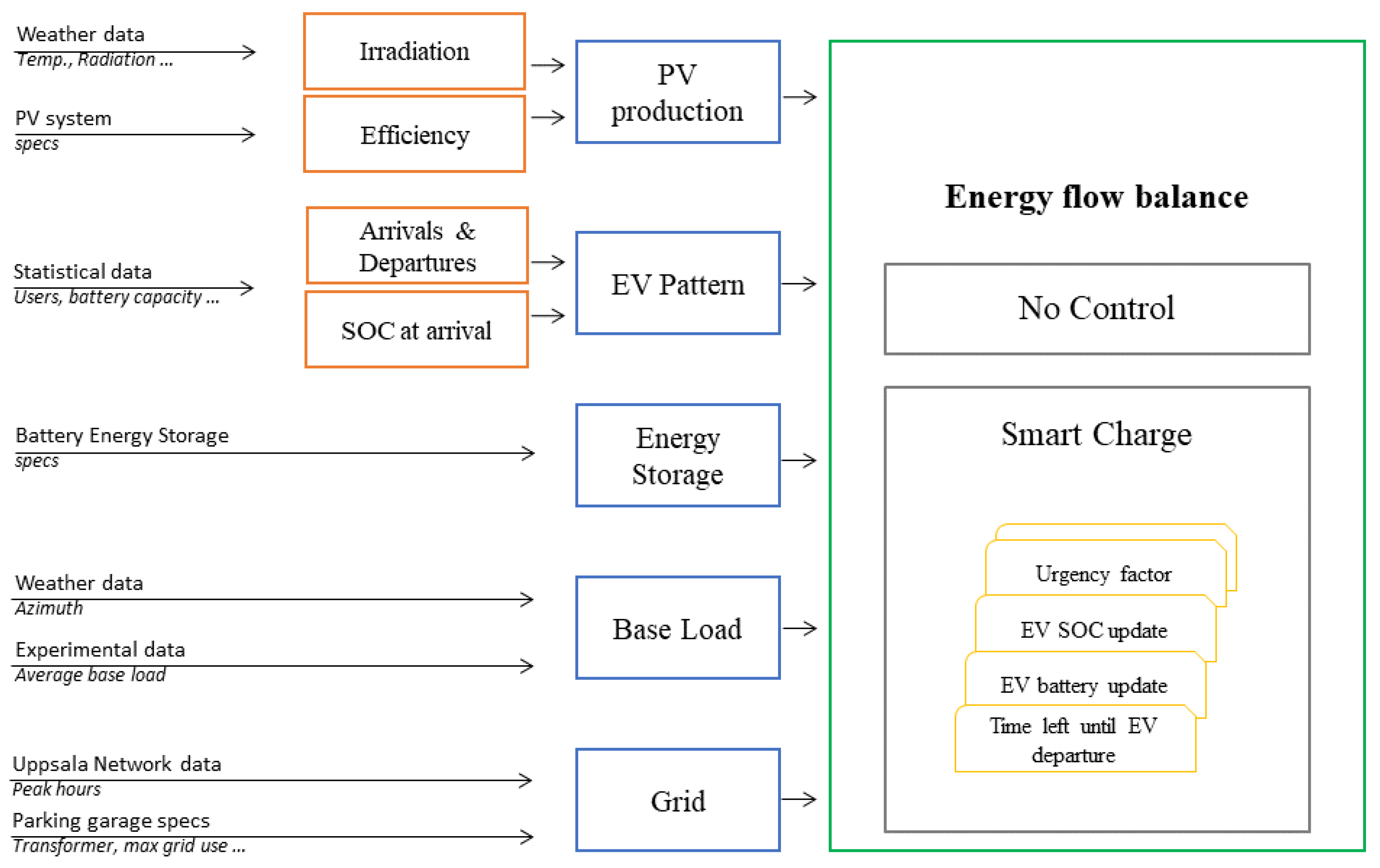
The model has been developed using the MATLAB calculation tool and it is organized in different blocks which are described below and schematically shown in Figure 1. The blue blocks are described in more detail in Section 2.1, Section 2.2, Section 2.3, Section 2.4 and Section 2.5 and they generate the inputs to the energy flow model. The model operates with smart charging of the EVs (Smart Charge) or without it (No Control). Each block is built on one or a series of MATLAB functions nested into each other.

2.1. PV Production

2.1.1. Set Up at the Mobility House

This block of code outputs the energy produced by the solar power plant installed on the roof of the parking garage. The PV plant is built by alternating rows of mono-facial solar panels [17] and bifacial panels [18]. The advantage of using bifacial panels is that they can absorb irradiation on the back side of the panel as well. The rated power of the plant is 50 kW (62 kWP), and consists of a total of 160 panels, 80 mono- and 80 bifacial panels. Each set of panels is connected to a 25-kW inverter and an energy meter. The latter, together with an ambient temperature and two irradiation sensors installed on Dansmästaren’s rooftop, will provide data to validate the PV model. For what concerns the irradiation sensors, one is installed measuring irradiation upwards and one downwards. The upward sensor measures the irradiation on the monocrystalline panels and the top side of the bifacial panels, while the sensor installed looking downwards measures the reflected irradiation hitting the bottom side of the bifacial panels. The PV data from SMA Solar Technology were collected from the web service called Sunny Portal [19].

2.1.2. Modeling

The model receives as input historical irradiation and temperature data downloaded from the Swedish Meteorological and Hydrological Institute (SMHI) website [20]. The coordinates are set to 59.838960 latitude and 17.639778 longitude. The missing data points have been replaced by linear interpolation of the existing data. The data, generated with SMHI’s models, have an error that is up to 42% for the direct normal irradiance from April to September 2021, the relevant time window for the validation. This value was provided by direct communication with SMHI meteorologists. In order to calculate the solar energy absorbed by the two sets of panels, the solar irradiation theory has been applied [21]. To calculate the efficiency of the panels, Equation (1) was used:
η = η r [ 1 β ( T c T r ) ]   ,  
where η is the efficiency of the solar panels, ηr is the efficiency of the panels at standard operating conditions, β is the cell temperature coefficient, Tc is the cell temperature, and Tr is the cell temperature at standard operating conditions [22]. ηr, β, and Tr are values reported on the panels’ data sheets [17,18], while Tc is calculated as:
T c = T a + G T ( T c , N O T C T a , N O T C G T , N O T C ) ( 1 η r )   ,  
where Ta is the ambient temperature, GT is the solar irradiation striking the solar panels, Tc,NOTC is the nominal operating cell temperature, Ta,NOTC (20°) is the nominal operating ambient temperature, and GT,NOTC is the nominal operating irradiance (800 W/m2).
η differs between the mono- and bifacial panels, hence, the PV efficiency of the entire PV plant is calculated as in Equation (3):
P V p = G T ( η m A m   + η b A b   )   ,  
where A is the surface area covered by the cells of the solar panels, and the subscription m and b refer to the mono- and bifacial panels respectively.
Using a constant inverter efficiency from the datasheets, the solar energy production was then calculated for the entire plant. This energy is available to balance the consumption of the parking garage, e.g., by charging EVs and the ES, and the excess is sold to the grid.

2.2. Energy Storage (ES)

2.2.1. Set Up at the Mobility House

The parking garage has a dedicated technical room where several power and energy storage systems can be installed. So far, a lithium-ion battery energy storage system has been connected and it is generically referred to as ES throughout the article. It consists of two battery racks of 9 modules each for a total capacity of 137 kWh (see Figure 2). The modularity makes this system suitable for scaling it up in the future. Each rack is connected to a battery management system and the inverters allow a charge/discharge limit of 60 kW in total. Safety features are currently being integrated into the system and the ES is not yet in operation.

2.2.2. Modeling

Within the model, the ES can be used to store solar energy and to lower the energy consumption from the grid during peak hours, contributing to peak shaving. During the simulations, a function updates the state of charge (SOC) of the energy storage depending on the charge or discharge during the previous time step. Moreover, the degradation of the batteries is taken into consideration, and it is based on the number of cycles of charge-discharge. The capacity fade is calculated using Equation (4) [23].
B c , t = B c , t 1 ( 1 ( 1 d r a t e )   N c ,   t 1   N c , l i f e )   ,  
where Bc,t is the battery capacity at a given time step of the simulation; Bc,t−1 is the energy storage capacity at the previous time step, drate is the degradation rate, assumed to be 70%; Nc is the number of cycles (or charging fraction) at the previous time step; and Nc,life is the lifetime of the batteries, set to 2000 cycles.

2.3. Electric Vehicles

2.3.1. Set Up at the Mobility House

The parking garage was inaugurated in the fall of 2020, during the COVID-19 pandemic. This influenced the number of vehicles parking at the garage and the EVs’ charging patterns. In 2021, the garage had 32 charging points intended for EV owners living in the residential area of Rosendal, some stations for short-time parking typically used by EV owners working in the area or visitors, and some charging stations for food delivery service cars. At the moment, the cars start to charge as soon as they are connected to the charging point, while smart charging will be implemented in the future. The data available on EV charging sessions at the mobility house were collected during 2021 and were supplied by the charging station manufacturer, ChargeAmps. The first months of data have been discarded because the number of EVs parking at the garage was negligible: the data collected consist of a few charging sessions. From May onwards, the data become more interesting to analyze, even though the number of cars parked daily is very limited, up to a maximum of 8 cars parking at the same time during evening charging sessions.

2.3.2. Modeling of EV Patterns

The block which models the EV charging patterns is built on different MATLAB functions. To represent reality in the best possible way, some hypotheses based on statistical data were made (Table 1). Note that the rating of the charging point has been given in Section 1.1 as 22 kW, but the power delivered by the charging point to the car was assumed to be 11 kW. The reason why this value was chosen is explained in Section 3.1.2.
The EVs’ consumption changes during the year, e.g., due to temperature differences and traffic intensity. Those fluctuations are taken into account and the EV profiles experience a variation during the simulated year. Moreover, the time of arrival and departure of each car is estimated depending on the user type: EVs owned by people living in the residential area of Rosendal and working during the day (charging during the night), EVs owned by residents working during the night (charging during the day), and EVs owned by people visiting or working in the area, hence, charging during the day. Statistical data on new registrations of EVs [24] and energy consumption of EVs [25] has been collected and analyzed to make those assumptions as close as possible to reality and to make predictions for the years to come. A reasonable future scenario identified for this study is when 60 cars a day will access the car park. In this case, we assume that 20 EV owners visiting or working in the area will park at Dansmästaren, that 34 residents will charge at night and 6 residents during the day (Table 2).
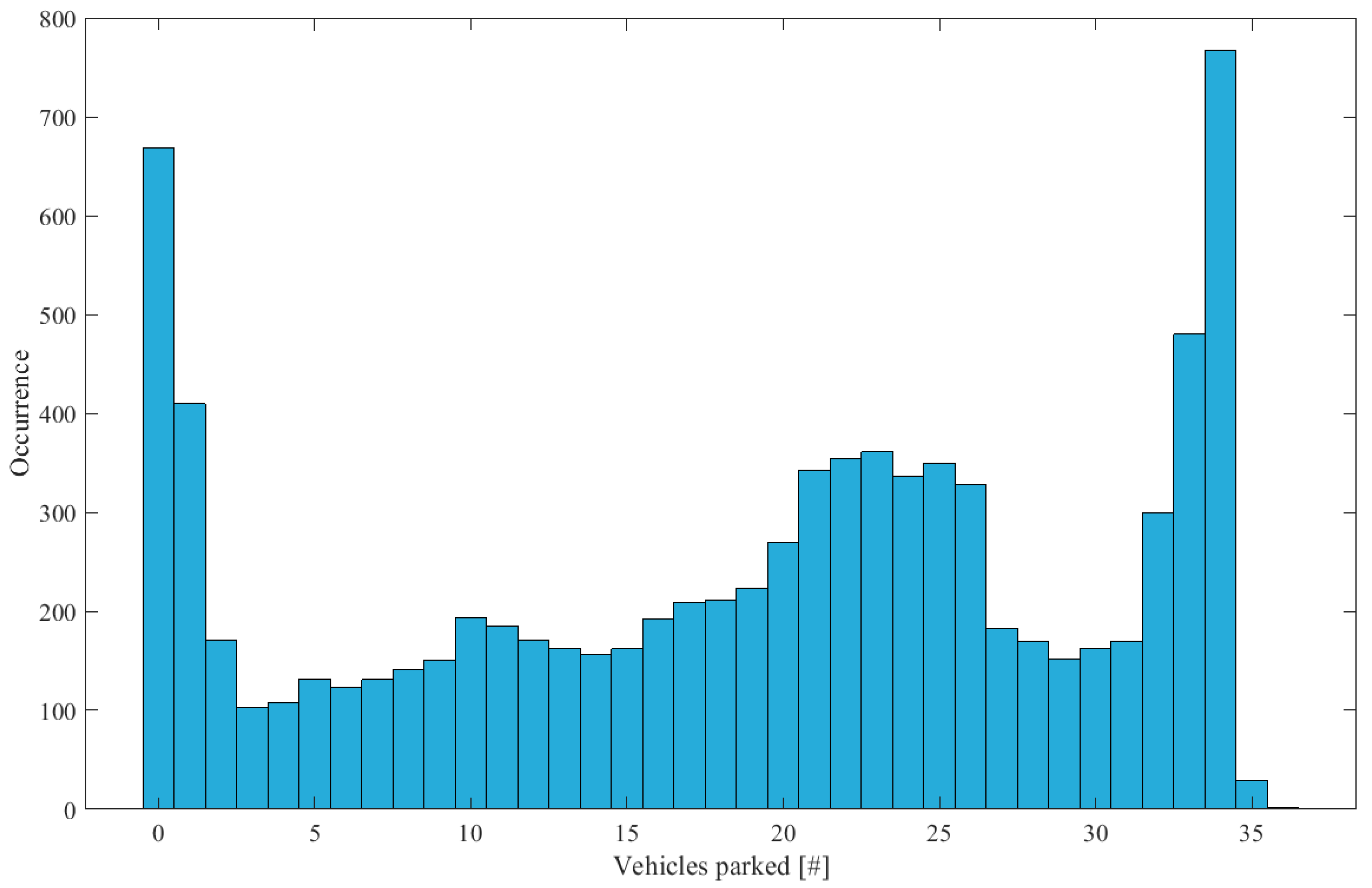
The vehicle parking simultaneously at the garage changes at every simulation because of the degree of randomness given by the variance applied to the arrival and departure times. An example is illustrated in Figure 3, which shows the occurrence of EVs parking simultaneously during one year.

2.3.3. Modeling of EVs Smart Charge

The simulations run in two different modes. The first mode allows the EVs to charge at maximum power as they arrive and plug in their cars to the charging point (so-called, No Control strategy). The second mode, called Smart Charge, is based on a priority charging strategy.
The No Control strategy reflects what happens at the mobility house nowadays: the cars plug in and start charging directly. On the other hand, the Smart Charge strategy consists in defining an urgency factor (UF) that is used to rank which EV charging needs to be prioritized at each hourly time step. In particular, the EV pattern block outputs a three-dimensional tensor, that for every time step and every new EV parking at the mobility house gives information on the maximum battery capacity of the EV, its updated SOC, the time steps left until departure, how many time steps are needed to reach the EV full charge (SOC = 100%), how much energy from the grid is available, and what the EV UF is. The UF is based on the time left until departure and the SOC of the vehicle at each time step. UF is calculated as the ratio between the minimum hours needed to get a fully charged EV (TSOC100%) and the time left until the vehicle departs (Tleft), as shown in Equation (5).
U F = T S O C 100 % T l e f t .
The higher the vehicle’s UF, the higher the priority given to that EV to charge. The Smart Charge algorithm is triggered every time the available energy from the grid, the PV, and the ES is not enough to charge simultaneously all EVs at the maximum possible rate. As will be discussed later, the available energy from the grid can be limited to a chosen value when running the Smart Charge algorithm: the grid maximum available energy (Eg,max) is a parameter that can be initialized in the Smart Charging algorithm and represents the chosen energy threshold that should not be exceeded at any time step.

2.4. Base Load

2.4.1. Set Up at the Mobility House

The sum of the peripheral loads consumed at the mobility house, independent from the EV charging, is here called base load (BL). The BL at the parking garage mainly consists of lighting the facility. A water pump, a ventilation system, a heated staircase, and elevators also contribute to the base load profile.

2.4.2. Modeling

To model this consumption curve, Equation (6) was developed. It shows the dependence of the BL on the average base load in 2021 (BLmean) and the angle of the sun above the horizon, α, where α = 90° − θ, with θ being the zenith angle.
B L = B L m e a n ( 1 2 + θ     θ min θ max θ min ) .
Currently, at Dansmästaren, the BLmean is 17.25 kWh approximately.

2.5. Electrical Grid

2.5.1. Set Up at the Mobility House and Challenges in Uppsala

From Dansmästaren’s perspective, the garage has a grid-connected three-phase transformer with a power rating of 345 kW. 276 kW are allocated for the EVs and the rest for peripheral loads.
From the city perspective, the two transmission system operator (TSO) substations connected to Uppsala’s distribution grid have a combined subscription limit of 293 MW. During 2015–2019 their limit was exceeded approximately 2% of the time during 112 days for a total of 802 h, 160 h per year approximately. Those peaks occurred during wintertime with 16 consecutive hours being the longest session, according to the results presented by the European project CoordiNet [26]. Data collected by SvK from the network area of Uppsala (UPP) for the time window 2018–2021 were used to find the 150 highest load hours per year in a more conservative scenario. Figure 4 shows where and when those load hours occurred, cumulating them over the four-year period. As illustrated in Figure 4, the majority of the high load hours take place in the afternoon between 4 p.m. and 6 p.m. Furthermore, the highest load hours occur mostly in December to February and during weekdays.

2.5.2. Modeling

As mentioned in Section 1, the energy flow model has multiple goals. The aim is to show (a) when and how the smart charge strategy and the ES contribute to shifting the load at Dansmästaren, and (b) how the mobility house can stress the grid the least during peak hours. From a modeling viewpoint, the consumption of the mobility house will be forced to decrease a few minutes before the critical time window when the peak occurs and start to slowly increase after it, to take into account a smoother transition during grid coupling and decoupling.
The former goal (a), focusing mainly on the parking garage owner’s perspective, is achieved by smoothing out the load curve and avoiding consumption peaks. Moreover, the contribution of the energy from the grid is limited to a certain threshold, Eg,max. The latter goal (b), focusing mainly on the city perspective, is achieved by reducing the contribution of the energy from the grid up to zero during peak hours. From Figure 4, it can be concluded that a smart control system, if statically modeled, should avoid charging the cars at least between 4 p.m. and 6 p.m. from December to February. This can reduce the contribution of Dansmästaren to grid peak load hours that violate the subscription limit. For ease, this interval will be set from January to December, i.e. the entire year, in the simulations.

2.6. Simulation Scenarios

Based on the goals set in Section 2.5.2, several scenarios have been simulated. Table 3 summarizes them, and Section 3 will present and discuss the results from each scenario.
Scenario 1.a reflects the current situation at Dansmästaren. Scenario 1.b shows what might happen once the ES will be operational. Scenarios 2.a and 2.b take into consideration the needs of UPAB to avoid energy peaks during the day. Scenarios 3.a and 3.b take into consideration the peak hours for the grid in Uppsala, aiming at running the garage in island mode between 4 and 6 p.m.
The current situation at the parking garage sees a limited number of EVs charging per day. In the future, the number of EVs on the market will increase, as well as the number of electric cars parked at Dansmästaren. Based on the new registrations of EVs in Uppsala County [27], 53% of EVs are hybrid and about 47% are electric. To simplify the analyses, we assume that in the future the hybrid vehicles will charge at a higher rate than today, but still keep a battery capacity smaller than that of battery electric vehicles.

3. Results and Discussion

This section presents results on the validation of the energy flow model (Section 3.1) and the scenarios summarized in Table 3 (Section 3.2).

3.1. Model Validation

Before simulating the scenarios, the validation of the model with the data gathered during the first months of operation of the parking garage has been conducted. The data available depends on when the systems have been connected and/or the data management system started to operate.

3.1.1. PV Production

The data used for the validation of the PV production at the mobility house span from 1 May (when the PV plant was fully operational) to 15 September 2021 (when the data were retrieved for the validation). The choice of this time interval for the validation is justified by the fact that the solar irradiation at Swedish latitudes is significant during the summer months. When modeling the PV production at Dansmästaren, we need to consider that the weather inputs come with an intrinsic error, as mentioned in Section 2.1.2.
Thanks to the irradiation sensor mounted looking downwards (more info at Section 2.1.1), the efficiency of the bottom part of the bifacial panels could be calculated. The results show increased efficiency of less than 2% for the bifacial panels compared with the mono-facial ones. This small increase in efficiency is caused by the small degree of reflectance of the surface where the panels are mounted, on the parking rooftop.
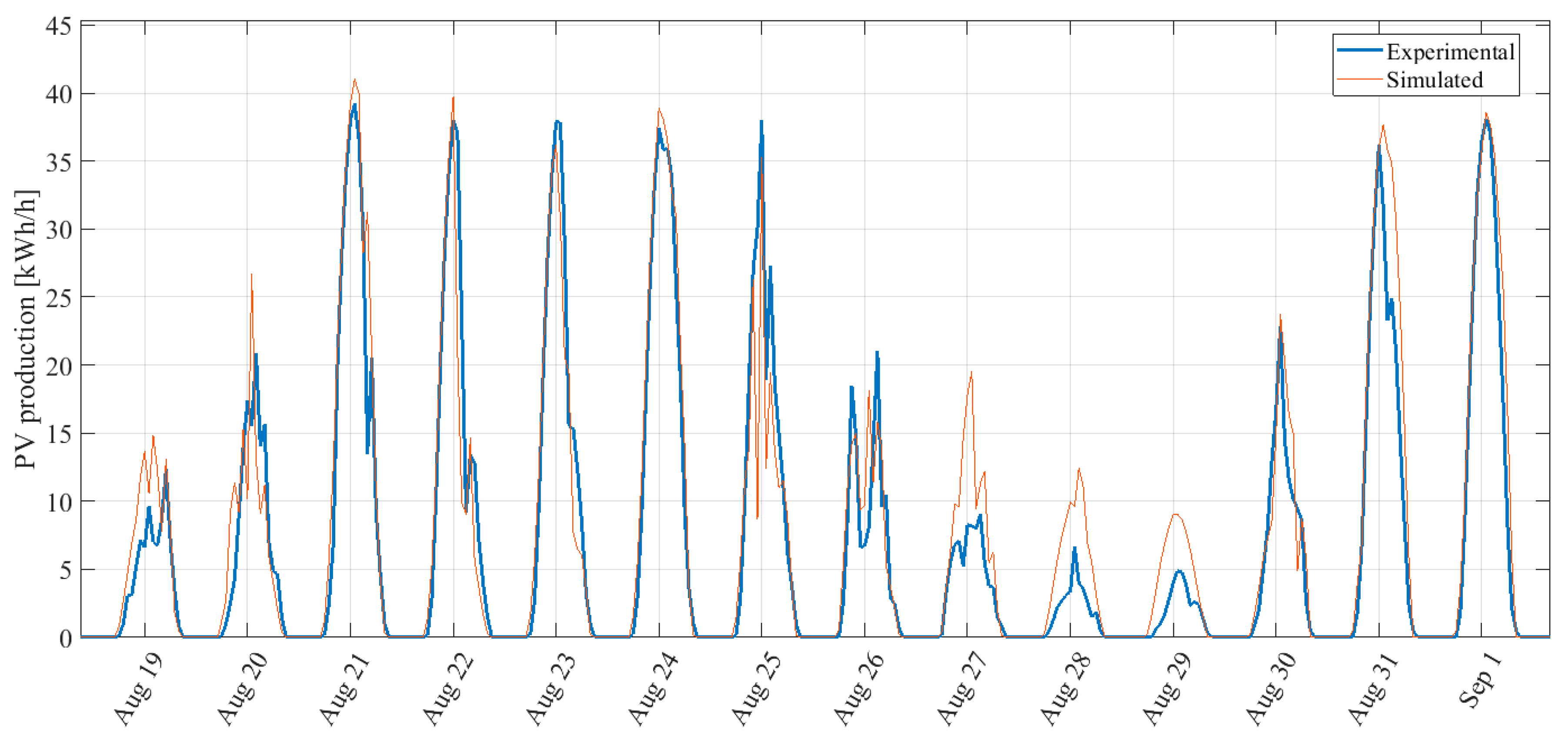
The measured PV production for the period from 1 May 2021 to 15 September 2021 is 33.5 MW while the simulated one is 35.7 MW. The normalized root mean square error (nRMSE) is calculated to be 11.3%, which is considered a satisfactory result for the months taken into consideration. Figure 5 shows a zoom in on the time series analyzed in order to illustrate the measured and the simulated profiles.
The energy flow model shows the potential impact of the mobility house during one generic year. For this reason, the weather input data used to calculate the PV production can be taken from historical data. The assumption is that, on a yearly basis, the PV production should be representative independently of what year the input data comes from. In order to make predictions for the years ahead, the forecast would not be available anyway. Furthermore, the PV production model will be useful when studying the potential of future parking garages which have not been built yet. Hence, specific PV data referring to a particular year are not required for this study. In conclusion, the development of a validated PV model would be useful when running simulations on upscaled PV installation for future infrastructures.
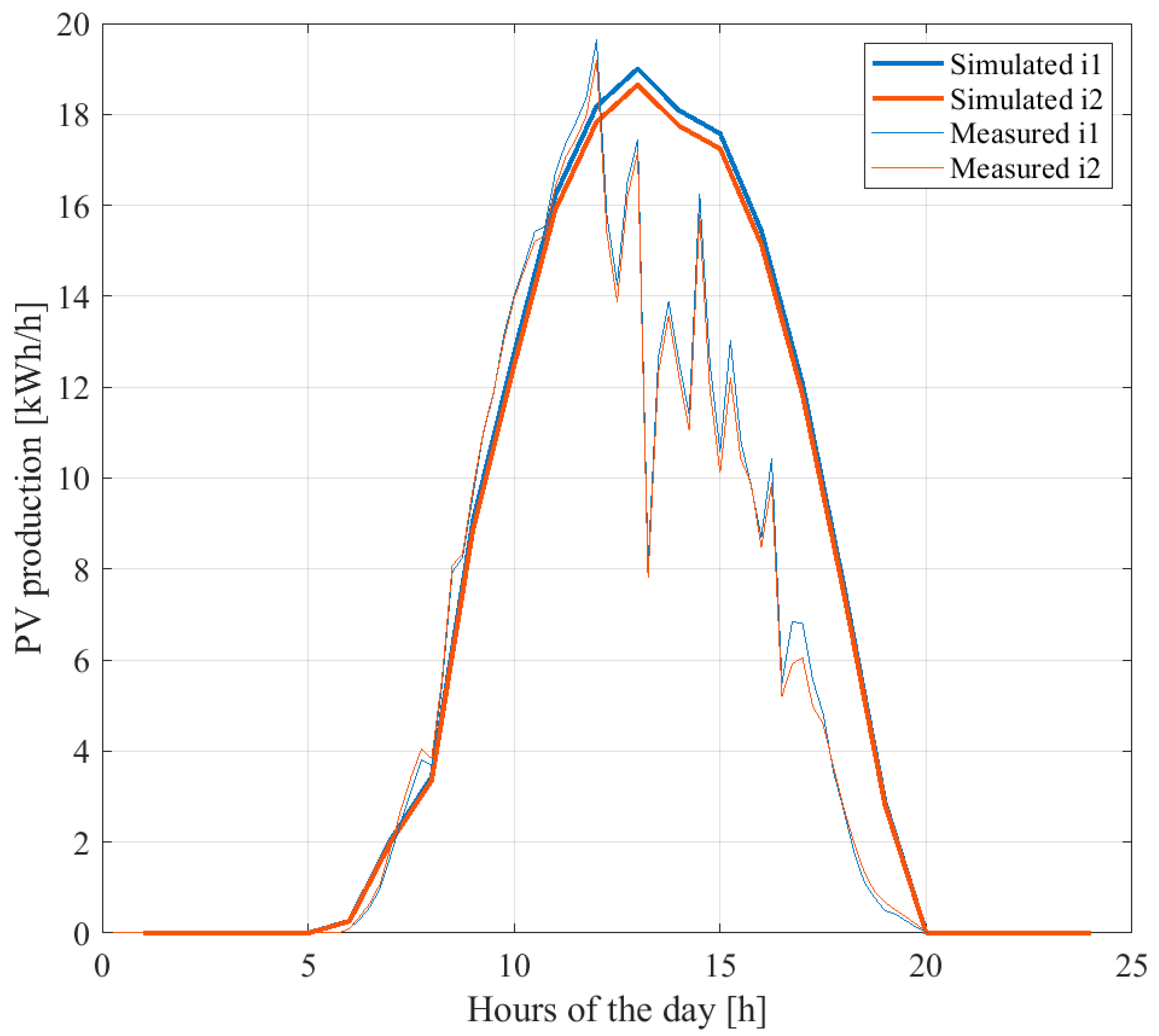
The solar energy that can be used at Dansmästaren, taking into consideration losses and inverter efficiencies, has been calculated and compared (Figure 6). Note that the model runs at hourly time steps and the variations shown in the measured data with 15-min resolution cannot be captured, as shown in Figure 6.

3.1.2. Electric Vehicles

The data collected from each charging station have been analyzed to draw conclusions on the charging pattern of the vehicles parking at the mobility house. As previously mentioned, the restrictions due to the COVID-19 pandemic influenced people’s behavior and this made the data more difficult to interpret. As an example, the recommendation of distance working discouraged car owners to go to work, and hence, to park and charge during the day. Additionally, many outdoor parking areas in the vicinity of the studied garage became free of charge during the pandemic, discouraging car owners to park at the mobility house. In other words, the goal of understanding from a few months of data representative EV charging patterns became more challenging than expected. A clear pattern was not even recognized during the weekends compared with the weekdays. For the reasons here presented, the validation of the EV charging pattern is very limited and more assumptions will be made when simulating future scenarios. The authors believe that the situation will change in the upcoming years and the data will be more relevant.
Another problem with the available data is the lack of information about the departure time of the cars, i.e., the smart charge strategies for load shifting cannot be implemented because it is not possible to calculate UF. What is known from the data collected at the parking garage is when EVs are plugged in for charging, i.e., when they arrive, but there are no sensors installed at the parking to provide information on their departures. A charging session terminates when (a) the car is fully charged or (b) when the car leaves the garage. In case (a), there is no information regarding the departure because the car could still be parked after reaching a full charge. However, we could estimate the energy consumption of the vehicle until a full charge. In case (b), we could estimate the departure time, but information regarding the car SOC at departure is not available. Anyhow, the EVs which behave as in (a) and (b) cannot be distinguished at the moment, and for this reason, no conclusion can be drawn.
Regarding the charging profiles presented in Table 2, an attempt was made to estimate the average arrival time of night chargers and day chargers together with the number of cars for each category accessing the car park daily. In general, the consumption curve due to the EV charging shows a large evening peak around 8 p.m. and two smaller peaks throughout the day: one early in the morning and another around midday. The results are summarized in Table 4 and used as input for the model. Unfortunately, it was not possible to draw any conclusion regarding the type of users (Residents, visitors), nor to find any clear EV pattern, but higher penetration of EVs and more measurements will allow this in the future.
The preliminary results that were obtained (Table 4) reflect what is found in the literature. Siddique et al. [28], for example, analyzed the charging patterns of EVs based on about 190,000 charging sessions from 821 charging stations in Illinois and they obtained hourly variations over a day for different categories of users (Figure 3 in [28]). Looking at the curves for paid parking, multifamily commercial, paid workplace, and retail, which represent the activities in Dansmästaren, hourly peaks are observed at 8 a.m. and 12 p.m. for paid parking; at 8 a.m., 6 p.m. and 8 p.m. for multifamily commercial; 8 a.m. for paid workplace; 4 p.m. for retail. The profiles in Table 4 resemble, to a certain extent, the charging peaks in [28]. Hence, the partial validation of the model seems reasonable.
By running the model with the input parameters of Table 4, Figure 7 was obtained. It shows the consumption at the parking garage based on simulations and measured data. The nRMSE between the curves is found to be 23.6% for December. The simulated data try to catch the evening peaks and show a pattern during the day, but hardly reflect the real charging behavior of the EV owners. The higher peaks registered in the evening are probably dependent on the food delivery cars. The assumptions on the charging rate, cars’ SOC, and battery capacity made in the simulations (Table 1) contribute to adding an intrinsic error to the simulated EV consumption curve.
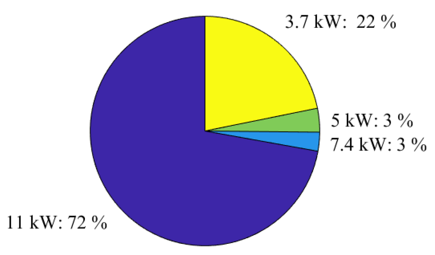
An interesting result that could be extrapolated from the data is the vehicles’ charging rate. The diagram illustrated in Figure 8 shows the rate of charge divided into four categories.
About 72% of the vehicles charging at Dansmästaren during 2021 charged at 11 kW, 3% at 7.4 kW, and 22% at about 3.7 kW. To keep the simulation as easy as possible, we will assume a conservative scenario where all the cars are electric and charge at 11 kW.

3.1.3. Base Load

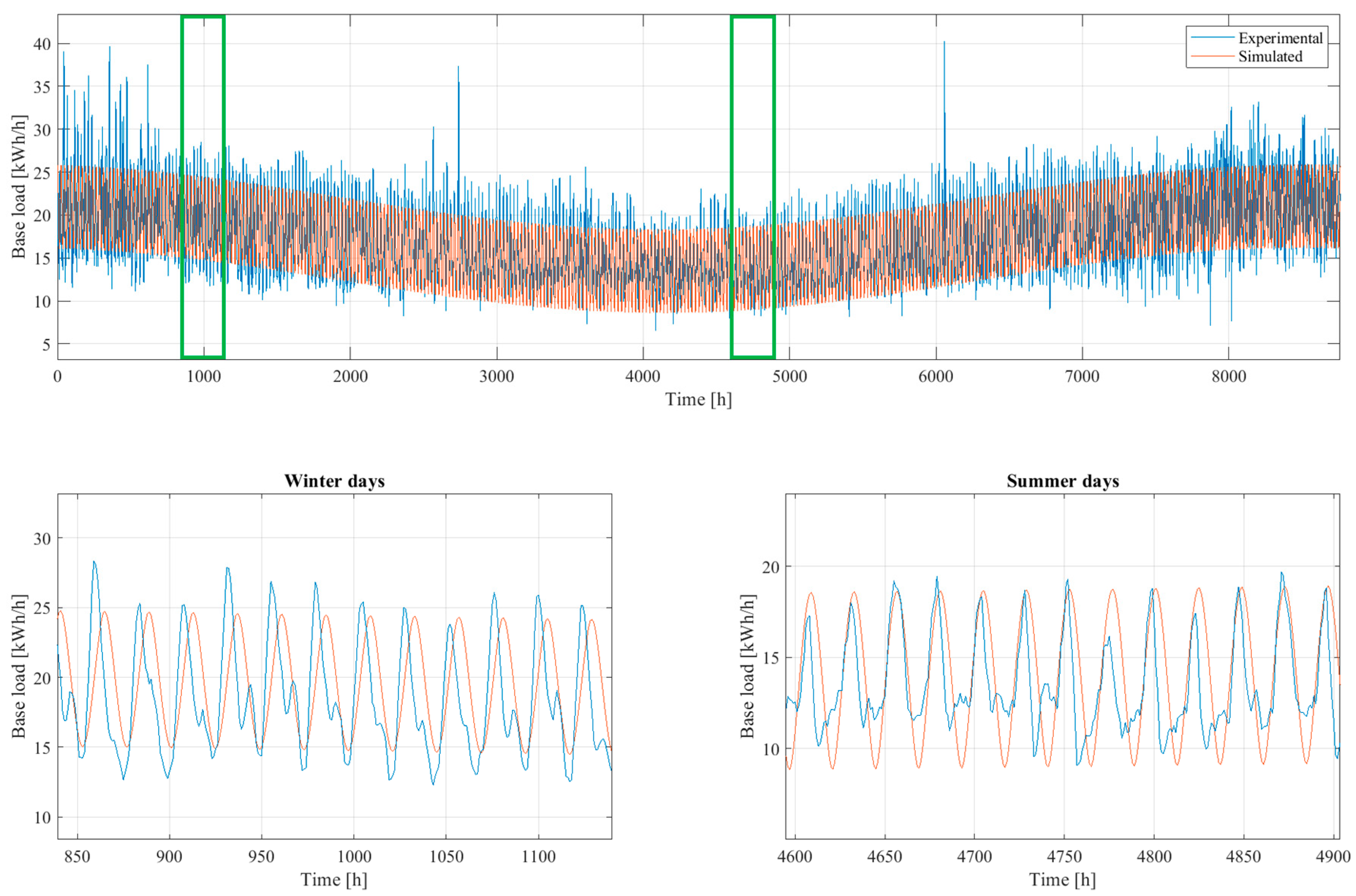
The data collected for this validation span from 1 January to 31 December 2021 and include all the load at the parking garage excluding the EV charging. The average base load measured at the mobility house during this period is about 17.25 kWh/h and the total energy is 151 MWh/h. The simulated average base load is kept to 17.25 kWh/h and the total base load calculated for 2021 is again 151 MWh/h, both results corresponding well to the measured values. However, the measured and simulated curves illustrated in Figure 9 have an R2 of 0.25.
Monthly variations of the base load are observed in the experimental data: the mean base load is higher during winter months and lower during summer months. As can be seen from Figure 9 (Summar days), the load has a plateau during the evenings of summer days, reflecting the weather conditions in Sweden: during long summer days, the lighting is off, and the load is lower.
Now that the base load and the charging patterns have been simulated, a comparison with measured data from 2021 can be made. The total consumption of Dansmästaren during one year was about 208 MWh, and the simulated one was 189 MWh.
Figure 10 shows a zoom in on the load curves for the same time interval as Figure 7.

3.2. Charging Scenarios

Once the model was set up, different energy flow scenarios were investigated. With reference to Table 3, six scenarios have been simulated and the results are presented and discussed below. Note that the current scenarios run using the charging profiles in Table 4 and the future scenarios use the charging pattern in Table 2. In the latter case, we assume that more EV owners visiting or working in the area will park at Dansmästaren (20 cars/day), that there will be 34 residents charging at night, and six residents charging during the day. As mentioned in Section 2.3.2, these values are based on statistical data applied to the district of Rosendal, in Uppsala, where Dansmästaren is located. Hence, the number of cars belonging to each category does not reflect what is currently happening at Dansmästaren. The EVs for food delivery are not considered in these simulations given that it was not possible to characterize their charging pattern and that the contract they have with UPAB might expire.

3.2.1. Scenario 1.a

The results presented here refer to the current scenario at Dansmästaren: The parking garage runs using electricity coming from the grid and the PV for in-house use. The excess solar energy is sold to the utility grid and the energy storage is not connected to the energy system yet.
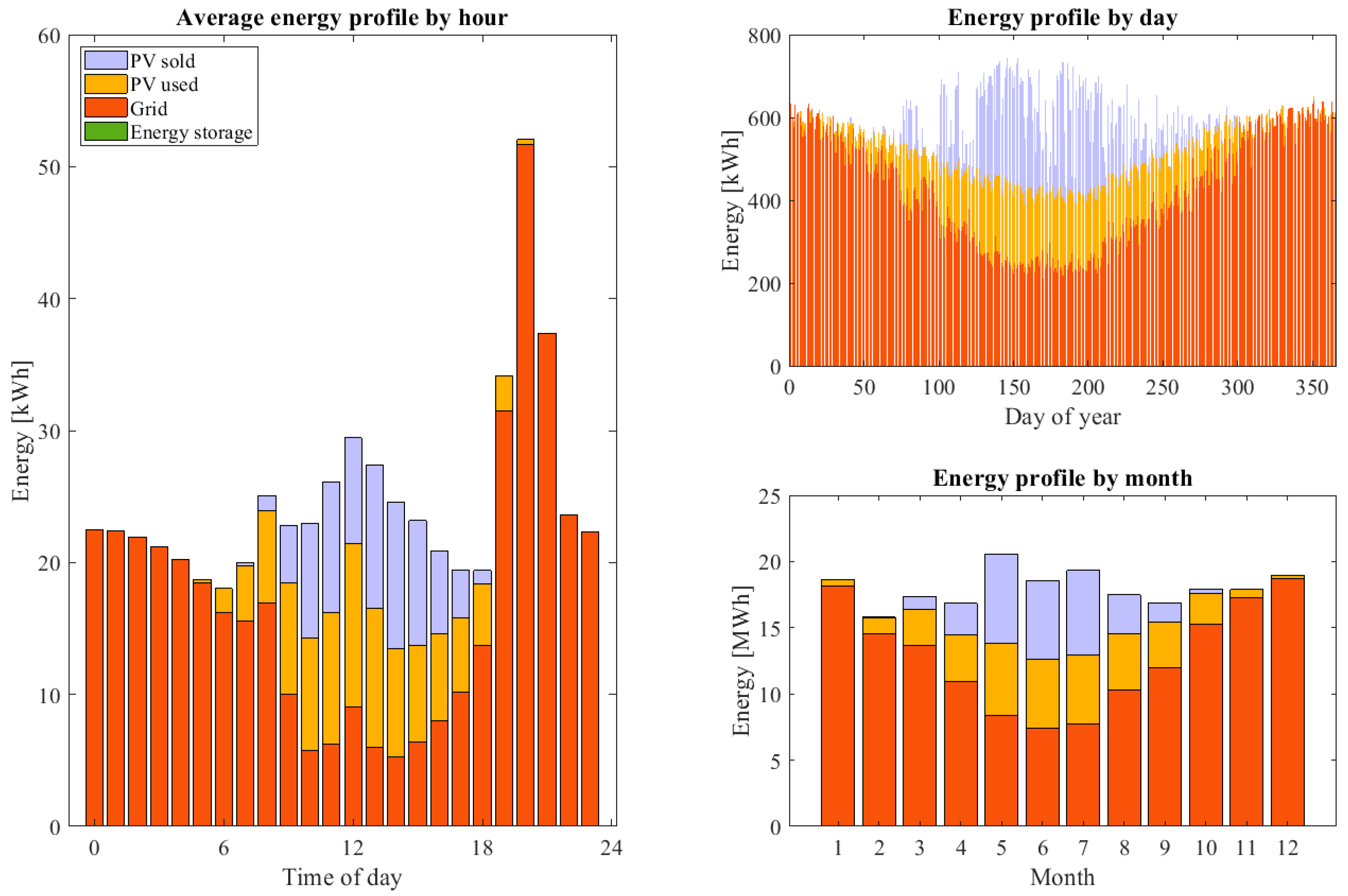
The results for scenario 1.a are summarized in Figure 11, which shows the average energy profile by hour, day, and month for this scenario. The PV sold represents the PV overproduction that could be sold to the utility grid; the PV used is the share of solar energy utilized in-house; the Grid is what the parking garage needs to buy from the utility grid; the Energy storage represents the contribution of the battery ES, that for scenario 1.a is of course zero, given that the ES is turned off. Figure 11 illustrates that on average the consumption is higher around 8 p.m. and during the winter months. In both cases, the contribution of the PV is not beneficial without a proper energy storage system.
The charging patterns of Table 4 were used for this simulation to be able to show the 8 p.m. peak, currently being registered at the mobility house, and to illustrate the benefit of using the ES, as described in Section 3.2.2 for Scenario 1.b.
As commented in Section 3.1, the EV changing input data to the model limits the accuracy of the results. To understand the magnitude of the error, new simulations were performed by changing the inputs of Table 4. The analysis of the EV charging data could lead, for example, to a reasonable assumption that one morning charger, four afternoon chargers, and seven night chargers would park at Dansmästaren daily, arriving at 9 a.m., 3 p.m., and 9 p.m. respectively. The results of the new simulation differ from the original one by 4% when comparing the highest grid peaks during the year, and by 1% when comparing the annual energy from the grid.

3.2.2. Scenario 1.b

This scenario differs from the previous one because it shows how the energy system would behave if the battery ES system were to be turned on at Dansmästaren. In this simulation, the ES is charged exclusively by solar energy. The contribution of the PV is used first in-house and what is left is used to charge the batteries. Given that the No Control strategy is active, it is more beneficial to charge the batteries with PV production, rather than charging via the grid at any time, which would mean charging during peak hours as well. However, charging the ES exclusively from PV might not be sustainable in the winter and on cloudy days.
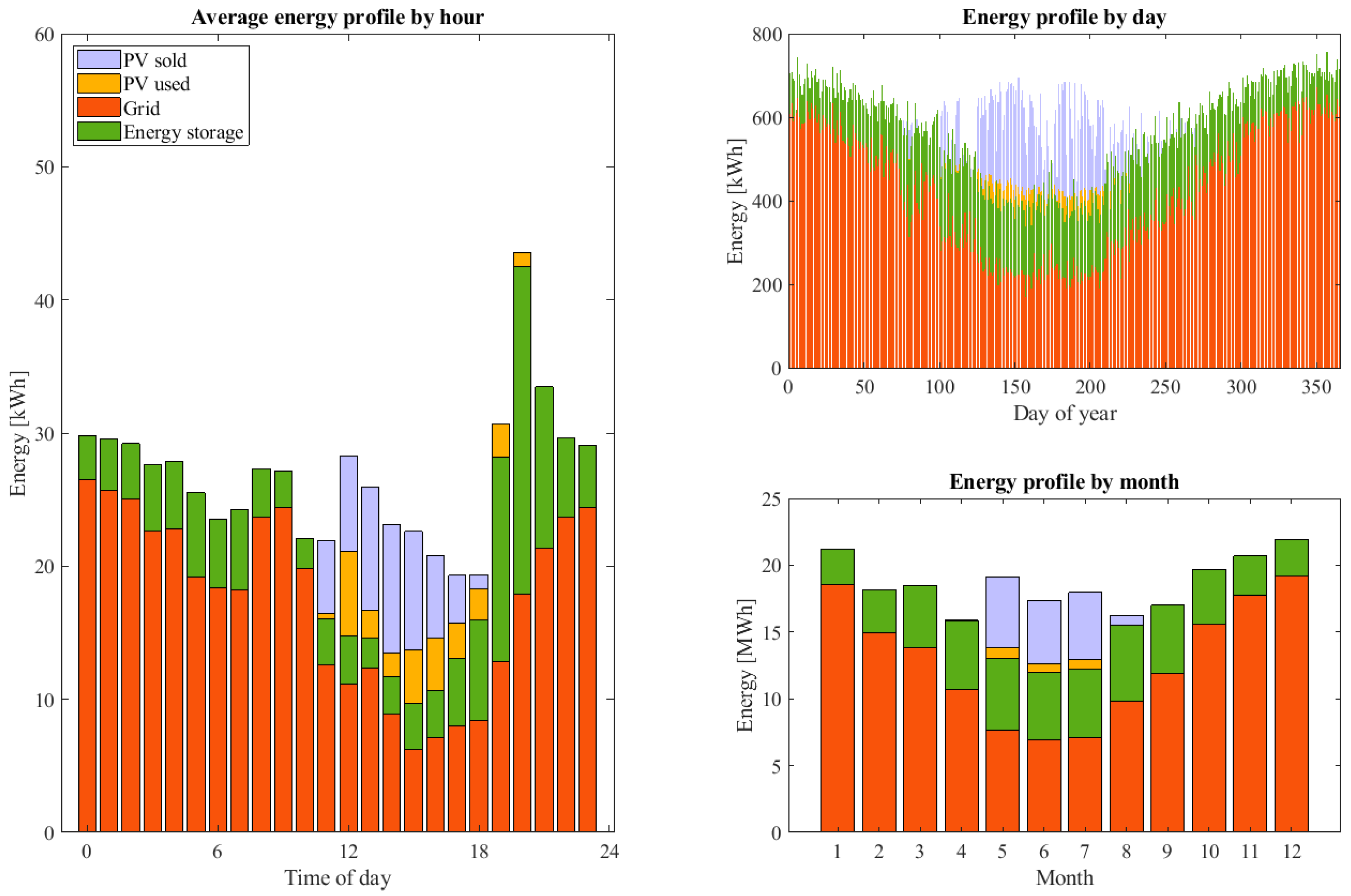
As shown in Figure 12, the 8 p.m. peak is reduced by approximately 27%. A similar reduction is seen also at 7 p.m. and 9 p.m. which are, on average, critical hours from an energy demand point of view at the mobility house. The total grid use during the year is reduced by 11% between scenarios 1.a and 1.b.

3.2.3. Scenario 2.a

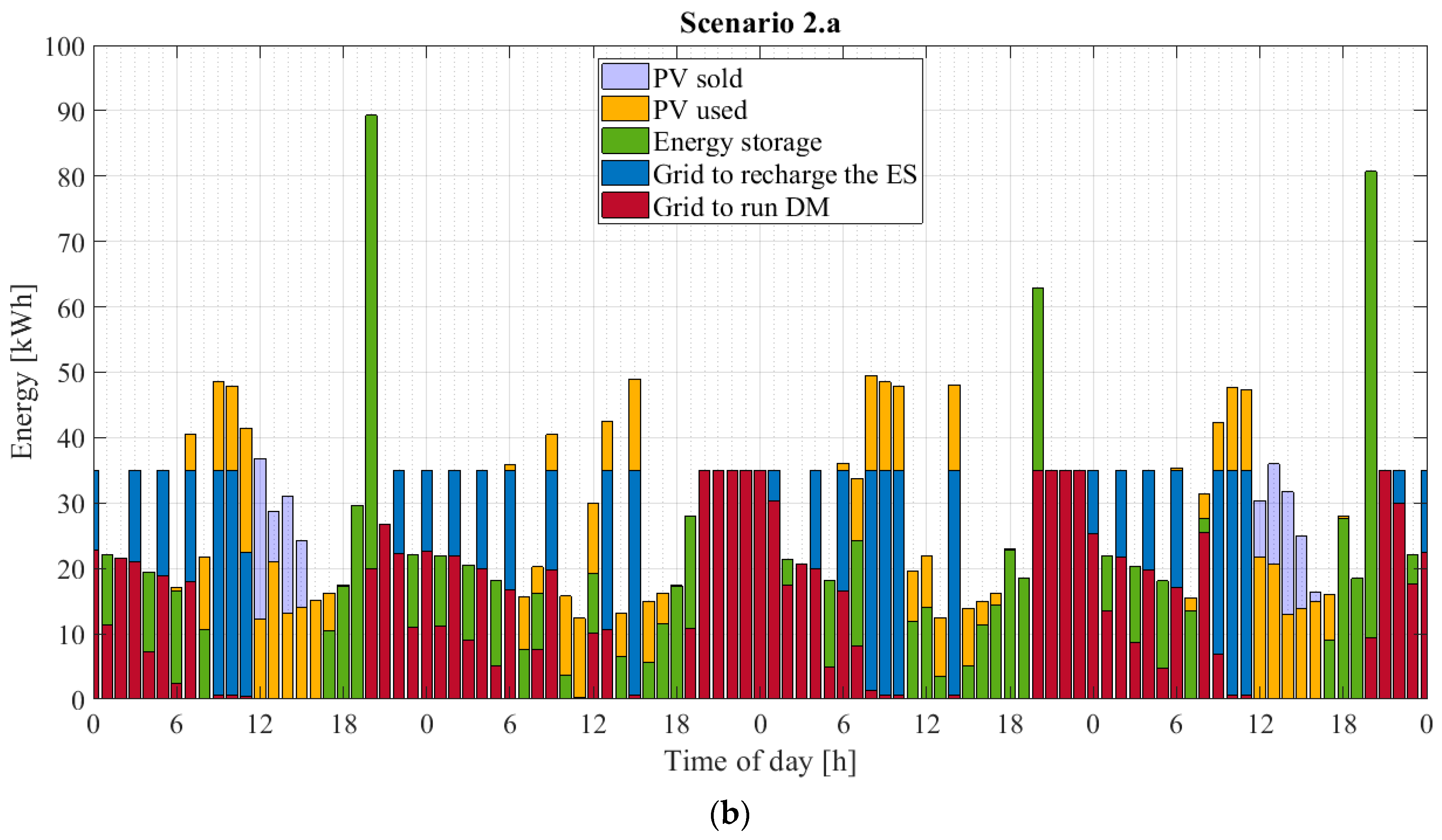
This scenario shows how the peak shaving at Dansmästaren could appear when the Smart Charge mode is activated in the simulation. The PV and the ES are operational and the cars are charged using a priority charging algorithm. For more details about the method, refer to Section 2.3.3. The ES is charged by the PV and—if that is not sufficient—by the grid. Moreover, Eg,max is set at 35 kWh, meaning that the model will try to keep the grid consumption below 35 kWh at every time step. This value was chosen so that the annual contribution of energy from the grid in scenarios 1.a and 2.a has the same value, even if the grid is additionally charging the ES in 2.a. Moreover, this value allows all the EVs to leave the parking garage with a fully charged battery pack.
Figure 13 shows that the peaks between 7 and 9 p.m. are shaved (compare with Figure 11) and that the energy storage contributes on average to the hourly energy supply.
By comparing the energy profiles by day and by month in Figure 11 and Figure 13, the difference is not remarkable from a grid consumption viewpoint: the ES is being charged by PV and grid. Hence, this result is expected on both daily and monthly averages. The total grid usage in scenario 2.a is similar to scenario 1.a, approximately 154 MWh, but is more evenly distributed on a daily basis.

3.2.4. Scenario 2.b

In this new scenario, we simulate what could potentially happen in the future, when more EVs will park at Dansmästaren. In Section 2.3.2, the modeling of the EV profiles has been explained and the values of Table 2 are used for scenario 2.b, when about 60 cars a day will access the car park.
In this scenario, Eg,max is set to 54 kW. This value was chosen because it limits the energy consumption from the grid and, at the same time, allows all the cars to have a fully charged battery pack at departure.
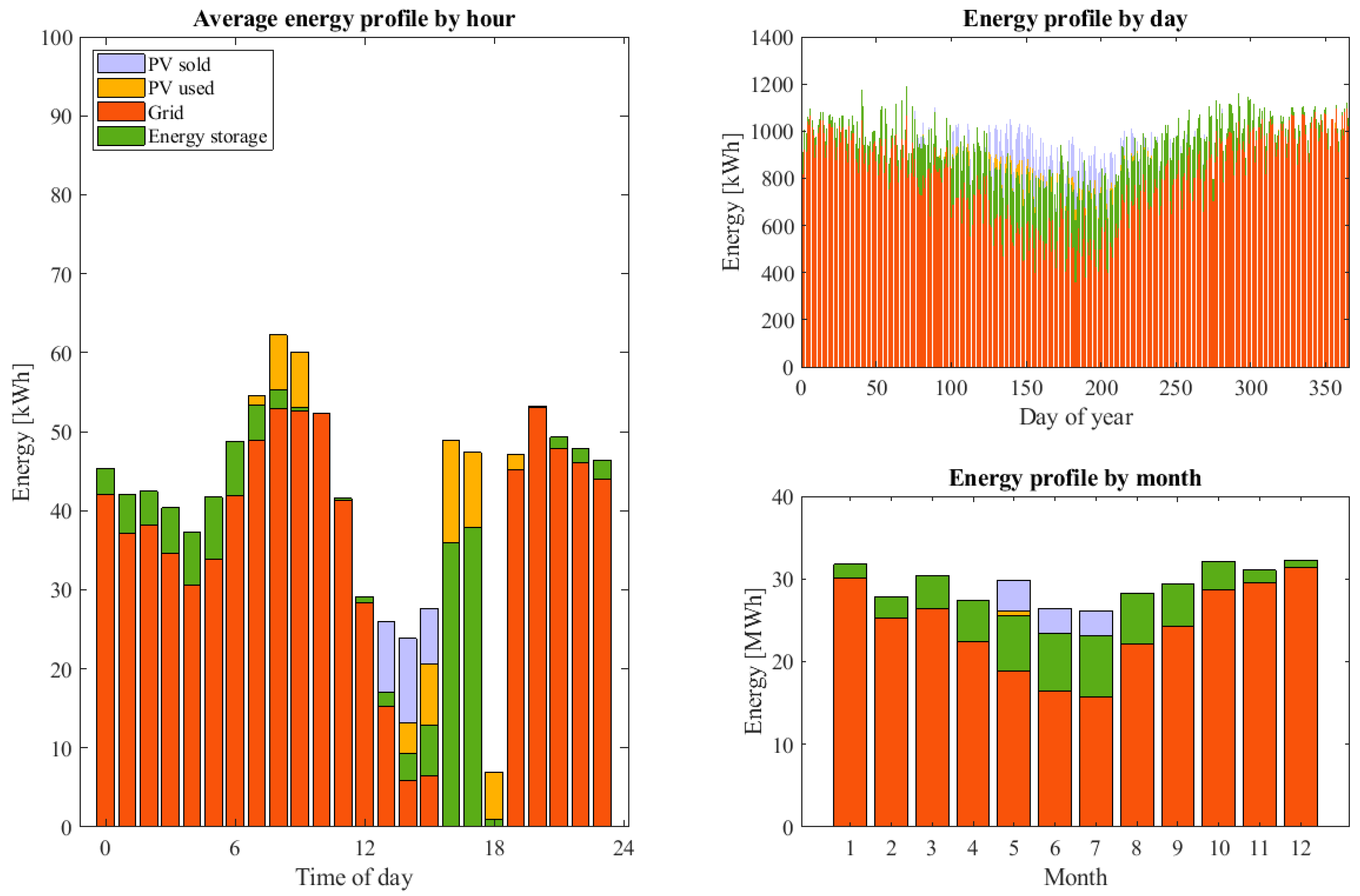
Comparing scenarios 1.a and 2.b (Figure 11 and Figure 14 respectively), the number of cars changing daily has increased by 52 units, but the annual grid used during the year doubled, reaching about 300 MWh.

3.2.5. Scenario 3.a

In this scenario, the goal is to keep the consumption curve of Dansmästaren uncorrelated with the load curve of the grid in Uppsala. In other words, the parking garage does not contribute to additional stress on the grid during peak hours by becoming self-sufficient. As previously discussed, the peak hours for the simulations are set to 4–6 p.m. and the consumption of the mobility house starts to decrease a few minutes before 4 p.m. and starts to increase after 6 p.m. The number of EVs charging at the parking garage is the same as in the current scenario to allow a comparison among 1.a, 1.b, 2.a, and 3.a.
In Figure 15, the average energy profile by hour shows that during peak hours (4–6 p.m.) the parking garage does not use any electricity from the grid. This results in slightly lower power consumption on a yearly basis compared to scenario 1.a and has no impact on the SOC of the vehicles, which leave the changing sessions with fully charged batteries. The average energy profile by hour in Figure 15 shows that the grid consumption does not exceed the set threshold of 35 kWh.

3.2.6. Scenario 3.b

As for 2.b, a future scenario is simulated and, as for 3.a, the peak hours in the simulations are set to 4–6 p.m. Figure 16 illustrates that, during peak hours, the energy from the grid used for in-house use is zero as expected. The difference with the future scenario 2.b is that the grid consumption is higher in the evening, i.e., the time window that follows the peak hours.
Compared to previous scenarios, less than 2% of the cars leave the house without being fully charged. However, the mean SOC of not-full charged vehicles at departure is about 96%, with a minimum SOC of about 85% for one customer during one year. That can be considered fairly negligible or could be eliminated by increasing the minimum grid use to a slightly higher threshold. The annual grid usage is calculated to be 292 MWh, which is double what was consumed in scenario 3.a with only 8 cars charging per day.
If we would simulate another future scenario with 83 cars charging daily, of which about 50 were night chargers, then 20% of the cars would depart with a SOC of 90% using a priority charging algorithm as in scenario 3.b. This might be reasonable if compensation mechanisms are applied or if a bigger PV system and/or bigger energy storage system were to be installed, or if the maximum grid usage were set to a higher value.
Scenarios with more vehicles are not of interest because Dansmästaren would not be able to accommodate many more cars and some EVs would be denied access to charge.

3.2.7. Summary of the Results

Table 5 summarizes some of the results discussed in Section 3, adding scenario 1.c for comparison. Scenario 1.c is the result of a simulation where 60 cars are charging daily, no smart control is activated, and the energy storage is disconnected, i.e., scenario 1.b but in the future, when more vehicles will be charging at Dansmästaren.
With reference to Table 5 and the results discussed in Section 3, the following qualitative conclusions can be drawn. The current scenario (1.a) is suboptimal and just by connecting the ES to the energy system (1.b) about 11% of the grid usage would be avoided. This would not be enough to shave high peaks during the year, but it would contribute to better in-house use of solar energy, which increases by 34%. By activating a smart charging strategy and setting a threshold on the maximum allowed grid usage (Eg,max = 35 kWh), as in scenarios 2.a and 3.a, the annual energy bought from the utility grid does not change significantly, but the peaks are drastically reduced by more than 60% and the state of charge of the cars at departure is not compromised. Looking at future scenarios, when the penetration of vehicles at Dansmästaren will be more substantial, with up to 60 EVs charging daily, then the need for some sort of smart strategy becomes even more important. The simulations show that energy peaks can be 79% higher if the mobility house will continue to be solely powered by the PV system and the grid (scenario 1.c), compared with the cases where smart priority charging, for example, is activated, together with the use of the ES (2.b and 3.b).

3.2.8. Limitations of the Smart Charge Model

To better understand the behavior of the model on an hourly basis and its limitations, Figure 17 is presented. The plots show the energy profiles at Dansmästaren during the same days but for different scenarios, 1.a and 2.a. The acronym DM in Figure 17 stands for Dansmästaren and the Grid to run DM is the total energy contribution from the utility grid minus the share used to charge the ES.
Figure 17b illustrates how the grid charges the ES allowing it to contribute as often as possible to the energy supply of the parking garage. Even if the Eg,max does not exceed the set limit of 35 kWh, the grid usage is not as smooth as it could be and the batteries are cycled more often than needed, decreasing the lifetime of the ES. The capacity of the battery ES at the end of the simulation is calculated with Equation (4) and results to be approximately 7% lower than the initial battery capacity. In conclusion, the algorithm controlling the energy coming from the utility grid to the battery storage could be improved, e.g., by adopting different thresholds for the battery ES charge and discharge.
Note that the analysis is based on the available hourly data. Once higher resolution data become available together with longer time series of measured data, more advanced algorithms for peak shaving and smart control, e.g., using neural network architectures [29] and load forecasting [30], will be tested and implemented.

4. Conclusions

This study aims to model the energy flow in a real parking garage in Uppsala (scenario 1.a) and shows how renewable energy sources, energy storage, and smart charging of EVs can help a parking garage to smooth out its load curve (scenarios 1.b, 2.a, and 2.b). Additionally, it illustrates how the grid energy demand of the mobility house can be uncorrelated to the Uppsala utility grid load curve (scenarios 3.a and 3.b).
The study is conducted after partial validation of the model with measured data from the parking garage. The validation was presented in Section 3.1 and the limitations connected to the EV pattern validation were described.
For the reasons discussed within the article, the energy flow model presented does not claim to provide quantitative results, but rather qualitative ones. It shows the benefits that Dansmästaren could potentially have if smart strategies for load shifting could be implemented and, as such, it provides a tool that will be used to investigate future scenarios and the potential of other parking garages planned to be built in Uppsala.
The energy flow model is used to describe the different scenarios presented in Table 3. The current scenario is shown to be suboptimal. By connecting the battery ES to the energy system, the grid usage decreases by approximately 11%, also contributing to better in-house use of solar energy, which increases by 34%. By activating a smart starting strategy based on priority charging, the power peaks (kWh/h) are shown to be reduced by more than 60% without compromising the SOC of the cars at departure. In the future, when more vehicles will park at the mobility house, the need for a smart charging strategy will become even more important. The simulations show that peaks (kWh/h) can be reduced by 79% when a smart charging strategy together with renewable energy production and energy storage is implemented. Moreover, the study shows that the mobility house could be self-sufficient during some hours per day while still delivering a high SOC for departing EVs. Finally, as mentioned in the article, the limitations of the study allow the results to be valid on a qualitative level. The analysis is based on hourly data, which were available at the time of the study. In order to give a clear picture of the peak power demand of the mobility house, higher resolution data would be necessary.
In conclusion, Dansmästaren shows great potential to contribute to a more sustainable energy system and strengthen the electrification of the local transport in Uppsala.
Author Contributions

Conceptualization and methodology, V.C.; validation, V.C. and A.W.; data curation and formal analysis, V.C., A.W. and C.F.; writing—original draft preparation, V.C.; writing—review and editing, V.C., C.F. and A.W.; project administration and funding acquisition, V.C. All authors have read and agreed to the published version of the manuscript.

Funding

This research was funded by VINNOVA, grant number 2019-03066.

Data Availability Statement

The data are available under request.

Acknowledgments

The authors would like to thank Joakim Oldeen and STUNS for their help with modelling and conceptualization, together with Rafael Waters for his support and proofreading.

Conflicts of Interest

The authors declare no conflict of interest. The funders had no role in the design of the study; in the collection, analyses, or interpretation of data; in the writing of the manuscript, or in the decision to publish the results.

References

  1. Hadley, S.W.; Tsvetkova, A.A. Potential Impacts of Plug-in Hybrid Electric Vehicles on Regional Power Generation. Electr. J. 2009, 22, 56–68. [Google Scholar] [CrossRef]
  2. Bakker, S.; Farla, J. Electrification of the car—Will the momentum last? Introduction to the special issue. Environ. Innov. Soc. Transit. 2015, 14, 1–4. [Google Scholar] [CrossRef]
  3. Banister, D.; Anderton, K.; Bonilla, D.; Givoni, M.; Schwanen, T. Transportation and the Environment. Annu. Rev. Environ. Resour. 2011, 36, 247–270. [Google Scholar] [CrossRef]
  4. Ruben, G.; Longo, M.; Yaïci, W.; Foiadelli, F. Connecting Parking Facilities to the Electric Grid: A Vehicle-to-Grid Feasibility Study in a Railway Station’s Car Park. Energies 2020, 13, 3083. [Google Scholar] [CrossRef]
  5. Deilami, S.; Masoum, A.S.; Moses, P.S.; Masoum, M.A.S. Real-Time Coordination of Plug-In Electric Vehicle Charging in Smart Grids to Minimize Power Losses and Improve Voltage Profile. IEEE Trans. Smart Grid 2011, 2, 456–467. [Google Scholar] [CrossRef]
  6. Babrowski, S.; Heinrichs, H.; Jochem, P.; Fichtner, W. Load shift potential of electric vehicles in Europe. J. Power Sources 2014, 255, 283–293. [Google Scholar] [CrossRef]
  7. Michaelis, J.; Gnann, T.; Klingler, A. Load Shifting Potentials of Plug-In Electric Vehicles—A Case Study for Germany. World Electr. Veh. J. 2018, 9, 21. [Google Scholar] [CrossRef]
  8. Hussain, S.; Ahmed, M.A.; Lee, K.; Kim, Y. Fuzzy Logic Weight based Charging Scheme for Optimal Distribution of Charging Power among Electric Vehicles in a Parking Lot. Energies 2020, 13, 3119. [Google Scholar] [CrossRef]
  9. Nguyen, V.; Tran-Quoc, T.; Bacha, S.; Nguyen, B. Charging strategies to minimize the peak load for an electric vehicle fleet. In Proceedings of the IECON 2014—40th Annual Conference of the IEEE Industrial Electronics Society, Dallas, TX, USA, 29 October–1 November 2014; pp. 3522–3528. [Google Scholar] [CrossRef]
  10. Jiang, W.; Zhen, Y. A Real-Time EV Charging Scheduling for Parking Lots with PV System and Energy Store System. IEEE Access 2019, 7, 86184–86193. [Google Scholar] [CrossRef]
  11. Awad, A.; Shaaban, M.; El-Fouly, T.H.M.; El-Saadany, E.; Salama, M.M.A. Optimal Resource Allocation and Charging Prices for Benefit Maximization in Smart PEV-Parking Lots. IEEE Trans. Sustain. Energy 2016, 8, 906–915. [Google Scholar] [CrossRef]
  12. Fenner, P.; Rauma, K.; Rautianen, A.; Supponen, A.; Rehtanz, C. Quantification of peak shaving capacity in electric vehicle charging—Findings from case studies in Helsinki Region. IET Smart Grid. 2020, 3, 777–785. [Google Scholar] [CrossRef]
  13. Utrecht University. World’s First Integrated Study into a City-Wide, Future-Proof and Flexible Electricity System. Available online: https://www.uu.nl/en/news/worlds-first-integrated-study-into-a-city-wide-future-proof-and-flexible-electricity-system (accessed on 3 February 2022).
  14. Jiang, T.; Putrus, G.; Gao, Z.; Conti, M.; McDonald, S.; Lacey, G. Development of a Decentralized Smart Charge Controller for Electric Vehicles. Elsevier Int. J. Electr. Power Energy Syst. 2014, 61, 355–370. [Google Scholar] [CrossRef]
  15. Svenska Kraftnät. System Development Plan 2022 to 2031. Towards a Doubled Use of Electricity. 2021. Available online: https://www.svk.se/siteassets/om-oss/rapporter/2021/svk_systemutvecklingsplan_2022-2031_eng.pdf (accessed on 8 August 2022).
  16. Flygare, C.; Wallberg, A.; Hjalmarsson, J.; Fjellstedt, C.; Aalhizen, C.; Castellucci, V. The Potential Impact of a Mobility House on a Congested Distribution Grid—A Case Study in Uppsala, Sweden. In CIRED Workshop on E-mobility and Power Distribution Systems; IET: Stevenage, UK, 2022. [Google Scholar]
  17. PPAM Onyxium, Datasheet. Available online: https://ppam.se/wp-content/uploads/Onyxium-385W.pdf (accessed on 14 July 2022).
  18. PPAM Transparium, Datasheet. Available online: https://ppam.se/wp-content/uploads/Transparium-N-390-W-engelska.pdf (accessed on 14 July 2022).
  19. Sunny Portal, SMA Solar Technology AG. Available online: https://www.sunnyportal.com/Templates/Start.aspx?ReturnUrl=%2f (accessed on 14 July 2022).
  20. SMHI. Available online: https://www.smhi.se/en/q/Stockholm/2673730 (accessed on 19 November 2021).
  21. Widén, J.; Munkhammar, J. Solar Radiation Theory, 1st ed.; Uppsala University: Uppsala, Sweden, 2019. [Google Scholar]
  22. Evans, D.L. Simplified Method for Predicting Photovoltaic Array Output. Sol. Energy 1981, 27, 555–560. [Google Scholar] [CrossRef]
  23. Carnovale, A.; Li, X. A modeling and experimental study of capacity fade for lithium-ion batteries. Energy AI 2020, 2, 100032. [Google Scholar] [CrossRef]
  24. SCB. New Registrations of Passenger Cars by Region and by Type of Fuel. Available online: https://www.statistikdatabasen.scb.se/pxweb/en/ssd/START__TK__TK1001__TK1001A/PersBilarDrivMedel/ (accessed on 19 November 2021).
  25. Electric Vehicle Database. Energy Consumption of Full Electric Vehicles. Available online: https://ev-database.org/cheatsheet/energy-consumption-electric-car (accessed on 19 November 2021).
  26. CoordiNet Project. Available online: https://coordinet-project.eu/projects/project (accessed on 14 July 2022).
  27. SCB. Vehicle Statistics. Table 5. Available online: https://www.scb.se/hitta-statistik/statistik-efter-amne/transporter-och-kommunikationer/vagtrafik/fordonsstatistik/pong/tabell-och-diagram/fordonsbestand-2020/ (accessed on 15 February 2020).
  28. Siddique, C.; Afifah, F.; Guo, Z.; Zhou, Y. Data mining of plug-in electric vehicles charging behavior using supply-side data. Energy Policy 2022, 161, 112710. [Google Scholar] [CrossRef]
  29. Ali, Z.; Putrus, G.; Marzband, M.; Gholinejad, H.R.; Saleem, K.; Subudhi, B. Multi-objective Optimized Smart Charge Controller for Electric Vehicle Applications. IEEE Trans. Ind. Appl. 2022. [Google Scholar] [CrossRef]
  30. Ahmad, A.; Javaid, N.; Mateen, A.; Awais, M.; Khan, Z.A. Short-Term Load Forecasting in Smart Grids: An Intelligent Modular Approach. Energies 2019, 12, 164. [Google Scholar] [CrossRef] [Green Version]
Figure 1. Diagram showing the model blocks. The inputs to the model on the left side are fed to the model blocks.
Wevj 13 00166 g001
Figure 2. Battery ES system at Dansmästaren.
Wevj 13 00166 g002
Figure 3. Occurrence of number [#] of vehicles parking simultaneously during one year.
Wevj 13 00166 g003
Figure 4. Highest load hours during 2018–2021.
Wevj 13 00166 g004
Figure 5. PV production during 14 days. On the horizontal axis, the ticks are placed at midday from 19 August to 1 September.
Wevj 13 00166 g005
Figure 6. PV production available on 30 August 2021. Comparison between the simulated data and measured data after the inverters, for both the bifacial panels (i1) and the mono-facial panels (i2).
Wevj 13 00166 g006
Figure 7. Comparison between the experimental data, measured at the car park, and simulated EV charging curve during 14 days (1 to 14 December 2021).
Wevj 13 00166 g007
Figure 8. Rate of charge of the vehicles charging at Dansmästaren during 2021.
Wevj 13 00166 g008
Figure 9. Base load for 2021. Comparison between the experimental data, measured at the car park, and the simulated data. A zoom in on the green squares is plotted for 13 winter days and 13 summer days. To ease the visualization of the results a moving average with 3 data points has been applied to the experimental data.
Wevj 13 00166 g009
Figure 10. Comparison between the experimental and simulated load curves during 14 days (1 to 14 December 2021).
Wevj 13 00166 g010
Figure 11. Average energy profiles by hour, and aggregated per day, and month in scenario 1.a.
Wevj 13 00166 g011
Figure 12. Average energy profiles by hour, day, and month in scenario 1.b.
Wevj 13 00166 g012
Figure 13. Average energy profiles by hour, day, and month in scenario 2.a.
Wevj 13 00166 g013
Figure 14. Average energy profiles by hour, day, and month in scenario 2.b.
Wevj 13 00166 g014
Figure 15. Average energy profiles by hour, day, and month in scenario 3.a.
Wevj 13 00166 g015
Figure 16. Average energy profiles by hour, day, and month in scenario 3.b.
Wevj 13 00166 g016
Figure 17. (a) Scenario 1.a and (b) Scenario 2.a with hourly resolution showing the energy profiles relative to 4 days at the end of March.
Wevj 13 00166 g017aWevj 13 00166 g017b
Table 1. Assumptions based on statistical data and datasheets.
ParameterValue
Battery capacity PHEV12 kWh
Battery capacity BEV45 kWh
Mean distance traveled (variance)45 (11) km
EV chargers’ efficiency97%
EV chargers’ delivered power11 kW
C-rate of the battery ES0.44 h−1
Battery ES charging efficiency93.5%
Table 2. Future charging profiles.
ProfileAverage Arrival TimeAverage Departure TimeNumber of Vehicles per Day
Visitors (workers)8 a.m.5 p.m.20
Residential day chargers6 a.m.3 p.m.6
Residential night chargers5 p.m.7 a.m.34
Table 3. Summary of the simulation scenarios.
Name DescriptionDetails
Scenario 1.aCurrent scenario at the parking garagePV on, ES off, No Control of EV charging
Scenario 1.bCurrent scenario with ESPV on, ES on and charged only by excess PV, No Control of EV charging
Scenario 2.aPeak shaving for the car parkPV on, ES on, Smart Charge strategy on, SOC = 100% at departure
Scenario 2.bPeak shaving for the car park in the futureAs for 2.a but with more EVs
Scenario 3.aPeak shaving for the UPP gridPV on, ES on, Smart Charge strategy on, island-mode during peak hours, SOC = 100% at departure
Scenario 3.bPeak shaving for the UPP grid in the futureAs for 3.a but with more EVs
Table 4. Current charging profiles at Dansmästaren.
Profile Average Arrival Time Number of Vehicles per day
Morning chargers8 a.m.2
Afternoon chargers12 p.m.2
Night Chargers8 p.m.8
Table 5. Summary of some results from the different scenarios: current/short-term scenarios (1.a to 3.a) and future scenarios (1.c to 3.b).
ScenarioHighest Grid Peak [kWh]Annual Energy from the Grid [MWh]PV Energy Used In-House [%]Mean SOC at Departure [%]Peaks Shaved?
1.a9615458100no
1.b9413688100some
2.a3515470100yes
3.a3514671100yes
1.c25430265100no
2.b5430279100yes
3.b542927899.9yes
Publisher’s Note: MDPI stays neutral with regard to jurisdictional claims in published maps and institutional affiliations.