Abstract
In this paper, a new concurrent yaw rate, sideslip angle, and longitudinal-velocity direct yaw moment control (DYC) strategy is proposed to improve the handling and stability of a rear-wheel drive student electric racing vehicle (EV) equipped with two independent motors. In order to control these three parameters concurrently, three control schemes are developed: three fuzzy controllers, three optimized PID controllers, and two fuzzy controllers for the yaw rate and sideslip angle with a PID for longitudinal velocity. The EV dynamic behavior for the different control schemes is compared by using a nonlinear model of the EV. This model consists of three main parts: vehicle dynamics, wheel dynamics, and tire dynamics. Simulations under a circular-path driving scenario show that the proposed fuzzy controllers can effectively reduce the consumed energy by 10%, track the desired speed and path, and enhance the vehicle’s behavior and stability while maneuvering by decreasing both the yaw rate and sideslip angle deviation.
1. Introduction
In the last decade, electric vehicles (EVs) have become more popular, mainly due to their influence on greenhouse gas (GHG) emission reduction since EVs have no tailpipe emissions [1,2]. In addition, EVs are easy to operate, flexible to control, quiet, and have lower operating costs compared to internal combustion engine (ICE) vehicles [1,3].
EVs can be operated by using different driving configurations that differ in electric motors’ type and numbers, the count and arrangement of driving axles and wheels [4] such as single-motor front- or rear-wheel drive, and multi-independent motors driving wheels. Independent motors configuration has individually actuated motors per driving wheel. This configuration provides an accurate and high responsive torque to each motor in each wheel to enhance control flexibility and improve vehicle behavior during hard driving maneuvers and high speeds on hard road conditions [5,6].
Many researchers worked on the independent motors EVs to control the yaw moment, because in some critical driving situations the lack of control on yaw moment leads to losing the vehicle stability due to insufficient or excessive amount of moment. In the literature, various direct yaw moment control (DYC) methods are presented to improve the stability of independent motors EVs [7]. The most forward method is the equal torque method, in which the same torque commands are provided to the left and right motors, as presented in [8,9,10]. Its performance is similar to the open differential in ICE vehicles [8]; however, operation is limited to low speeds only.
Nonlinear controllers are utilized for DYC, for instance, fuzzy logic controller [11] and sliding mode control in [12]. The main result of these methods is improving vehicle stability and performance by reducing yaw rate error which minimizes the driver’s possibility to perform an improper maneuver.
On the other hand, in the literature, the sideslip-angle-based DYC method is used to minimize the sideslip angle by providing the driver with a precise driving control through turning [13]. Many sideslip angle DYCs are presented in the literature, such as sliding mode controller for four-wheel steering (4WS) [14], and integrated DYC and active front-wheel steering (AFS) [15]. The main results for these controllers showed improvement in the vehicle handling performance during higher lateral acceleration and larger slip angle.
The aforementioned methods of controlling yaw rate and sideslip angle individually are not efficient in different driving scenarios. The challenge is when controlling one parameter, the other parameter is negatively affected [16]. For instance, controlling the yaw rate individually on low-friction roads might not be enough to prevent the vehicle sideslip from swerving. Therefore, the vehicle may lose its stability and swirl [17]. On the other side, controlling the vehicle’s sideslip angle individually enhances the vehicle’s stability without generating the desired yaw rate response [16]. Therefore, in order to overcome this problem, some recent DYC algorithms controlled these states simultaneously.
A simultaneous yaw rate and sideslip angle DYC method using fuzzy logic is presented in [18]. The controller is designed to improve cornering performance and enhance EV’s stability with independent rear-wheel drive motors. The fuzzy controller has three inputs: yaw rate error, rate of change of the yaw rate error, and sideslip angle error. The output is the percentage of the torque provided to each wheel from the total amount of torque. The main result of this work is increasing the cornering forces by reducing under-steer behavior. Other simultaneous yaw rate and sideslip-based DYC used sliding mode control with a single surface, as presented in [16,19,20]. In addition, sliding mode DYC control with multi-surface is proposed as in [21]. Mainly, these methods are more efficient than the individual parameter controllers in improving cornering performance and enhancing EVs’ stability.
In this paper, a student electric racing vehicle (EV) with rear-wheel drive with two independent motors is controlled. Multiple control schemes are proposed to improve both stability and cornering performance under higher speeds, by controlling the vehicle yaw rate, sideslip angle, and longitudinal velocity simultaneously. In order to control these three parameters, three DYC approaches are developed: the first one is three fuzzy controllers, second is three optimized PID controllers, and the third is two fuzzy controllers for yaw rate and sideslip angle with a PID for longitudinal velocity. The behavior of the three proposed controllers is compared with other three controllers, namely, the equal torque controller, yaw-rate-based DYC, and sideslip-based DYC designed in [22]. The parameters used in the comparison through simulations are the sideslip angle error, yaw rate error, driving motors’ torque longitudinal speed, and vehicle path parameters.
The rest of this paper is ordered as follows: the electric vehicle model is discussed in Section 2. Section 3 explains the design of the proposed DYC algorithms. The simulation results under the circular-path driving test are shown in Section 4. Finally, Section 5 presents the conclusion of this work.
2. EV Model
In the literature, verbose efforts have been done on vehicle modeling techniques such as kinematic model, four-wheel-drive planar dynamic model, intermediate multi-body model, linear 2-DOF bicycle model and nonlinear bicycle model [23,24,25]. In this paper, the used model developed in [22] is used since it is a comprehensive, accurate, and close to the real vehicle dynamic model. The model includes three main parts: vehicle dynamics, wheel dynamics and tire dynamics.
The vehicle dynamics can be derived based on the vehicle equivalent mechanical model presented in [2]. Equations (1) and (2) represent the longitudinal and lateral motion. Equations (3) and (4) represent the yaw and roll motion.
where and are the th wheel coordinates in the coordinate system. represent roll, pitch, and yaw rates (angular velocities about X, Y, Z-axis, respectively). represents the derivatives of respectively. and are the tire forces applied on the th wheel in longitudinal and lateral directions. is the th wheel steering angle, is the vehicle total mass and is the sprung mass. The velocities of the vehicle in and directions are denoted by and , respectively; is the height of the vehicle center of mass, while is the height of the sprung mass’s center of mass. is the roll moment of inertia, is the yaw moment of inertia, and is the product of inertia with respect to the plane. represents the total roll stiffness while denotes the suspension system total roll damping.
In order to find the longitudinal and lateral forces (and ) in the previous vehicle dynamic equations of motion Equations (1) and (3), the Magic Formula can be used [22]. Figure 1 illustrates the inputs and outputs of the Magic Formula. The inputs are the tire slip angle, slip ratio, and the normal load of the wheel. The results from the Magic Formula are the longitudinal and lateral forces of the wheel, namely, and . Detailed explanation of the calculations of the Magic formula can be found in [22].
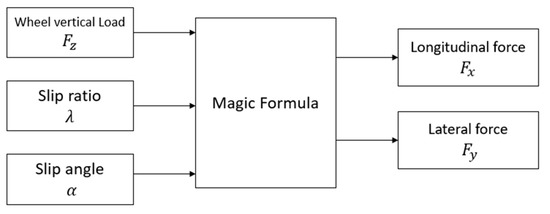
Figure 1.
Magic Formula inputs and outputs.
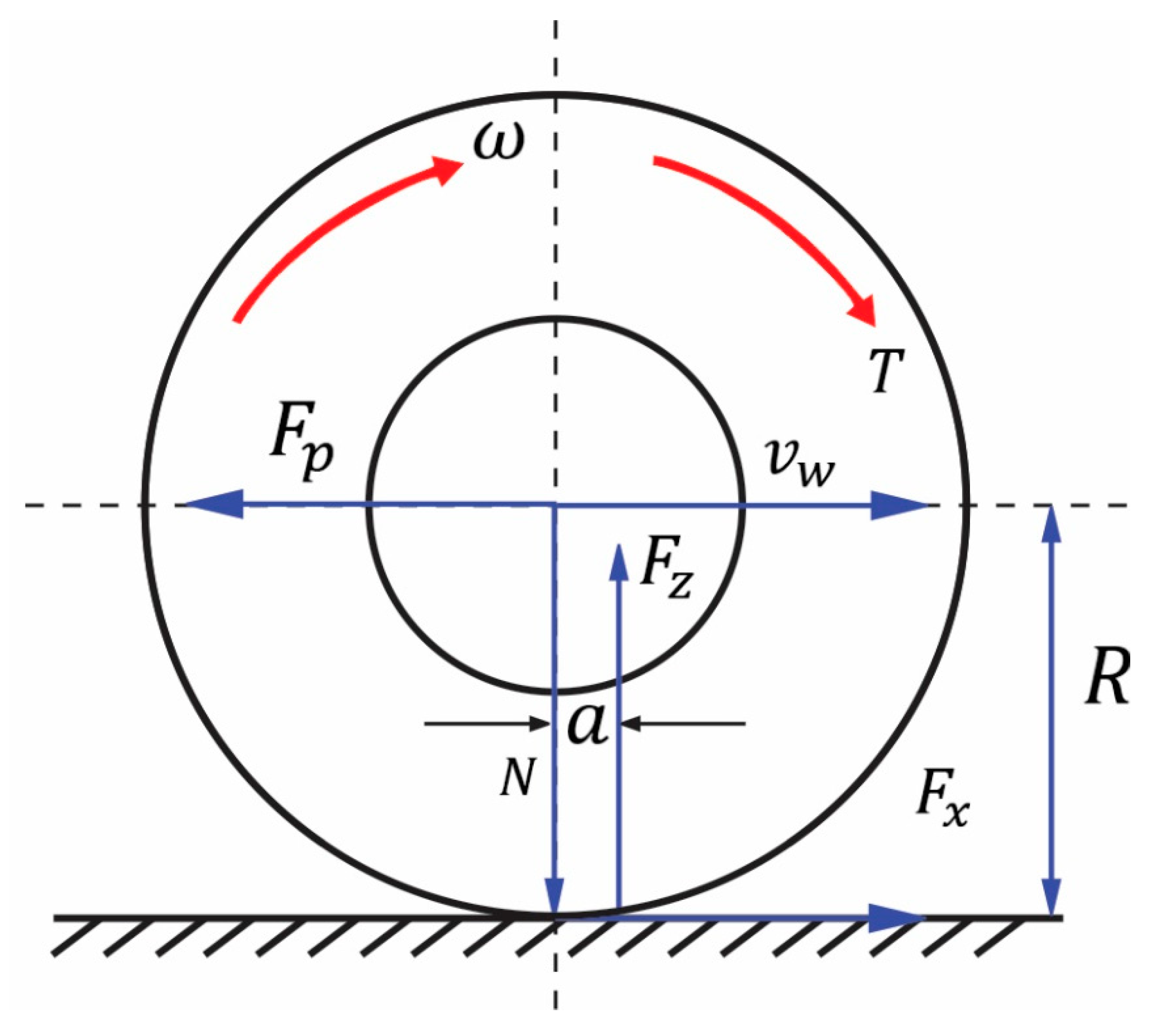
The wheel equation of motion Equation (5) is applied to calculate the wheel slip ratio, one of the inputs of the Magic Formula, and it is also used to find the wheel angular velocity. Equation (5) is applied based on the force wheel system shown in Figure 2. It can be found as:
where is the mass moment of inertia of the wheel, and denotes the angular velocity of the wheel, is the motor torque, is the longitudinal tire force and is the normal tire force, is the radius of the tire is the center wheel velocity, N is the wheel normal load, and is the pneumatic trail of the tire.

Figure 2.
Wheel force system schematic [22].
3. Proposed Controllers
In this section, three independent DYC algorithms are designed to control the yaw rate, the sideslip angle, and the vehicle’s longitudinal velocity, simultaneously. Each control method has three controllers to minimize the error between the desired yaw rate, sideslip angle and actual values in order to enhance vehicle handling and stability. The general block diagram for the closed loop control system is shown in Figure 3.
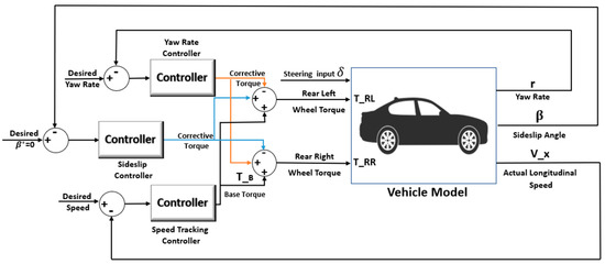
Figure 3.
The Closed Loop DYC Control System.
3.1. Desired Values Generation
The desired yaw rate is generated from the 2-DOF linear bicycle model based on the longitudinal vehicle velocity, input steering angle, and the distance between the front and rear axles as follows [26]:
where is the wheelbase, is the estimated longitudinal velocity, is the steering angle computed by the steering wheel angle sensor [27].
The desired vehicle speed is selected by the driver. The sideslip angle needs to be minimized because when the sideslip increases to large values, the cornering stiffness of the tires decreases [22]. No sideslip in the vehicle dynamics is considered therefore the desired sideslip angle is zero.
3.2. Proposed Control Methods
The first proposed control method consists of three optimized PID controllers for the three parameters: yaw rate, sideslip angle, and longitudinal speed. This method is achieved by using three PID controllers in the block diagram shown in Figure 4. As illustrated in the diagram, the input of each controller is the desired value. The output of the speed-tracking PID controller is the base torque of the driving wheels. The yaw rate PID controller’s output is a corrective torque added to the right driving wheel and subtracted from the left driving wheel. The corrective output torque from the sideslip angle PID controller is added to the left rear wheel and subtracted from the right rear wheel, Equations (7) and (8).
where and are the left rear and the right rear wheels’ torques, respectively. is the base torque the output of the speed-tracking controller, is the corrective torque from the sideslip angle controller and is the corrective torque from the yaw rate controller. The parameters of all optimized PID gains used in this work are shown in Table 1.
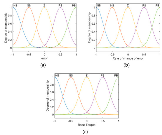
Figure 4.
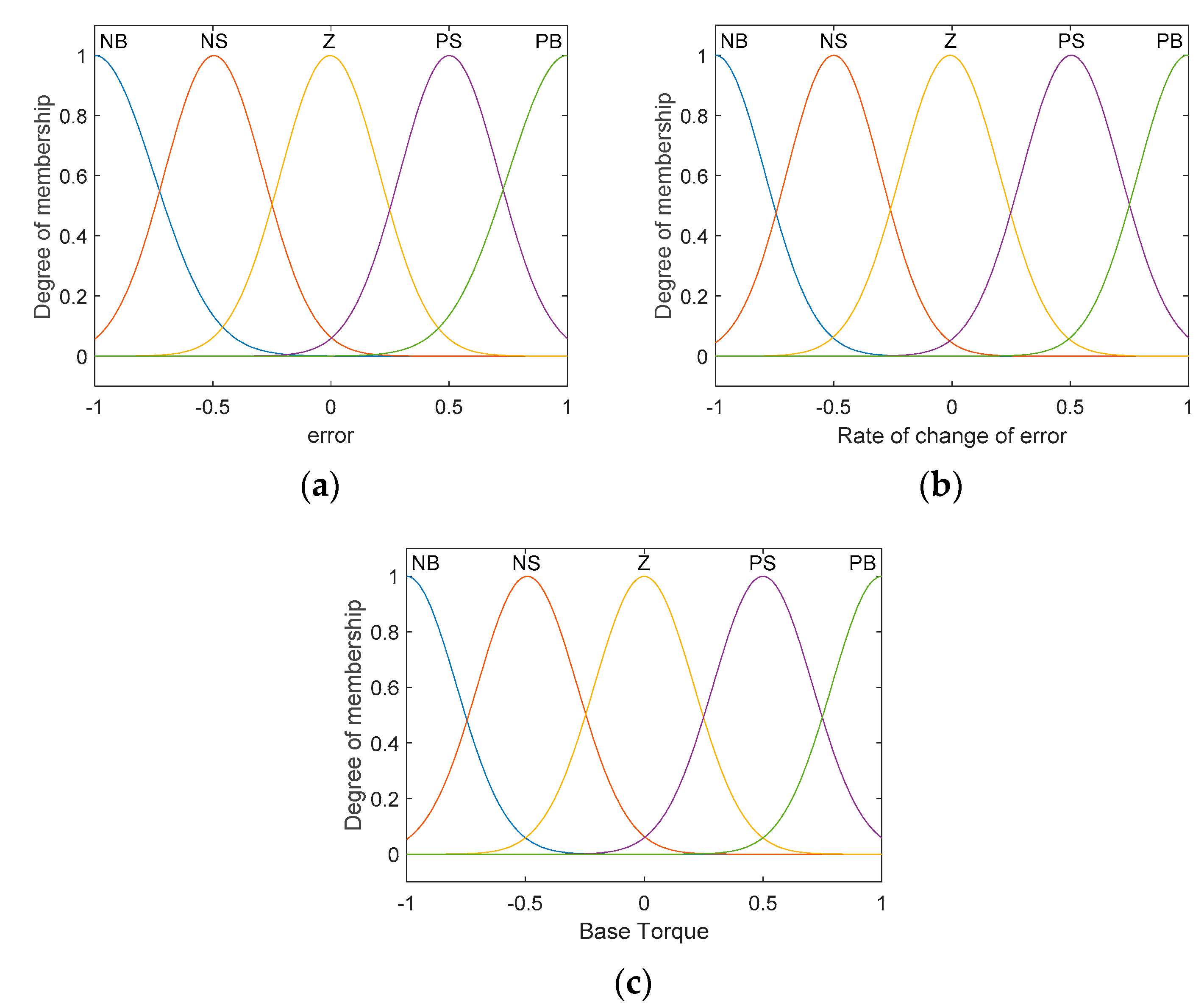
The membership functions of (a) the error, (b) rate change of the error, and (c) base toque.

Table 1.
Gains of Optimized PID controllers.
The second designed controller is based on fuzzy logic. In this method, each controller in Figure 4 is replaced by a fuzzy controller. The fuzzy controller is chosen to handle the high nonlinearity of the vehicle dynamics due to its robustness and ease to implement [28]. Each fuzzy controller is used to track the desired value explained in the previous section. The controller’s inputs are the error between the desired and the actual values and the rate of change of the error. The output of the speed-tracking fuzzy controller is the driver wheels’ base torque. The outputs of the yaw rate and sideslip angle fuzzy controllers are the corrective torques to improve vehicle stability performance while turning.
The type of fuzzy used in this paper is of Mamdani type. All of the inputs and outputs of the three fuzzy controllers have five membership functions (MFs), namely, Negative Large (NL), Negative Small (NS), Zero (Z), Positive Small (PS), and Positive Large (PL). The type of used MFs is Gaussian because it is smooth, precise, and accurate [29]. All MFs have a normalized range from −1 to 1. The membership functions for these variables are shown in Figure 4. The three fuzzy controllers have the same fuzzy rules as those presented in Table 2.
Table 2.
Fuzzy rules.
The last control method combines PID with the fuzzy controllers. In this approach, the yaw rate and the sideslip variables are controlled by using fuzzy controllers designed in the previous method. At the same time, the longitudinal speed is controlled by using the optimized speed-tracking PID that is designed in the three-PID-controllers method. It was not clear why much research in the literature used PID for controlling speed as presented in [30,31,32].
4. Simulation Results
The complete vehicle model used in this article was built and verified using Simulink. The vehicle parameters used in the simulation study were taken from an actual electric racing vehicle built at Royal Melbourne Institute of Technology University (RMIT); for more details the readers are encouraged to check [22]. This car has two independent rear-wheel driving motors.
The optimization of the PID and the fuzzy controllers’ inputs and output gains were achieved through the “Response Optimization” tool in Matlab using “Optimization Toolbox” and “Global Optimization Toolbox.
The proposed control methods were compared with three other controllers: The first one is the equal torque controller, which provides the same torque signal for each driving wheel. It consists of the longitudinal-speed-tracking PID controller designed in [22] The second controller is a fuzzy yaw-rate-based DYC, which tracks only the desired yaw rate using the yaw rate fuzzy controller explained earlier. The third control method is the fuzzy sideslip-based DYC, which individually controls the sideslip angle value to keep it close to the zero desired value.
Circular-Path Driving Test
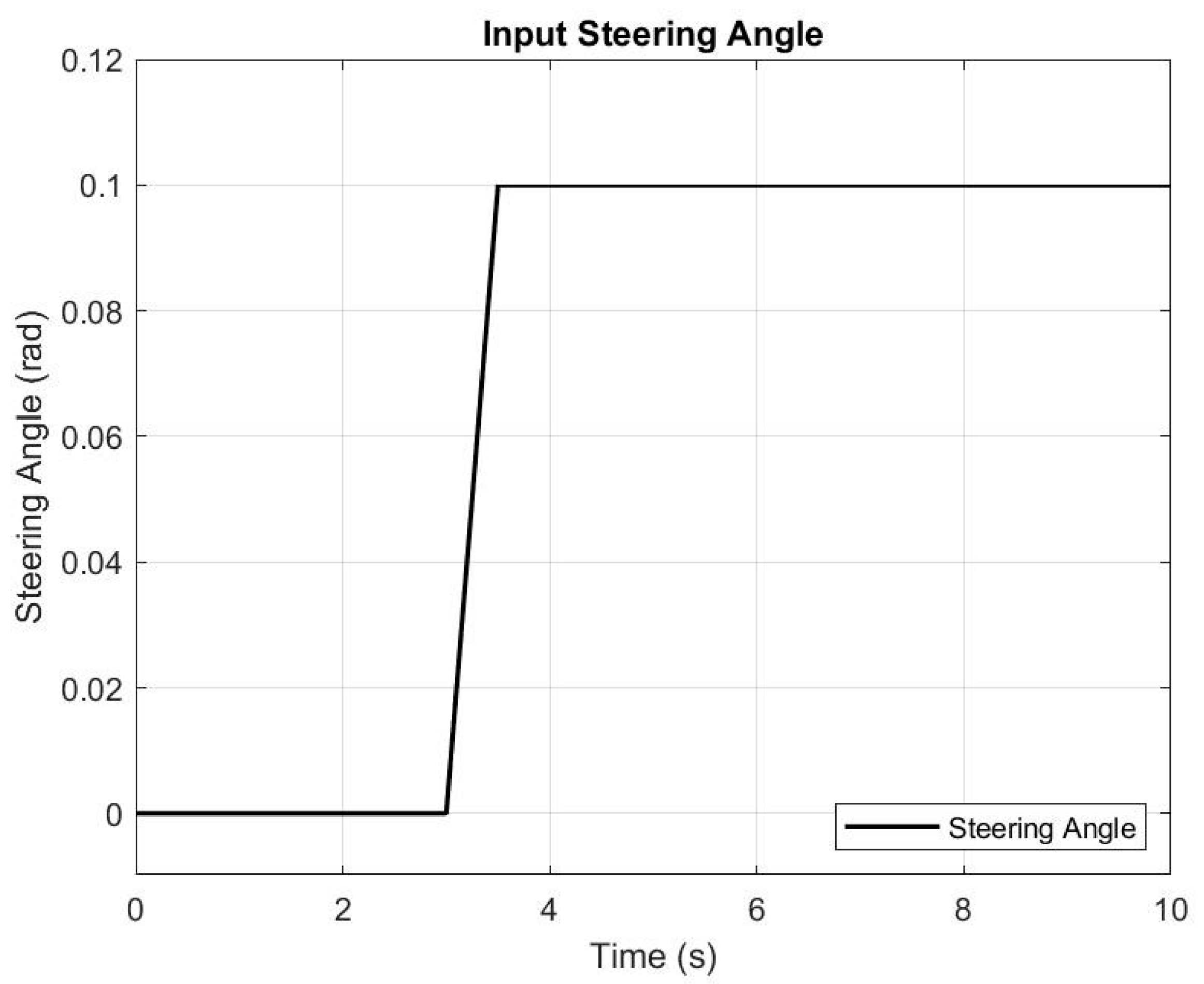
The rear-wheel-drive electric racing car model in this paper is tested under a circular-path maneuver. The circular path is achieved through a step input steering angle or ramp input with a short increasing time. Ramp input has a “softer” response than step input [33]. After trying both, the simulations showed that step input cause very high errors at the step instant, which provides a tremendous amount of torque at that moment; however, ramp input showed more stable and realistic behavior. The selected ramp steering input is shown in Figure 5. This signal is applied to the racing vehicle under the six control methods to find the best performance and stability. The longitude desired speed remains constant during the simulation at 20 m/s (72 km/h). Simulation time is selected to be ten seconds.
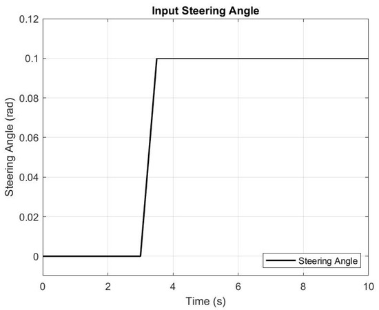
Figure 5.
Ramp steering angle input for circular-path maneuver.
The sideslip response in Figure 6 shows that the equal torque, yaw rate fuzzy, and the three PID controllers cannot handle the vehicle to keep stable while turning in a circular path at the desired speed. The sideslip fuzzy controller achieves the minimum sideslip root mean square error (RMS) error with a value of 0.0053. The three-fuzzy-controllers method has an RMS error of about 0.0095, and the fuzzy with the PID control method has a relative RMS error value of 0.0105. These three control methods can keep the vehicle stable while turning.
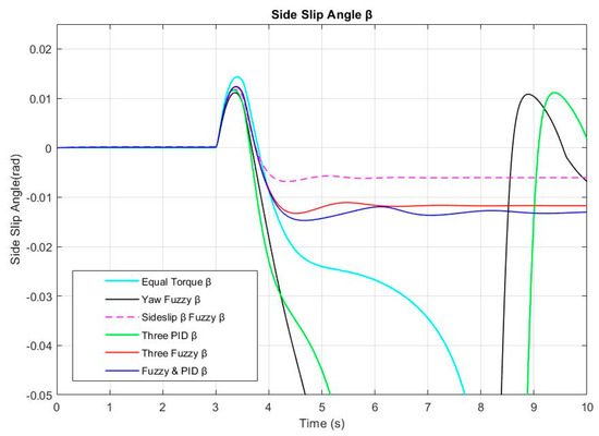
Figure 6.
Sideslip angle response for the six control methods.
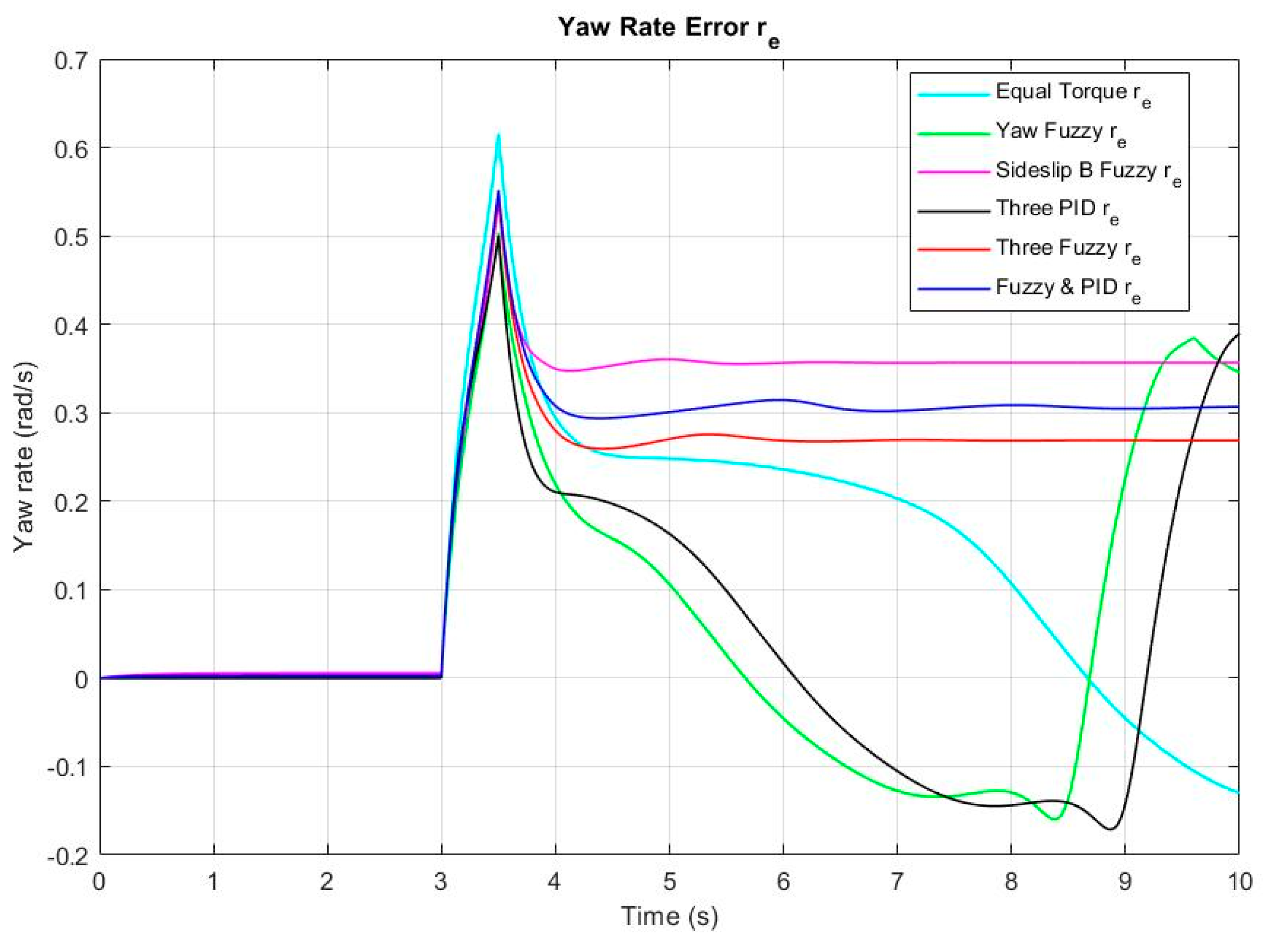
Yaw rate error responses are represented in Figure 7. Yaw rate error response for the six control methods. The more stable responses are produced by sideslip fuzzy, three fuzzies, and fuzzy with PID, which have RMS yaw rate error values of 0.299, 0.237, and 0.2634, respectively.
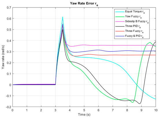
Figure 7.
Yaw rate error response for the six control methods.
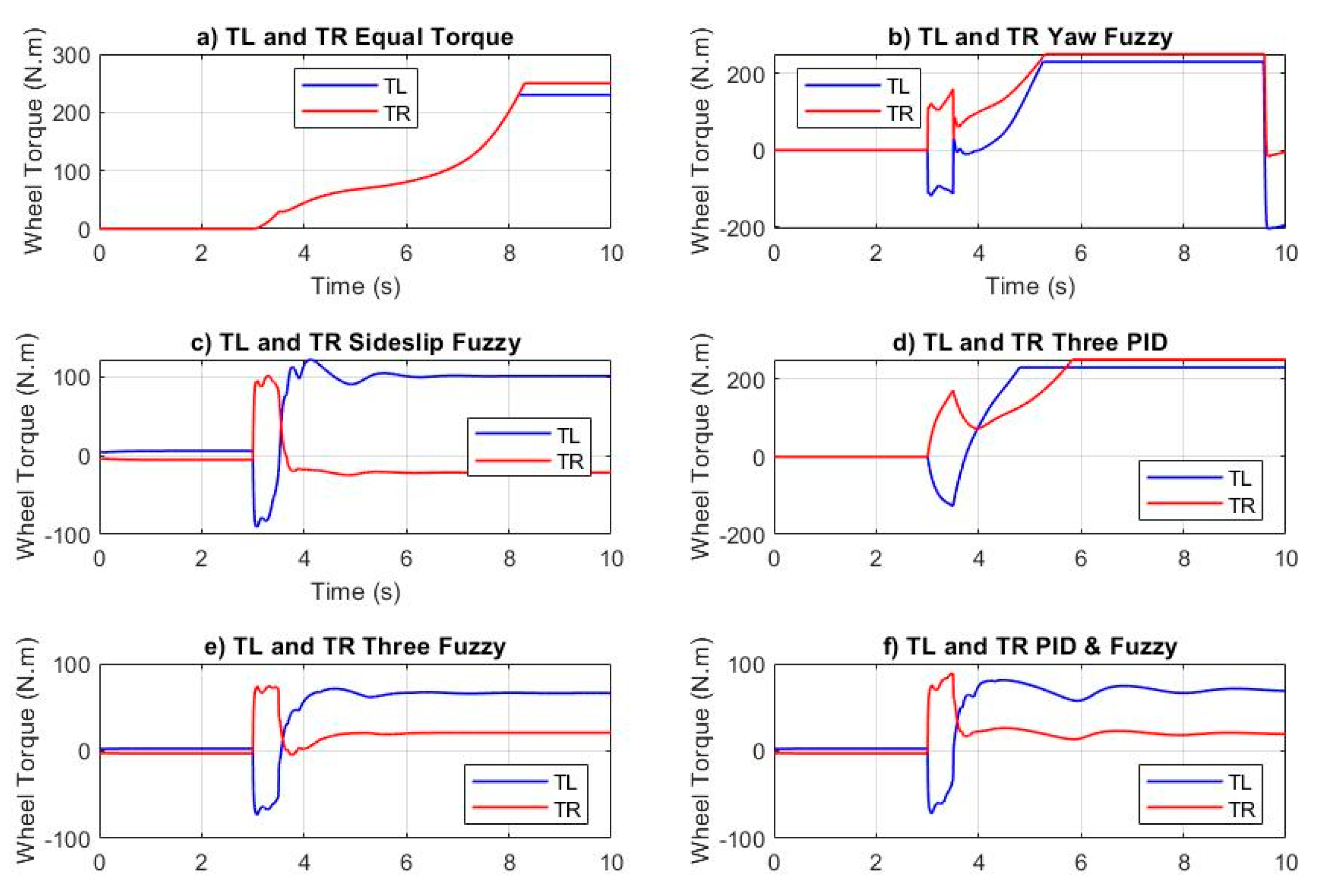
The torque input signals of the driving rear wheels of the six control methods are shown in Figure 8. As the figure illustrates, the plots of three controllers reached saturation. These controllers are equal torque, yaw rate fuzzy, and three PIDs. These three controllers also showed large sideslip-angle error and yaw-rate error as in Figure 6 and Figure 7. The sideslip fuzzy has a maximum torque of about 122 N·m and minimum torque of almost −86 N·m. The steady-state torque values of the left and right wheels (TL and TR) are about 101 and −22 N·m, respectively. The three fuzzy control method’s extreme values are around 71 N·m and −67 N·m, and steady-state torque values are 21 N·m and 66 N·m for the right and left wheels, respectively. The fuzzy with the PID control method has a maximum torque of about 89 N·m and a minimum of almost −71 N·m; the left wheel’s steady-state torque is around 69 N·m and of the right about 21 N·m. The three fuzzy control method has the minimum input torque.
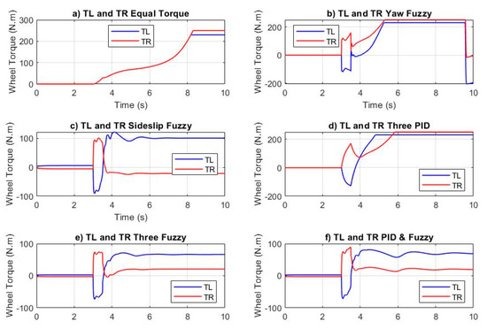
Figure 8.
Torque input of the driving right and left rear wheels: (a): Equal torque controller, (b): Yaw rate fuzzy controller, (c): Sideslip angle fuzzy controller, (d): Three PID controllers, (e): Three fuzzy controllers, (f): Fuzzy and PID controllers.
The power of both wheels in each case is calculated by multiplying torque and angular velocity curves. The energy is calculated as the area under the power curve [34,35]. Based on the angular velocity and the driving wheels’ torque, the required energy is calculated for the three stable control methods. The sideslip fuzzy control method has the maximum required energy of approximately 67.84 kJ and 18.87 kJ for the left and right rear wheels. The fuzzy with PID method has about 46.25 kJ and 17.10 kJ, and the three fuzzy control method has 41.97 kJ and 15.27 kJ for the left and right driving wheels, respectively, which is the minimum energy consumed among all control methods.
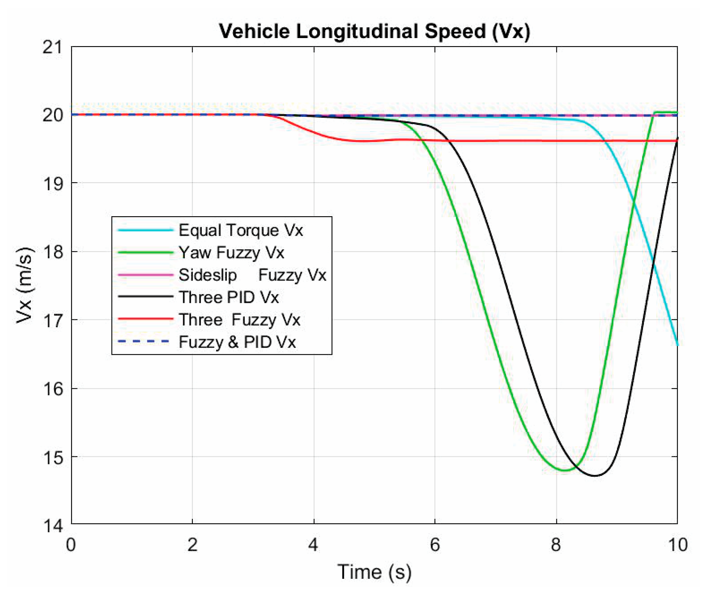
The longitudinal speed response of all controllers is shown in Figure 9. The sideslip angle fuzzy and fuzzy with PID control methods have the closest value to the desired value of 20 m/s. The three fuzzy control method has a final desired velocity of 19.62 m/s with a steady-state error of 1.9%. In contrast, the other three methods, namely, equal torque, yaw rate fuzzy, and three PID, have faraway values that decrease to less than 15 m/s.
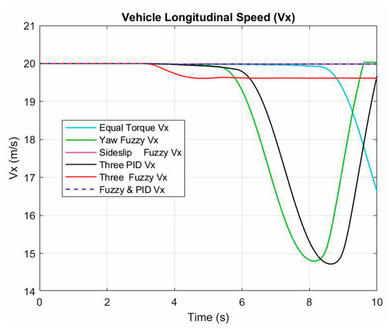
Figure 9.
Longitudinal speed response of the six control methods.
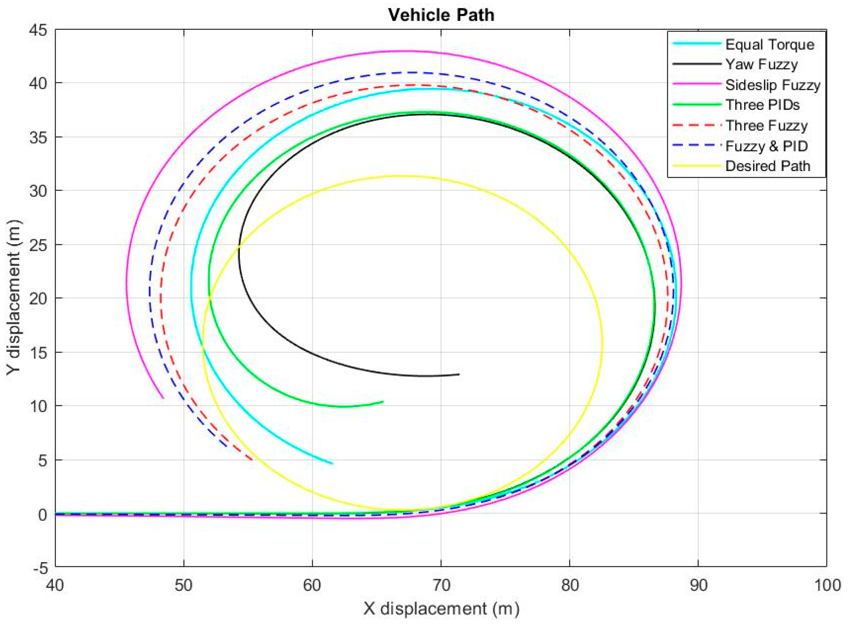
The simulation is run for 9 s to be able to find the fastest control method, and the result as shown in Figure 10. Among the six methods, the sideslip fuzzy method is the slowest one and has the farthest path from the desired path. In comparison, the three-fuzzy-controllers method is slightly faster than the fuzzy with the PID control method, which means the vehicle will complete the circular path first. The yaw rate fuzzy controller and the three-fuzzy-controller methods’ paths are almost identical, which are the closest complete paths to the desired one.
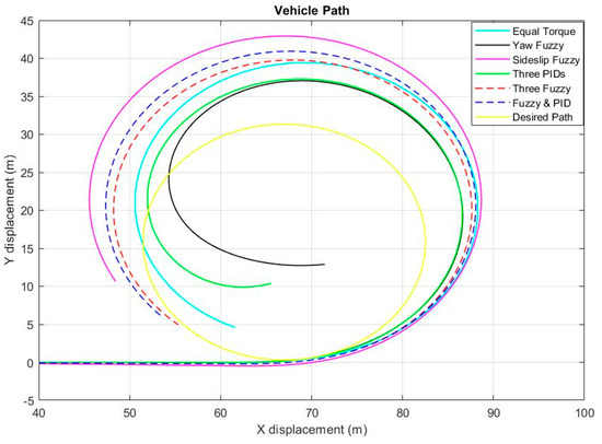
Figure 10.
Vehicle path during 9 s simulation time.
The results under the circular-path test of the six different DYC-based control methods show that in three controller methods, namely, equal torque, fuzzy yaw-rate-based DYC, and three optimized PIDs, the vehicle loses stability while cornering under the speed of 20 m/s (72 km/h). The comparison between the other three controllers’ performance shows that the three-fuzzy-controllers method has the minimum yaw rate and sideslip angle RMS errors, and it completed the circular path faster than the other method. It has less required input torque and consumed energy. It can be concluded that the three fuzzy controllers for yaw rate, sideslip angle, and speed-tracking approach are the most appropriate methods to control a rear-wheel-drive electric racing car with two independent motors under the circular-path driving scenario.
5. Conclusions
In this paper, three combinations of fuzzy and PID DYC schemes are proposed to control the vehicle’s yaw rate, sideslip angle, and longitudinal velocity for a rear-wheel drive student racing EV with an independent motor per driving wheel. These controllers are designed to improve vehicle-cornering performance and stability by controlling the amount of torque for each driving wheel. The designed controllers are tested using SIMULINK by following a circular-path maneuver and longitudinal speed of 20 m/s (72 km/h). The three-fuzzy-controllers DYC method outperformed the other tested controllers, namely, three optimized PID controllers and fuzzy with PID method. The aforementioned method minimized both yaw rate and sideslip angle RMS errors and the power consumption. In addition, it enhanced vehicle-cornering performance under higher longitudinal speed without compromising the EV stability.
Author Contributions
Conceptualization, L.S.S. and I.H.R.; methodology, I.H.R.; software, I.H.R.; validation, I.H.R.; formal analysis I.H.R.; investigation, I.H.R.; resources, I.H.R.; writing—original draft preparation I.H.R.; writing—review and editing, L.S.S.; visualization, I.H.R.; supervision, L.S.S.; project administration, L.S.S. All authors have read and agreed to the published version of the manuscript.
Funding
This research received no external funding.
Data Availability Statement
Not applicable.
Conflicts of Interest
The authors declare no conflict of interest.
References
- Un-noor, F.; Padmanaban, S.; Mihet-popa, L. A Comprehensive Study of Key Electric Vehicle (EV) Components, Technologies, Challenges, Impacts, and Future Direction of Development. Energies 2017, 10, 1217. [Google Scholar] [CrossRef] [Green Version]
- Ying, J.; Ramachandaramurthy, V.K.; Miao, K.; Mithulananthan, N. A review on the state-of-the-art technologies of electric vehicle, its impacts and prospects. Renew. Sustain. Energy Rev. 2015, 49, 365–385. [Google Scholar] [CrossRef]
- Tie, S.F.; Wei, C. A review of energy sources and energy management system in electric vehicles. Renew. Sustain. Energy Rev. 2013, 20, 82–102. [Google Scholar] [CrossRef]
- Ivanov, V.; Savitski, D.; Member, S.; Lock, N.T.I. A Survey of Traction Control and Anti-lock Braking Systems of Full Electric Vehicles with Individually-Controlled Electric Motors. IEEE Trans. Veh. Technol. 2014, 64, 3878–3896. [Google Scholar] [CrossRef]
- Novellis LDe Sorniotti, A.; Gruber, P.; Pennycott, A. Comparison of Feedback Control Techniques for Torque—Vectoring Control of Fully Electric Vehicles. IEEE Trans. Veh. Technol. 2014, 63, 3612–3623. [Google Scholar] [CrossRef]
- Jing, H.; Jia, F.; Liu, Z. Multi-Objective Optimal Control Allocation for an Over-Actuated Electric Vehicle. IEEE Access 2018, 6, 4824–4833. [Google Scholar] [CrossRef]
- Jang, Y.; Lee, M.; Suh, I.-S.; Nam, K.H. Lateral Handling Improvement with Dynamic Curvature Control for an Independent Rear Wheel Drive EV. Intern. J. Auto. Technol. 2017, 18, 505–510. [Google Scholar]
- Jalali, K. Stability Control of Electric Vehicles with In-Wheel Motors. Ph.D. Thesis, University of Waterloo, Waterloo, ON, Canada, 2010; p. 256. [Google Scholar]
- Kelecy, P.M.; Lorenz, R.D. Control methodology for single inverter, parallel connected dual induction motor drives for electric vehicles. PESC Rec. IEEE Annu. Power Electron. Spec. Conf. 1994, 2, 987–991. [Google Scholar]
- Profumo, F.; Zhang, Z.; Tenconi, A. Axial flux machines drives: A new viable solution for electric cars. IEEE Trans. Ind. Electron. 1997, 44, 39–45. [Google Scholar] [CrossRef]
- Buckholtz, K.R. Use of Fuzzy Logic in Wheel Slip Assignment—Part I: Yaw Rate Control; SAE Technical Paper; SAE: Warrendale, PA, USA, 2002. [Google Scholar]
- Chen, Y.; Hedrick, J.K.; Guo, K. A novel direct yaw moment controller for in-wheel motor electric vehicles. Veh. Syst Dyn. 2013, 51, 925–942. [Google Scholar] [CrossRef]
- Fu, C.; Hoseinnezhad, R.; Jazar, R.; Bab-Hadiashar, A.; Watkins, S. Electronic differential design for vehicle side-slip control. In Proceedings of the 2012 International Conference on Control, Automation and Information Sciences (ICCAIS), Saigon, Vietnam, 26–29 November 2012; pp. 306–310. [Google Scholar]
- Abe, M. Vehicle dynamics and control for improving handling and active safety: From four-wheel steering to direct yaw moment control. Proc. Inst. Mech. Eng. Part K. J. Multi-Body Dyn. 1999, 213, 87–101. [Google Scholar] [CrossRef]
- Research on Vehicle Stability Based on DYC and AFS Integrated Controller. Available online: https://www.scientific.net/AMM.278-280.1510 (accessed on 7 May 2022).
- Tchamna, R.; Youn, I. Yaw Rate and Side-Slip Control Considering Vehicle Longitudinal Dynamics. Int. J. Automot. Technol. 2013, 14, 53–60. [Google Scholar] [CrossRef]
- Van Zanten, A.T.; Erhardt, R.; Pfaff, G. VDC, The Vehicle Dynamics Control System of Bosch; SAE Technical Paper; SAE: Warrendale, PA, USA, 1995. [Google Scholar]
- Parra, A.; Dendaluce, M.; Zubizarreta, A.; Pérez, J. Novel Fuzzy Torque Vectoring Controller for Electric Vehicles with Per-Wheel Motors. In Proceedings of the Actas las XXXVIII Jornadas Automática, Gijón, Spain, 6–8 September 2017. [Google Scholar]
- Design of Active Roll Control System and Integrated Chassis Control for Hybrid 4WD Vehicles. Available online: https://ieeexplore.ieee.org/abstract/document/6082889 (accessed on 7 May 2022).
- Street, F. Integrated AFS/DYC sliding mode controller for a hybrid electric vehicle. Int. J. Veh. Des. 2011, 56, 246–269. [Google Scholar]
- Kwak, B.; Park, Y. Robust Vehicle Stability Controller Based On Multiple Sliding Mode Control; SAE Technical Paper; SAE: Warrendale, PA, USA, 2001. [Google Scholar]
- Fu, C. Direct Yaw Moment Control for Electric Vehicles with Independent Motors by Declaration of Authorship. 2014. Available online: http://citeseerx.ist.psu.edu/viewdoc/download?doi=10.1.1.660.4495&rep=rep1&type=pdf (accessed on 7 May 2022).
- Rowley, C.W.; Williams, D.R. Dynamics and control of high-Reynolds-number flow over open cavities. Annu. Rev. Fluid Mech. 2006, 38, 251–276. [Google Scholar] [CrossRef]
- Ren, H.; Shim, T.; Ryu, J.; Chen, S. Development of Effective Bicycle Model for Wide Ranges of Vehicle Operations; SAE Technical Paper; SAE: Warrendale, PA, USA, 2014; p. 1. [Google Scholar]
- Ahmadi, J.; Sedigh, A.K.; Kabganian, M. Adaptive vehicle lateral-plane motion control using optimal tire friction forces with saturation limits consideration. IEEE Trans. Veh. Technol. 2009, 58, 4098–4107. [Google Scholar] [CrossRef]
- Abe, M. Vehicle Handling Dynamics: Theory and Application, 2nd ed.; Elsevier: Amsterdam, The Netherlands, 2015; pp. 1–306. [Google Scholar]
- Jazar, R.N. Direct yaw moment control for electric and hybrid vehicles with independent motors. Int. J. Veh. Des. 2015, 69, 1–24. [Google Scholar]
- Taylor, P.; Tahami, F.; Farhangi, S.; Kazemi, R. A Fuzzy Logic Direct Yaw-Moment Control System for All-Wheel-Drive Electric Vehicles. Veh. Syst. Dyn. 2010, 41, 37–41. [Google Scholar]
- Viattchenin, D.A.; Tati, R.; Damaratski, A. Designing Gaussian membership functions for fuzzy classifier generated by heuristic possibilistic clustering. J. Inf. Organ. Sci. 2013, 37, 127–139. [Google Scholar]
- Zhai, L.; Hou, R.; Sun, T.; Kavuma, S. Continuous steering stability control based on an energy-saving torque distribution algorithm for a four in-wheel-motor independent-drive electric vehicle. Energies 2018, 11, 350. [Google Scholar] [CrossRef] [Green Version]
- Haiying, M.; Chaopeng, L.; Fu, W.Z. Direct Yaw-Moment Control Based on Fuzzy Logic of Four Wheel Drive Vehicle under the Cross Wind. Energy Procedia 2017, 105, 2310–2316. [Google Scholar] [CrossRef]
- Zhai, L.; Sun, T.; Wang, J. Electronic Stability Control Based on Motor Driving and Braking Torque Distribution for a Four In-Wheel Motor Drive Electric Vehicle. IEEE Trans. Veh. Technol. 2016, 65, 4726–4739. [Google Scholar] [CrossRef]
- Thesis, F.M. Control of a Four In-Wheel Motor Drive Electric Vehicle. Master’s Thesis, Universidad Politécnica de Cataluña, Bacelona, Spain, 2017. [Google Scholar]
- Zhao, B.; Xu, N.; Chen, H.; Guo, K.; Huang, Y. Stability control of electric vehicles with in-wheel motors by considering tire slip energy. Mech. Syst. Signal Process. 2018, 118, 340–359. [Google Scholar] [CrossRef]
- Cormie, P.; Mcbride, J.M.; Mccaulley, G.O. Squat: Impact of Load Power-Time, Force-Time, and Velocity-Time Curve Analysis During the Jump Squat: Impact of Load. J. Appl. Biomech. 2018, 24, 112–120. [Google Scholar] [CrossRef] [Green Version]


Publisher’s Note: MDPI stays neutral with regard to jurisdictional claims in published maps and institutional affiliations. |
© 2022 by the authors. Licensee MDPI, Basel, Switzerland. This article is an open access article distributed under the terms and conditions of the Creative Commons Attribution (CC BY) license (https://creativecommons.org/licenses/by/4.0/).