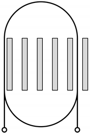
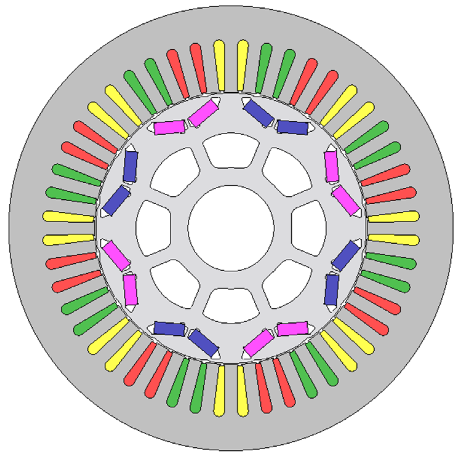
Figure 1.
Cross-section of the Toyota Prius 2010 machine.
Figure 1.
Cross-section of the Toyota Prius 2010 machine.
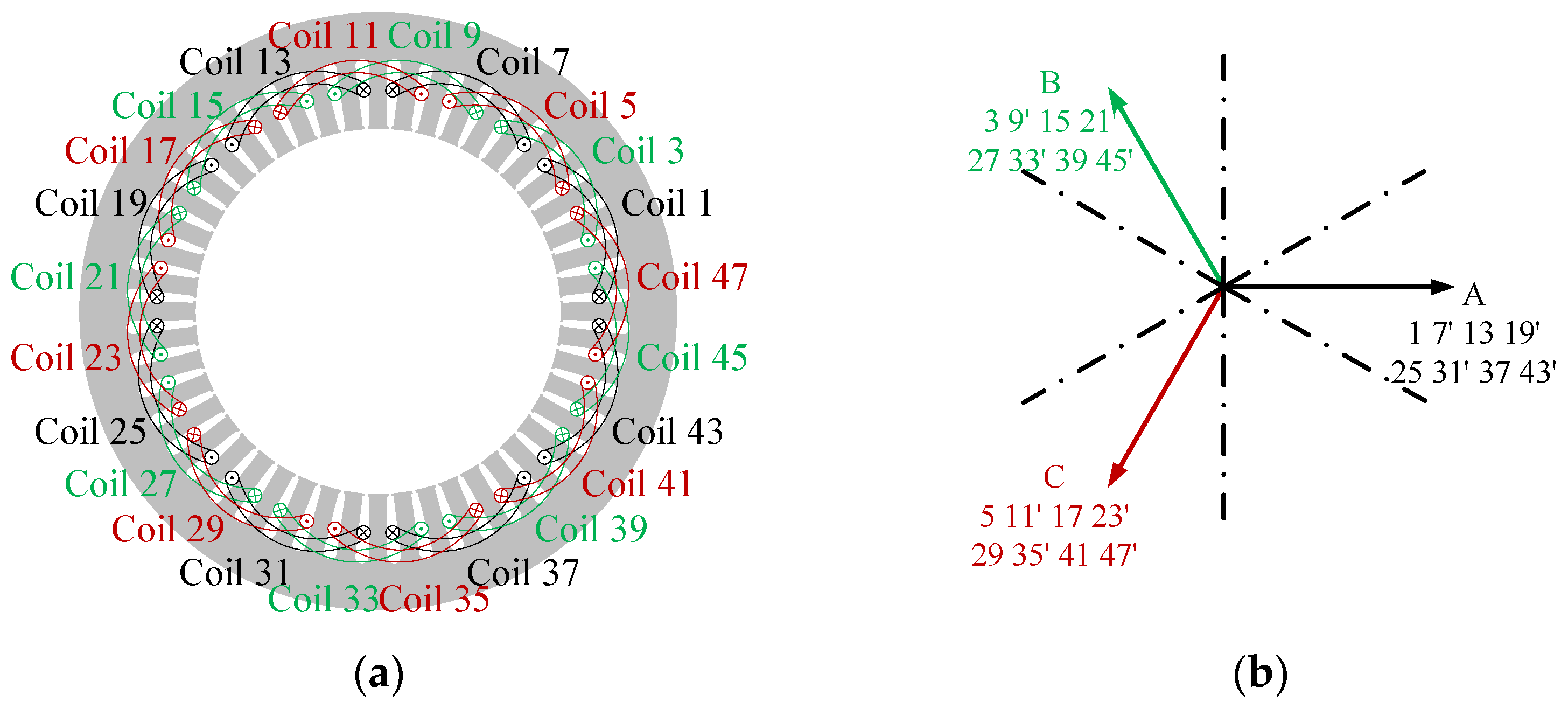
Figure 2.
Winding arrangements of Toyota Prius 2010 IPM machine: (a) winding layouts; (b) coil EMF phasor diagram.
Figure 2.
Winding arrangements of Toyota Prius 2010 IPM machine: (a) winding layouts; (b) coil EMF phasor diagram.
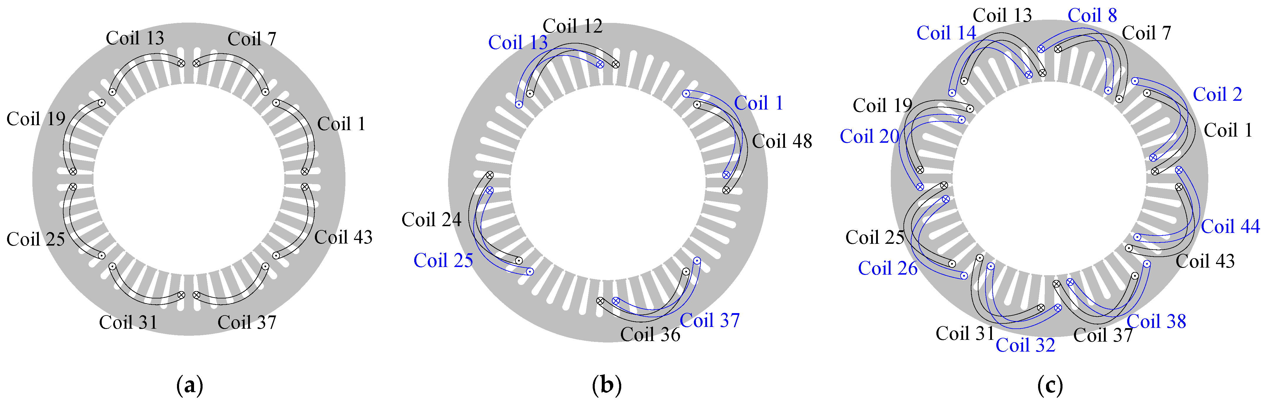
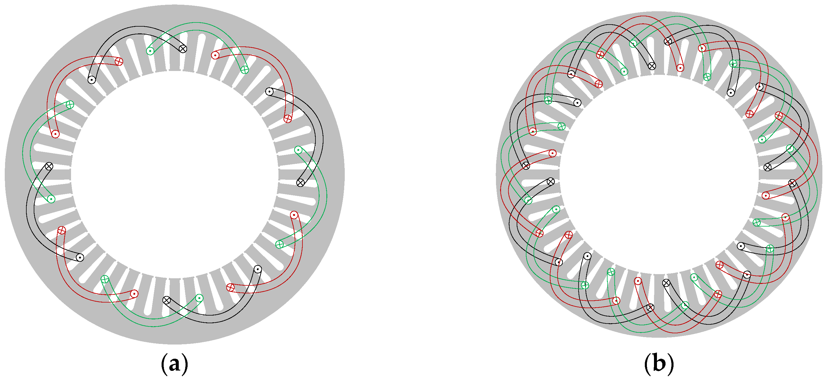
Figure 3.
Winding layouts of Phase A in ORG machine and Phases A1 and A2 in DTP machines: (a) ORG; (b) DTP-SF; (c) DTP-DS.
Figure 3.
Winding layouts of Phase A in ORG machine and Phases A1 and A2 in DTP machines: (a) ORG; (b) DTP-SF; (c) DTP-DS.
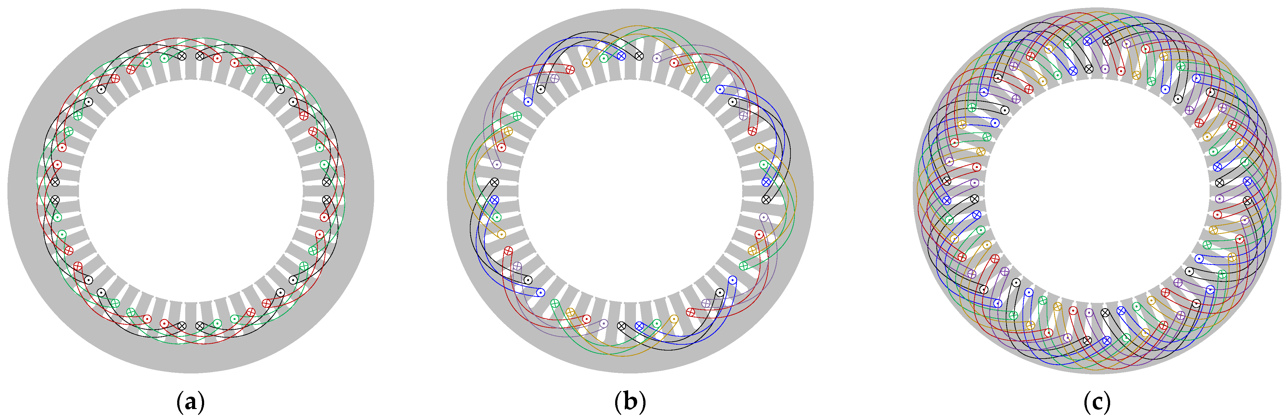
Figure 4.
Winding arrangements of different winding configurations: (a) ORG; (b) DTP-SF; (c) DTP-DS.
Figure 4.
Winding arrangements of different winding configurations: (a) ORG; (b) DTP-SF; (c) DTP-DS.
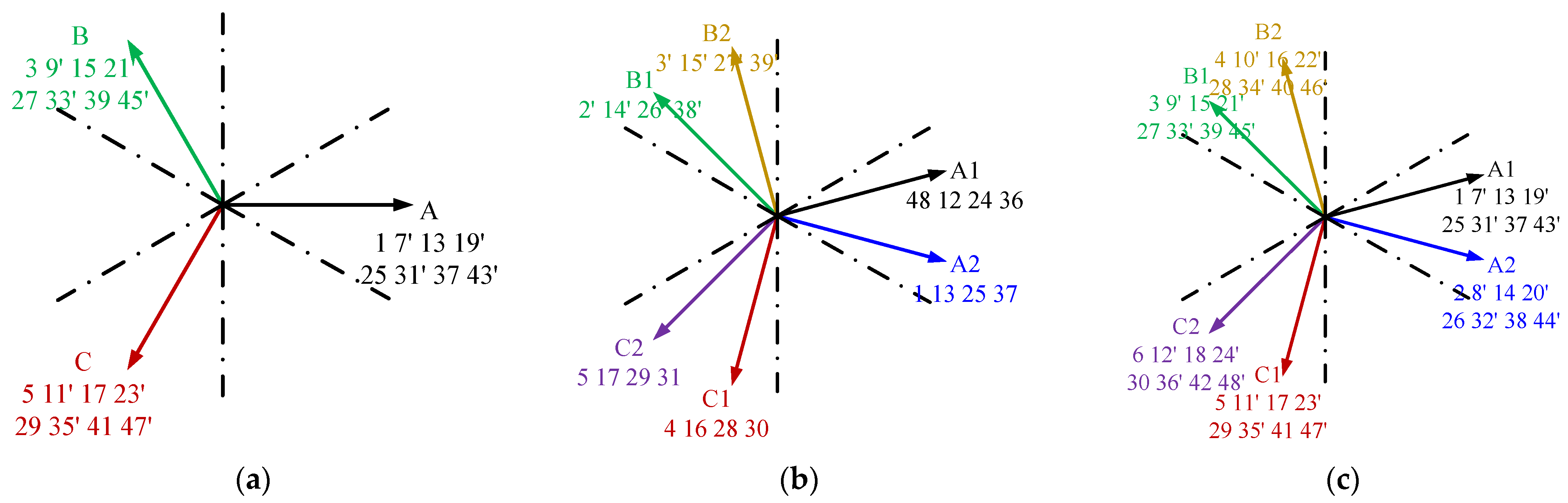
Figure 5.
Coil EMF phasor diagrams of different winding configurations: (a) ORG; (b) DTP-SF; (c) DTP-DS.
Figure 5.
Coil EMF phasor diagrams of different winding configurations: (a) ORG; (b) DTP-SF; (c) DTP-DS.
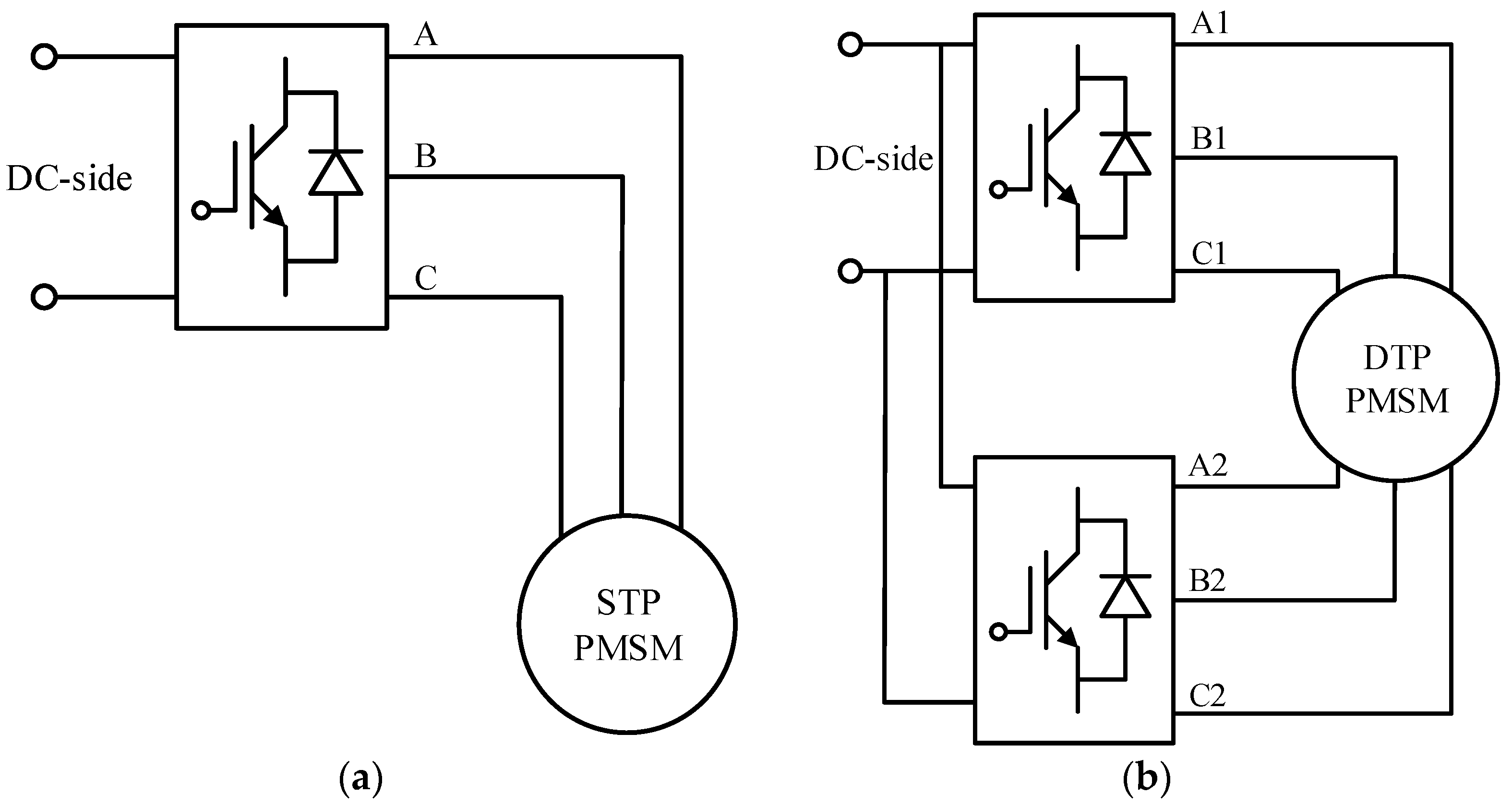
Figure 6.
Schematics of drive systems for different winding configurations: (a) ORG; (b) DTP-SF; DTP-DS.
Figure 6.
Schematics of drive systems for different winding configurations: (a) ORG; (b) DTP-SF; DTP-DS.
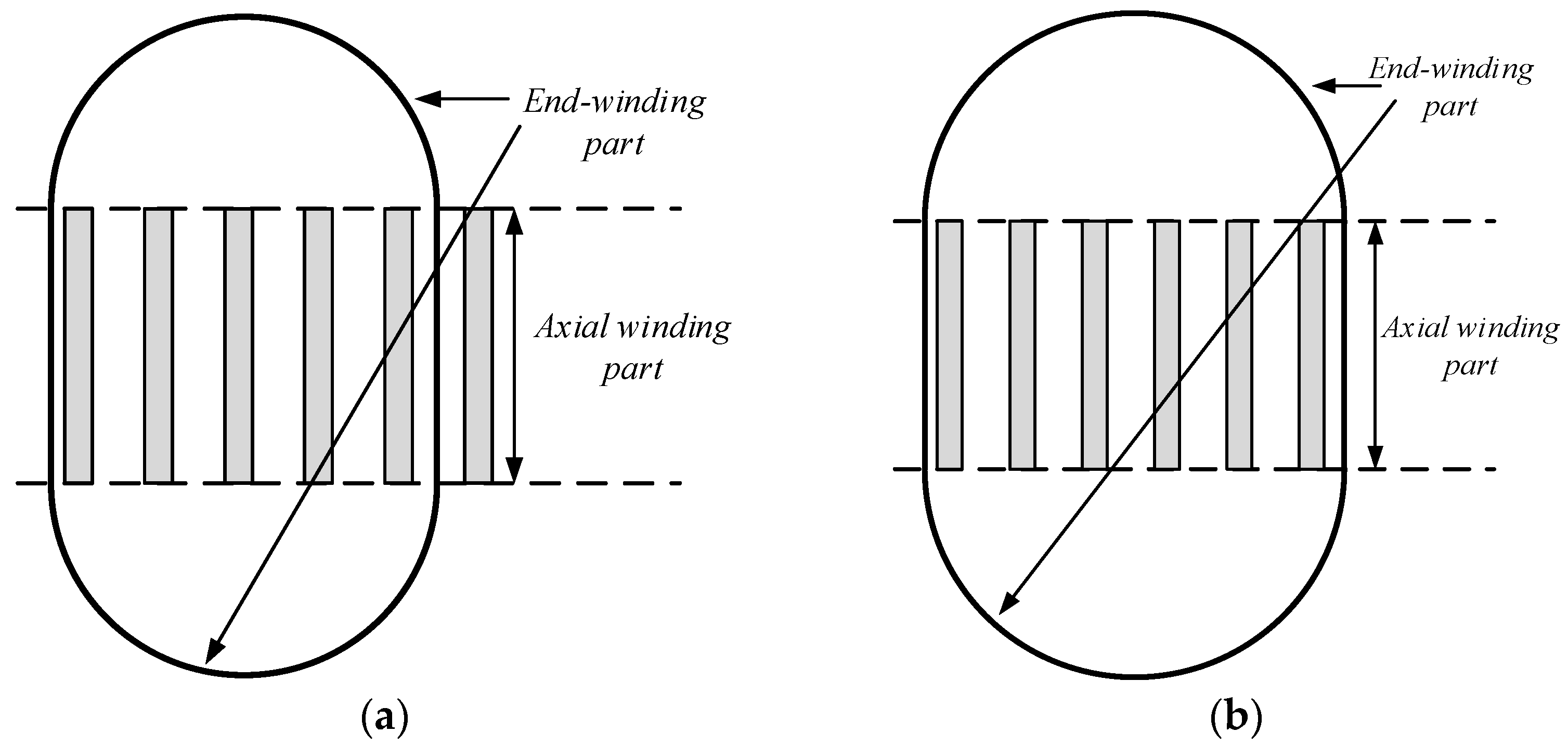
Figure 7.
Schemes of different coils: (a) short-pitched coil; (b) full-pitched coil.
Figure 7.
Schemes of different coils: (a) short-pitched coil; (b) full-pitched coil.
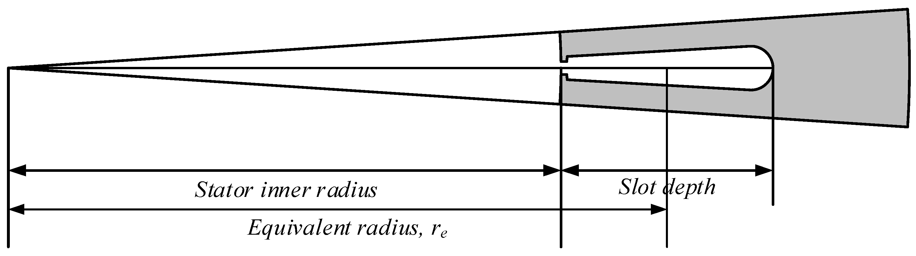
Figure 8.
Schematic of the equivalent radius of the coil side.
Figure 8.
Schematic of the equivalent radius of the coil side.
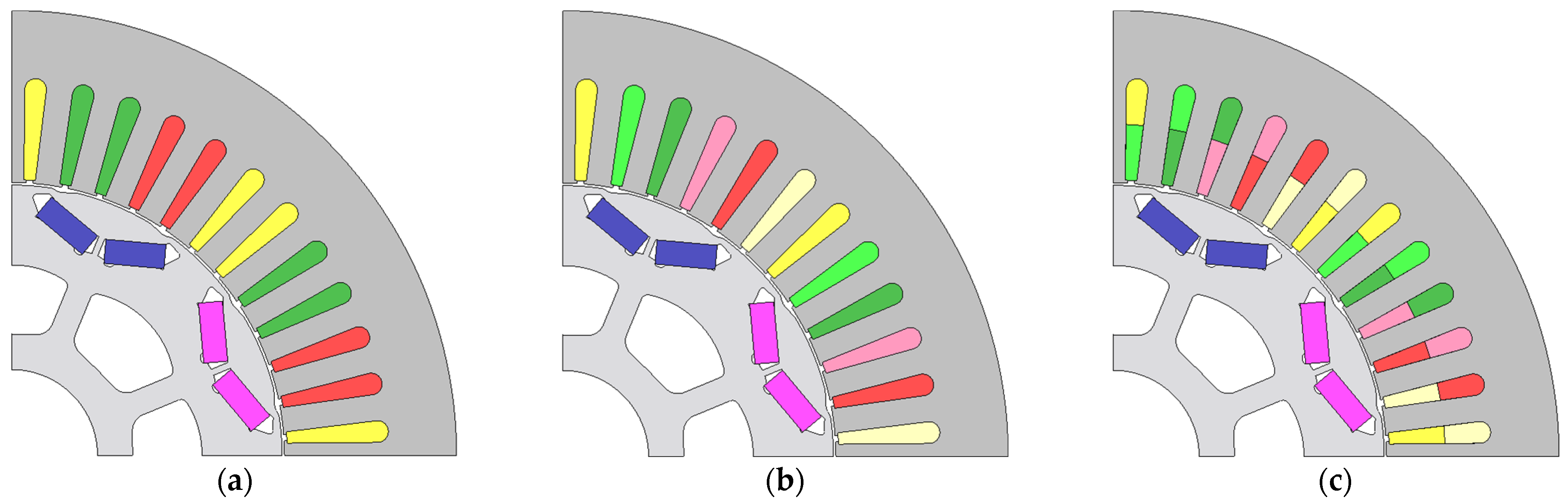
Figure 9.
One-fourth models of Prius 2010 machine with different winding configurations: (a) ORG; (b) DTP-SF; (c) DTP-DS.
Figure 9.
One-fourth models of Prius 2010 machine with different winding configurations: (a) ORG; (b) DTP-SF; (c) DTP-DS.
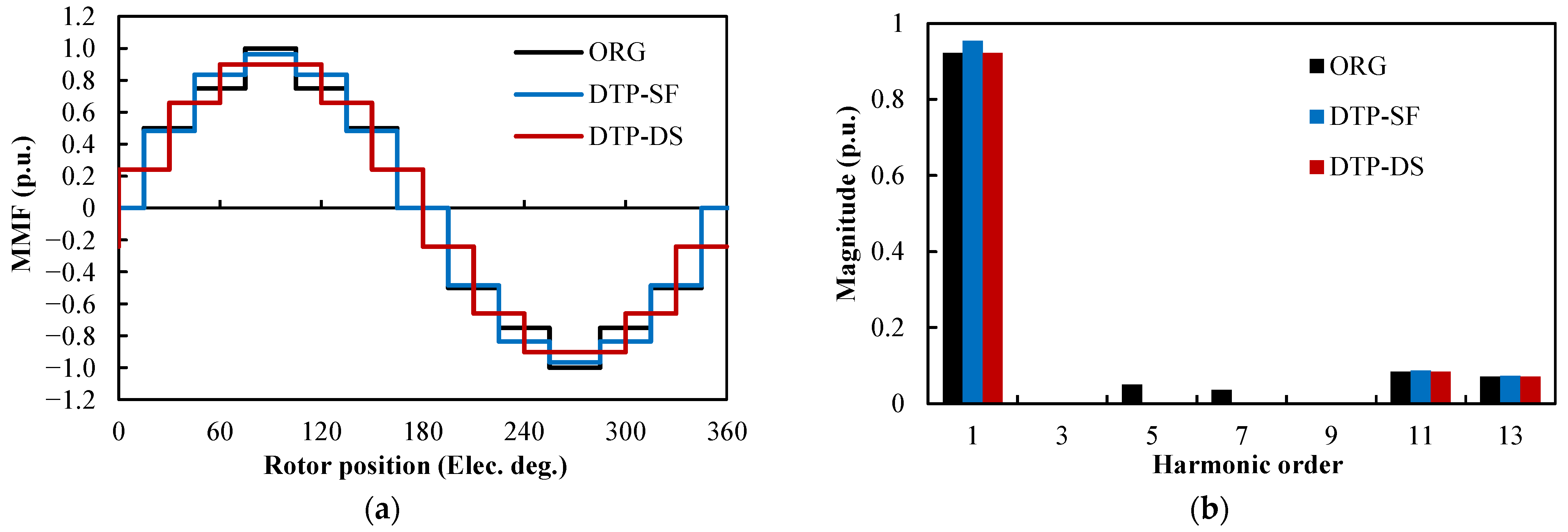
Figure 10.
Ideal stator MMF distributions for different winding configurations: (a) waveforms; (b) spectra.
Figure 10.
Ideal stator MMF distributions for different winding configurations: (a) waveforms; (b) spectra.
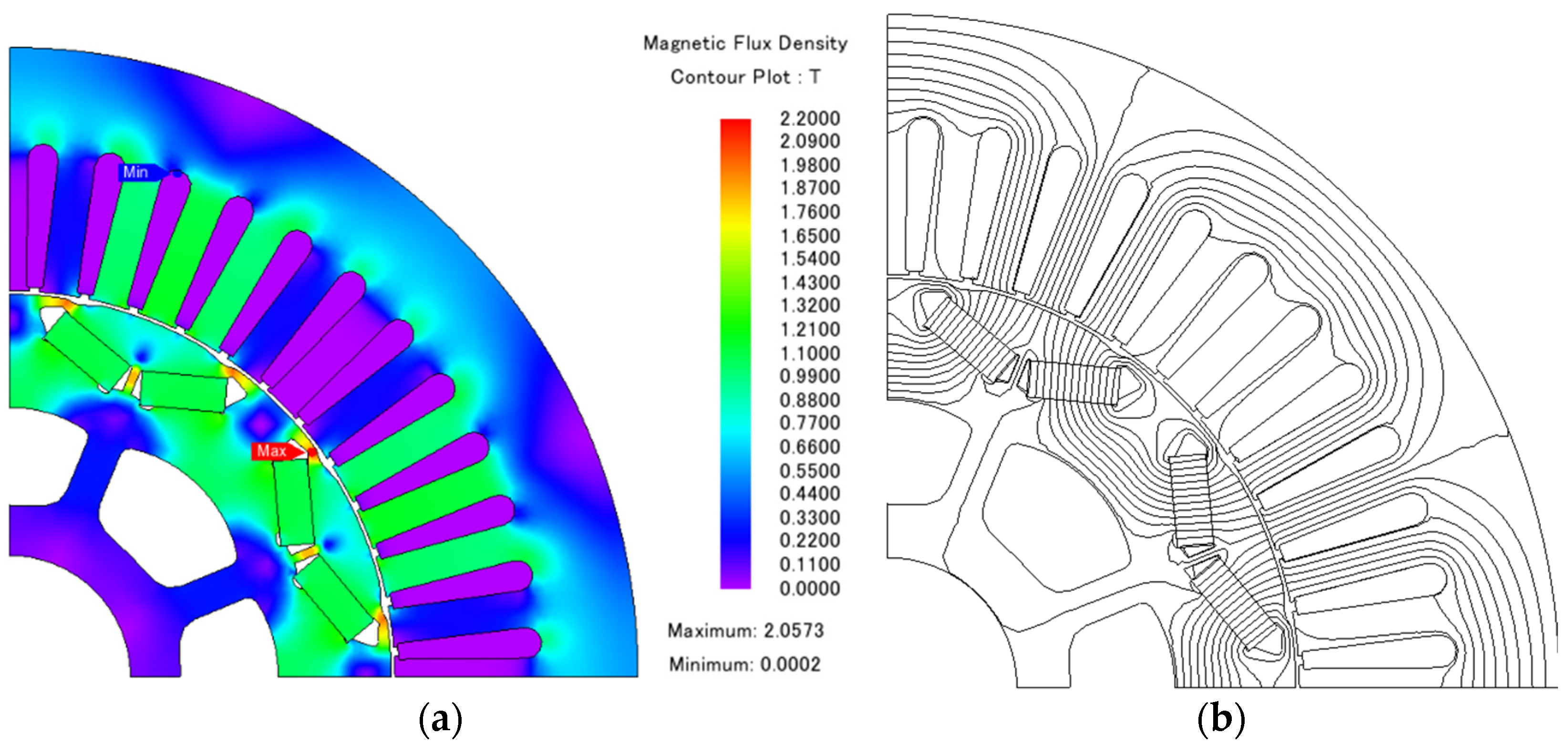
Figure 11.
Flux distribution of Prius 2010 machine under OC condition: (a) contour; (b) flux line distribution.
Figure 11.
Flux distribution of Prius 2010 machine under OC condition: (a) contour; (b) flux line distribution.
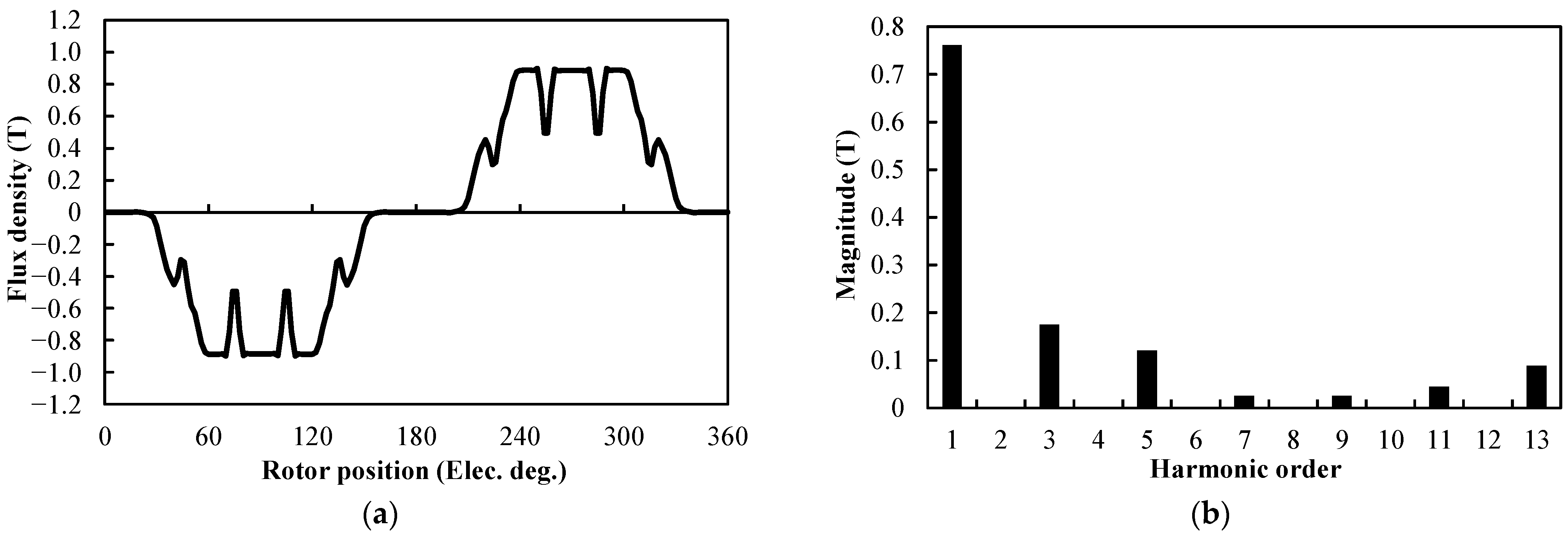
Figure 12.
Air-gap flux density distribution of Prius 2010 machine under OC condition: (a) waveform; (b) spectrum.
Figure 12.
Air-gap flux density distribution of Prius 2010 machine under OC condition: (a) waveform; (b) spectrum.
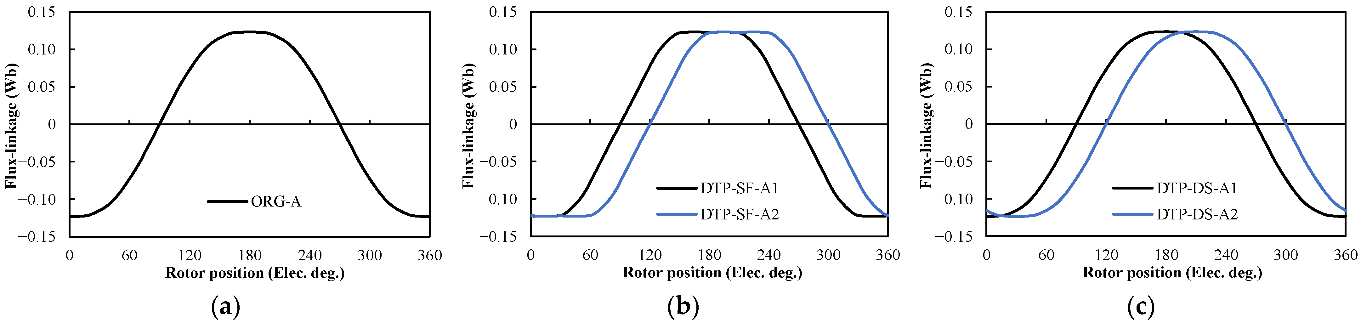
Figure 13.
Phase flux-linkages of different winding configurations under OC condition: (a) ORG; (b) DTP-SF; (c) DTP-DS.
Figure 13.
Phase flux-linkages of different winding configurations under OC condition: (a) ORG; (b) DTP-SF; (c) DTP-DS.
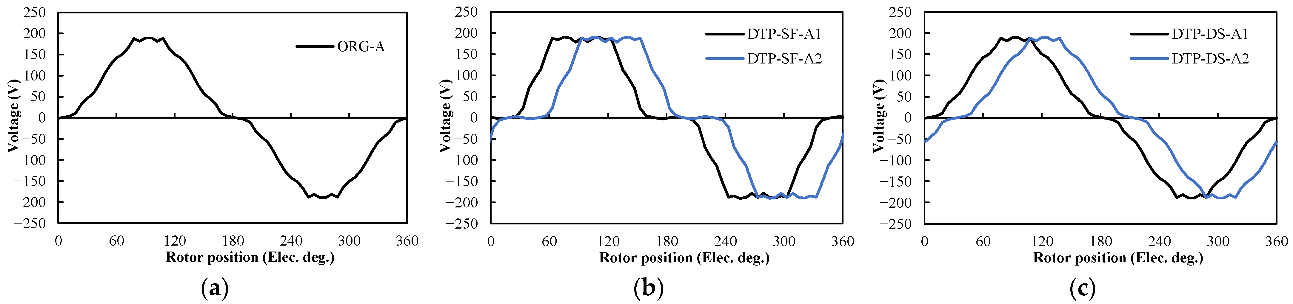
Figure 14.
Phase back EMF of different winding configurations at 3000× g rpm: (a) ORG; (b) DTP-SF; (c) DTP-DS.
Figure 14.
Phase back EMF of different winding configurations at 3000× g rpm: (a) ORG; (b) DTP-SF; (c) DTP-DS.
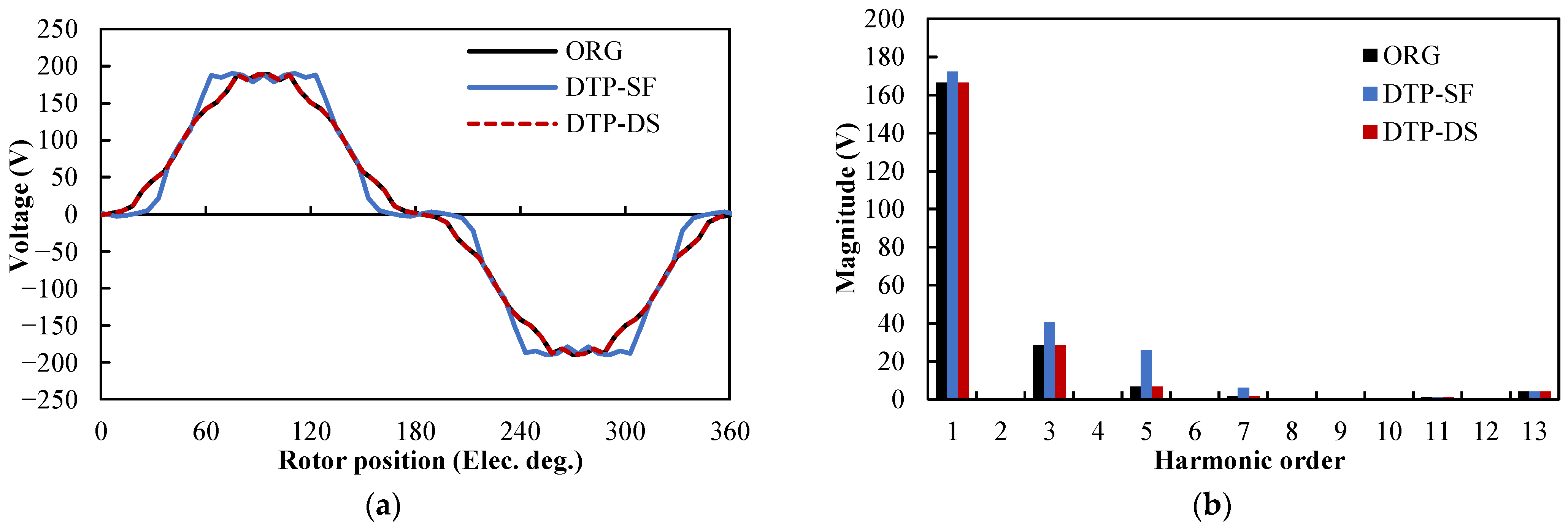
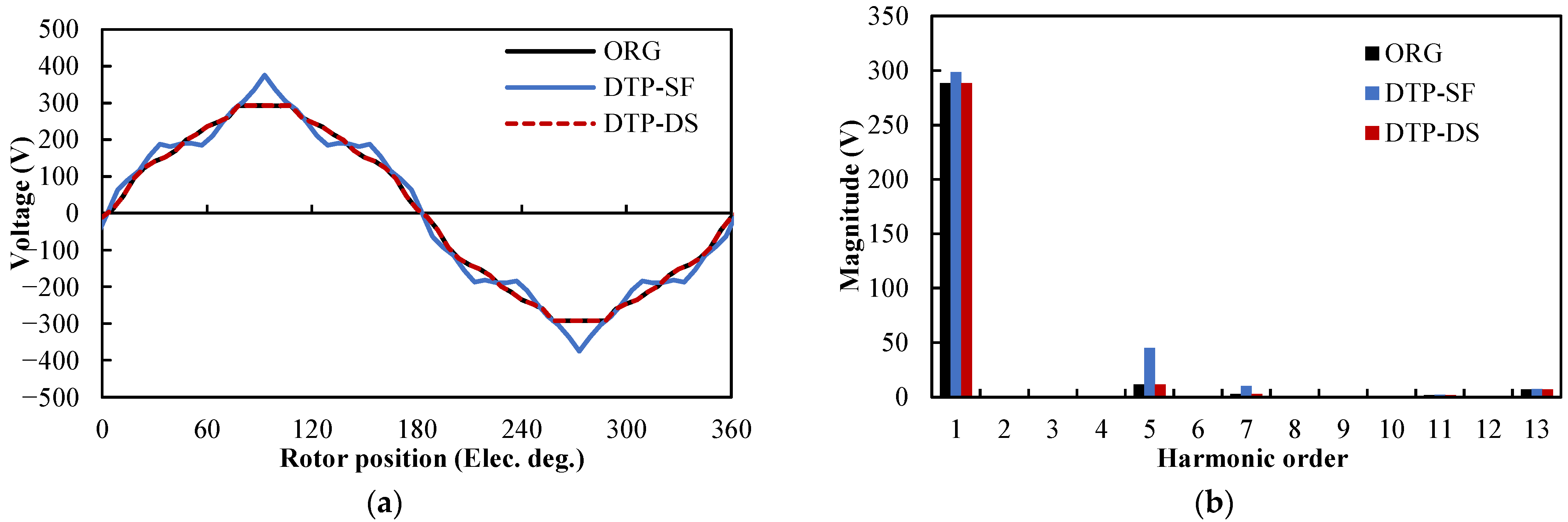
Figure 15.
Phase back EMFs of different winding configurations at 3000× g rpm: (a) waveforms; (b) spectra.
Figure 15.
Phase back EMFs of different winding configurations at 3000× g rpm: (a) waveforms; (b) spectra.
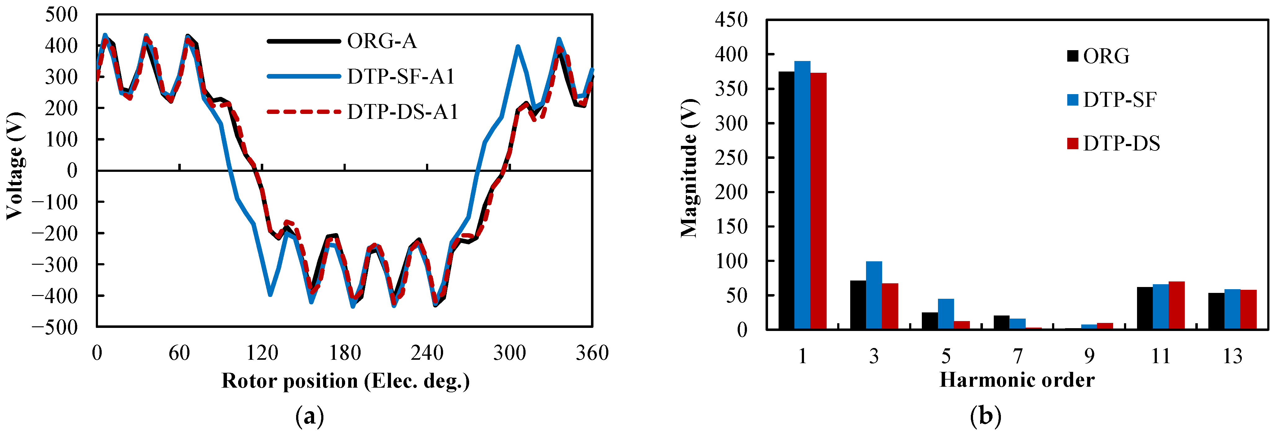
Figure 16.
Line-to-line back EMFs of different winding configurations at 3000× g rpm: (a) waveforms; (b) spectra.
Figure 16.
Line-to-line back EMFs of different winding configurations at 3000× g rpm: (a) waveforms; (b) spectra.
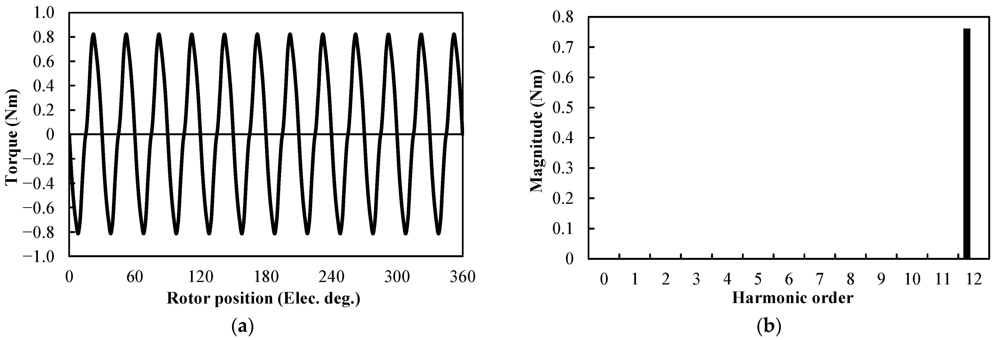
Figure 17.
Cogging torque of Prius 2010 machine: (a) waveform; (b) spectrum.
Figure 17.
Cogging torque of Prius 2010 machine: (a) waveform; (b) spectrum.
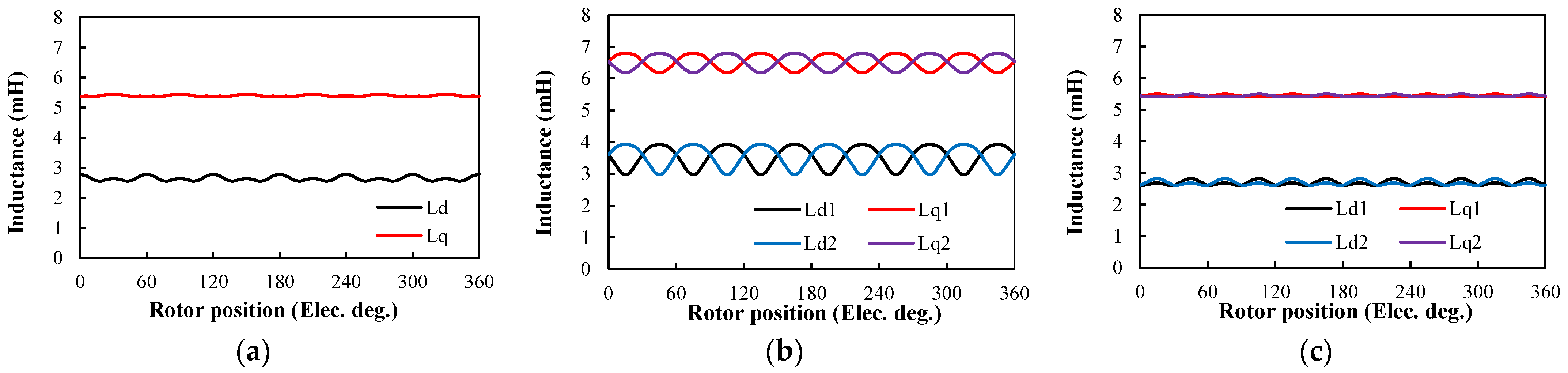
Figure 18.
d- and q-axis inductances of different winding configurations at OC: (a) ORG; (b) DTP-SF; (c) DTP-DS.
Figure 18.
d- and q-axis inductances of different winding configurations at OC: (a) ORG; (b) DTP-SF; (c) DTP-DS.
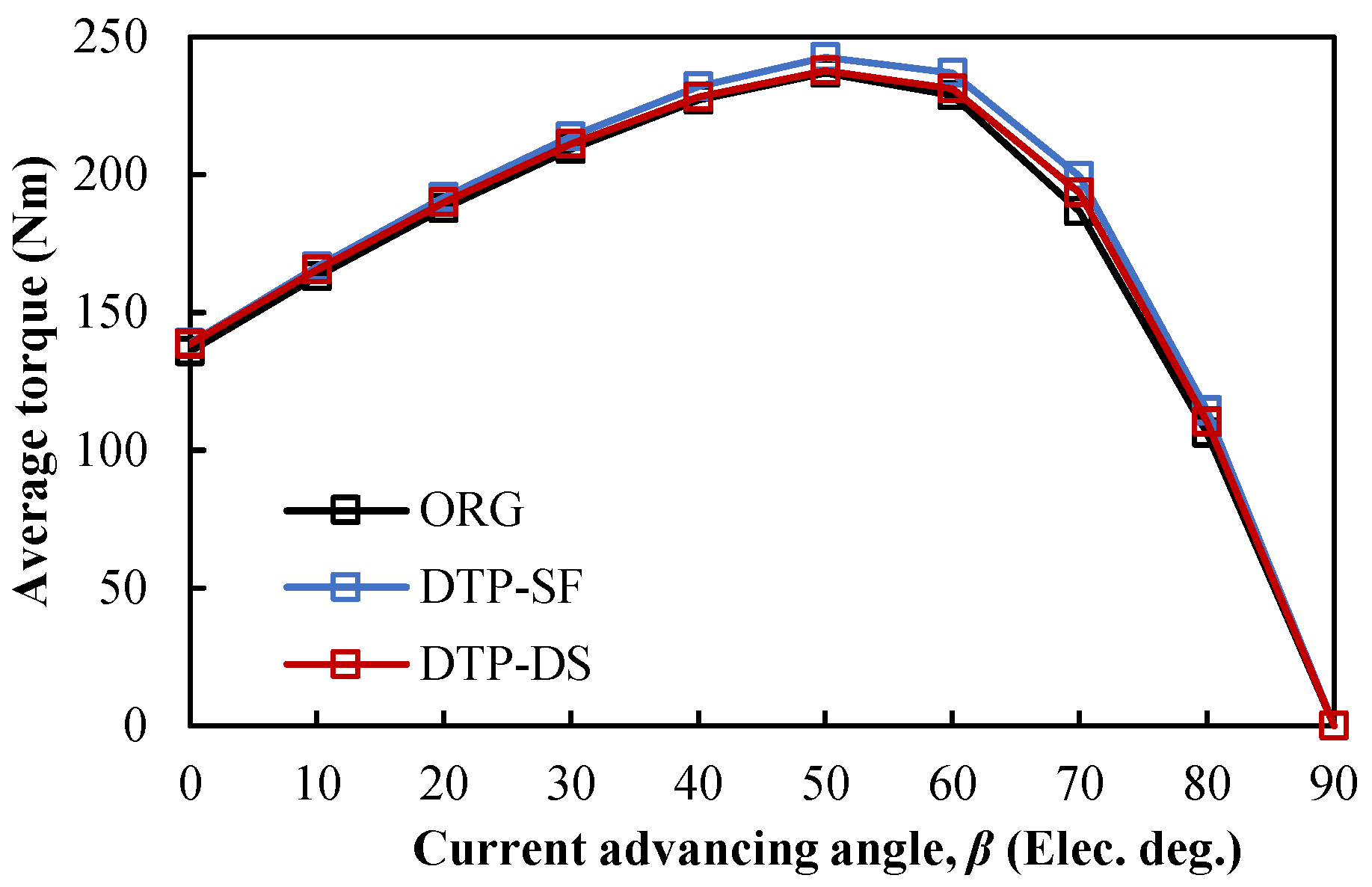
Figure 19.
Average torque-current advancing angle characteristics of different winding configurations.
Figure 19.
Average torque-current advancing angle characteristics of different winding configurations.
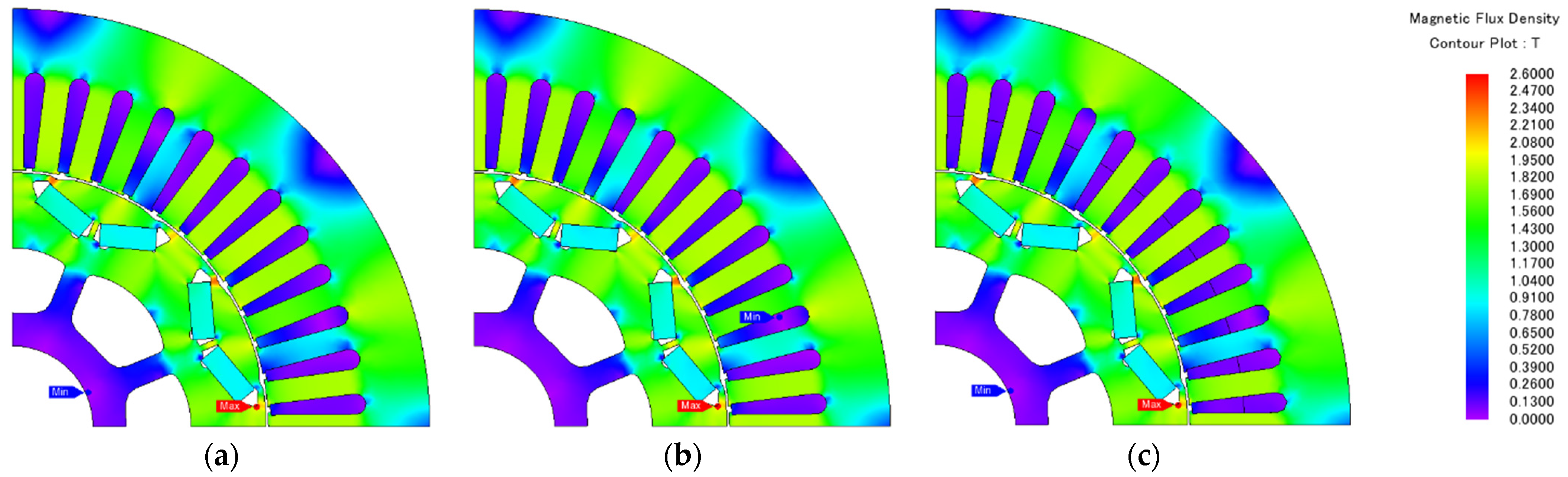
Figure 20.
Flux density distributions of different winding configurations at IA = 236 Apk, β = 0°: (a) ORG; (b) DTP-SF; (c) DTP-DS.
Figure 20.
Flux density distributions of different winding configurations at IA = 236 Apk, β = 0°: (a) ORG; (b) DTP-SF; (c) DTP-DS.
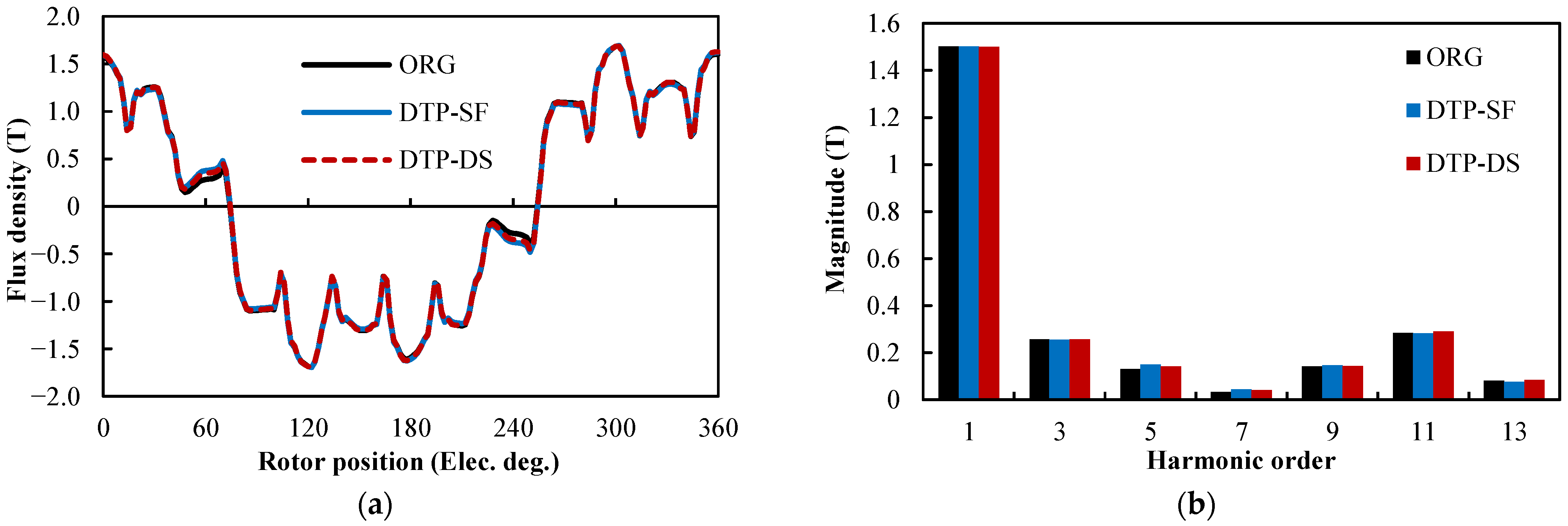
Figure 21.
Air-gap flux density distributions of different winding configurations at IA = 236 Apk, β = 0°: (a) waveforms; (b) spectra.
Figure 21.
Air-gap flux density distributions of different winding configurations at IA = 236 Apk, β = 0°: (a) waveforms; (b) spectra.
Figure 22.
Phase back EMFs of different winding configurations @IA = 236 Apk, β = 0°: (a) waveforms; (b) spectra.
Figure 22.
Phase back EMFs of different winding configurations @IA = 236 Apk, β = 0°: (a) waveforms; (b) spectra.
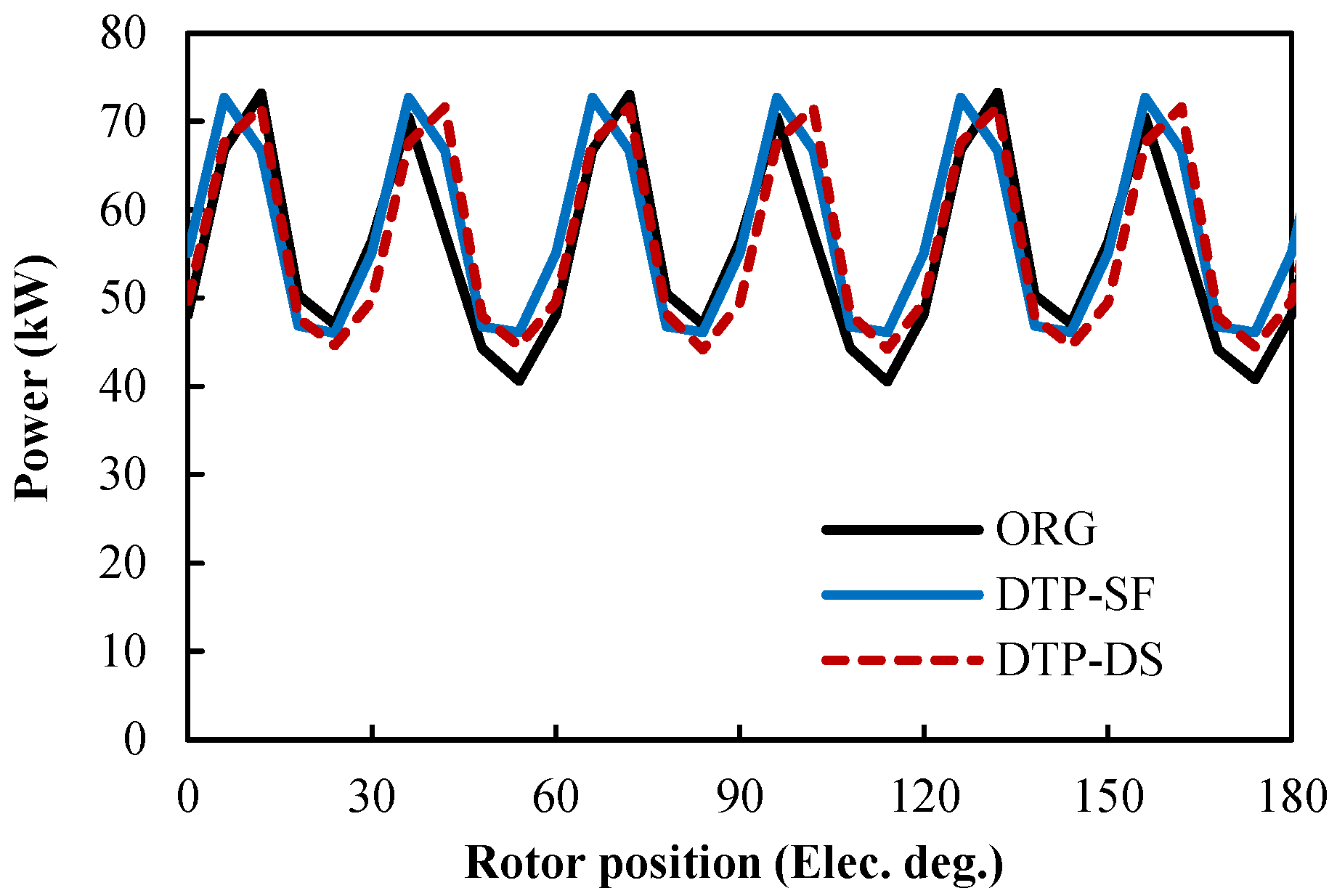
Figure 23.
Input power of different winding configurations @IA = 236 Apk, β = 0°.
Figure 23.
Input power of different winding configurations @IA = 236 Apk, β = 0°.
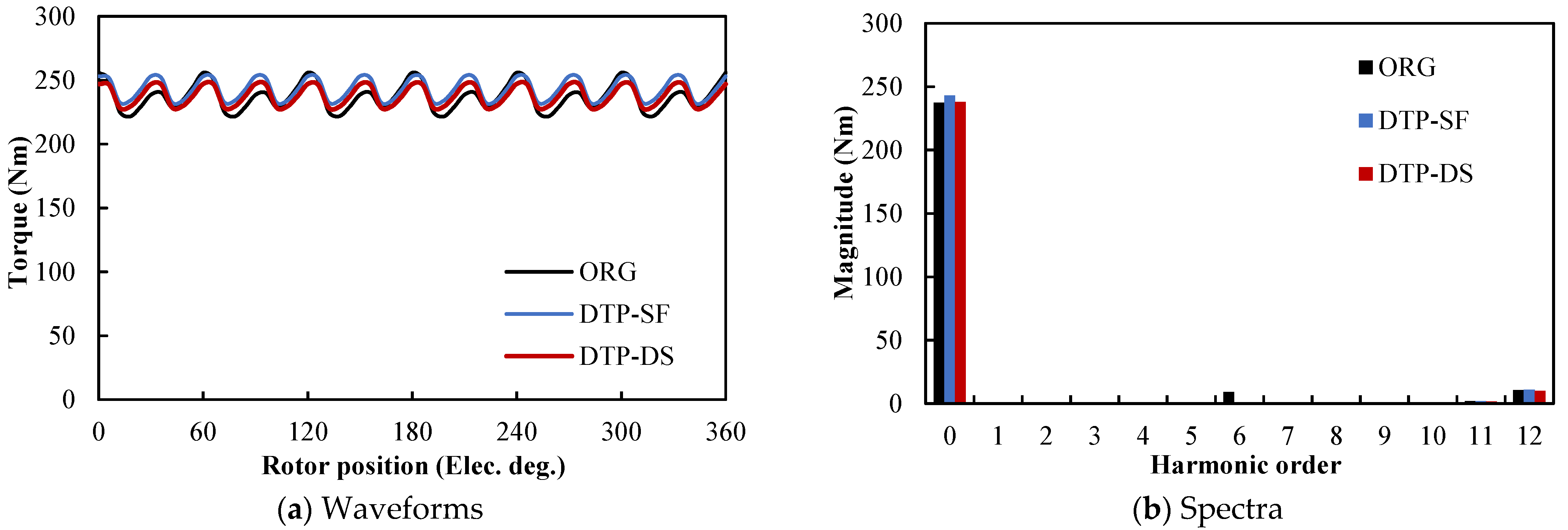
Figure 24.
Instantaneous torque performance of different winding configurations under maximum torque condition: (a) waveforms; (b) spectra.
Figure 24.
Instantaneous torque performance of different winding configurations under maximum torque condition: (a) waveforms; (b) spectra.
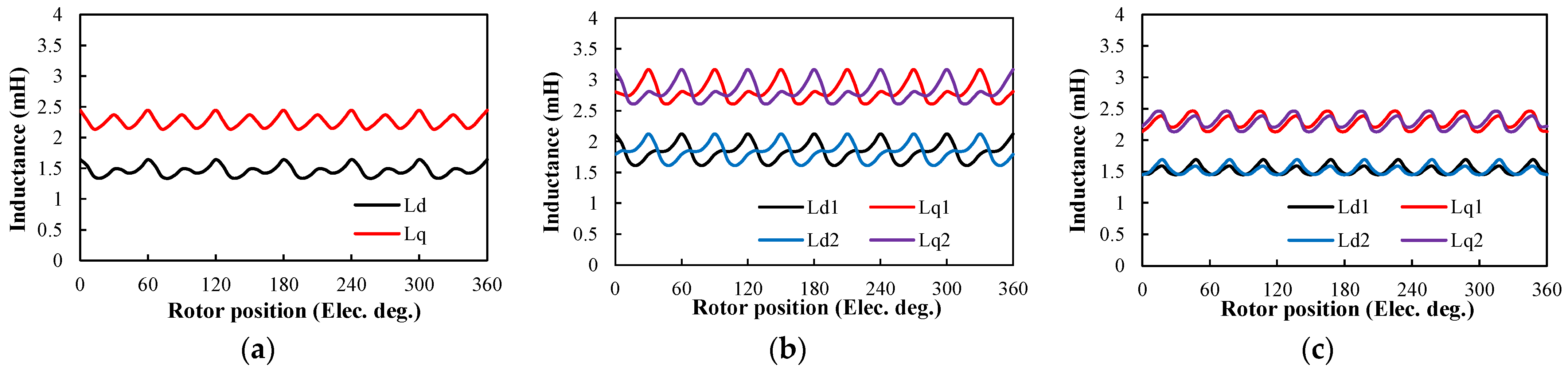
Figure 25.
d- and q-axis inductances of different winding configurations at maximum torque condition: (a) ORG; (b) DTP-SF; (c) DTP-DS.
Figure 25.
d- and q-axis inductances of different winding configurations at maximum torque condition: (a) ORG; (b) DTP-SF; (c) DTP-DS.
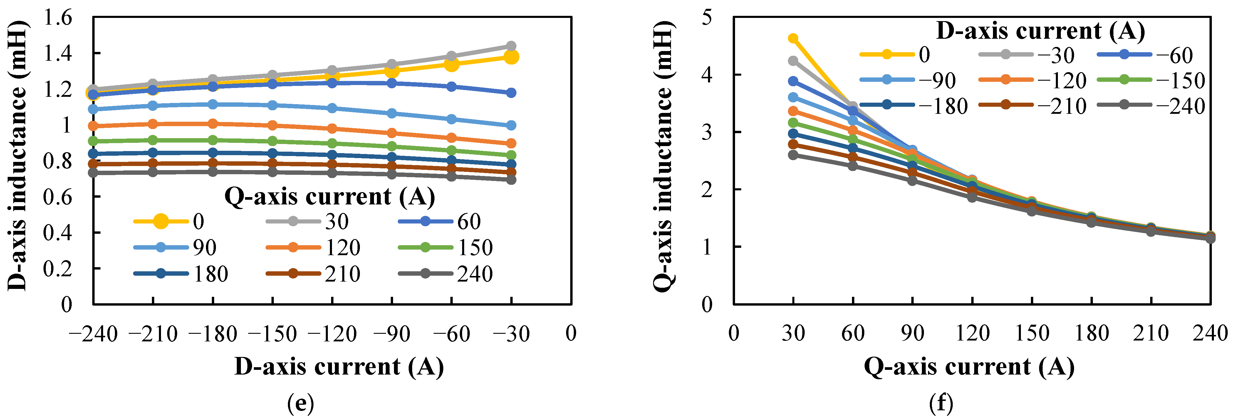
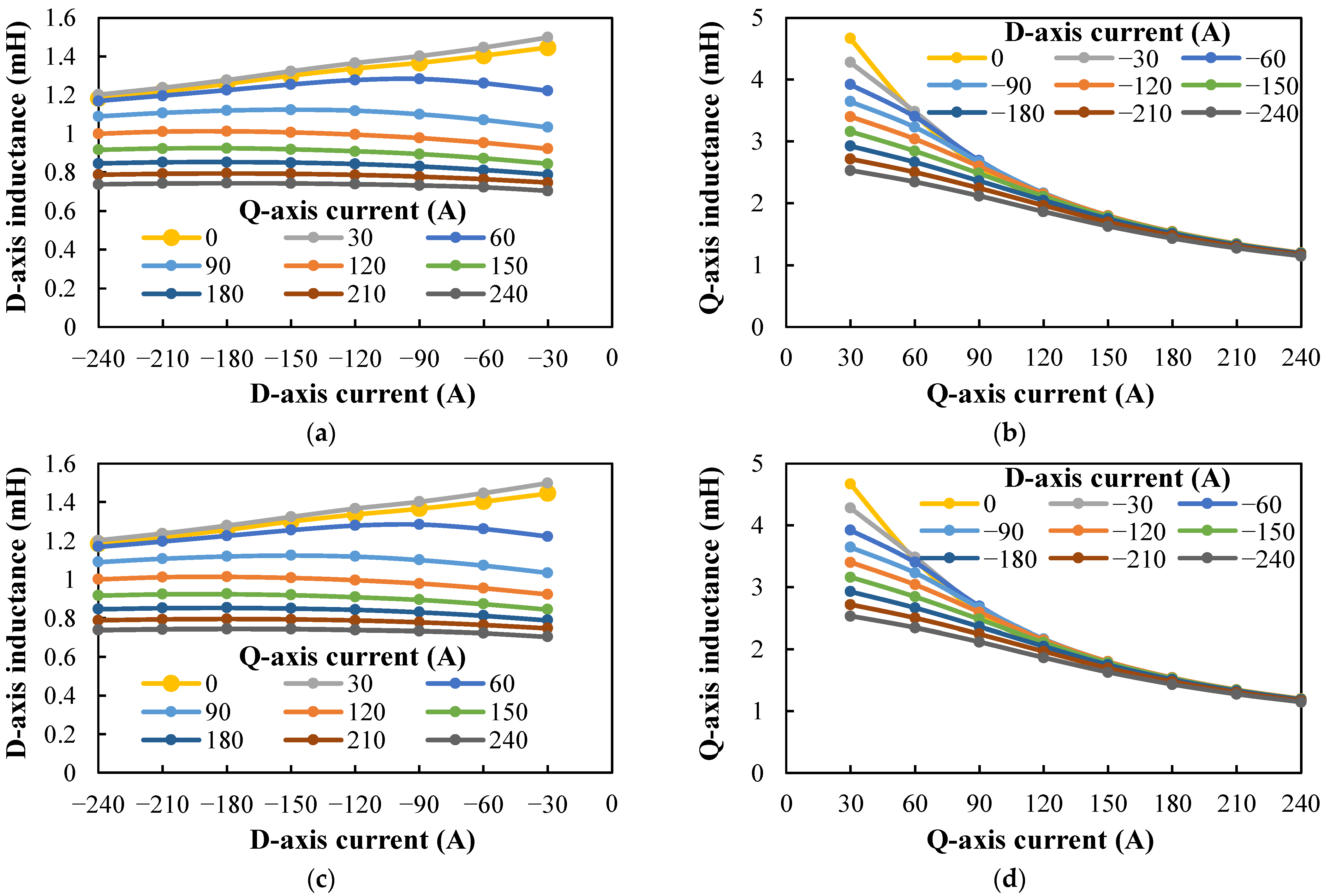
Figure 26.
Variations of d- and q-axis inductances with different winding configurations and different d- and q-axis current combinations: (a) ORG: d-axis inductance; (b) ORG: q-axis inductance; (c) DTP-SF: d-axis inductance; (d) DTP-SF: q-axis inductance; (e) DTP-DS: d-axis inductance; (f) DTP-DS: q-axis inductance.
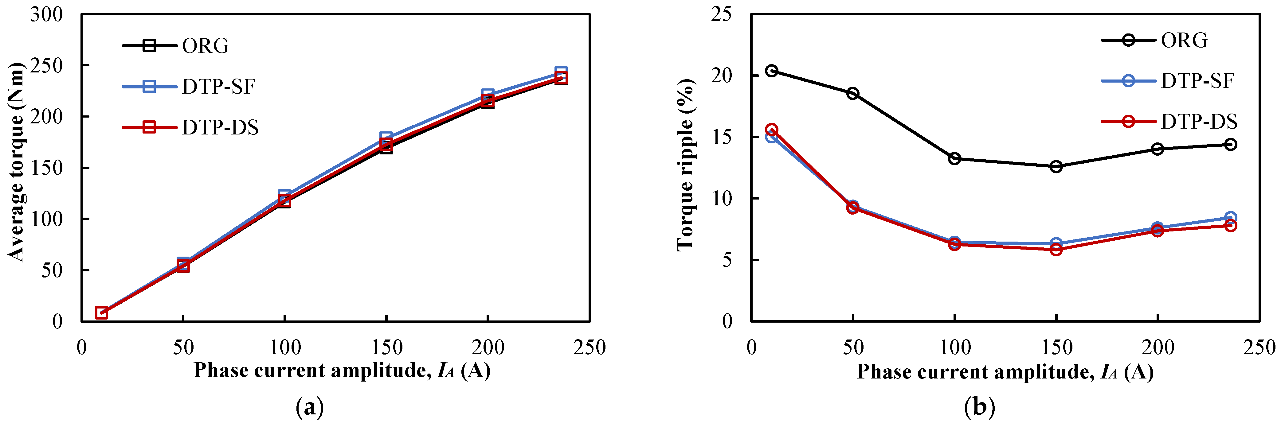
Figure 27.
Torque-current amplitude characteristics of different winding configurations with MTPA strategy: (a) average torque; (b) torque ripple.
Figure 27.
Torque-current amplitude characteristics of different winding configurations with MTPA strategy: (a) average torque; (b) torque ripple.
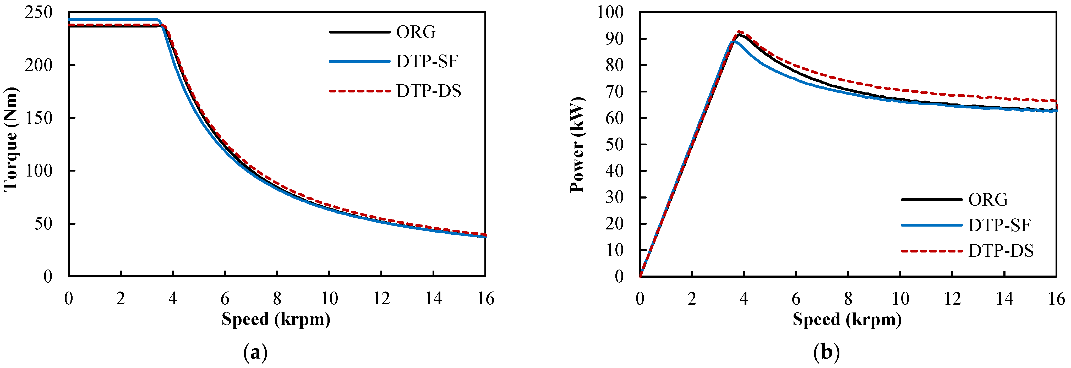
Figure 28.
Torque– and power–speed envelopes of different winding configurations: (a) torque–speed envelope; (b) power–speed envelope.
Figure 28.
Torque– and power–speed envelopes of different winding configurations: (a) torque–speed envelope; (b) power–speed envelope.
Figure 29.
d- and q-axis currents of different winding configurations over entire speed range: (a) ORG; (b) DTP-SF; (c) DTP-DS.
Figure 29.
d- and q-axis currents of different winding configurations over entire speed range: (a) ORG; (b) DTP-SF; (c) DTP-DS.
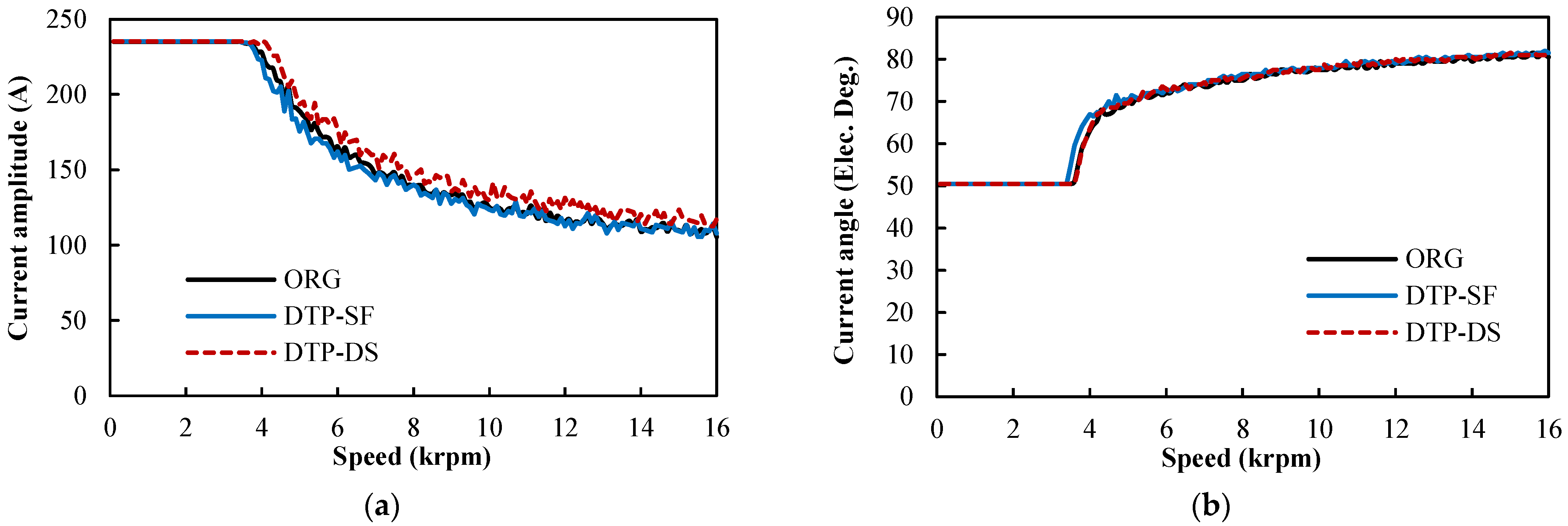
Figure 30.
Amplitudes and current angles of phase currents of different winding configurations over entire speed range: (a) amplitudes; (b) current angles.
Figure 30.
Amplitudes and current angles of phase currents of different winding configurations over entire speed range: (a) amplitudes; (b) current angles.
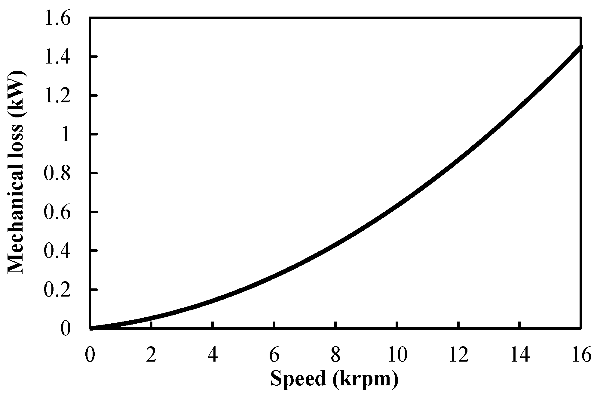
Figure 31.
Variation of mechanical loss with speed [
40].
Figure 31.
Variation of mechanical loss with speed [
40].
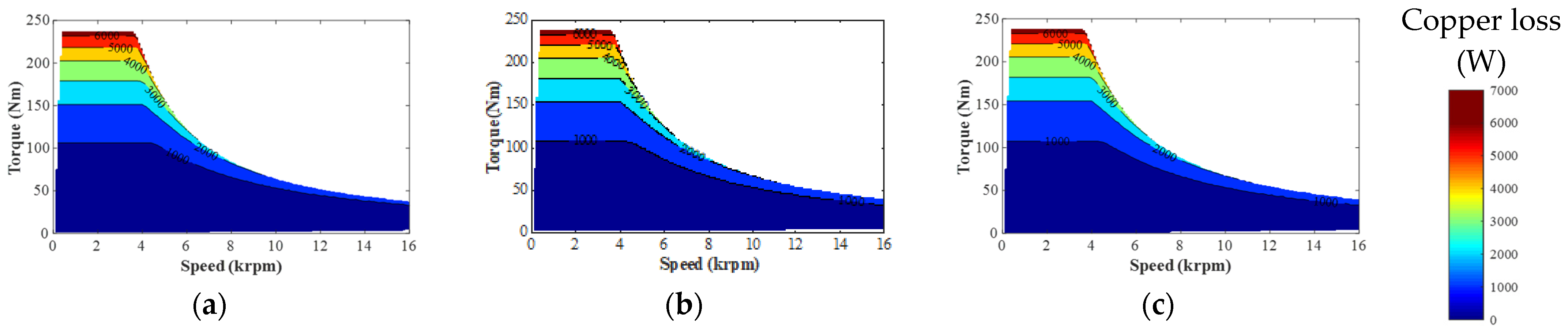
Figure 32.
Copper loss maps of different winding configurations. (a) ORG; (b) DTP-SF; (c) DTP-DS.
Figure 32.
Copper loss maps of different winding configurations. (a) ORG; (b) DTP-SF; (c) DTP-DS.
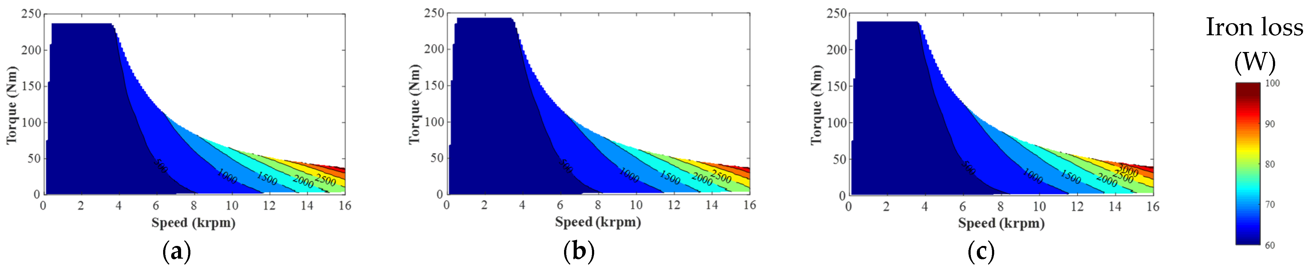
Figure 33.
Iron loss maps of different winding configurations: (a) ORG; (b) DTP-SF; (c) DTP-DS.
Figure 33.
Iron loss maps of different winding configurations: (a) ORG; (b) DTP-SF; (c) DTP-DS.
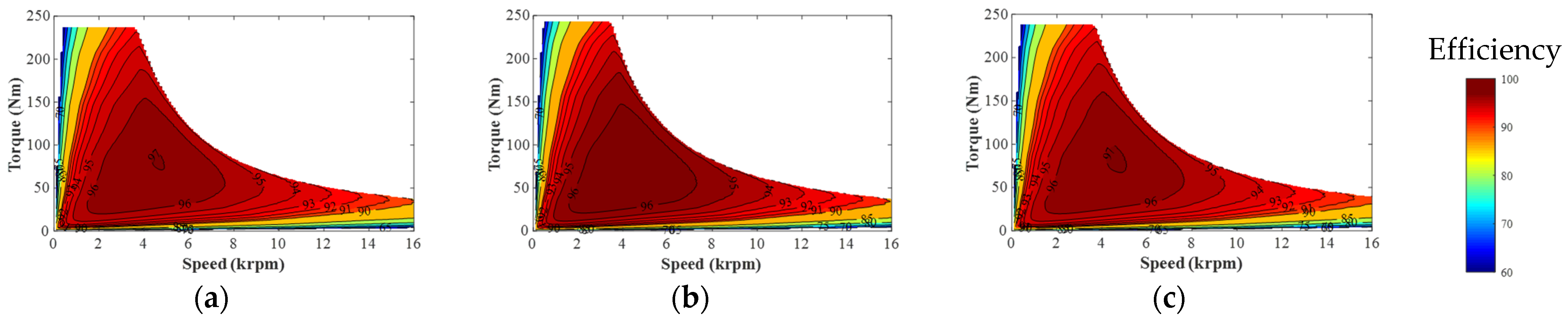
Figure 34.
Efficiency maps of different winding configurations: (a) ORG; (b) DTP-SF; (c) DTP-DS.
Figure 34.
Efficiency maps of different winding configurations: (a) ORG; (b) DTP-SF; (c) DTP-DS.
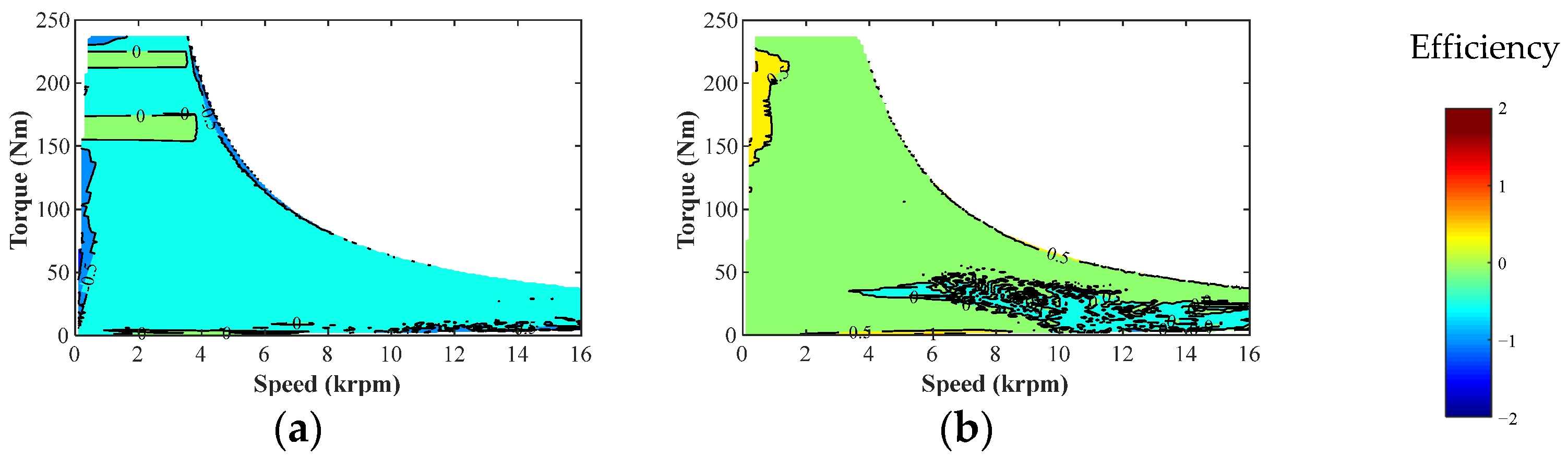
Figure 35.
Differences between efficiency maps of DTP and ORG winding configurations: (a) DTP-SF; (b) DTP-DS.
Figure 35.
Differences between efficiency maps of DTP and ORG winding configurations: (a) DTP-SF; (b) DTP-DS.
Figure 36.
Winding layouts of remaining winding set in DTP machines: (a) DTP-SF; (b) DTP-DS.
Figure 36.
Winding layouts of remaining winding set in DTP machines: (a) DTP-SF; (b) DTP-DS.
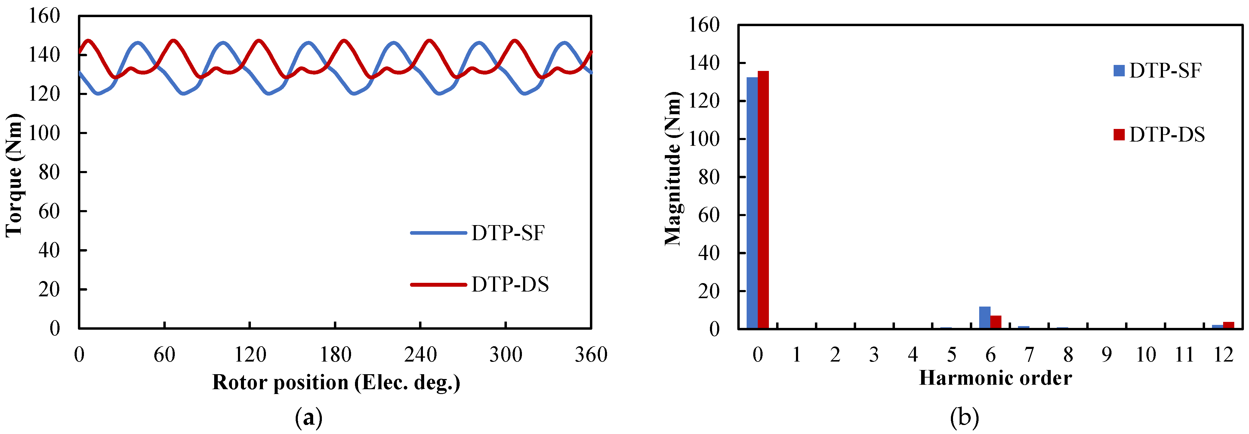
Figure 37.
Instantaneous torque characteristics of different winding configurations under three-phase OC maximum torque condition: (a) waveforms; (b) spectra.
Figure 37.
Instantaneous torque characteristics of different winding configurations under three-phase OC maximum torque condition: (a) waveforms; (b) spectra.
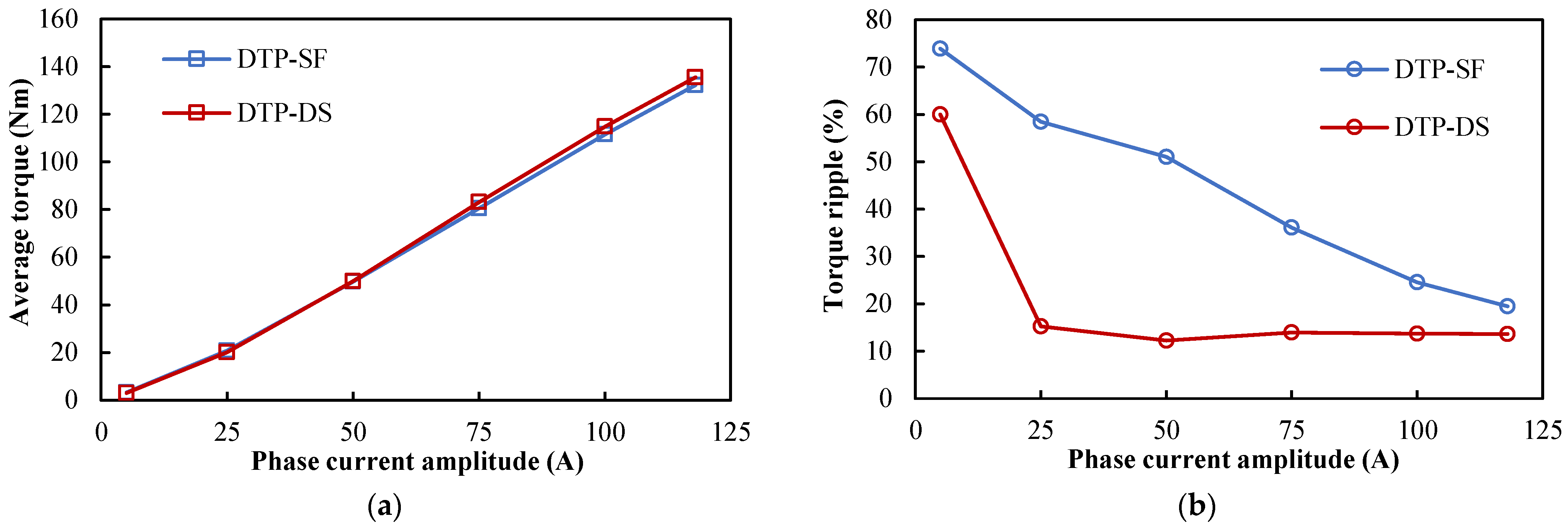
Figure 38.
Torque-current amplitude characteristics of different winding configurations with MTPA strategy under the three-phase OC condition: (a) average torque; (b) torque ripple.
Figure 38.
Torque-current amplitude characteristics of different winding configurations with MTPA strategy under the three-phase OC condition: (a) average torque; (b) torque ripple.
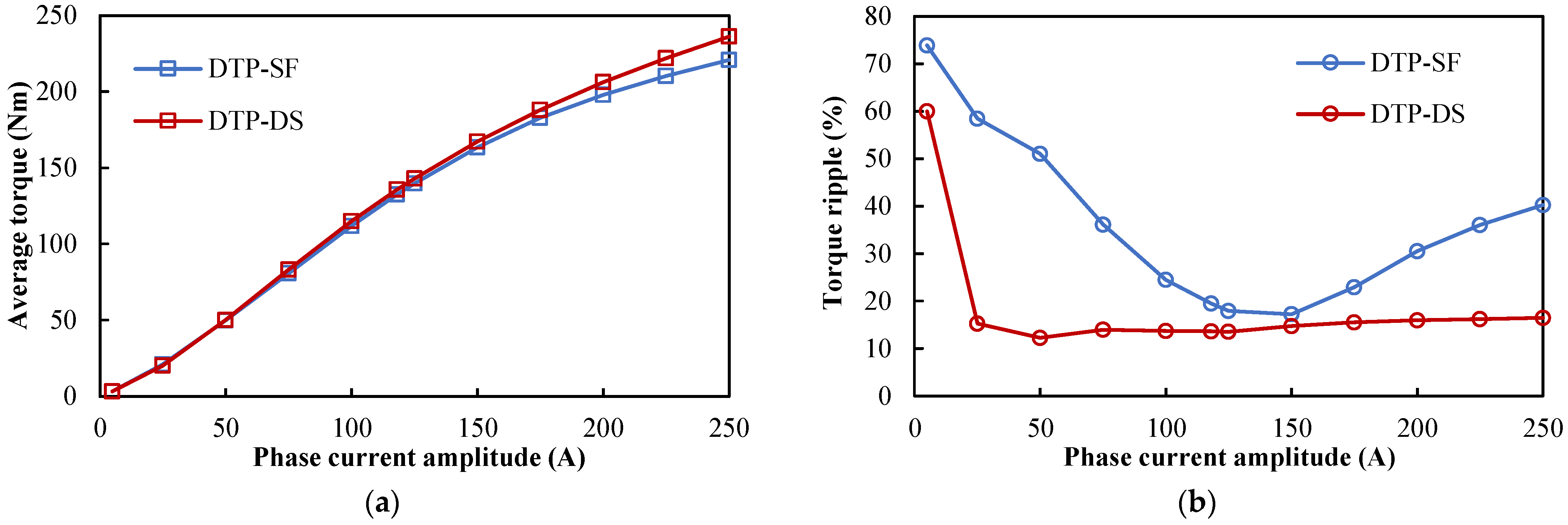
Figure 39.
Torque-current amplitude characteristics of different winding configurations with the MTPA strategy under the three-phase OC condition considering over-loading: (a) average torque; (b) torque ripple.
Figure 39.
Torque-current amplitude characteristics of different winding configurations with the MTPA strategy under the three-phase OC condition considering over-loading: (a) average torque; (b) torque ripple.
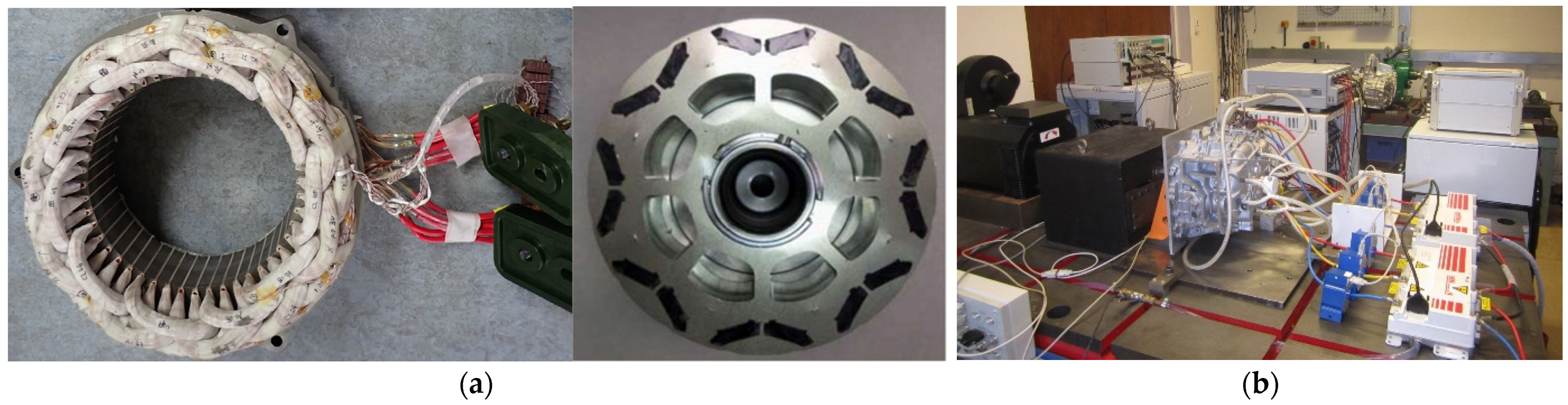
Figure 40.
Photos of prototype and test rig: (a) prototype; (b) test rig.
Figure 40.
Photos of prototype and test rig: (a) prototype; (b) test rig.
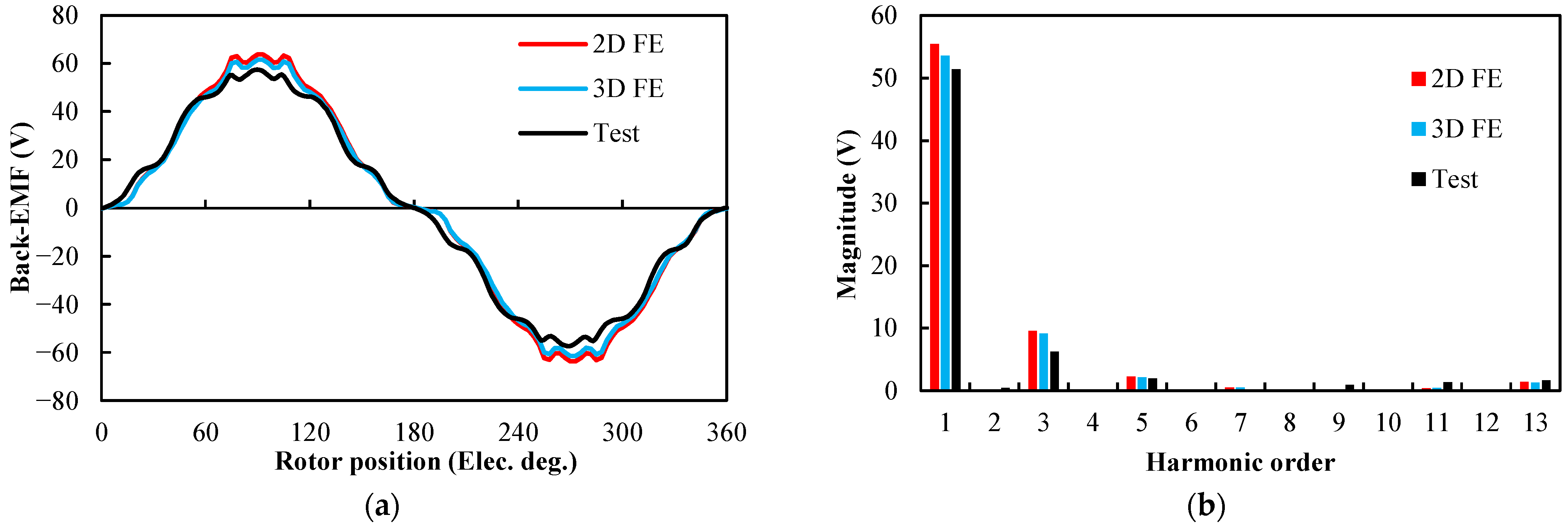
Figure 41.
Phase back EMF comparison between FE and measured results at 1000 rpm: (a) waveforms; (b) spectra.
Figure 41.
Phase back EMF comparison between FE and measured results at 1000 rpm: (a) waveforms; (b) spectra.
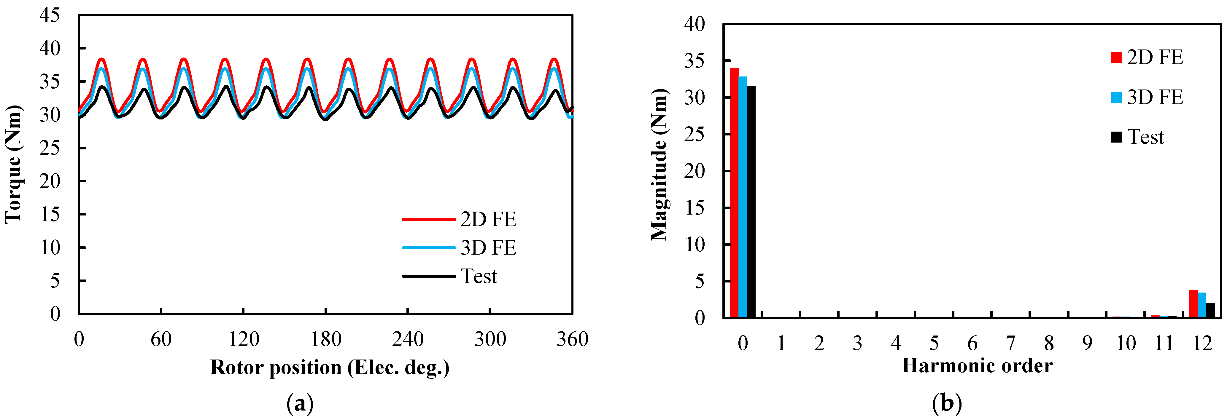
Figure 42.
Instantaneous torque comparison between FE and measured results @20 Apk phase currents: (a) waveforms; (b) spectra.
Figure 42.
Instantaneous torque comparison between FE and measured results @20 Apk phase currents: (a) waveforms; (b) spectra.
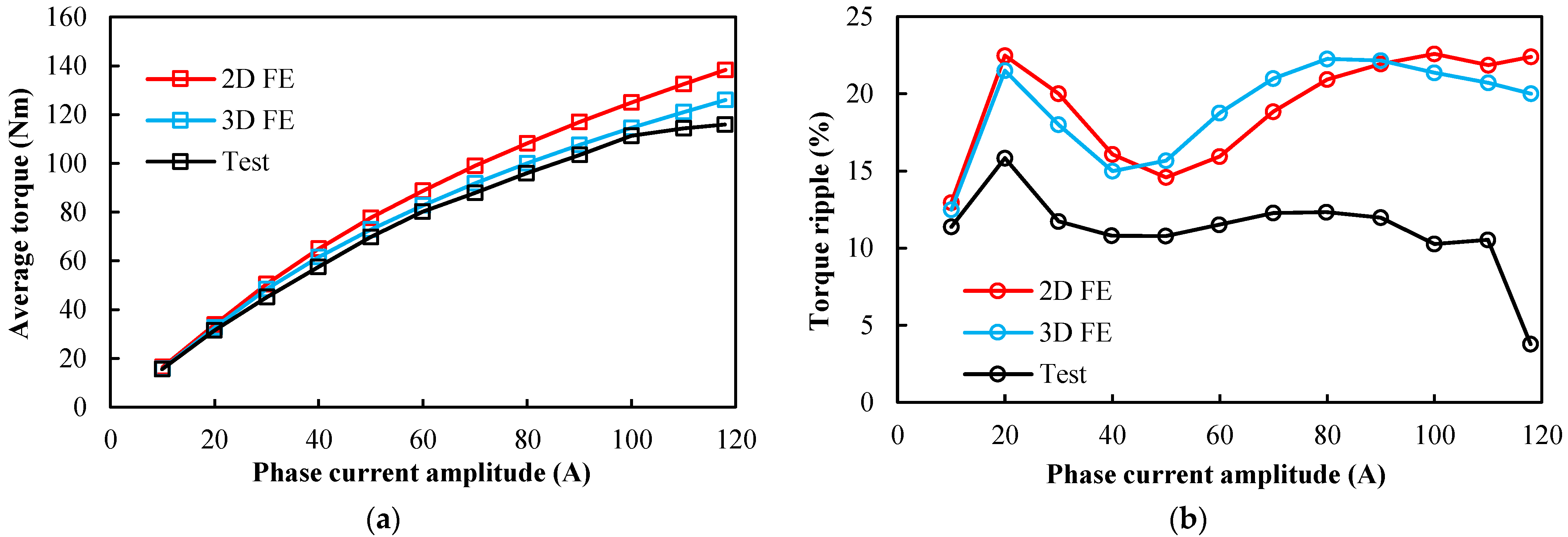
Figure 43.
Torque-current amplitude characteristics comparison between FE and measured results with the Id = 0 control strategy: (a) Average torque; (b) Torque ripple.
Figure 43.
Torque-current amplitude characteristics comparison between FE and measured results with the Id = 0 control strategy: (a) Average torque; (b) Torque ripple.
Table 1.
Design specifications of Toyota Prius 2010 IPM machine.
Table 1.
Design specifications of Toyota Prius 2010 IPM machine.
| Number of Stator Slots | 48 | Number of Rotor Poles | 8 |
|---|
| Stator OD, mm | 264 | Rotor OD, mm | 160.44 |
| Stator ID, mm | 161.9 | Rotor lamination ID, mm | 51 |
| Stator stack length, mm | 50.8 | Lamination thickness, mm | 0.305 |
| Slot depth, mm | 30.9 | Slot opening, mm | 1.88 |
| Phase resistance, Ohm | 0.077 | Magnet dimensions, mm | 49.3 × 17.88 × 7.16 |
Table 2.
Specifications of different winding configurations.
Table 3.
Estimated key parameters of different winding configurations.
Table 3.
Estimated key parameters of different winding configurations.
| | ORG | DTP-SF | DTP-DS |
|---|
| Total axial length (mm) | 113.9 | 126.51 | 113.9 |
| Phase resistance (Ohm) | 0.077 | 0.174363 | 0.154 |
Table 4.
Winding factors of different winding configurations.
Table 4.
Winding factors of different winding configurations.
| | ORG | DTP-SF | DTP-DS |
|---|
| Distribution factor, kd | 1 | 1 | 1 |
| Pitch factor, kp | 0.966 | 1 | 0.966 |
| Winding factor, kw | 0.966 | 1 | 0.966 |
Table 5.
Comparison of average torque-current advancing angle characteristics of different winding configurations.
Table 5.
Comparison of average torque-current advancing angle characteristics of different winding configurations.
| | ORG | DTP-SF | DTP-DS |
|---|
| Current Advancing Angle, β (ED) | Average Torque (Nm) | Average Torque (Nm) | Improvement
(% Compared with ORG) | Average Torque (Nm) | Improvement
(% Compared with ORG) |
|---|
| 0 | 135.82 | 138.74 | 2.15 | 138.67 | 2.10 |
| 10 | 162.93 | 166.46 | 2.17 | 165.63 | 1.66 |
| 20 | 187.70 | 191.73 | 2.15 | 190.03 | 1.24 |
| 30 | 209.31 | 213.77 | 2.14 | 211.08 | 0.85 |
| 40 | 227.22 | 232.12 | 2.16 | 228.23 | 0.44 |
| 50 | 236.98 | 242.80 | 2.45 | 237.75 | 0.33 |
| 60 | 228.95 | 237.02 | 3.53 | 231.26 | 1.01 |
| 70 | 186.77 | 199.38 | 6.75 | 193.43 | 3.57 |
| 80 | 106.29 | 114.43 | 7.66 | 110.36 | 3.83 |
| 90 | 0.01 | 0.02 | - | 0.05 | - |
Table 6.
Comparison of instantaneous torque performance of different winding configurations under maximum torque condition.
Table 6.
Comparison of instantaneous torque performance of different winding configurations under maximum torque condition.
| | ORG | DTP-SF | DTP-DS |
|---|
| Average torque | 236.98 | 242.80 | 237.75 |
| Improvement (% compared with ORG) | - | 2.45 | 0.33 |
| Torque ripple (Nm) | 34.11 | 20.46 | 18.54 |
| Torque ripple (%) | 14.39 | 8.43 | 7.80 |
Table 7.
Comparison of torque-current amplitude characteristics of different winding configurations with the MTPA strategy.
Table 7.
Comparison of torque-current amplitude characteristics of different winding configurations with the MTPA strategy.
| IA (A) | | ORG | DTP-SF | DTP-DS |
|---|
| 10 | Average torque (Nm) | 8.25 | 8.55 | 8.25 |
| Improvement (% compared with ORG) | | 3.73 | −0.02 |
| Torque ripple (Nm) | 1.68 | 1.28 | 1.29 |
| Torque ripple (%) | 20.37 | 15.00 | 15.59 |
| 50 | Average torque | 54.01 | 56.52 | 54.17 |
| Improvement (% compared with ORG) | | 4.64 | 0.29 |
| Torque ripple (Nm) | 10.02 | 5.29 | 5.00 |
| Torque ripple (%) | 18.55 | 9.36 | 9.23 |
| 100 | Average torque | 116.66 | 122.44 | 117.95 |
| Improvement (% compared with ORG) | | 4.95 | 1.10 |
| Torque ripple (Nm) | 15.43 | 7.84 | 7.39 |
| Torque ripple (%) | 13.22 | 6.41 | 6.26 |
| 150 | Average torque | 169.44 | 178.90 | 172.86 |
| Improvement (% compared with ORG) | | 5.59 | 2.02 |
| Torque ripple (Nm) | 21.32 | 11.27 | 10.08 |
| Torque ripple (%) | 12.58 | 6.30 | 5.83 |
| 200 | Average torque | 213.38 | 221.15 | 215.64 |
| Improvement (% compared with ORG) | | 3.64 | 1.06 |
| Torque ripple (Nm) | 29.91 | 16.83 | 15.88 |
| Torque ripple (%) | 14.02 | 7.61 | 7.37 |
| 236 | Average torque | 236.98 | 242.80 | 237.75 |
| Improvement (% compared with ORG) | | 2.45 | 0.33 |
| Torque ripple (Nm) | 34.11 | 20.46 | 18.54 |
| Torque ripple (%) | 14.39 | 8.43 | 7.80 |
Table 8.
Loss and efficiency of different winding configurations under maximum torque condition.
Table 8.
Loss and efficiency of different winding configurations under maximum torque condition.
| | ORG | DTP-SF | DTP-DS |
|---|
| Speed (rpm) | 3000 | 3000 | 3000 |
| Average torque (Nm) | 236.98 | 242.80 | 237.75 |
| Copper loss (W) | 6432.89 | 7283.49 | 6432.89 |
| Iron loss (W) | 358.34 | 368.14 | 365.40 |
| PM eddy loss (W) | 94.58 | 46.24 | 51.28 |
| Mechanical loss (W) | 93.20 | 93.20 | 93.20 |
| Output power (W) | 74449.61 | 76276.54 | 74690.46 |
| Total loss (W) | 6979.01 | 7791.07 | 6942.77 |
| Input power (W) | 81428.62 | 84067.61 | 81633.23 |
| Efficiency (%) | 91.43% | 90.73% | 91.50% |
Table 9.
Comparison of instantaneous torque characteristics of different winding configurations under the three-phase OC maximum torque condition.
Table 9.
Comparison of instantaneous torque characteristics of different winding configurations under the three-phase OC maximum torque condition.
| | DTP-SF | DTP-DS |
|---|
| Average torque (Nm) | 132.35 | 135.56 |
| Torque ripple (Nm) | 25.76 | 18.49 |
| Torque ripple (%) | 19.46 | 13.64 |
Table 10.
Loss and efficiency of different winding configurations under three-phase OC maximum torque condition.
Table 10.
Loss and efficiency of different winding configurations under three-phase OC maximum torque condition.
| | DTP-SF | DTP-DS |
|---|
| Speed (rpm) | 3000 | 3000 |
| Average torque (Nm) | 132.35 | 135.56 |
| Copper loss (W) | 7283.49 | 6432.89 |
| Iron loss (W) | 245.53 | 247.14 |
| PM eddy loss (W) | 230.49 | 44.11 |
| Mechanical loss (W) | 93.20 | 93.20 |
| Output power (W) | 41578.68 | 42587.43 |
| Total loss (W) | 7852.70 | 6817.34 |
| Input power (W) | 49431.68 | 49404.77 |
| Efficiency (%) | 84.11 | 86.20 |
Table 11.
Pros and cons of different winding configurations under maximum torque conditions.
Table 11.
Pros and cons of different winding configurations under maximum torque conditions.
| | ORG | DTP-SF | DTP-DS |
|---|
| Pros | | Highest torque under healthy condition Lower torque pulsation under healthy condition (Compare with ORG) Ability to run under three-phase OC condition
| Slightly higher torque under healthy condition (Compare with ORG) Lower torque pulsation under healthy condition (Compare with ORG) Slightly higher efficiency (Compare with ORG) Highest torque under high-speed healthy condition Ability to run under three-phase OC condition Higher average torque and lower torque pulsation under three-phase OC condition (Compare with DTP-SF)
|
| Cons | | Complex winding connections Complex drive system Largest winding usage Worst efficiency performance Lowest torque under high-speed healthy condition Worse torque performance under three-phase OC condition (Compare with DTP-DS)
| |


 ,
, 


