Article

The Optimal Deployment of the Entry and Exit Gates of Electric Vehicles Wireless Charging Transmitters on Highways

by
Mohammed Bourzik
1,*,
Hassane Elbaz
1 and
Ahmed Elhilali Alaoui
2
1
Modelling and Scientific Computing Laboratory, Faculty of Science and Technology of Fez, Fez 2202, Morocco
2
Digital Engineering and Artificial Intelligence School, EuroMed University of Fes, Fez 2202, Morocco
*
Author to whom correspondence should be addressed.
World Electr. Veh. J. 2022, 13(12), 227; https://doi.org/10.3390/wevj13120227
Submission received: 25 October 2022 / Revised: 10 November 2022 / Accepted: 22 November 2022 / Published: 28 November 2022

Abstract

:
Dynamic wireless charging (DWC) facilitates the travel of electric vehicles (EVs) on highways because it can charge EVs without contact and it does not have a recharging time as it can charge vehicles in motion by a set of power transmitters on the road. This work considers a highway road with DWC and a fleet of electric vehicles with heterogeneous batteries to begin a trip from the origin of the highway noted by O to the destination noted by S. As the usage of DWC is not free, this study seeks to install entry gates to the DWC if the vehicles need to charge their batteries and exit gates to the main road if the vehicles wish to stop the recharge. For this purpose, the first objective is to minimize the usage cost paid by each vehicle type to use the DWC during the trip on the highway. The second objective is to find the lower installation cost of the gates on the road. This work proposes to model the problem as a mathematical problem and validate it with the CPLEX optimizer using limited instances and, finally, solves the problem using the non-dominated sorting genetic algorithm (NSGA-II).

1. Introduction

Nowadays, the use of combustion vehicles is expensive due to the increased fuel prices; for this reason, the world is orienting towards using electric vehicles (EVs).
An electric vehicle is a type of vehicle that operates on electricity by exploiting the technology of a battery or fuel cell. It is not a new technology, as the first experimental electric car was produced in 1935. However, it did not return to the market until 2000. This return was motivated by the political will to combat global warming and preserve the environment. Since then, several types of electric cars have emerged: hybrid vehicles, equipped with an internal combustion engine, and 100% electric vehicles, with a fuel cell or battery. They are environmentally friendly, offer a wide range of battery lives, and can be recharged.
The charging rate, the discharging rate, and the autonomy are characteristics that differ from one vehicle to another depending on the type of battery used, so we are discussing heterogeneous vehicles in terms of batteries. In this context, the most batteries used in electric vehicles are:
-
Lead–acid batteries: lead–acid batteries offer limited capacity, despite their large size and weight, but they are economical and straightforward to produce or recycle. Used as a primary storage device for electric vehicles until the 1980s, it quickly gave way to other, more efficient technologies;
-
Nickel–cadmium batteries: Ni–Cd batteries, used in the production of electric vehicles in the 1990s, are now banned due to the toxicity of cadmium;
-
Nickel–metal hydride batteries: these portable rechargeable batteries were the most economical in the early 2000s: this is why they largely dominated the hybrid vehicle market until the advent of lithium-ion technology;
-
Lithium-ion batteries: developed in the early 1990s, lithium-ion batteries have gradually become the leading technology in the world of transport and consumer electronics. With a long lifetime, they offer a much higher energy density than all competing technologies and have no memory effect.
Charging electric vehicles has become more straightforward due to the dynamic wireless charging system (DWCS). This technology eliminates the charging time, as it can recharge vehicles in motion.
The major components of a DWCS are power transmitters (Figure 1) and receiving coils, which the power-distribution network uses to transmit power to EVs. Each power transmitter is composed of an inverter installed beneath roads that converts the DC power into high-frequency AC for wireless transmission and an inductive cable that has the potential to recharge the electric vehicle’s batteries. EVs use the receiving coil connected to their batteries to obtain power from the inductive cable; therefore, electric vehicles can be charged by the DWCS during their trip [1].
The advantage would be to recharge vehicles on highways at high speed, where electric vehicles drain their batteries very quickly; therefore, this would have the effect of drawing a line under one of the disadvantages of electric vehicles. Travelling over long distances would be possible here without stopping to recharge.
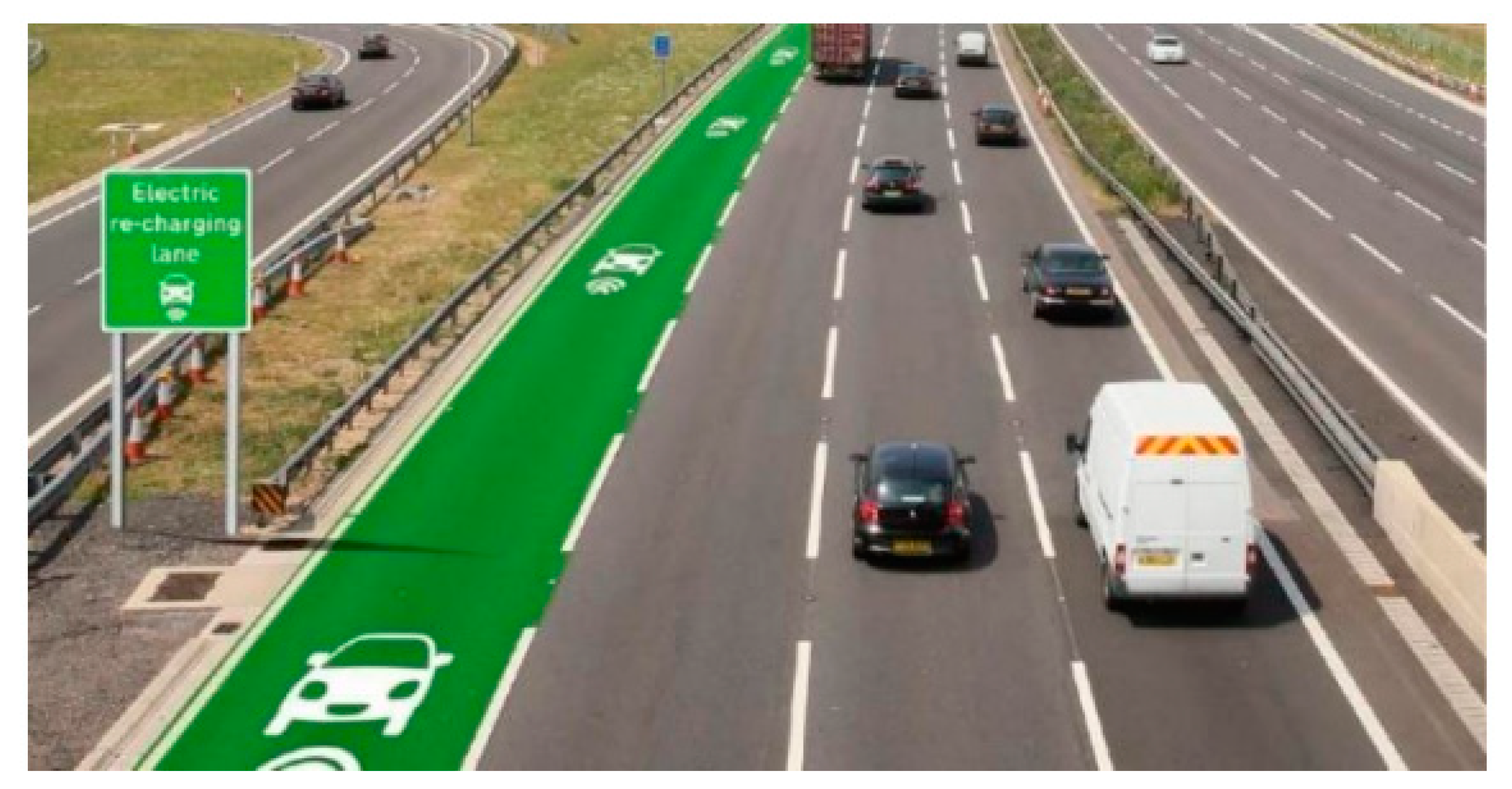
Through the DWCS, electric vehicles can use highways without fear of remaining uncharged, as it has the potential to recharge them in motion. Due to the high cost of DWCSs, researchers have thought of determining the minimum infrastructure cost for electric vehicles; in general, they used two methods to obtain it. In the first method, they took the origin road as the reference; then, each power transmitter’s start point and endpoint were described by the travel distance from the reference point; JANG et al. used this method to develop the DWCS infrastructure for electric buses [2]. The second method was used by Bourzik and EL Hilali Aaloui [3]. The principle is to divide the road into potential segments with the same length and determine by vehicle load constraints which segments will be occupied by a DWCS. The two methods mentioned include building a DWCS infrastructure for electric vehicles (Figure 2).
To build a highway road with a DWCS for electric vehicles with heterogeneous batteries (Figure 2) at the least cost, this study considers the work of Bourzik and EL Hilali Aaloui [3] and consists of dividing the road into two zones (Figure 3), the main road without the DWCS and the second road with the DWCS.
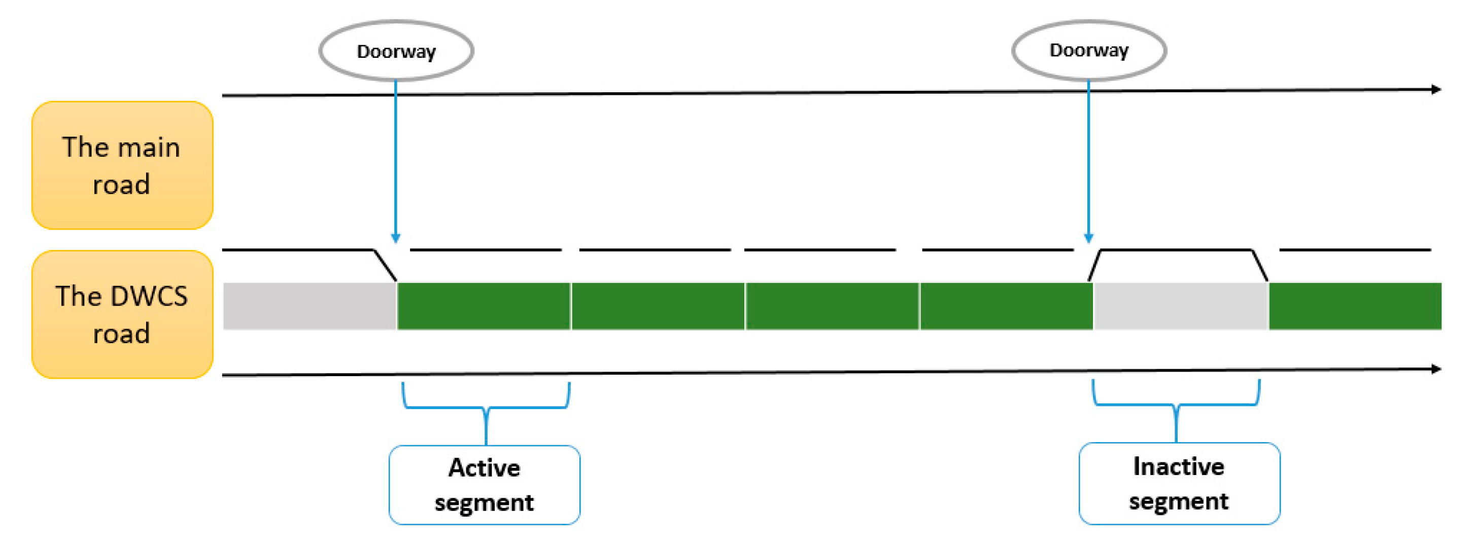
Bourzik and EL Hilali Aaloui subdivided the second road into congruent segments; they considered each segment as a potential transmitter and defined two types of segments. The active segment is the part of the road equipped with the DWCS; the vehicles can use this segment type to charge their batteries. The inactive segment is the part of the road without DWCS; this type of segment is not used. They determined the location of the active and the inactive segments according to the vehicle’s load; if at least one vehicle needs to charge its battery, the segment will be active, or inactive if not. The highway road with a DWCS proposed in [3] is shown in Figure 4. If a vehicle needs to charge, it can enter the DWCS road by the doorway at the beginning of the active segment and not leave this road until the next doorway at the end of the active segment.
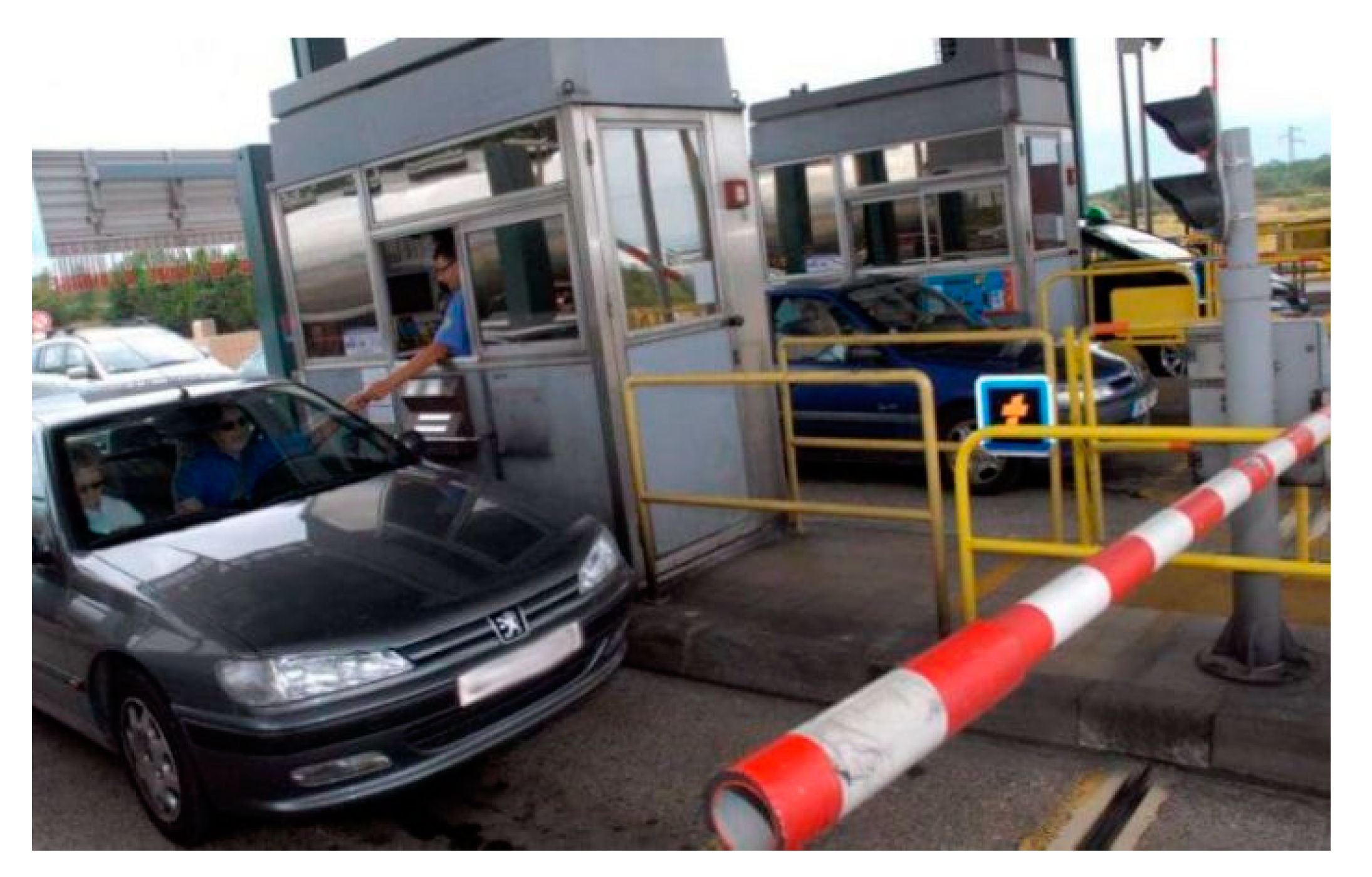
On the other hand, the usage of a DWCS road would not be free; each vehicle type must pay the service cost, which depends on the vehicle type and the usage duration. This factor was not considered in [3], because they focused on minimizing the infrastructure cost. For this purpose, this work focuses on installing a set of gates on the road to organize the payment and the usage of the DWCS by the vehicles. The usage cost of the DWCS depends on the vehicle type and the usage duration; for this, the road has to contain special gates, which can determine the usage duration of each vehicle type. This paper assumes that the entry gate would provide a ticket for each vehicle that needs to use the DWCS road to localize it, and the exit gate would have the potential to calculate the usage duration from the ticket provided at the entry gate and have a payment system to retrieve the usage cost from the vehicles. Figure 5 shows an example of the entry and exit gates.
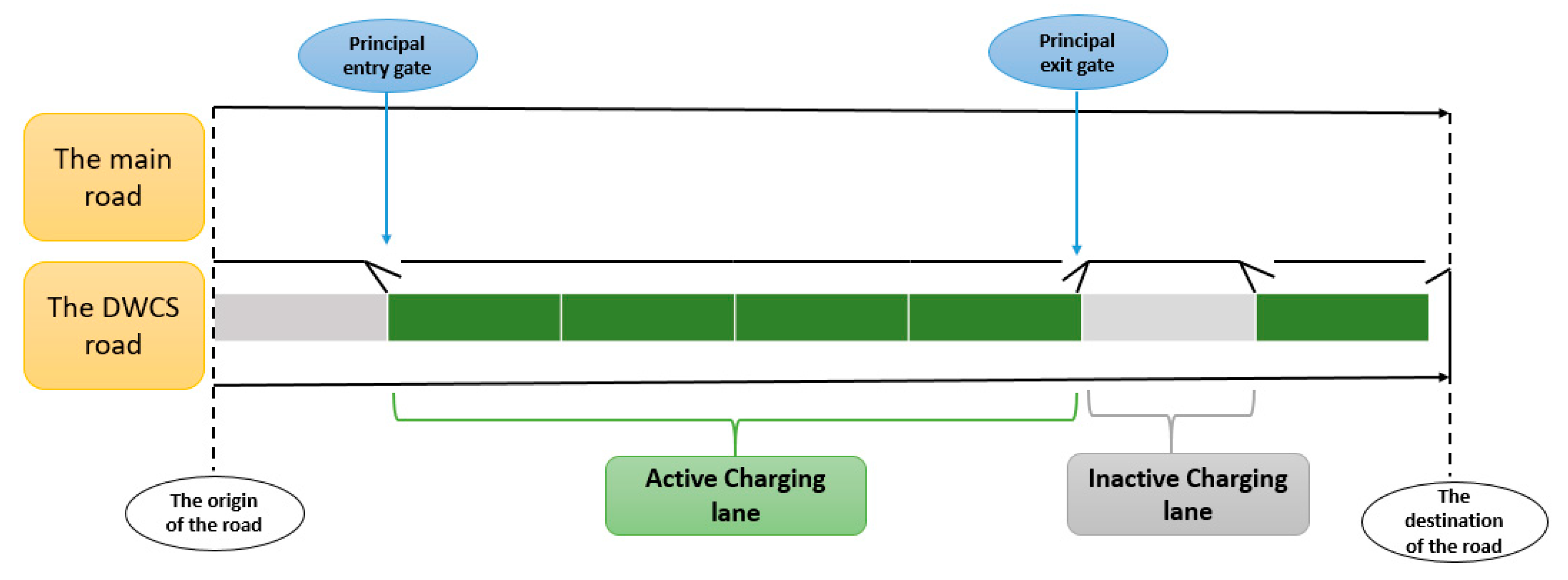
To determine the location of the entry and exit gates on the road, the successive active (inactive) segments were assumed to form an active (inactive) charging lane. Each active lane would have a principal entry gate to the DWCS at the beginning and an exit gate at the end of the main road (Figure 6). Between each main entry and exit gate, the goal would be to install a set of gates to ensure a suitable trip for each vehicle type without remaining out of charge based on the minimum total usage cost (T.U.C), which is the first objective of this work.
Due to the heterogeneity of vehicles, the use of the DWCS would differ from one vehicle to another; therefore, each vehicle type needs a set of gates to minimize its T.U.C, which would increase the number of gates; for this purpose, the second objective is to minimize the total number of gates on the road.
The main objective of this paper is to find the optimal location for a power transmitter’s gates on a highway to ensure the trip of a fleet of heterogeneous vehicles with the minimum T.U.C for each type. The first section presents some previous work related to the topic. The next part transforms the problem into a mathematical model with constraints and presents the different notations, data, constraints, and objective functions of the proposed model. The third section proposes solving the problem with the CPLEX optimizer for limited instances to validate the mathematical model. The next part presents the resolution of the problem using the NSGA-II metaheuristic. Finally, the results are analysed and discussed in order to demonstrate the efficiency of the proposed model and methods used.

2. Literature Review

The electric vehicle (EV) is the future mode of transport globally because it is economical and safe for the environment. Inductive charging has the advantage of charging EVs without contact; for this reason, inductive charging and electric vehicles are widely studied by researchers.
Induction charging is composed of three types of charging systems. The first is stationary wireless charging (SWC), which can supply an EV by induction in the stop mode. Many companies around the world have developed their SWC systems, such as the Waseda Electric Bus in Japan, with a power ranging from 30 kW to 150 KW for a distance between transmitter and receiver coils of 105 mm. The vehicle is recharged at each bus stop [4]. Alwesabi et al. [5] developed a mixed-integer mathematical model to simultaneously select the optimal location of DWC facilities and find the optimal battery sizes of electric buses (EBs) for the system based on data obtained from the transportation centre at Binghamton University.
The second type of charging is quasi-dynamic wireless charging (QWC), with which an EV can be charged when it is moving slowly or in the stop-and-go mode. The last type is called dynamic wireless charging (DWC), where the vehicle is charged while running in this charging mode. The DWC is conducted by a specially equipped track where coils are placed that only activate when the vehicle passes over them, resulting in electric roads. This solution can reduce the required capacity and thus the weight and price of vehicle batteries. In 2010, the Korea Institute of Science and Technology (KAIST) designed a contactless bus with an 85% efficiency for a power of 100 kW operating at a frequency of 20 kHz [2].
For the former category, researchers at the Korea Advanced Institute of Science and Technology (KAIST), such as Young [2], sought to ensure the displacement of electric buses with homogeneous batteries during their services using the dynamic wireless charging system. They produced a mathematical model to find a compromise between the infrastructure and battery costs. JEONG et al. [6] modelled the same problem, but added the impact of the battery’s degradation. In their work, the battery life of the bus was calculated by its service number in the DWCS lifetime.
Owing to the uncertainty of power consumption and electric bus travel time, Liu et al. [7] developed a robust mathematical model to optimize the system’s recharging deployment plan. They used Utah State University as a case study. Liu and Song [8] extended the charging lane deployment model proposed by Chen et al. [9] for plug-in hybrid electric truck operations. Chen et al. [10] developed analytical models to optimize the deployment of dynamic charging facilities on a transit system to serve the daily operation of electric buses.
Fuller [11] presented a flow-based overall coverage model to minimize the capital cost of deploying dynamic recharging infrastructure for the California highway system to meet the recharging needs of electric vehicles travelling between significant sources and destinations in the state. At the same time, drivers may be motivated to slow down their electric vehicles in the charging lanes to regain more power.
Mouhrim et al. [12] considered several paths between the arrival station and the base station of electric buses. They sought a compromise between the infrastructure cost of the induction charge and the cost of the batteries. In this work, the battery cost was proportional to the battery capacity. Elbaz et al. [13] considered a multi-path network between the base station and the arrival station to model the problem of determining the minimum infrastructure cost of electric buses with homogeneous batteries. They added the back-and-forth impact to Mouhrim’s work. Xiaotong Sun et al. [14] investigated the optimal deployment of static and dynamic charging infrastructure considering the interdependency between transportation and power networks.
Yung et al. [15] proposed a mathematical study to find the minimum number of power transmitters on the road that could ensure the trips of a set of homogenous electric trams based on the minimum battery capacity.
Bourzik and EL Hilali Alaoui [3] presented the optimal location of the wireless charging infrastructure for EVs with heterogeneous batteries; they conducted their study on a highway. To build the infrastructure, they considered a road subdivided into segments with the same length to determine which segment would be occupied by the DWCS.
Most of the research cited focused on allocating dynamic wireless charging infrastructure. Although these researchers developed the infrastructure for electric vehicles, they considered the cost of the infrastructure, which they sought to optimize. This study considers a case where the electric vehicle’s infrastructure is predefined, and seeks to organize the use and the payment for the use of the DWCS by the vehicles. Due to the heterogeneity of the batteries, it was assumed that the infrastructure was built by Bourzik and EL Hilali Alaoui’s method [3] because they took into account the heterogeneity of the vehicles’ batteries in their work. To organize the use and the payment of the DWCS by the vehicles, the goal is to create the minimum number of entry and exit gates to the DWCS road and to minimize the usage cost of each vehicle type during their trip. This work conducts this study on a highway because electric vehicles’ batteries drain very quickly due to the high speed and the long distance between the origin and the destination, which increases the usage cost.

3. Problem and Modelling

3.1. Problem Description and Objective

This work considers a highway road with a DWCS. The induction charging transmitter system was constructed by Bourzik and EL Hilali Aloui’s method [3]. As noted previously, the location of the active and inactive segments was predefined, and the segments with the same status formed a series of segments. The active series (active lane) had an entry gate at the beginning and an exit gate at the end, and the inactive series were inaccessible. The active series of segments were placed next to the main road as charging lanes (Figure 5).
The fleet of heterogeneous battery vehicles was placed at the origin of the highway, noted by O, to begin the trip to the destination noted by S. The vehicles would use the charging lanes of the highway to not remain out of charge. As access to charging lanes would not be free, this study seeks to minimize the T.U.C of DWCS for each vehicle. To achieve this goal, the aim was to create new entry and exit gates for each charging lane. Owing to the heterogeneity of vehicle batteries, the usage of the charging lanes’ gates differs from one vehicle to another, which would increase the number of gates on the road; for this reason, the goal was to minimize the number of gates on the highway, automatically minimizing the infrastructure cost.

3.2. Problem Formulation, Data, and Decision Variables

In this subsection, the objective is to transform the problem into a mathematical model with constraints. Let O be the origin of the highway and S be the destination. The set of vehicles is denoted by φ , and each type is indexed by α ϵ φ. Moreover, a vehicle of each type begins the trip from O to S .
As mentioned previously, the successive segments with the same status (active or inactive) formed a charging lane (series of segments). The first series of segments is denoted by 1, the last series is denoted by N , and the other lanes are denoted by g = 1 N . The location of the active lanes (segments series with the DWCS) is predefined; let U g be a binary variable defined by:
U g = { 1     i f   t h e   l a n e   g   i s   a c t i v e 0                       o t h e r w i s e    
Let N A be the set of active lanes, with N A = { g / U g = 1 } .
To create new entry and exit gates, the access road of each active lane is discretized into potential gates (PG) indexed by i = 1 , ,   N g , with 1 as the index of the principal entry gate and N g as the principal exit gate ( N g being the number of potential gates on lane g ) (Figure 7). Each inactive lane is inaccessible; for this reason, it will not have any gates. In addition, each active lane has a principal entry gate at the beginning, noted by 1 , and a principal exit gate at the end, noted by N g ; both gates must be open.
Each gate is associated with a decision variable P i g , with i = 1 , ,   N g defined by:
P i g = { 1       i f   t h e   i   t h   g a t e   o f   t h e   l a n e   g   i s   o p e n 0   o t h e r w i s e                                                        
In the model, each gate can be used to enter or exit the charging lane, and ρ is the necessary distance between two consecutive open gates. Distance ρ is the required number of closed gates between two consecutive open gates. Let C be the installation cost of one gate on the road.
As each vehicle type has its own characteristics, E l o w α and E u p α are the minimum charge and the maximum charge of vehicle α . Let T α   ( t ) and D α ( t ) be the charging rate and the discharging rate of vehicle α , respectively. U U C α   is the unit usage cost of the DWCS of vehicle α .
To determine the open gates in each charging lane, each type of vehicle makes one trip from O to S. The vehicles will pass through each lane’s potential gates; let t g , i α be the arrival time of vehicle α at the i t h gate of lane   g . Let t O α be the arrival time of vehicle α at the origin O of the highway. The vehicles may slow down on the DWCS road to charge more energy; and δ g , ( i j ) α is the maximum allowable travel time between two consecutive gates, i and j , when vehicle α uses the DWCS of lane g .
Let I α ( t )   be the amount of energy in the battery α at time   t ; this quantity is described as:
d I α ( t )   d t = {     T α   ( t )         i f   t h e   v e h i c l e   α   i s   i n   c h a r g i n g   m o d e   o n   t h e   D W C S       D α   ( t )                       i f   t h e   v e h i c l e   α   i s   i n   t h e   m a i n   r o a d                                            
During the trip, the vehicles decide to use the gates to enter or leave the charging lanes; therefore, to determine the gates used for each vehicle type, the decision variable   y g , i α is defined as follows:
y g , i α = { 1     i f   the   vehicle   type   α   u s e   t h e   i   t h g a t e   o f   t h e   c h a r g i n g   l a n e   g 0   o t h e r w i s e  
To determine the charging cost of each vehicle type, the decision variable   w g , ( i , i + 1 ) α is defined as follows:
w g , ( i , i + 1 ) α = { 1     i f   t h e   vehicle   type   α   u s e s   t h e   c h a r g i n g   l a n e   g   b e t w e e n   t h e   g a t e s   i   a n d   i + 1 0   o t h e r w i s e              
Variables w g , ( i , i + 1 ) α and y g , i α depend on the vehicle type, because the usage of the charging lanes differs from one type to another due to the heterogeneity of the batteries.

3.3. Constraints

The mathematical model constraints are constructed in this section. As mentioned previously, each vehicle type makes one trip from O to S, and each battery type has a full charge at the origin of the road:
I α ( t O α ) = E u p α                         α ϵ φ
To ensure the trip of each vehicle type without remaining out of charge in the active charging lanes, the following constraints must be verified:
I α ( t g , i α ) + t g , i α t g , i + 1 α ( D α ( t ) × ( w g , ( i , i + 1 ) α 1 ) + T α ( t ) × w g , ( i , i + 1 ) α ) d t E l o w α
α ϵ φ ,   g ϵ N A ;       i = 1 , , N g 1
The first term of the constraint presents the battery charge of vehicle α at its arrival time at the i th gate of lane g . The second term presents the load consumption of vehicle α during its travel between gates i and i + 1 of lane g ; the vehicle loses this energy if it has not used the charging lane g between gates i and i + 1   ( w g , ( i , i + 1 )   α = 0 ) . If the vehicle uses the charging lane between gates i and i + 1   ( w   g , ( i , i + 1 ) α = 1 ) , the second term will be cancelled because the battery is in the recharge mode, and the third term represents the amount of energy recharged. Then, constraint (6) presents the battery level of the vehicle α at its arrival time at gate i + 1 of the charging lane g , which must always be greater than the battery’s minimum load. In other words, each type of vehicle uses the recharge track so that the energy level is greater than the minimum load of the vehicle.
To ensure the trip of each vehicle type without remaining out of charge in the inactive charging lanes, the following constraints must be verified:
I α ( t g , N g α ) + t g , N g α t g + 1 , 1 α ( D α ( t ) d t E l o w α )               α ϵ φ ,                 g ϵ N A
The first term of (7) presents the amount of energy of vehicle α at the last gate of the active charging lane g , and the second term is the energy consumption due to the travel between the last gate of active charging lane g and the first gate of charging lane g + 1 . Then, constraint (7) presents the variation in the battery charge during the trip in an inactive charging lane, which must be greater than the minimum load of the vehicle.
The vehicle batteries are operated in such a way that the level of charge does not exceed its maximum charge; for this, the following constraints must be verified:
I α ( t g , i + 1 α ) = min ( E u p α ,   I α ( t g , i α ) + t g , i α t g , i + 1 α ( D α ( t ) × ( w g , ( i , i + 1 ) α 1 ) + T α ( t ) × w g , ( i , i + 1 ) α ) d t )
α ϵ φ ,     g = 1 , , N ;             i = 1 , , N g 1
Constraint (8) updates the remaining charge at each ( i + 1 ) t h gate. The battery energy level of each vehicle α should be lower than the upper limit of the battery E u p α . If the energy amount is higher than the upper limit, then the energy level would be E u p α .
Constraint (9) updates the remaining charge of vehicles at the first gate of each active charging lane:
I α ( t g + 1 , 1 α ) = I α ( t g , N g α ) + t g , N g α t g + 1 , 1 α ( D α ( t ) d t )     α ϵ φ ,     g ϵ N A    
The usage of the segment gates differs from one type to another due to the heterogeneity of batteries. The following constraints determine the usage of gates for each vehicle:
      y g , i α = ( 1 w g , ( i 1 , i ) α ) × w g , ( i , i + 1 ) α + ( 1 w g , ( i , i + 1 ) α ) × w g , ( i 1 , i ) α    
α ϵ φ ,           g ϵ N A ,   i = 2 , , N g 1                      
y g , 1 α = w g , ( 12 ) α                                                                     α ϵ φ ,                       g = 1 , , N  
y g , N g α = w g , ( N g 1 , N g ) α                                         α ϵ φ ,                       g = 1 , , N  
For constraint   ( 10 ) :
  • If w g , ( i 1 , i ) α = 0 , the vehicle α has not used lane g between gates i 1 and i ; this means that vehicle α is on the main road, so if w g , ( i , i + 1 ) α = 1 , the vehicle decides to use lane g between gates i   and i + 1 ; in this case, it enters the lane by the i t h gate, found with the constraint y g , i α = 1 ;
  • If w g , ( i 1 , i ) α = 1 , vehicle α uses lane g between gates i 1 and i , so if w g , ( i , i + 1 ) α = 0 , the vehicle does not need to use lane g between gates i and i + 1 and decides to leave the lane by the i t h gate, found with the constraint y g , i α = 1 ;
  • If w g , ( i 1 , i ) α = w g , ( i , i + 1 ) α = 0 , vehicle α is on the main road between gates i 1 and i and it stays on the main road between gates i and i + 1 , so vehicle α does not use gate i and involves y g , i α = 0 . The same case ( y g , i α = 0 ) if w g , ( i 1 , i ) α = w g , ( i , i + 1 ) α = 1 .
Constraints (11) and (12) replace constraints (10) at the first and the last gates of each active charging lane.
To determine the open gates of each lane, constraints (13) and (14) are used:
y g , i α P i g                 α ϵ φ ,     g   ϵ   N A ,     i = 1 , , N g            
P i g α = 0 | φ | y g , i α                           g   ϵ   N A       ,         i = 1 , , N g              
If there is at least one α   ϵ   φ , such that   y g , i α = 1 , there is at least one vehicle type that uses the i t h gate of lane g ; this implies that gate i must be open, according to constraint (13) ( 1 P i g ) .
In the same context, if y g , i α = 0 for all α   ϵ   φ , no one vehicle type uses the i t h gate of lane g ; this implies that gate i must be closed, found with constraint (14) ( P i g 0 ) . Then, constraints (13) and (14) ensure that the i t h gate of lane g is opened if, and only if, at least one type of vehicle α uses it.
In order to avoid the opening of two successive potential gates on the same charging lane, a necessary number of gates to be closed between two successive gates is chosen, and the open gates must satisfy the following constraint:
i = k ρ + k P i g 1             g   ϵ   N A ;         k = 1 , , N g ρ        
Vehicles can slow down to gain additional charging time; constraint (16) ensures that the travel time between two successive gates of each vehicle type on the active lane is no greater than the maximum allowable travel time δ g , ( i , j ) α :
( t g , i + 1 α t g , i α )   w g , ( i , i + 1 ) α δ g , ( i , i + 1 ) α           α ϵ φ ,     g = 1 , , N ,     i = 1 , , N g 1
In this case, the recharge duration is limited to a maximum duration to avoid the issue of overload, which results in an additional recharge cost; i.e., each vehicle has a maximum recharging time in the recharging lane.

3.4. Objective Function

The first objective in this paper is to minimize the total usage cost of charging lanes for each vehicle type, which is represented by:
  min α ϵ φ U U C α × g = 1 N i = 1 N g 1 w g , ( i , i + 1 ) α × ( t g , i + 1 α t g , i α )    
where U U C α is the unit usage cost of vehicle α for using an active charging lane. t g , i + 1 α t g , i α represents the charging time of vehicle α while using the g t h   charging lane between gates i and i + 1 if w g , ( i , i + 1 ) α = 1 . If not ( w g , ( i , i + 1 ) α = 0 ) , the vehicle has not used the charging lane g between gates i and i + 1 ; in this case, the objective function (17) will be zero for rank i .
The second objective is to minimize the total number of open gates in each active charging lane, which is obtained by the following function:
  min C × g = 1 N i = 1 N g P i g          
where C is the unit cost of opening a new gate; then, function (18) represents the total cost of the open gates on the road.

4. Problem Solving

In this work, the aim is to minimize the usage cost of the charging lanes for a fleet of heterogeneous vehicles during their trip on the highway. For this purpose, the goal is to create new entry and exit gates for each charging lane of the highway at the lowest cost. In this section, the problem is solved using the CPLEX optimizer for limited instances to validate the proposed mathematical model. The resolution approach to the problem using the NSGA-II metaheuristic is presented.

4.1. Problem Validation

CPLEX optimizer [16] provides flexible, high-performance mathematical programming solvers for linear programming, mixed integer programming, constraint programming, and quadratic constraint programming problems. These solvers include a distributed parallel algorithm for mixed-integer programming to take advantage of multiple computers to solve complex problems. Validating the model with data and constraints makes it possible to verify the operation of the constraints. Once a solution is found, the formulation checks whose constraints have been modelled so they can be alerted in case of error. To validate the mathematical model by CPLEX, some constraints are modified as follows:
Constraint (8) is replaced by the following constraints:
I α ( t g , i α ) + t g , i α t g , i + 1 α ( D α ( t ) × ( w g , ( i , i + 1 ) α 1 ) + T α ( t ) × w g , ( i , i + 1 ) α ) d t   E u p α     I α ( t g , i + 1 α ) = E u p α
I α ( t g , i α ) + t g , i α t g , i + 1 α ( D α ( t ) × ( w g , ( i , i + 1 ) α 1 ) + T α ( t ) × w g , ( i , i + 1 ) α ) d t < E u p α    
  I α ( t g , i + 1 α ) = I α ( t g , i α ) + t g , i α t g , i + 1 α ( D α ( t ) × ( w g , ( i , i + 1 ) α 1 ) + T α ( t ) × w g , ( i , i + 1 ) α ) d t                          
To complete the linearization process, constraint (12) is replaced with the equivalent following constraints:
w g , ( i 1 , i ) α w g , ( i , i + 1 ) α       y g , i α = 1              
w g , ( i 1 , i ) α = w g , ( i , i + 1 ) α       y g , i α = 0    
The other constraints remain the same.

4.1.1. Transport Network Data

To solve the problem by the CPLEX optimizer, the road between the origin O and destination S is 7500 m, and four types of vehicles need to travel from O to S without remaining out of charge by the minimum infrastructure cost. The segment of length 100 m is a reference unit and the necessary data relative to each segmentation used during the resolution are deducted. Table 1 and Table 2 contain the energy supply rate, the energy consumption rate of each vehicle type, and the other data.
The validation of the proposed mathematical model with the CPLEX optimizer was based on the same example used by Bourzik and EL Hilali Aaloui [3]. They considered a road between the origin O and destination S to be 7500 m, and four vehicle types that needed to travel from O to S.
To ensure the trip of the four vehicles without remaining out of charge by the minimum infrastructure cost, they discretized the road into a segment length of 200 m and determined the active and inactive segments according to vehicle load constraints. The results found in [3] were used to produce the active and the inactive charging lanes of the example. Table 1 and Table 2 contain the energy supply rate, the energy consumption rate of each vehicle type, the unit cost for using the charging lanes, the lane’s status, and other data.
Each active charging lane has principal entry and exit gates, and the access road of each active lane is discretized into potential gates. As the example has four vehicle types, four potential gates in each active charging lane are used to allow each vehicle type to exit the charging lane before the principal exit gate if it minimizes its T.U.C. Let C = 1000 be the unit cost of opening a new gate.

4.1.2. Results

The problem is solved for each of the objectives, because CPLEX can only solve mono-objective problems. The first objective is to minimize the total usage cost (T.U.C) of each vehicle type, and the second objective is to minimize the number of open gates on the road.
The blue column in Table 3 presents the total cost of open gates on the road, and the T.U.C of each vehicle type of the solution found with the objective of minimizing the T.U.C for vehicles. In this case, the total cost of open gates is equal to 19,000, and the T.U.Cs for vehicles 1, 2, 3, and 4 equal 137.5, 127.5, 150, and 126, respectively. The green column provides the results, with the main objective being minimizing the number of open gates on the road. In this solution, the total cost of an open gate on the road is equal to zero, and the T.U.Cs for vehicles 1, 2, 3, and 4 equal 137.5, 127.5, 150, and 126, respectively.
To ensure the trip of each vehicle type without remaining out of charge and based on the minimum usage cost, the gate cost is 19,000, which is the cost to create 19 gates on the road. On the other hand, each vehicle type uses the gates depending on the battery state. Due to the heterogeneity of batteries, each vehicle type uses a set of gates to minimize its T.U.C; for this reason, the number of gates on the road increases.
In the case of minimizing the set of gates on the road, the number of gates found was 0 on the road because the main entry and the exit gates of each charging lane can ensure the trip of the vehicles without remaining out of charge. The T.U.C of each vehicle type increases in this case because the vehicles will have to use the full active charging lanes.

4.2. Approach to Solving the Problem

In the previous section, the problem was solved for limited instances and for each one of the objectives using the CPLEX optimizer. In this section, the non-dominated sorting genetic algorithm NSGA-II is adopted to solve the problem, and the main steps of the method and its application to the problem are described.

4.2.1. NSGA-II

NSGA-II is a modified version of the NSGA algorithm [17]. The crossover, recombination, and mutation operators (see [18] and [19] for more details) allow the creation of a daughter population Q0 with the same size as the parent population P0. Moreover, the ranking of equally dominant individuals is based on a dispersion measure called crowding distance [20]. Algorithm 1 represents the main steps of NSGA-II (more details in [21]).
Algorithm 1: NSGA-II
  1.   t   0
  2. While t <   M   do
  3. R t   P t     Q t
  4. F     fast - non - dominated - sort   ( R t )
  5. P t + 1
  6.   i   0
  7.   While   | P t + 1 | + | F i |   N   do
  8.   P t + 1   P t + 1   F i
  9. Apply crowding-distance-assignment F i
  10.   i   i + 1
  11.   end   while
  12.   sort   ( F i , < n )
  13.   P t + 1 P t + 1 F i [ 1 : ( N | P t + 1 | ) ]
  14.   Q t + 1   create   new   population   ( P t + 1 )
  15. t t + 1
  16. end while
The population Pt necessarily converges to a set of points on the Pareto front, as non-dominated solutions are preserved across generations. Furthermore, the dispersion criterion (crowding distance) guarantees good population diversity [22].

4.2.2. Crowding Distance (CD)

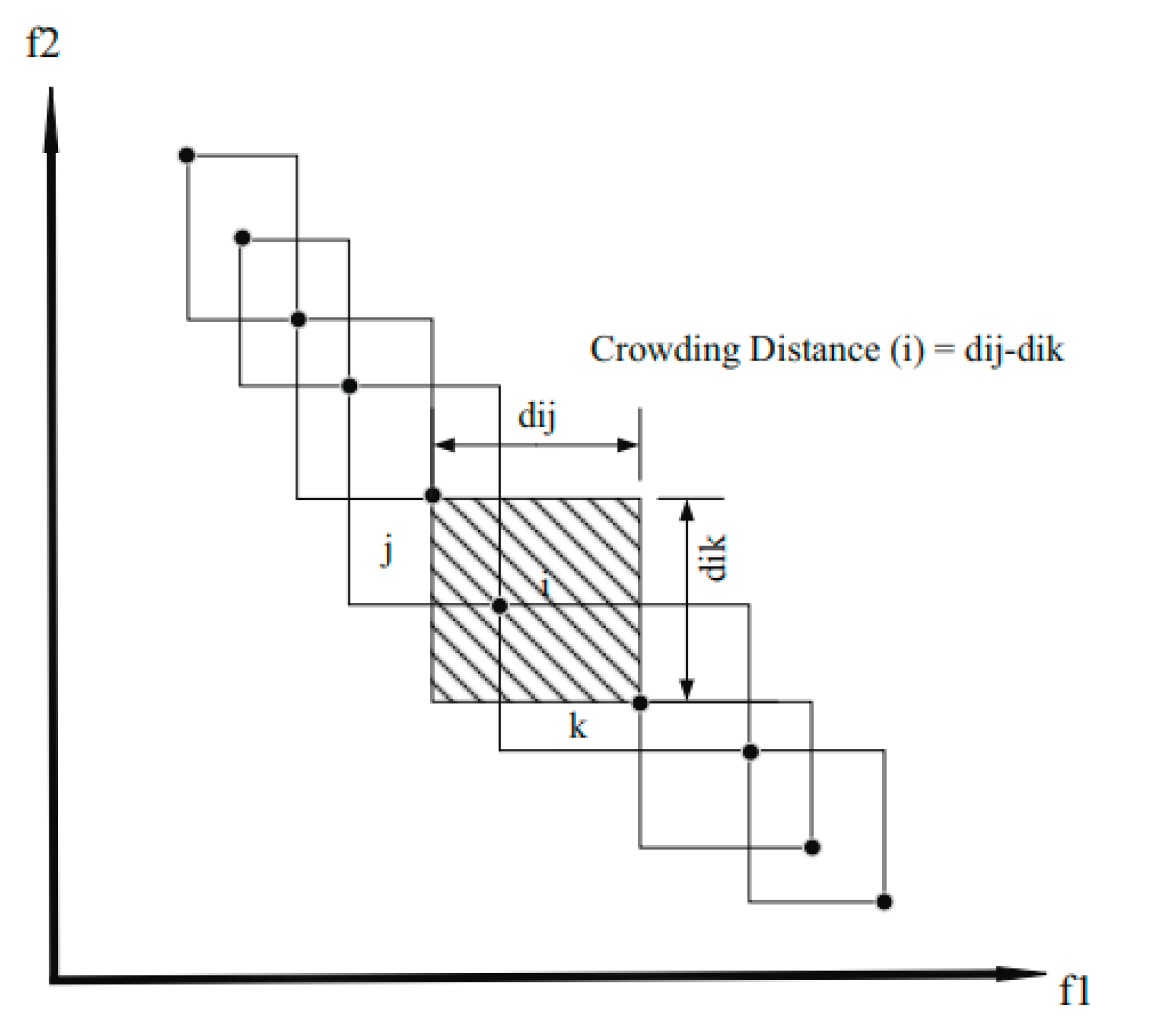
The crowding distance operator [23] guides the selection process to a uniformly expanding Pareto optimal front at various stages of the algorithm. This subroutine was used to compare other members of the United Front. In other words, the CD was for sorting a specific front end. According to Formula (21), calculate the number of CDs of each member compared with the next and previous members and the first and last members (illustrated in Figure 8) [24].
d i j = | f 1 i f 1 j | f 1 m a x f 1 m i n ,   d i k = | f 2 i f 2 k | f 2 m a x f 2 m i n ,   C D i = d i j + d i k
It is worth noting that, to obtain the best answer, the answer needs to be placed and distributed regularly on the Pareto front. The higher the magnitude of CD, the more regular the order of responses in the Pareto front. Therefore, a higher CD amount means a priority standard for each member compared with others on the same front. When calculating the CD of the first and last members [25], it is worth noting that the CD of the previous member to the first member is assumed to be ∞, and the CD of the next member is assumed to be +∞. Therefore, the CD of these points is ∞: this means that, between two chromosomes with different non-dominant ranks, the lower-rank answer is selected. Otherwise, if both answers belong to the same frontier, the answer in the region with the lower number of answers is selected.

4.3. Application of the NSGA-II

This section presents the application of the NSGA-II algorithm to the problem. For this, different steps of NSGA-II are defined in this case:

4.3.1. Encoding Strategy

To adopt the approximated methods, this work considers that a solution to the problem is described as follows:
  • Open gates in each charging lane of the road are coded in the form of a chromosome with a matrix   ( N × N i ) , noted A = ( a i j ) i = 1 N j = 1   N i with:
    a i j = { 1                 i f   t h e   j   t h     g a t e   o f   t h e   l a n e   i   i s   o p e n                             0                                                                                                 o t h e r w i s e                                                      
    where N is the number of charging lanes on the road and N g is the number of gates on charging lane i . The number of columns of A depends on   N g , which differs from one charging lane to another; so, to generate A , let N N i be the number of columns of the matrix A , with N N i = max 1 i 1 N g , so A = ( a i j ) i = 1 N j = 1   N N i and a i j = 0     N i < N N i .
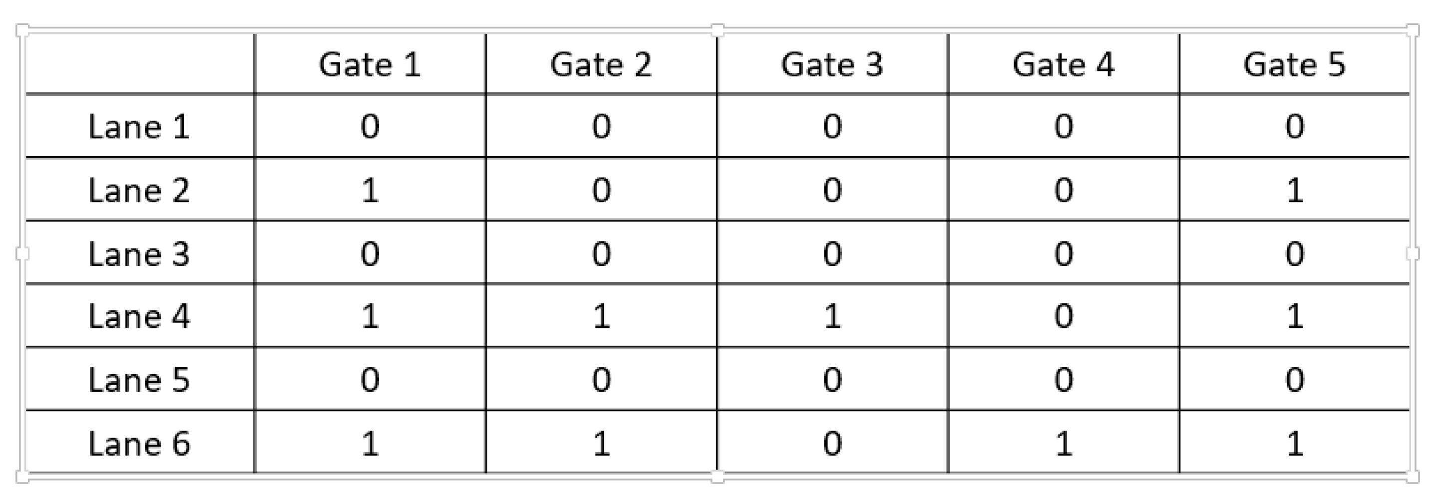
As mentioned previously, each active charging lane has principal entry and exit gates, which must open; for this, a i 1 = U i and a i N i = U i   i = 1 N . Figure 9 shows an example of the open gate matrix with six charging lanes and five potential gates, U 2 = 1 ,   U 4 = 1 , and   U 6 = 1 .
  • The used gates of each vehicle type is a table noted by B =   ( b k i j ) j = 1   N i k = 1 | φ | i = 1   N , with:
    b k i j = { 1   i f   t h e     v e h i c l e   k   u s e   t h e   j t h   g a t e   o f   t h e   l a n e   i 0                                                                 o t h e r w i s e  
This part of the solution is feasible if each type of vehicle leaves the DWCS road after using the active charging lane. As the vehicles begin the trip from the main road, the first use of each potential gate means that the vehicle enters the DWCS road, and the second use of the following potential gate means that the vehicle uses the gate to exit the DWCS road. For this, this part of the solution is feasible if, and only if, j = 1 N i b k i j is an even number for all k   ϵ   φ and i = 1 , ,   N .

4.3.2. Initial Population

Before generating a population, it is necessary to generate an individual. In this case, a vehicle type is randomly selected and ensures its trip on the road while respecting the model’s constraints. For the second iteration, another vehicle type is randomly selected and verified if the last type’s open gates ensure the selected vehicle’s trip without remaining out of charge; if not, the procedure opens another gate for the vehicle until the model constraints are met. The procedure stops when all of the vehicles can complete the trip without remaining out of charge.
The procedure consists of testing at each iteration whether the gates used by the last vehicles can ensure the travel of the selected vehicle without remaining out of load in order to minimize the number of open gates for each individual using Algorithm 2.
Let:
  • S be the set of selected vehicles;
  • φ be the set of vehicles indexed by α ;
  • X be the set of open gates;
  • P be the set of the potential gates indexed by i and p ;
  • G be the set of the charging lane indexed by g .
Algorithm 2: Generation of an individual
  17.   S = ,   X =
  18. for each vehicle α
  19.   While   S = do:
  20. Choose   randomly   a   vehicle   α   ϵ   φ   and   α   S
  21. If the X ensures the trip of the α without remaining out of charge
  22. S = S   { α }
  23. Else
  24. for each charging lane g
  25. for each potential gate i
  26. If   I α ( t g , i α ) < I l o w α and g is active
  27. Make the gate i   open   and   X = X {   i   }
  28. end if
  29. else if g is inactive
  30. do :   p = 1
  31. If   the   gate   p   of   the   lane   g 1 is closed
  32. Make p   open   and   X = X {   p   }   and   p = p + 1
  33. end if
  34. while   ( I α ( t g , i α ) < I l o w α )
  35. end if
  36. else Make i closed
  37. end for
  38. end for
  39. end while
  40. end for

4.3.3. Crossover Procedure

The open gates in each charging lane and the usage gates of each vehicle type represent the individual in the problem; for this purpose, the crossover used in this work is conducted in two parts. The first part is a crossing for two matrices of the open gates of charging lanes A 1 and A 2 of two individuals’ parents P 1 and P 2 . The second part is a crossing of two tables of the usage gates of vehicles T1 and T2; the proposed crossing procedure is described below:
-
For the first part of the crossover:
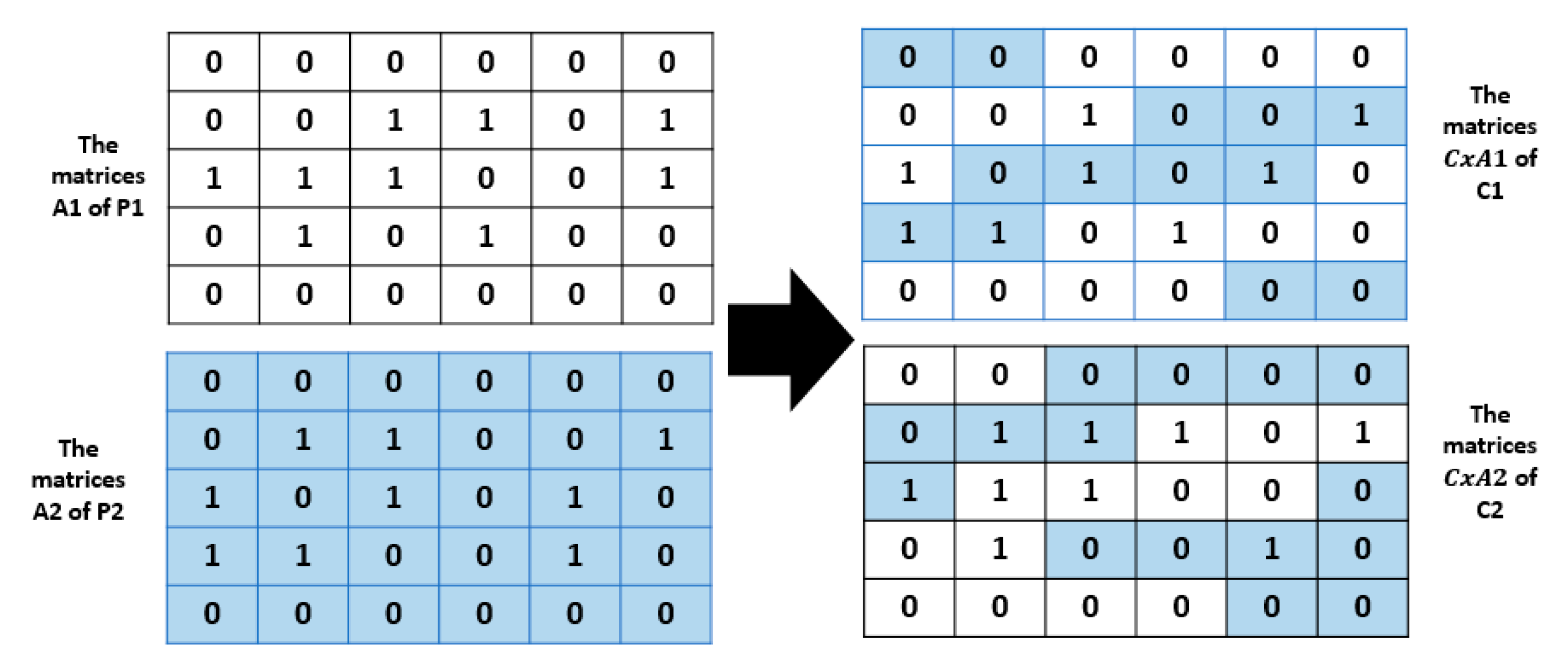
A crossing point h is randomly chosen for each charging lane in the interval [ 0 , N i ] , and then exchange the first h boxes of the gates between the two parents to generate the matrices C x A 1 and C x A 2 of two children, C1 and C2, respectively (see Figure 10).
The table C x B 1 (resp. C x B 2 ) of the usage gates of the vehicles of each child C1 (resp. C2) is generated so that each vehicle type uses the necessary open gates in the matrices C x A 1 (resp. C x A 2 ) to not remain out of charge. The part colored in blue in   C x A 1 generated from A2 of P2 and the part colored in white generated from A1 of P1, and the same for C x A 2 .
To verify the feasibility of these new individuals, C1 and C2, the heuristic illustrated in the following algorithm is used:
-
For the second part of the crossover:
For each vehicle type α , a crossing point k is randomly chosen for each charging lane in the interval [ 0 , N i ] , and then the first h boxes of the matrices B are exchanged between the two parents to generate the matrices C x B 1 and C x B 2 of children C1 and C2, respectively.
Table C x A 1 (resp. C x A 2 ) of the open gates in each charging lane of child C1 (resp. C2) is generated so that each potential gate is open if it is used by at least one vehicle.
To verify the feasibility of these new individuals, C1 and C2, the heuristic illustrated in algorithm 3 is used.
Algorithm 3: Correction Algorithm
  1. for each vehicle α
  2. for each charging line g
  3. for each potential gate i
  4. If I α ( t g , i α ) < I l o w α and g is active
  5. Make the gate i open
  6. end if
  7. else
  8. if g is inactive
  9. do :   p = 1
  10. If   the   gate   p   of   the   lane   g 1 is closed
  11. Make p   open   and   p = p + 1
  12. end if
  13. while   ( I α ( t g , i α ) <   I l o w α )
  14. end if
  15. end for
  16. end for
  17. end for

4.3.4. Mutation Procedure

The principle of crossing consists of changing two parts of two individuals to create two other children, and the reproduction using only this operator can produce a local optimum solution. The mutation operator is applied in this work to explore the search space. This makes it possible to obtain another very different solution and therefore diversifies the search space. The choice of genes is conducted randomly in each charging lane of matrix A, and the open gates of the selected lanes are modified to keep the remaining charge of each vehicle type between the minimum charge I l o w α and the maximum charge I u p α . In the example of Figure 11 the modified genes are colored in sky blue

4.3.5. Case Study

Morocco highway (Meknes–Fez) (see Figure 12) is used in this study as a case study. Five vehicle types are chosen to begin the journey from Meknes to Fez. This study focuses on determining the minimum gates on the road to ensure the trip of each vehicle type by the minimum usage cost:

4.3.6. Transport Network Data

The objective in this paragraph is to install a set of gates on the DWCS road to organize the use and the payment of the use of charging lanes by the vehicles. The first step to achieving the goal is to build the DWCS infrastructure for the electric vehicles with the minimum cost using the model of Bourzik and EL Hilali Aaloui [3]. As mentioned previously, their method consists of discretizing the road into segments with the same length, then determining, according to the battery state of each vehicle, the active and the inactive segments. The length of the Morocco highway A-B is 60 km. The road was discretized into segments of 250 m, the first segment noted by 1 and the last noted by 240. As mentioned, successive active (inactive) segments form an active (inactive) charging lane. Table 4 shows the active and inactive segments found by Bourzik and EL Hilali Aaloui’s model and the status of each charging lane of the used instances.
Each active charging lane has a principal entry and exit gate, and the access road of each active lane is discretized into potential gates. It is assumed that each charging lane has five potential gates, because the case study uses five vehicle types on the road. Table 5 and Table 6 contain the energy supply rate, the energy consumption rate of each vehicle type, and the other data.

4.3.7. Experimental Results

Before generating the results presented in this section, the paper began by explaining the problem of finding the optimal location of the power transmitter’s gates on the highway to ensure the trip of a fleet of heterogeneous vehicles with the minimum total usage cost (T.U.C) for each type. The objectives considered are minimizing the usage cost paid by each vehicle type to use the DWC during the trip on the highway and finding the lowest installation cost of the gates on the road. Then, the work presented the mathematical modelling of the problem and the validation using the Cplex optimizer with limited instances. This study applied the non-dominated sorting genetic algorithm (NSGA-II) for real large instances. NSGA-II was implemented using C++ language on a Windows 10 Professional Intel(R) Xeon(R) W 2155 CPU (20 CPUs) at 2.5 GHz, with 8 G.B. of RAM.
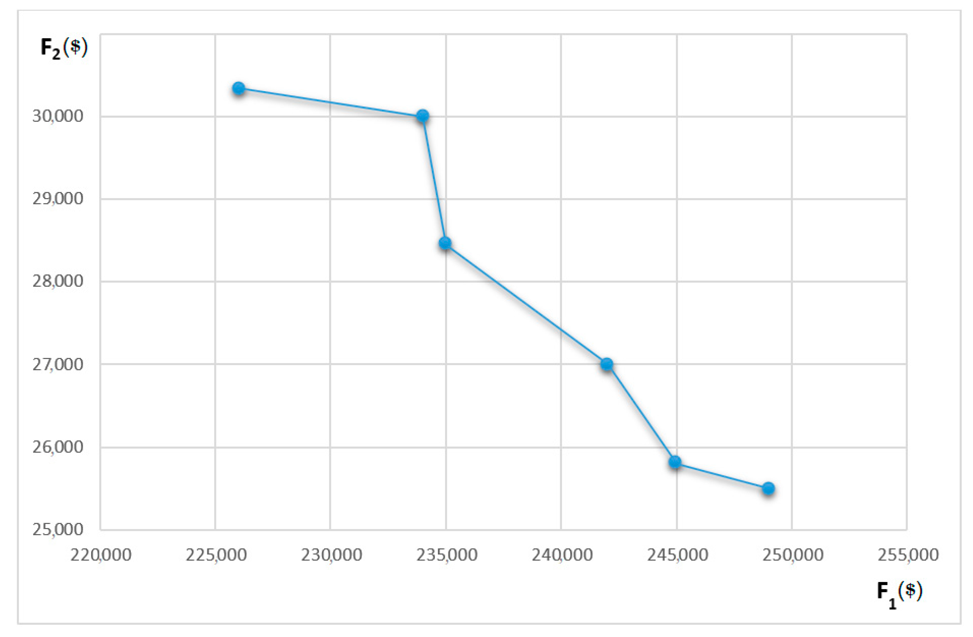
The solutions provided by NSGA-II are Pareto solutions. During the resolution of the problem, the best front of NSGA-II provides six solutions shown in Figure 13, where F1 represents the cost of the open gates on the road and F2 represents the T.U.C. Two solutions were used for the discussion; solution 1 had the minimum cost of the open gates on the road, and solution 2 had the minimum T.U.C. of each vehicle type. Table 6 and Table 7 present the numbers of open gates provided by the first and the second solutions, respectively, and Table 8 presents the T.U.C. of each vehicle type in the first and the second solutions.
Table 6 and Table 7 present the number of open gates in each active charging lane for the first and the second solutions, respectively. Table 8 shows the cost of the open gates and T.U.Cs of each vehicle type for the selected solutions (solutions 1 and 2).
The total number of open gates in the first solution was 226 with the main entry and exit gates, and the total cost was 226,000. Compared with the second solution, which gave 249,000 as the cost of the open gates, the first solution found the best case for the open gates on the road. However, the second solution had the minimum T.U.C of the vehicles compared with the first. It is remarked that, when the T.U.C decreased in the second solution, the total number of open gates in the road increased compared with the first solution. This phenomenon is logical, because if the T.U.C is reduced in the second solution, each vehicle type uses a set of gates to minimize its T.U.C. Owing to the heterogeneity of the vehicles, the set of gates used by each vehicle type differed from one vehicle to another. For this purpose, the number of gates increased in this case (second solution), which improved the reality of the results. On the other hand, when the number of open gates on the road decreased (solution 1), the search space for gates to be used for each vehicle decreased; because of this, the T.U.C of some vehicles increased (solution 2).
Table 9 presents the cost of the total gates on the road and the T.U.C of each vehicle if the gates are installed only at the beginning and the end of each active segment in the infrastructure found in [3] (Table 5), which is noted as solution 0.
The open gate cost in solution 0 was 215,000, which was a little lower than the costs found for solutions 1 and 2. This result was expected, because solution 0 was developed in a way to minimize the number of active segments, which minimized the number of open gates placed at the beginning and end of the active segments, demonstrating the reality of the results found by the NSGA-II. On the other hand, there was a significant rise in the T.U.C in solution 0, demonstrating the efficacy of the results. The T.U.C increased in solution 0 because the vehicles in this solution would be required to use the active segments completely, even if their battery saturated before the principal exit gate at the end of the segment.
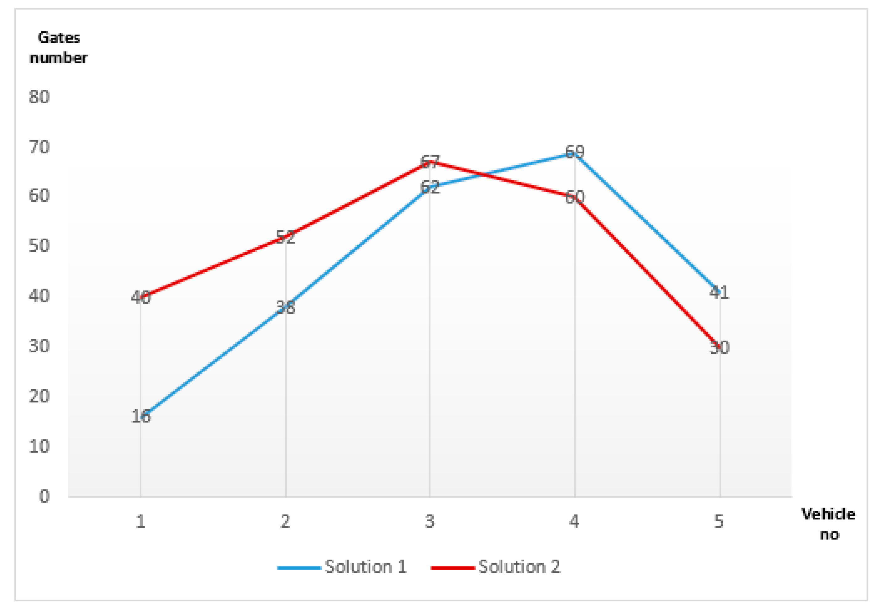
Figure 14 shows the use of the open gates according to the number of vehicles in solutions 1 and 2. In solution 1, 69 gates were used by four vehicles, 60 gates were used by three vehicles, 41 gates were used by five vehicles, and the other gates were used by two or one vehicle. Most of the open gates were used by at least three or four vehicles, which corresponds to reality because, if a gate is open, the best case to minimize the number of gates on the road is to have them be usable by all or the maximum number of types of vehicles. In solution 2, 40 gates were used by one vehicle and 52 gates were used by two vehicles; compared with the first solution, the number of gates used by one or two vehicles was higher in the second solution. For this purpose, the second solution provided a lower T.U.C of vehicles because it allowed a somewhat significant number of vehicles to use the gates to minimize their T.U.C; however, the number of open gates comparatively increased in this solution.

5. Conclusions

This work treats the problem of the optimal deployment of the entry and exit gates of wireless electric vehicle charging transmitters on highways. The study considered the T.U.C as a new factor in the problem as electric vehicles’ batteries drain very quickly on highways due to the high speed and the long distance between the origin and the destination, which increases the usage cost of DWCSs for vehicles. The heterogeneity of the battery vehicles adds more difficulty to finding the optimal locations of gates because each has its characteristics. For this purpose, the study introduced a mathematical model with constraints, which aimed to find the best location of a set of gates in the wireless power transmitters that allowed a heterogeneous fleet of vehicles to travel on the highway at the minimum usage cost. The non-dominated sorting genetic algorithm was adopted to solve the problem and demonstrate the model’s application; the paper considered the Morocco highway (Meknes–Fez) as a case study. This work used static data; for example, it was assumed that there was no heavy traffic in the charging lanes, which would influence the time required for a full battery recharge. Therefore, integrating random factors in a stochastic study will be a continuation of this study. Additionally, building mixed wireless charging infrastructure, static and dynamic, would be more challenging, ensuring a vehicle trip with the minimum usage cost.

Author Contributions

Conceptualization, M.B., H.E. and A.E.A.; methodology, M.B. and A.E.A.; software, M.B. and H.E.; validation, M.B., H.E. and A.E.A.; formal analysis, M.B., H.E. and A.E.A.; investigation, M.B. and H.E.; resources, M.B.; data curation, M.B. and H.E.; writing—original draft preparation, M.B. and H.E.; writing—review and editing, M.B.; visualization, A.E.A.; supervision, A.E.A.; project administration, A.E.A.; funding acquisition, A.E.A. All authors have read and agreed to the published version of the manuscript.

Funding

This research received no external funding.

Data Availability Statement

Not applicable.

Conflicts of Interest

The authors declare no conflict of interest.

References

  1. Qiu, C.; Chau, K.T.; Ching, T.W.; Liu, C. Overview of wireless charging technologies for electric vehicles. J. Asian Electr. Veh. 2014, 12, 1679–1685. [Google Scholar] [CrossRef] [Green Version]
  2. Jeong, S.; Jang, Y.J.; Kum, D. Economic analysis of the dynamic charging electric vehicle. IEEE Trans. Power Electr. 2015, 30, 6368–6377. [Google Scholar] [CrossRef]
  3. Bourzik, M.; Hilali Alaoui, A.E.L. The Optimal location of the wireless charging infrastructure for electric vehicles with heterogeneous batteries in the highway. Int. J. Logist. Syst. Manag. 2022; in press. [Google Scholar]
  4. Rim, C.T.; Mi, C. Wireless Power Transfer for Electric Vehicles and Mobile Devices; John Wiley & Sons: Hoboken, NJ, USA, 2017. [Google Scholar]
  5. Alwesabi, Y.; Wang, Y.; Avalos, R.; Liu, Z. Electric bus scheduling under single depot dynamic wireless charging infrastructure planning. Energy 2020, 213, 118855. [Google Scholar] [CrossRef]
  6. Jang, Y.J.; Jeong, S.; Lee, M.S. Initial energy logistics cost analysis for stationary, quasi-dynamic, and dynamic wireless charging public transportation systems. Energies 2016, 9, 483. [Google Scholar] [CrossRef] [Green Version]
  7. Liu, Z.; Song, Z. Robust planning of dynamic wireless charging infrastructure for battery-electric buses. Transp. Res. Part C Emerg. Technol. 2017, 83, 77–103. [Google Scholar] [CrossRef]
  8. Liu, Z.; Song, Z. Dynamic charging infrastructure deployment for plug-in hybrid electric trucks. Transp. Res. Part C Emerg. Technol. 2018, 95, 748–772. [Google Scholar] [CrossRef]
  9. Chen, Z.; Xiong, R.; Cao, J. Particle swarm optimization-based optimal power management of plug-in hybrid electric vehicles considering uncertain driving conditions. Energy 2016, 96, 197–208. [Google Scholar] [CrossRef]
  10. Chen, Z.; Yin, Y.; Song, Z. A cost-competitiveness analysis of charging infrastructure for electric bus operations. Transp. Res. Part C Emerg. Technol. 2018, 93, 351–366. [Google Scholar] [CrossRef]
  11. Fuller, M. Wireless charging in California: Range, recharge, and vehicle electrification. Transp. Res. Part C Emerg. Technol. 2016, 67, 343–356. [Google Scholar] [CrossRef]
  12. Mouhrim, N.; El Hilali Alaoui, A.; Boukachour, J. Pareto efficient allocation of in-motion wireless charging infrastructure for electric vehicles in a multipath network. Int. J. Sustain. Transp. 2019, 13, 419–432. [Google Scholar] [CrossRef]
  13. Elbaz, H.; Elhilali Alaoui, A. Optimal Installation of the Power Transmitters in the Dynamic Wireless Charging for Electric Vehicles in a Multipath Network with the Round-Trip Case. Int. J. Intell. Transp. Syst. Res. 2022, 20, 46–63. [Google Scholar] [CrossRef]
  14. Sun, X.; Chen, Z.; Yin, Y. Integrated planning of static and dynamic charging infrastructure for electric vehicles. Transp. Res. Part D Transp. Environ. 2020, 83, 102331. [Google Scholar] [CrossRef]
  15. Ko, Y.K.; Oh, Y.; Ryu, D.Y.; Ko, Y.D. Optimal Deployment of Wireless Charging Infrastructure for Electric Tram with Dual Operation Policy. Vehicles 2022, 4, 681–696. [Google Scholar] [CrossRef]
  16. Anand, R.; Aggarwal, D.; Kumar, V. A comparative analysis of optimization solvers. J. Stat. Manag. Syst. 2017, 20, 623–635. [Google Scholar] [CrossRef]
  17. Seshadri, A. A Fast Elitist Multiobjective Genetic Algorithm: NSGA-II; MATLAB Central. 2006, Volume 182. Available online: https://web.njit.edu/~{}horacio/Math451H/download/Seshadri_NSGA-II.pdf (accessed on 13 January 2022).
  18. Carlucci, S.; Cattarin, G.; Causone, F.; Pagliano, L. Multi-objective optimization of a nearly zero-energy building based on thermal and visual discomfort minimization using a non-dominated sorting genetic algorithm (NSGA-II). Energy Build. 2015, 104, 378–394. [Google Scholar] [CrossRef] [Green Version]
  19. Morell, J.Á.; Dahi, Z.A.; Chicano, F.; Luque, G.; Alba, E. Optimising Communication Overhead in Federated Learning Using NSGA-II. In International Conference on the Applications of Evolutionary Computation (Part of EvoStar); Springer: Cham, Switzerland, 2022; pp. 317–333. [Google Scholar]
  20. Da Silva, D.F.; Okada, L.F.; Assunção, W.K.; Colanzi, T.E. Intensifying the search-based optimization of product line architectures with crossover operators. Empir. Softw. Eng. 2022, 27, 166. [Google Scholar] [CrossRef]
  21. Chen, D.; Song, M. An improved knowledge-informed NSGA-II for multi-objective land allocation (MOLA). Geo-Spat. Inf. Sci. 2018, 21, 273–287. [Google Scholar]
  22. Chatelain, C.; Adam, S.; Lecourtier, Y.; Heutte, L.; Paquet, T. A multi-model selection framework for unknown and/or evolutive misclassification cost problems. Pattern Recognit. 2010, 43, 815–823. [Google Scholar] [CrossRef] [Green Version]
  23. Liu, J.; Chen, X. An improved NSGA-II algorithm based on crowding distance elimination strategy. Int. J. Comput. Intell. Syst. 2019, 12, 513–518. [Google Scholar] [CrossRef] [Green Version]
  24. Ghasemi, A.R.; Hajmohammad, M.H. Multi-objective optimization of laminated composite shells for minimum mass/cost and maximum buckling pressure with failure criteria under external hydrostatic pressure. Struct. Multidiscip. Optim. 2017, 55, 1051–1062. [Google Scholar] [CrossRef]
  25. Chu, X.; Yu, X. Improved crowding distance for NSGA-II. arXiv 2018, arXiv:1811.12667. [Google Scholar]
Figure 1. Dynamic wireless charging system.
Wevj 13 00227 g001
Figure 2. Highway with a DWCS.
Wevj 13 00227 g002
Figure 3. Structure of the road.
Wevj 13 00227 g003
Figure 4. Highway with active and inactive segments.
Wevj 13 00227 g004
Figure 5. Example of entry and exit gates of a DWCS road.
Wevj 13 00227 g005
Figure 6. Highway with active and inactive charging lanes.
Wevj 13 00227 g006
Figure 7. Highway with potential gates.
Wevj 13 00227 g007
Figure 8. Calculation of crowding distance in NSGA-II.
Wevj 13 00227 g008
Figure 9. Example of the open gate matrix.
Wevj 13 00227 g009
Figure 10. Example of the first type of crossover procedure.
Wevj 13 00227 g010
Figure 11. Example of the mutation procedure.
Wevj 13 00227 g011
Figure 12. The Morocco highway (Meknes “A”–Fez “B”).
Wevj 13 00227 g012
Figure 13. Best front of solutions.
Wevj 13 00227 g013
Figure 14. Use of open gates according to the number of vehicles.
Wevj 13 00227 g014
Table 1. Vehicle data.
Vehicle 1Vehicle 2Vehicle 3Vehicle 4
Energy   supply   rate   in   each   segment   ( k w ) 4.2355.5
Energy   consumption   rate   ( k w h / 100   k m ) 25.219.619.534.7
E u p α 817.813.820
E l o w α 2.73.85.74
Unit cost for using the DWCS road12.58.51014
Table 2. Lane data.
Table 2. Lane data.
Lane NumberLengthLane StatusPotential Gates Number
1500Inactive0
2750Active4
3500Inactive0
4500Active4
5500Inactive0
61000Active4
7750Inactive0
8500Active4
9500Inactive0
101000Active4
11250Inactive0
12250Active4
13500Inactive0
Table 3. Results for each objective.
Minimizing the T.U.CMinimizing the Open Gates
Total cost of open gates on the road19,0000
T.U.C of vehicle 1137.5312.5
T.U.C of vehicle 2127.5212.5
T.U.C of vehicle 3150250
T.U.C of vehicle 4126294
Table 4. Active and inactive lanes.
Seg. NoSeg. StatusLane No.Lane StatusSeg. NoSeg. StatusLane No.Lane Status
1-2Inactive 1 Inactive144Inactive57Inactive
3-4-5-6-7-8-9-10Active2Active145-146-147-148-149Active58Active
11-12Inactive3Inactive150Inactive59Inactive
13-14Active4Active151Active60Active
15Inactive5Inactive152Inactive61Inactive
16Active6Active153Active62Active
17Inactive7Inactive154Inactive63Inactive
18-19-20-21Active8Active155-156-157Active64Active
22Inactive9Inactive158Inactive65Inactive
23Active10Active159-160-161Active66Active
24Inactive11Inactive162Inactive67Inactive
25-26Active12Active163-164-165-166-167-168Active68Active
27Inactive13Inactive169Inactive69Inactive
28Active14Active170Active70Active
29Inactive15Inactive171Inactive71Inactive
30Active16Active172-173Active72Active
31Inactive17Inactive174Inactive73Inactive
32Active18Active175Active74Active
33Inactive19Inactive176Inactive75Inactive
34-35-36-37-38-39-40Active20Active177Active76Active
41Inactive21Inactive178Inactive77Inactive
42-43Active22Active179-180Active78Active
44-45Inactive23Inactive181Inactive79Inactive
46-47-48-49Active24Active182-183Active80Active
50Inactive25Inactive184Inactive81Inactive
60-70-71-72Active26Active185Active82Active
73-74Inactive27Inactive186Inactive83Inactive
75-76Active28Active187Active84Active
77-78-79Inactive29Inactive188Inactive85Inactive
80-81-82-83Active30Active189-190-191-192Active86Active
84-85Inactive31Inactive193-194Inactive87Inactive
86-87Active32Active195-196-197Active88Active
88Inactive33Inactive189-190Inactive89Inactive
89-90-91-92-93-94Active34Active191-192-193-194Active90Active
95Inactive35Inactive195-196Inactive91Inactive
96-97-98-99Active36Active197-198-199-200-201-202-203-204-205Active92Active
100Inactive37Inactive 206-207Inactive93Inactive
101-102-103Active38Active208-209-210Active94Active
104Inactive39Inactive211Inactive95Inactive
105-106-107-108-109-110-111-112-113Active40Active212-213Active96Active
114-115Inactive41Inactive214Inactive97Inactive
116-117-118Active42Active215-216-217Active98Active
119Inactive43Inactive218Inactive99Inactive
120-121-122-123-124-125Active44Active219-220-221-222-223-224-225Active100Active
126Inactive45Inactive226-227Inactive101Inactive
127Active46Active228-229-230-231Active102Active
128Inactive47Inactive232Inactive103Inactive
129-130Active48Active233-234Active104Active
131-132Inactive49Inactive235Inactive105Inactive
133-134Active50Active236-237-238-139Active106Active
135Inactive51Inactive240Inactive107Inactive
136Active52Active
137Inactive53Inactive
138-139-140Active54Active
141Inactive55Inactive
142-143Active56Active
Table 5. Vehicle data.
Battery
Capacity
I b a t α ( k w )
Energy Supply RateEnergy Consumption
Rate
( k w h / 100   k m )
Unit Cost for Using the DWCS Road
Vehicle 17.61.129.513.5
Vehicle 242.20.917.811
Vehicle 311.61.330.617
Vehicle 418.40.419.59
Vehicle 5161.225.815
Table 6. Number of open gates in each charging lane for solution 1.
Lane No.PG NumberOpen Gates NumberLane No.PG NumberNumber of Open Gates
240656102
410258253
6506050
82036250
105164152
1210266152
145068304
16507050
185172102
203557450
221027650
2420578102
262038050
281038250
302068451
3210186203
3430688152
3620590205
3815492455
4045794152
4215596101
4430498152
4650100354
48101102203
50102104101
5250106204
54153
Table 7. Number of open gates in each charging lane for solution 2.
Lane No.PG NumberNumber of Open GatesLane No.PG NumberNumber of Open Gates
240856104
410458252
6506051
82046250
105164152
1210266153
145068304
16507051
185172103
203577451
221037650
2420678102
262038051
281048250
302078451
3210386202
3430688152
3620690206
3815392457
4045894151
4215396101
4430598151
4651100355
48101102202
50103104102
5251106203
54153
Table 8. T.U.C of each vehicle type.
T.U.C of Solution 1T.U.C of Solution 2
Vehicle 170206001
Vehicle 241294059
Vehicle 378036038
Vehicle 439603010
Vehicle 574256393
Table 9. T.U.Cs of the vehicles and the open gates cost in solution 0.
T.U.COpen Gate Cost
Vehicle 112,920215,000
Vehicle 28514
Vehicle 315,096
Vehicle 46960
Vehicle 513,230
Publisher’s Note: MDPI stays neutral with regard to jurisdictional claims in published maps and institutional affiliations.