Article

The Integrated Kinetic Energy Recoup Drive (i-KERD): An Optimized Powertrain for EVs, HEVs and FCEVs

1
Changzhou Haike New Energy Tech Co., Ltd., Changzhou 213001, China
2
Department of Automotive Engineering, Shandong University of Technology, Zibo 255000, China
*
Author to whom correspondence should be addressed.
World Electr. Veh. J. 2022, 13(1), 8; https://doi.org/10.3390/wevj13010008
Submission received: 25 October 2021 / Revised: 11 December 2021 / Accepted: 22 December 2021 / Published: 28 December 2021

Abstract

:
In this paper, a particular form of flywheel hybrid powertrain, namely, the Integrated Kinetic Energy Recoup Drive (i-KERD) is fully explored and its applications for EVs, HEVs and FCEVs in recent years to show the energy-savings and performance enhancement potential of this innovative powertrain technology. It is shown that the i-KERD is a small highspeed flywheel integrated into an e-CVT, or power-split hybrid drive. Under NEDC or WLTC, typically it can achieve some 40% energy savings and >50% gain in 0–100 kph acceleration due to effective regenerative braking mechanism of the integrated flywheel power system. In addition to its “peak-shaving” capability, the highly-efficient, long-life flywheel power on-board, is able to keep the kinetic energy of the vehicle fully recycled, rather than dissipated during braking. The i-KERD technology has also been applied to urban railway transportation (i.e., underground railway) and off-road heavy construction equipment, where regenerative braking plays a great role on energy efficiency.

1. Introduction

Flywheel hybrid powertrain, or flywheel power for short, is a new form of mechanical-electrical hybrid powertrain system arising from the need to recover kinetic energy in road vehicles and other mobile heavy machinery equipment by use of a high-speed flywheel on-board and integrated into the powertrain system [1,2]. Unlike flywheel energy storage systems (ESSs), the high speed flywheels here are for short-term storage of the kinetic energy and a high level of braking power is desirable, thus making it possible to use small and simple flywheels for widespread application in electric/hybrid vehicles and heavy machinery equipment. By matching the power output characteristics of the on-board flywheel power system with that of the vehicle/equipment, optimization of the on-board powertrain is obtained, resulting in substantial reduction of the power ratings of the electric drive systems and the amount of energy consumed on-board [3,4,5,6,7,8,9,10,11,12].
A surge of interest in this new and innovative powertrain technology, mainly in Europe, peaked around 2010–2015, especially in motor racing and urban buses. In Europe, flywheel power has been used successfully in the World Endurance Championship, including Le Man. The technology has been recognized by more and more industry authority as the mainstream hybrid powertrain technology of next-generation energy-saving vehicle because of its excellent system efficiency, dynamic performance and cost-effectiveness. It provides technical and economic feasibility for the popularization and wide-spread application of energy-saving and new energy vehicles. Major European auto manufacturers such as Audi, Porsche and Volvo have been rapidly following up on developing commercial products and have stimulated R and D efforts of major Tier Ones such as GKN, Torotrak, PunchPower, and auto engineering companies such as Ricardo [13,14,15,16].
In December 2011, the Oak Ridge National Laboratory in the United States made public its full evaluation of the flywheel power technology. It indicated that flywheel power technology is particularly suitable for hybrid electric drive systems. Flywheel can effectively assist hybrid drive systems to meet the high power demand of hybrid vehicle during accelerating/braking [1]. In the process of regenerative braking, the power and efficiency of a flywheel in absorbing kinetic energy can be far higher than that of a battery of comparable size and cost. The most effective use of a flywheel power system is to provide sufficient energy reserve while providing high power output, so as to fulfill the task of auxiliary power for load-leveling, or “peak-shaving”. Therefore, flywheel power systems can meet or exceed the performance objectives related to on-board powertrains (discharge power, regeneration power, specific power, power density and weight and volume, etc.) compared to battery and/or super capacitors, in more balanced and optimal way. However, due to various reasons, this new technology has been largely overlooked in the US as well as Japan in recent years.
In this paper, a particular form of flywheel power, namely, the Integrated Kinetic Energy Re cup Drives (i-KERD) is fully explored and its applications for EVs, HEVs and FCEVs by the authors’ team in recent years covered to show the performance enhancement potential of this innovative powertrain technology [17,18,19]. It is shown that the i-KERD is a small high-speed flywheel integrated into an e-CVT, or power-split drive. Under NEDC or WLTC, it is able to achieve some 40% energy savings and >50% gain in 0–100 kph acceleration. These extraordinary performance gains have been proved for various EV, HEV and FCEV applications in prototype vehicular testings, and test results from a range-extended light truck will be presented and fully discussed in this paper.

2. Operating Principles of the i-KERD System

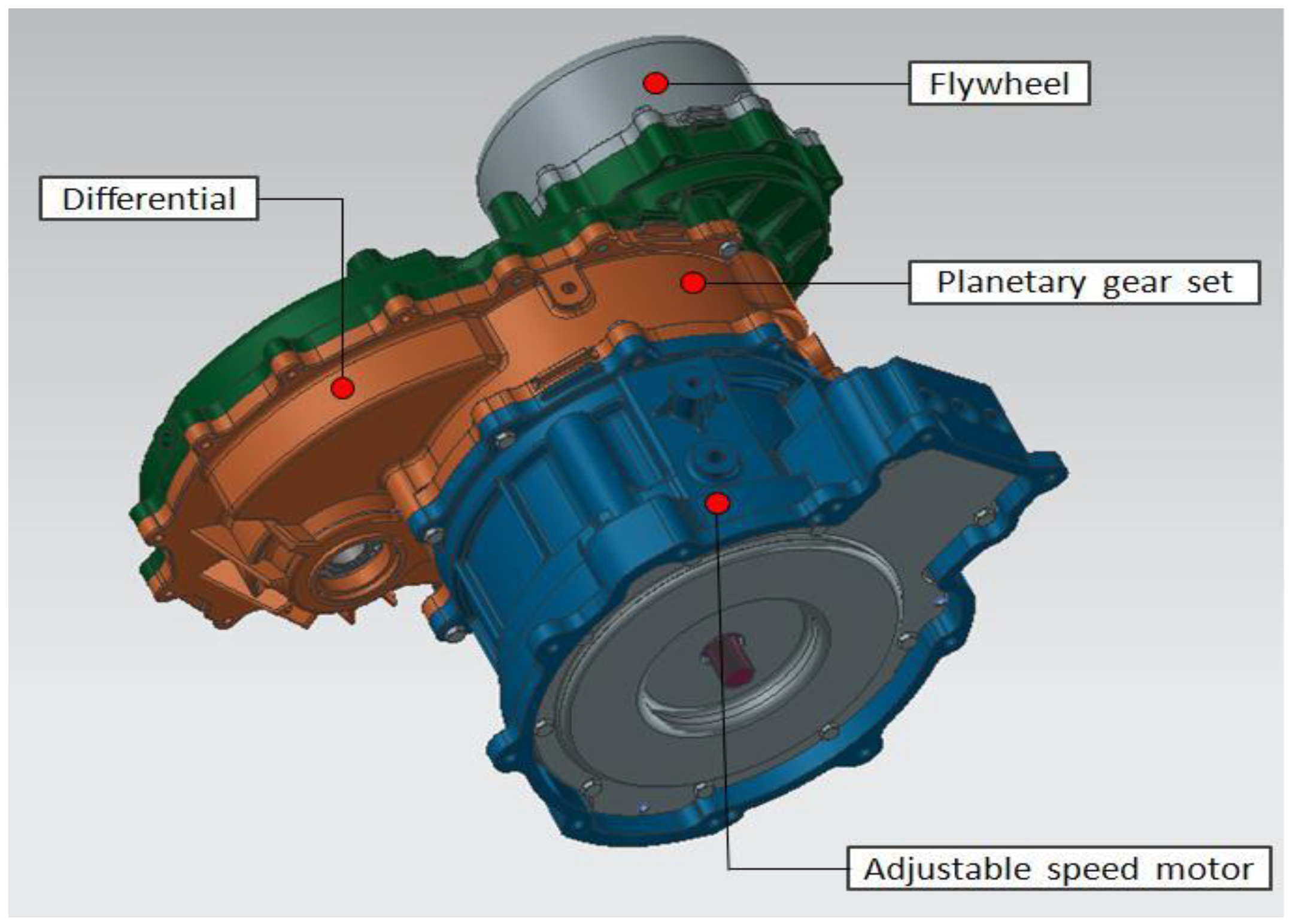
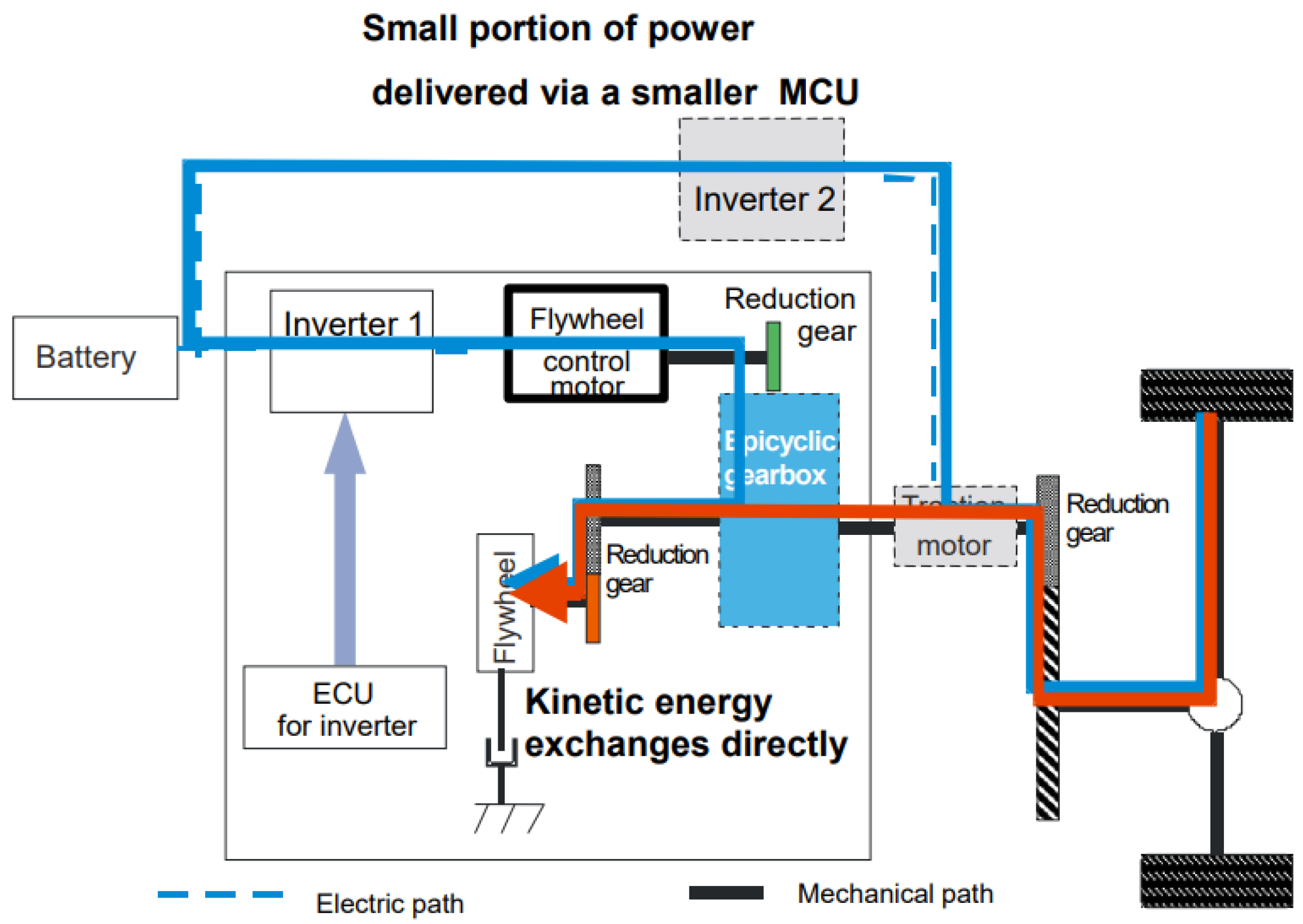
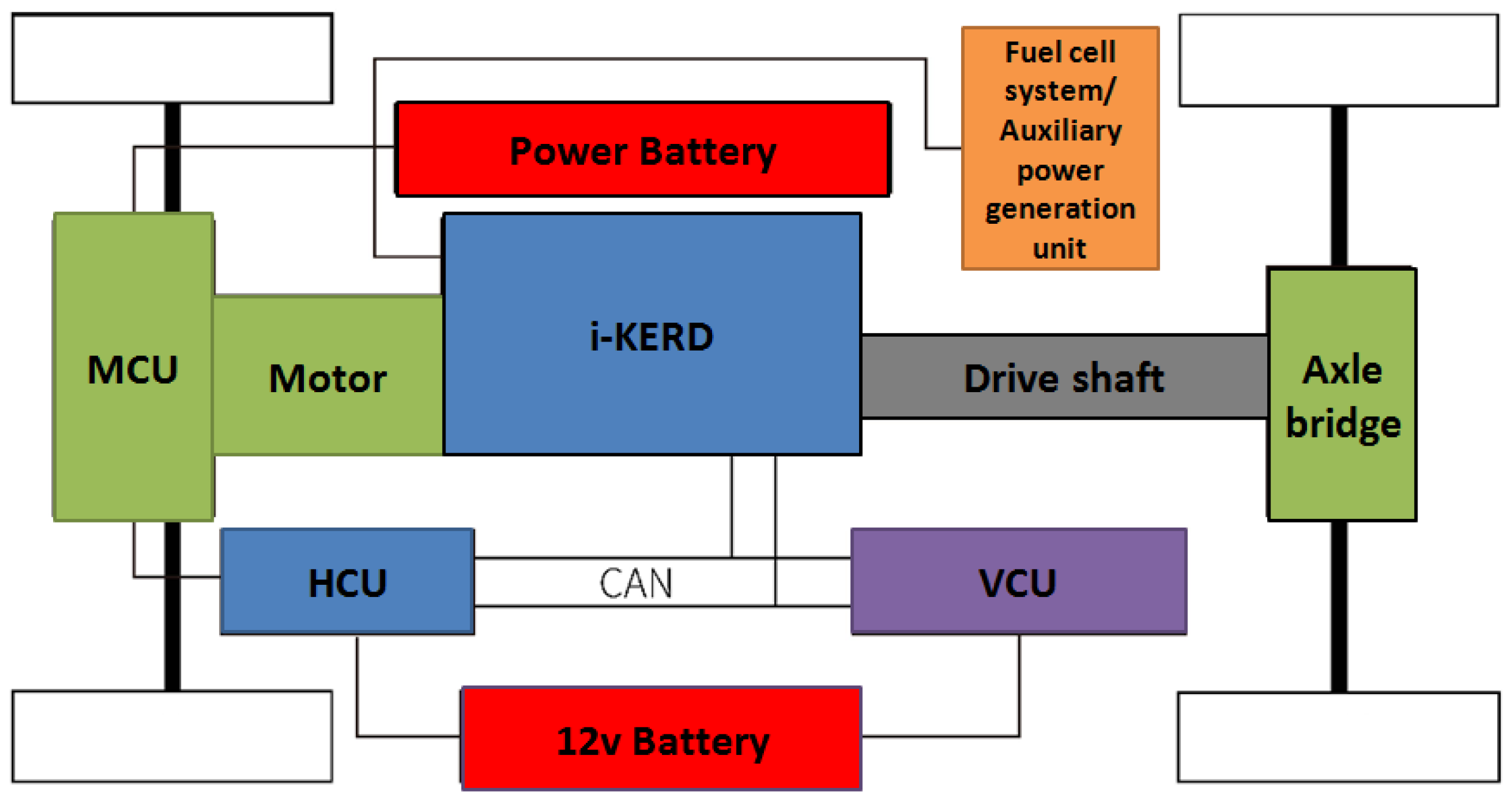
2.1. i-KERD Configuration and System Schematic

Recently, significant attention has been directed to the field of kinetic energy recovery of new-energy vehicles as it means a great deal in enhancing the powertrain system efficiency. It is known that the regenerative braking efficiency of the electric drive system on-board is very low (usually in the lower teens of percentage) due to various practical reasons. Among the many innovative new solutions, flywheel stands out as highly promising in terms of energy efficiency and cost-effectiveness.
The flywheel power system combines flywheel ESS technology and advanced transmission control technologies, such as CVT and electric continuously variable transmission (e-CVT), to give full play to the distinct advantage of the compact, high-speed flywheel. A flywheel power system stores energy in the flywheel in the form of mechanical energy, and its power density can be much higher than that of the existing on-board power system using battery. Unlike the well-known battery and supercap scheme of “peak-shaving”, it not only effectively solves the problem of power limitation of the electric drive system on-board and battery inefficiencies during acceleration/braking, but also directly couples the mechanical output of the flywheel to the drivetrain. This unique advantage greatly improves the energy efficiency of regenerative braking and, at the same time, the acceleration performance of the vehicle as well, resulting in much improved cost-effectiveness and optimization of the powertrain system. In addition to its “peak-shaving” capability, the highly-efficient, and adequately-sized flywheel on-board is able to keep the kinetic energy of the vehicle fully and effectively recycled, rather than dissipated during braking, while the main motor drive needs only to provide power to overcome rolling and windage resistance of the vehicle, which is usually only a fraction of the total peak power required by the vehicle.
As illustrated in Figure 1, the i-KERD consists of a gearbox with a planetary gear-set, which connects a high-speed flywheel and an adjustable speed PM motor, a typical embodiment of the e-CVT drive with the flywheel replacing a second motor. When charged with kinetic energy, the flywheel will behave like a motor under active control of the PM motor through the planetary gear-set. Motoring and regenerative torque is thus produced if:
n s + k n r = ( 1 + k ) n c
where
  • ns—sun speed;
  • nr—ring speed;
  • nc—carrier speed;
  • k—gear ratio of ring-to-sun (k > 1)
Figure 1. 3-D model of the i-KERD assembly.
Wevj 13 00008 g001
And the torques of each part of the planetary gear-set satisfies the following equation:
T s 1 = T r k = T c ( 1 + k )
where
  • Ts—torque of sun wheel;
  • Tr—ring gear torque;
  • Tc—carrier torque.
Shown in Figure 2 is the system structure of the flywheel power system i-KERD, where the flywheel and control motor are connected in parallel with the main driving device (driving motor) of the vehicle through the planetary gear-set, which directly adds to the torque of the driving motor at any speed, increasing total power for the vehicle.
The main drive power and flywheel power can achieve better torque distribution control and power-split in the power-plant, so as to achieve the balanced effect of energy-savings and dynamic performance. In the process of vehicle deceleration, and the braking energy is directly recovered and stored in the form of kinetic energy in the flywheel, which is far more efficient and effective than the motor-battery energy recovery scheme affected by chemical reaction of the battery at high charge–discharge rates. When the vehicle starts and accelerates, it directly transfers power and energy to drive the wheels in the form of output torque, which also reduces the power demand of the main drive motor. In the process of acceleration and deceleration, the main drive power and flywheel power can provide better torque distribution control and efficient use of flywheel kinetic energy, and reduce the main drive (main motor) and battery power output, resulting in a more effective energy recovery and optimized powertrain system.

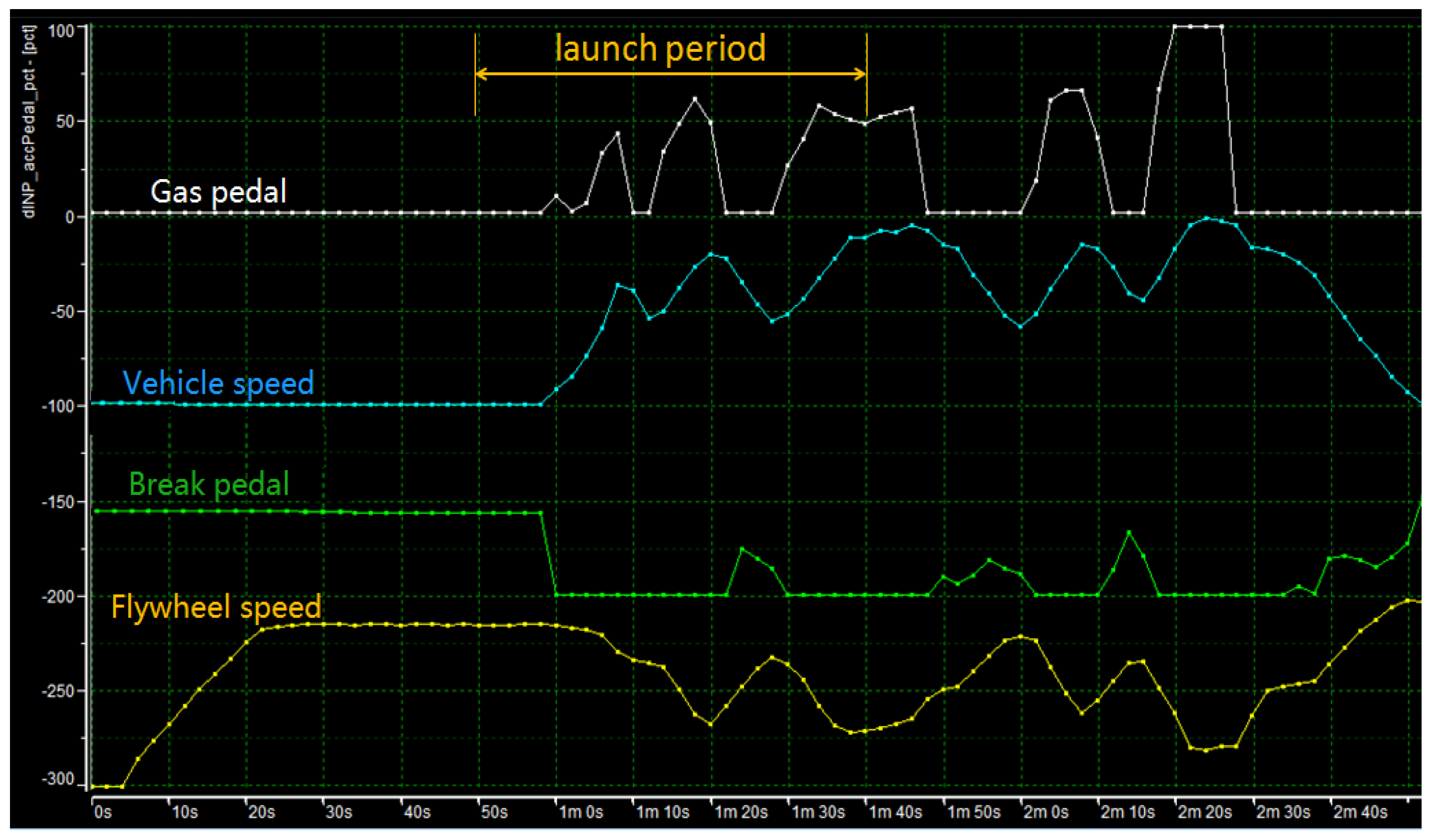
2.2. Operation of the i-KERD during Vehicle Launch/Braking

Based on the operating principle of power-split of e-CVT, we can now analyze the flywheel power system i-KERD in the process of starting/accelerating and braking/decelerating. While controlling the flywheel speed motor to act as a differential, we dynamically adjusted the output torque of the flywheel according to the driver’s intent, and controlled the combined torque on top of the output torque of the main motor at different speeds until the flywheel speed is zero, when it is fixed at zero speed by one-way clutch. At this time, the planetary gear is equivalent to a reducer, and the output torque of the control motor is directly superimposed (in parallel) on the output torque of the main motor through the speed ratio k.
When the vehicle starts, climbs and accelerates, the flywheel power system has high power output with full energy stored, which can provide surging auxiliary power complementing the main power from the battery source, meeting high power demand to accelerate the inertia of the vehicle. This also ensures that the main power works at the optimal efficiency point. Because a considerable part of the on-board power of the vehicle is realized by the flywheel power system, the power ratings of the main power can be reduced, and the energy consumption also lowered while maintaining the same dynamic performance. Note also that unlike battery source limited by the discharge depth (thus life) of the chemical battery, the energy in the flywheel can be completely released into the powertrain, realizing unlimited regenerative braking/recycling of the vehicle kinetic energy, ideally.
When the vehicle idles, the flywheel gets power and energy from the battery system through the flywheel motor to accelerate the flywheel to the preset speed to complete the pre-charging and energy storage. When the vehicle accelerates, the flywheel decelerates to release energy, which accelerates the vehicle together with the driving motor. When the vehicle decelerates, the flywheel effectively recovers the braking energy and stores it in the flywheel for the next vehicle acceleration. By reducing the input and output power of the electric drive system from the battery and consequently the high rate charge and discharge times of the battery, the i-KERD plays the role of peak-shaving and energy-saving and optimize the battery life, especially in fuel-cell/extended-range system, and dynamic response also is greatly reduced.

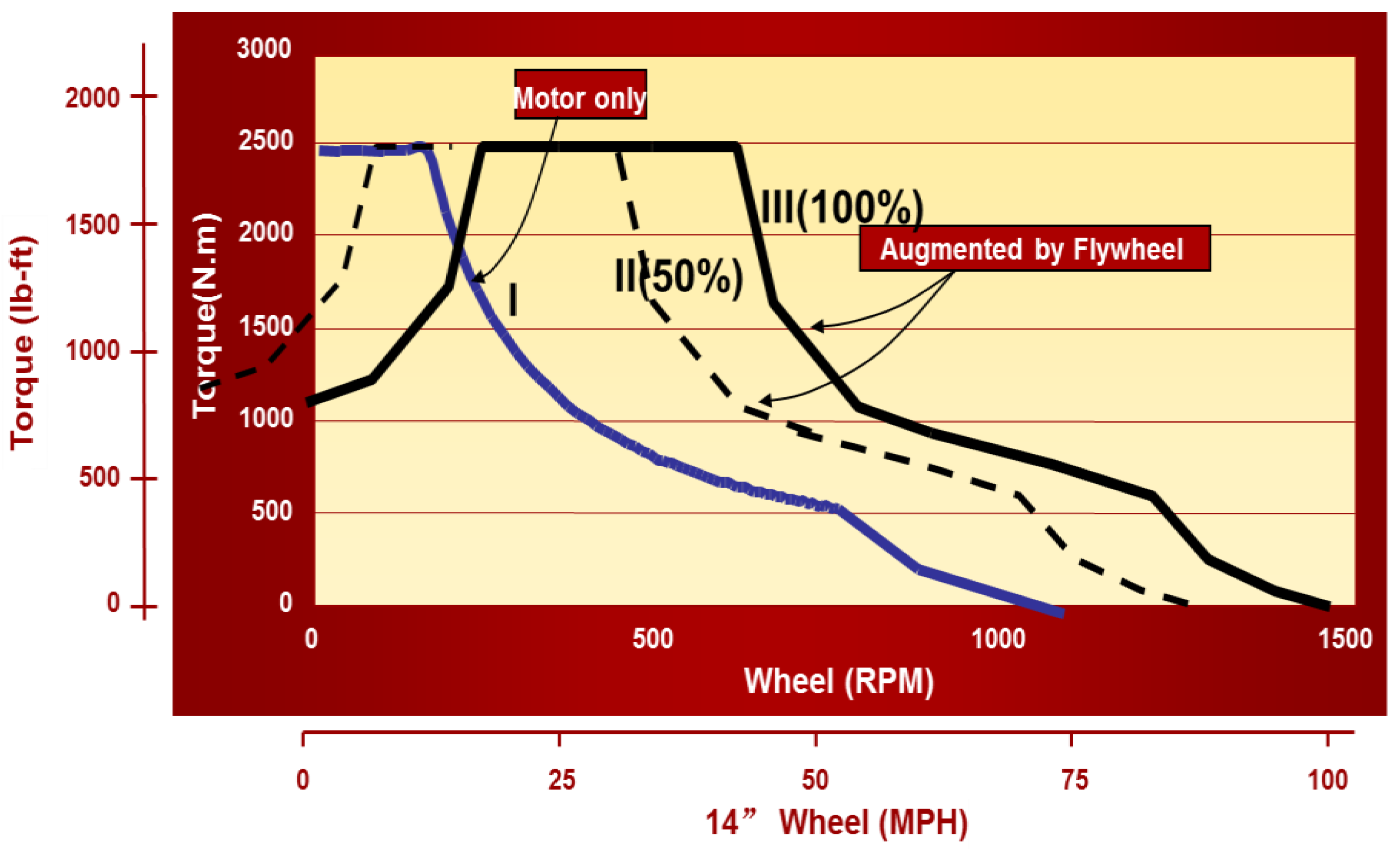
2.3. Dynamic Torque Characteristic of the i-KERD System

From the above analysis, we can now derive the output torque-speed curve of the i-KERD, which is of great importance for vehicle dynamic performance analysis and prediction. It is called “dynamic” torque characteristic for reasons mentioned below.
When the speed of the flywheel is not zero, we can regard the planetary gear connected to the flywheel as a differential. On the premise of meeting the speed relationship of Equation (1), we can directly add the torque of the flywheel motor to the output component. In this way, the output characteristic curve of the flywheel powertrain at different flywheel speeds can be obtained, as shown in Figure 3. It can be clearly seen that this set of characteristic curves is actually the result of the translation of the original characteristic curve of the flywheel control motor to the high speed direction (i.e., the horizontal axis direction). The enhancement or amplification of the output power and torque of the flywheel power system i-KERD as controlled by the flywheel motor can then be determined by the speed or energy state of the flywheel, so it is dynamic, which is the reason for being called dynamic torque characteristic.

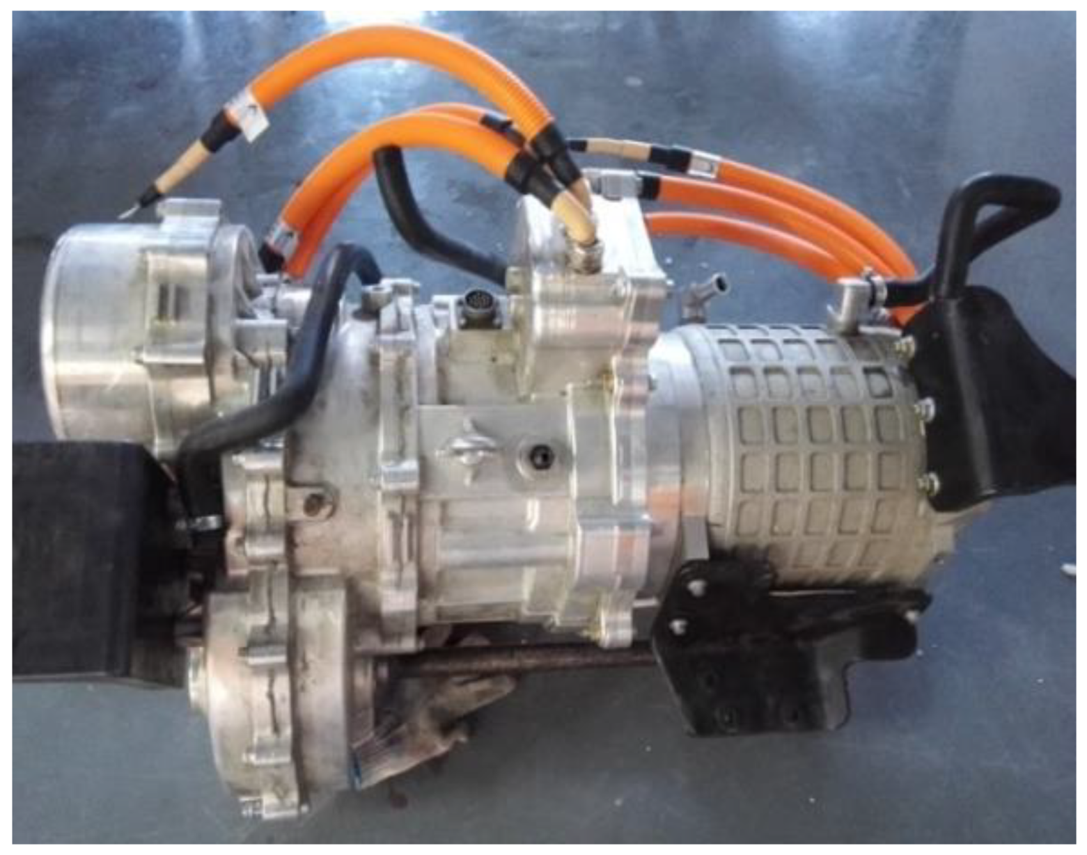
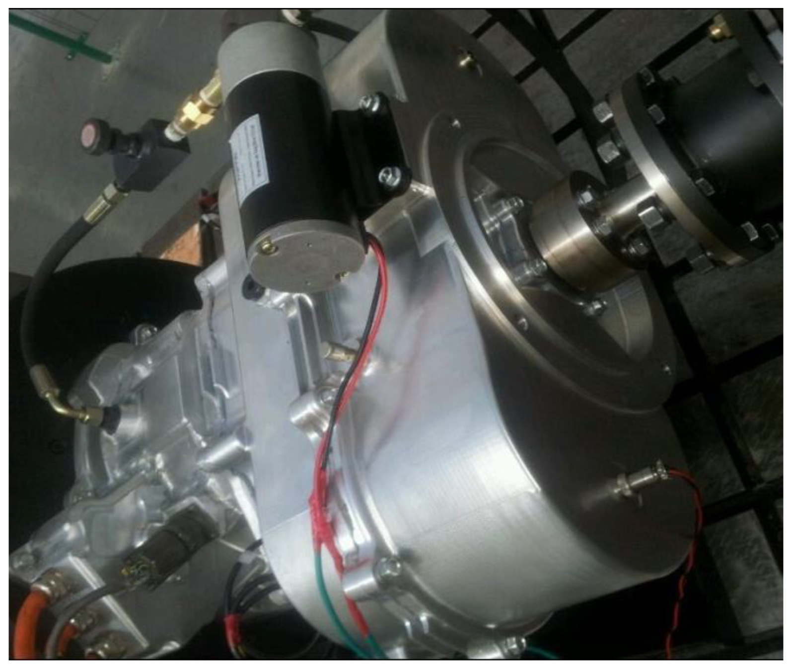
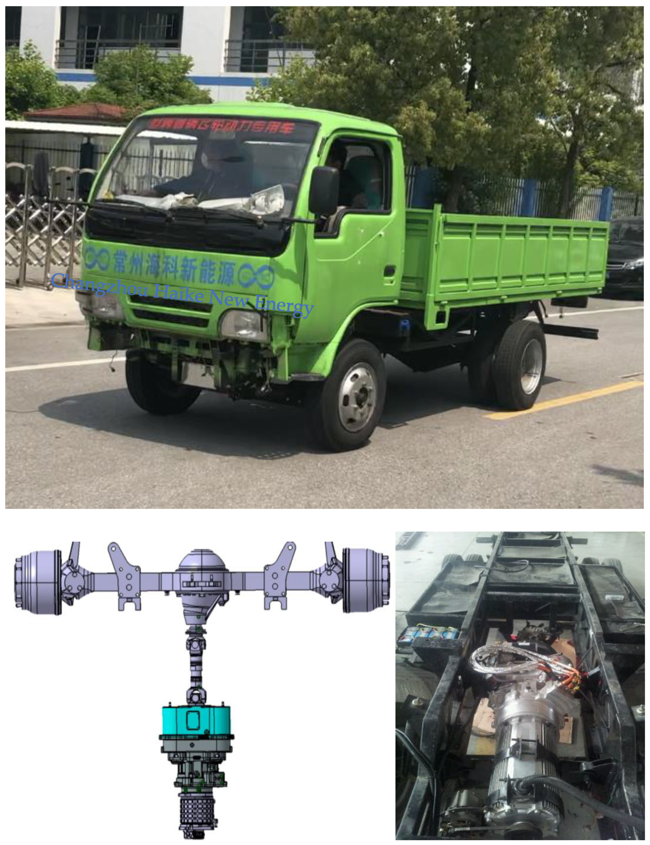
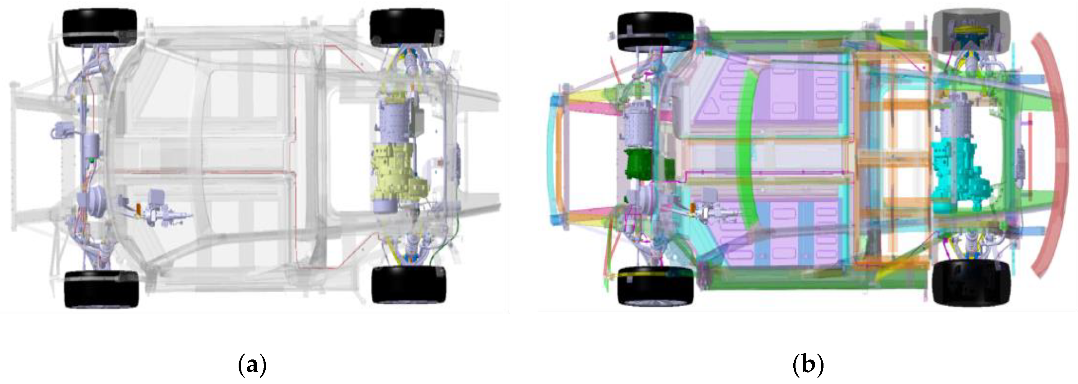
3. Description of Various Applications of the i-KERD

In recent years, we have developed the control strategies and several engineering prototypes of “electro-mechanical” flywheel power system (i-KERD), beside the range-extended EV light truck to be fully described in Section 4. In each case, flywheel, control motor and vehicle transmission system are connected through planetary gear in various ways, as shown in the diagrams in Figure 4, Figure 5 and Figure 6. The flywheel drive is connected with an axle through an electric continuously variable (e-CVT) system composed of planetary gear and a controlling motor for the flywheel, with a majority of power and energy transmitted mainly mechanically. In general, the system still needs a main motor drive, but the power ratings of the electric drive system can be reduced to a fraction of the total power and energy of the system [18,19]. The system is suitable for all forms of new energy vehicles (pure electric vehicles, hybrid vehicles, fuel cell vehicles), heavy construction machinery and rail transit as well, as long as an electric drive exists.
From 2013 to 2017, we have completed the testing and verification of several models. In 2013, the electromechanical flywheel power system, as shown in Figure 6, was successfully fitted to an electric light truck. In 2016, the flywheel power system as shown in Figure 5 was successfully installed in the pure electric K50 Sports Car model of the Great Wall Huaguan Company, Beijing, China. In 2017, the system was added to the pure electric MPV model-k01 of Guojin Automobile Co., Ltd. Zibo, China. In each case functional testing on test-rig as well as field tests were completed, showing vehicle power performance and energy-saving effect significantly improved as expected [2].

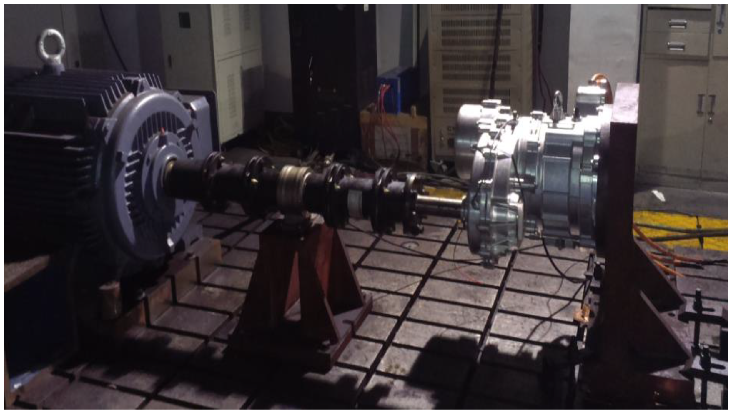
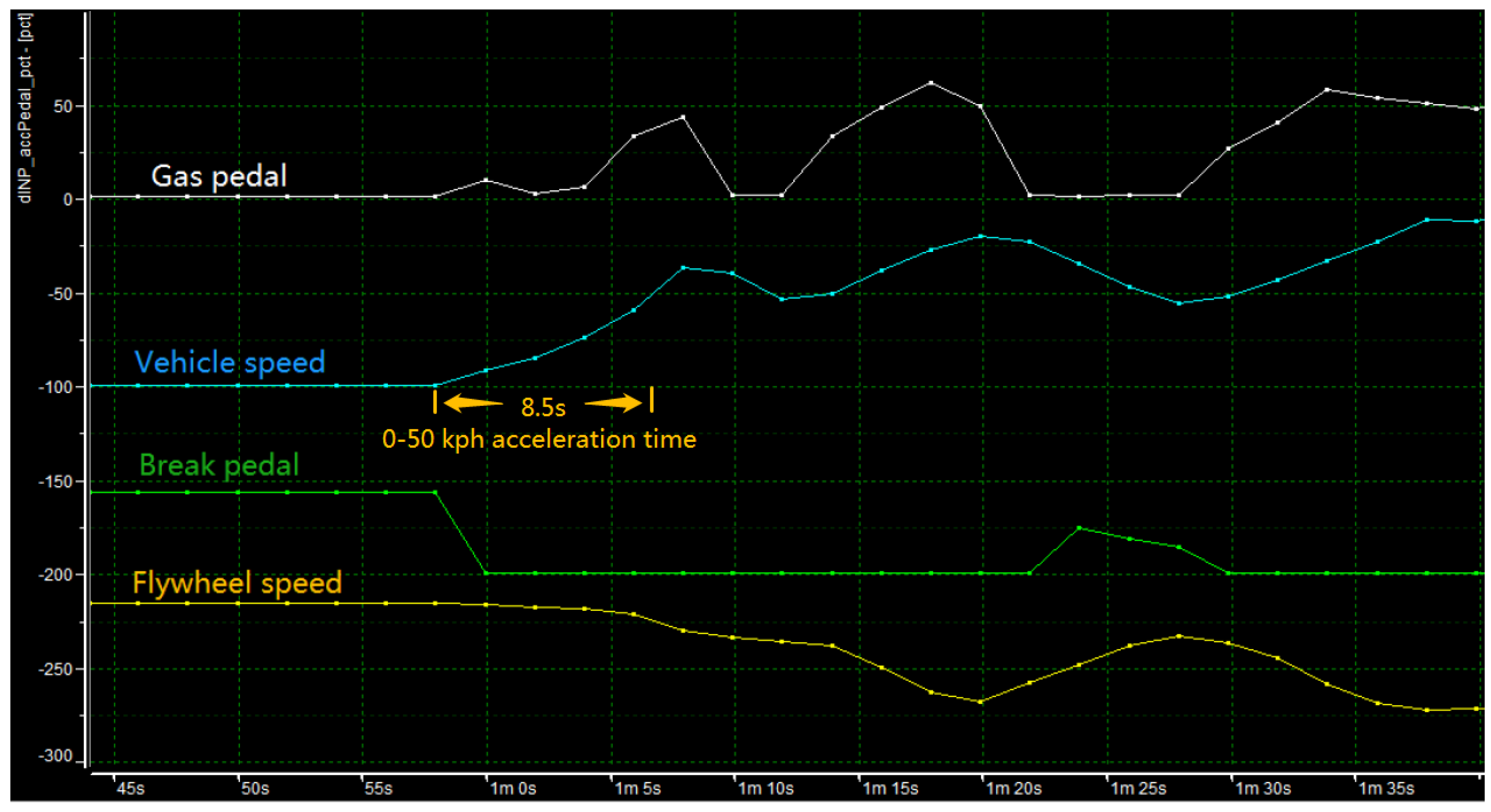
4. Test Results and Analysis

Test results from a range-extended electric light truck (REEV) are presented here and fully discussed in this section. The test vehicle and drive system parameters are shown in Table 1 and Table 2 below, and Figure 7 shows the system configuration of the test vehicle.
The functional test of the flywheel power system was carried out first on the dynamo-meter test bench, as shown in Figure 8. A programmable load is used to simulate the resistance of the vehicle, and the data of the starting/accelerating torque output of the flywheel power system is collected. Under the same output torque required for accelerating, the electric power of the drive system is found to be reduced by some 50%. Under braking conditions, the flywheel participates in the recovery of braking energy, and the peak current of the electric drive system is also reduced by 50%. It can be seen that without reducing the vehicular dynamic performance, the electric power vehicle demand can be greatly reduced through the use of the flywheel power system technology. It can help optimize the power-plant of the new energy vehicles, especially hydrogen fuel-cell, range-extenders, etc. by reducing the power requirements, as well as improving the ability of dynamic response.
The flywheel power system was then tested on-board the pure electric light truck. The power of the original electric drive motor is reduced from 120 kW to 60 kW, as shown in Figure 9. When the vehicle starts and accelerates, the flywheel power system is coupled with the drive motor in parallel as the auxiliary power, and the tested dynamic performance is founded to be consistent with that of the original vehicle.
The start/stop test of the prototype light truck was then repeated in a REEV system set-up, with a 30 kW range-extender installed on board. Different capacities of Lithium battery packs were also tested to find the most cost-effective combination with the range-extender. This range-extender also served to represent a fuel-cell system on-board to prove out the effectiveness of the i-KERD for use in FCEVps.
The recorded wave-forms of the REEV vehicle speed and flywheel speed during a start-up process are compared with the gas pedal and brake pedal signals, as shown in Figure 10. The vehicular launch period is expanded in Figure 11 for a clear view of the dynamic interaction of the flywheel and vehicle speeds, as has been explained in Section 2. It is clear that the vehicle speed follows the gas pedal signal, or the driver’s intent, very well. The flywheel dispatches power (speeds down) in response to the gas pedal and absorbs kinetic energy (speeds up) whenever the vehicle slows down or is braking. The recycling of kinetic energy during regenerative braking mechanism is clearly shown in the figures. The measured acceleration time matches consistently with that of the simulation in Table 2.

5. Conclusions

This paper shows that through the application of the flywheel power system (i-KERD) powertrain optimization and in particular, effective regenerative braking can be achieved. And preliminary on-board testing and verification on a 4.5-ton range-extended electric light truck has proved that the flywheel power system can be highly effective in “peak-shaving”. It can greatly reduce the power and energy demand on the power system on-board during rapid change of dynamics of a vehicle in a real-life driving cycle. In particular, the dynamic characteristics of the range-extender/fuel-cell power system can be significantly improved in the case of range-extended/fuel-cell EVs. The energy-storage of Lithium battery can then be sized to maximize the dynamic response of the system, especially in cold-start. Furthermore, the requirements of peak power and dynamic load-changing capability of the range-extender/fuel-cell system can be greatly reduced, and the system cost-effectiveness and life also greatly improved. In the final analysis, the application of flywheel power system to efficiently recover braking energy can significantly improve the energy efficiency and cost-effectiveness of EVs, REEVs and fuel-cell EVs.

Author Contributions

Conceptualization, Y.L. and M.Y.; methodology, Y.L.; software, C.G.; validation, Y.L., M.Y. and T.W.; formal analysis, T.W.; investigation, M.Y.; resources, Y.L.; data curation, T.W.; writing—original draft preparation, Y.L.; writing—review and editing, C.E.; visualization, M.Y.; supervision, Y.L.; project administration, M.Y.; funding acquisition, Y.L. All authors have read and agreed to the published version of the manuscript.

Funding

The work reported here is supported by MoST, China: National Key R & D Program (Grant #2017YFB0103002).

Institutional Review Board Statement

Not applicable.

Informed Consent Statement

Not applicable.

Acknowledgments

The authors wish to thank Yang Fei, Yiqing Yuan, Shuai Lu, Wensheng Li, Walt Wu and Shuiwen Shen for technical assistance, and Bo Cao for administrative assistance.

Conflicts of Interest

Min Yang, Tao Wang, Chunji Guo and Chris Ellis are employees of the Changzhou Haike New Energy Tech Co., Ltd. The paper reflects the views of the scientists, and not the company.

References

  1. ORNL DoE Report: An Assessment of Flywheel High Power Energy Storage Technology for Hybrid Vehicles. ORNL/TM-2010/280[R/OL]. December 2011. Available online: https://info.ornl.gov/sites/publications/files/Pub31707.pdf (accessed on 1 November 2021).
  2. Liao, Y.; Yang, M. Flywheel ESS and Flywheel Power Drive. In Engineering Handbook of Electric Vehicles; Sun, F., Ed.; China Machine Press: Beijing, China, 2019; Volume 5, ISBN 9787111640172. [Google Scholar]
  3. Jiancheng, Z.; Lipei, H.; Zhiye, C. Research on flywheel energy storage system and its controlling technique. Proc. CSEE 2003, 23, 108–111. [Google Scholar]
  4. Ershad, N.F.; Mehrjardi, R.T.; Ehsani, M. Electro-mechanical EV powertrain with reduced Volt-Ampere rating. IEEE Trans. Veh. Technol. 2019, 68, 224–233. [Google Scholar] [CrossRef]
  5. Robert, H.; Joseph, B. Flywheel batteries come around again. IEEE Spectr. 2002, 39, 46–51. [Google Scholar]
  6. Diego-Ayala, U.; Martinea-Gonzalez, P.; McGlashan, N. The mechanical hybrid vehicle: An investigation of a flywheel-based vehicular regenerative energy capture system. Proc. Inst. Mech. Eng. Part D J. Automob. Eng. 2008, 222, 2087–2101. [Google Scholar] [CrossRef]
  7. Bitterly, J.G. Flywheel technology: Past, present, and 21st century projects. IEEE Aerosp. Electron. Syst. Mag. 1998, 13, 13–16. [Google Scholar] [CrossRef]
  8. Greenwood, C.J. Integration of a Commercial Vehicle Regenerative Braking Driveline; Institution of Mechanical Engineers Conference Publications: Bath, UK, 1986; pp. 127–133. [Google Scholar]
  9. Serrarens, A.F.A.; Shen, S.; Veldpaus, F.E. Control of a flywheel assisted driveline with continuously variable transmission. J. Dyn. Syst. Meas. Control. 2003, 125, 455–461. [Google Scholar] [CrossRef]
  10. Shen, S.; Serrarens, A.F.A.; Steinbuch, M.; Veldpaus, F. Coordinated control of a mechanical hybrid driveline with a continuously variable transmission. JSAE Rev. 2001, 22, 453–461. [Google Scholar] [CrossRef]
  11. Shen, S.; Vroemen, B.; Veldpaus, F. IdleStop and Go: Away to improve fuel economy. Veh. Syst. Dyn. Int. J. Veh. Mech. Mobil. 2006, 44, 449–476. [Google Scholar]
  12. Vroemen, B.; Serrarens, A.F.A.; Veldpaus, F. Hierarchical control of the zero inertia powertrain. JSAE Rev. 2001, 22, 519–526. [Google Scholar] [CrossRef]
  13. Brockbank, C.; Greenwood, C. Fuel economy benefits of a flywheel and CVT based mechanical hybrid for city bus and commercial vehicle applications. SAE Int. J. Commer. Veh. 2010, 2, 115–122. [Google Scholar] [CrossRef]
  14. McDonough, J. System Dynamics Modeling and Development of a Design Procedure for Short-Term Alternative Energy Storage Systems. Ph.D. Thesis, The Ohio State University, Columbus, OH, USA, 2011. [Google Scholar]
  15. Zhang, W.; Yang, H.; Zhu, H. Key technologies and technical bottleneck analysis of flywheel battery systems for electric vehicle. Proc. CSEE 2018, 38, 5568–5581. [Google Scholar]
  16. Bolund, B.; Bernhoff, H.; Leijon, M. Flywheel energy and power storage systems. Renew. Sustain. Energy Rev. 2007, 11, 235–258. [Google Scholar] [CrossRef]
  17. Ellis, C. Kinetic Energy Storage System. U.S. Patent 5,931,249, 3 August 1999. [Google Scholar]
  18. Liao, Y.; Yang, M. Flywheel Power Drives for HEV’s. Chinese Patent ZL201310112569.2, 7 July 2017. [Google Scholar]
  19. Liao, Y.; Yang, M. Energy-Efficient Drives for NEV’s. Chinese Patent ZL201310112572.4, 27 April 2016. [Google Scholar]
Figure 2. System topology of the flywheel power system i-KERD.
Wevj 13 00008 g002
Figure 3. Dynamic external characteristics of the flywheel power system.
Wevj 13 00008 g003
Figure 4. i-KERD in the FF/RR chassis.
Wevj 13 00008 g004
Figure 5. i-KERD in the FR/MR chassis.
Wevj 13 00008 g005
Figure 6. i-KERD applications in (a) 4 × 2 Drive and (b) 4 × 4 Drive.
Wevj 13 00008 g006
Figure 7. System configuration of fuel cell/range-extended EV with i-KERD.
Wevj 13 00008 g007
Figure 8. Dyne-test bench for the i-KERD system functional testing.
Wevj 13 00008 g008
Figure 9. Tested range-extended electric light truck with i-KERD assembly shown in the chassis.
Wevj 13 00008 g009
Figure 10. Recorded wave-forms during vehicle start-up process.
Wevj 13 00008 g010
Figure 11. Expanded wave-forms during launch period.
Wevj 13 00008 g011
Table 1. Vehicular Parameters of the light truck prototype.
Dimensions (mm)Curb Weight (kg)Maximum Gross Weight (kg)Maximum Speed (km/h)Grade-Ability (%)
5150 × 1830 × 2250295044959020
Table 2. Comparison of Electric Drive System Configurations.
Electric Drive System Motor Power (kw)Maximum Torque (N·m)0–80 km/h (S)Maximum Speed (km/h)Grade-Ability (%)
Pure Electric Drive Wevj 13 00008 i00112063715.39422
i-KERD Wevj 13 00008 i0026062715.59223
Publisher’s Note: MDPI stays neutral with regard to jurisdictional claims in published maps and institutional affiliations.

