Abstract
Wireless power transfer (WPT) for electric vehicles is an emerging technology and a future trend. To increase power density, the coupling coefficient of coils can be designed to be large, forming a strongly coupled WPT system, different from the conventional loosely coupled WPT system. In this way, the power density and efficiency of the WPT system can be improved. This paper investigates the dual-side phase-shift control of the strongly coupled series–series compensated WPT systems. The mathematical models based on the conventional first harmonic approximation and differential equations for the dual-side phase-shift control are built and compared. The dual-side phase-shift angle and its impact on the power transfer direction and soft switching are investigated. It is found that synchronous rectification at strong couplings can lead to hard switching because the dual-side phase shift in this case is over 90°. In comparison, a relatively high efficiency and soft switching can be realized when the dual-side phase shift is below 90°. The experimental results have validated the analysis.
1. Introduction
Compared with the conventional conductive power transfer, wireless power transfer (WPT) [1,2,3,4,5,6] has many advantages, such as safety, automation, convenience, and feasibility to various working environments, such as mining and underwater situations. Thus, WPT has broad application scenarios, such as wireless sensor networks, consumer electronics, implantable medical devices, domestic appliance, electric vehicles (EVs), electric vessels, and even space solar station. WPT via magnetic induction is the most popular WPT technology and has received tremendous attention both from academia and industry. Wireless charging for EVs based on magnetic induction is currently one of the research hot topics [7].
Power density is one of the key indicators for WPT systems. To increase power density, the coupling coefficient of the two coupled coils can be designed to be large, forming a strongly coupled WPT system, where the coupling coefficient is normally larger than 0.5. This system has a totally different feature from the conventional loosely coupled WPT systems, whose coupling coefficient is around 0.2. The current waveforms of the strongly coupled WPT systems are distorted and can be discontinuous [8], whereas in loosely coupled WPT systems the current waveforms are sinusoidal.
- (1)
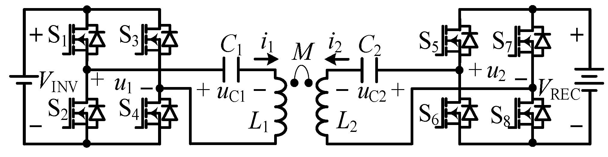
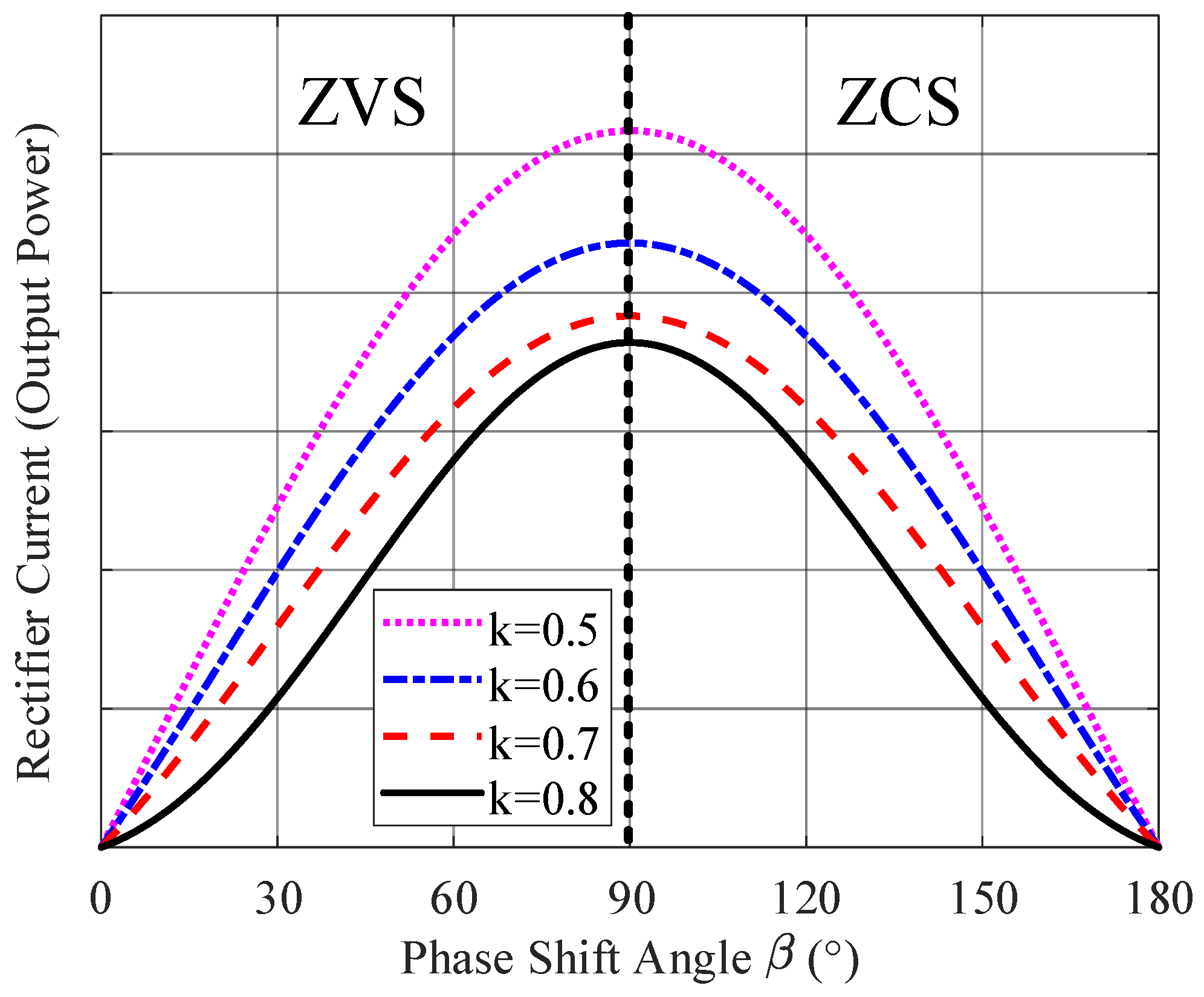
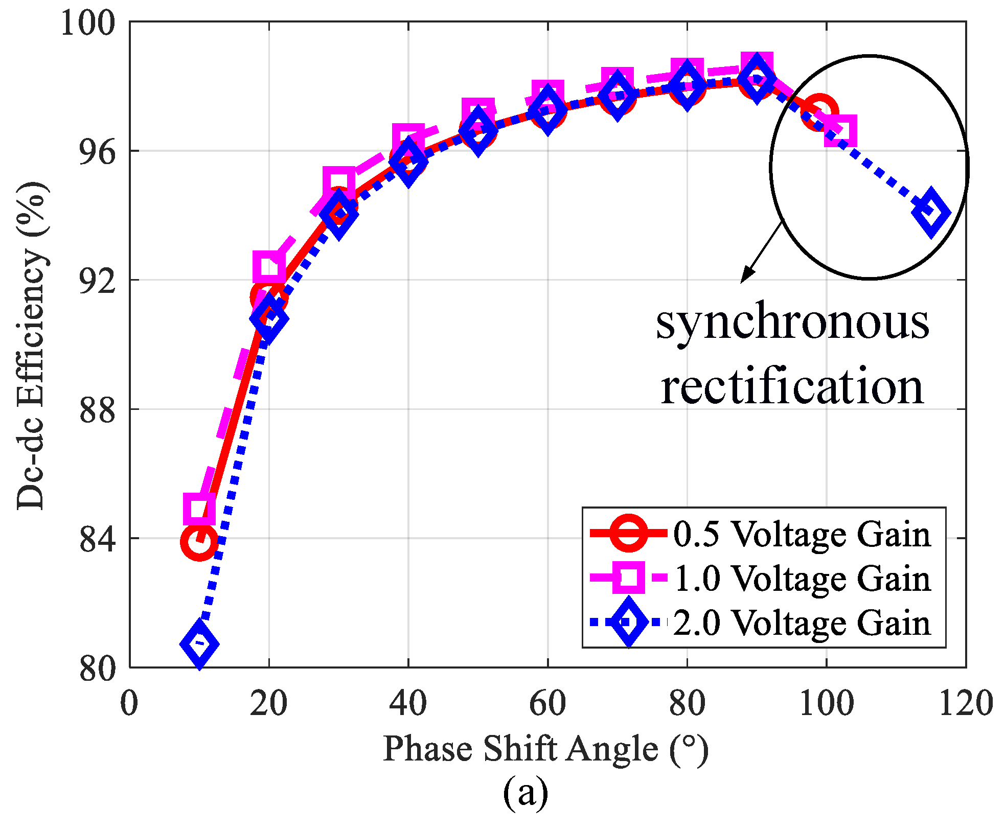
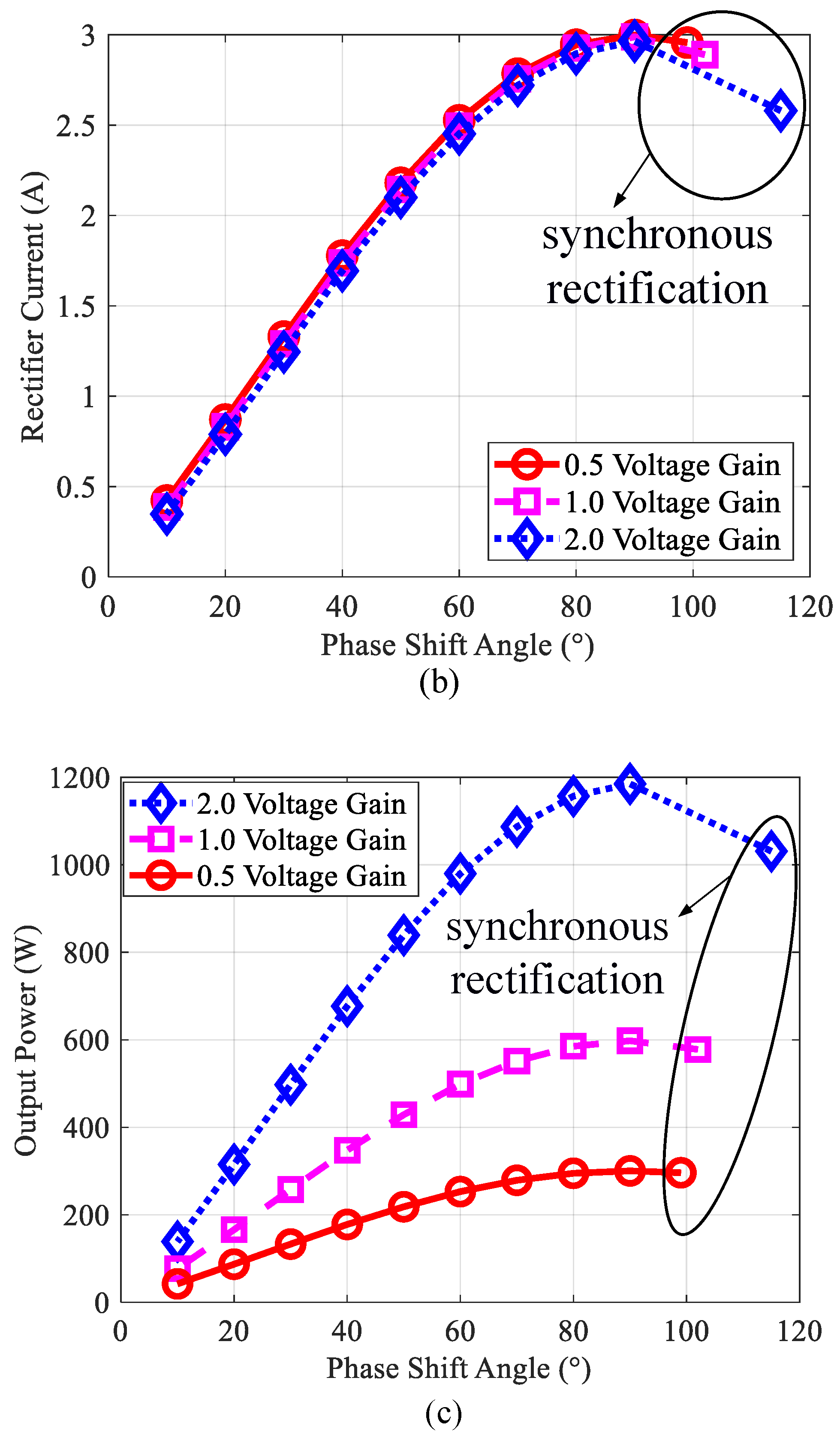
- Synchronous rectification is normally conducted to the secondary-side rectifier of the loosely coupled WPT systems to improve efficiency [9,10]. However, it is found in strongly coupled WPT systems that this will result in the primary-side inverter working in hard switching, leading to decreasing efficiency and potential circuit failures. Additionally, in loosely coupled WPT systems, dual-side phase-shift control is seldomly used to regulate the secondary-side charging current due to the fact that too much reactive power will be introduced if the phase difference between the primary-side and secondary-side voltages is not 90°. However, in strongly coupled WPT systems, since the coupling coefficient is large, the efficiency can still be high even though the phase difference is not 90°. Thus, the secondary-side charging current and even bidirectional power flow can be easily regulated. The contributions of this paper include building the mathematical model of dual-side phase-shift control for strongly coupled WPT systems;
- (2)
- Investigating the performance of dual-side phase-shift control for strongly coupled WPT systems;
- (3)
- Revealing that synchronous rectification is not suitable for strongly coupled WPT system because soft switching can be lost;
- (4)
- Experimentally validating the model and analysis.
This paper studies the dual-side phase-shift control of the strongly coupled series–series compensated WPT systems. The mathematical models based on first harmonic approximation (FHA) and differential equations are built in Section 2. Experimental results are offered in Section 3 to validate the analysis. Section 4 concludes this paper.
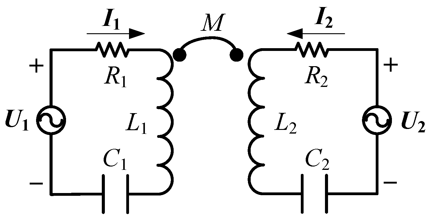
2. Mathematical Modelling
The topology of a series–series compensated EV wireless charging system with full-bridge converters is shown in Figure 1. S1–S8 are the active switches. VINV (VREC), u1 (u2), i1 (i2), L1 (L2), C1 (C2), uC1 (uC2) are the respective primary-side (secondary-side) dc voltage, ac voltage, ac current, self-inductance, capacitance, and capacitor voltage. M is the mutual inductance.
Figure 1.
Topology of a series–series compensated WPT system for EV charging.
The load is modelled as a voltage-source load. The voltage gain of the WPT system GV is defined as
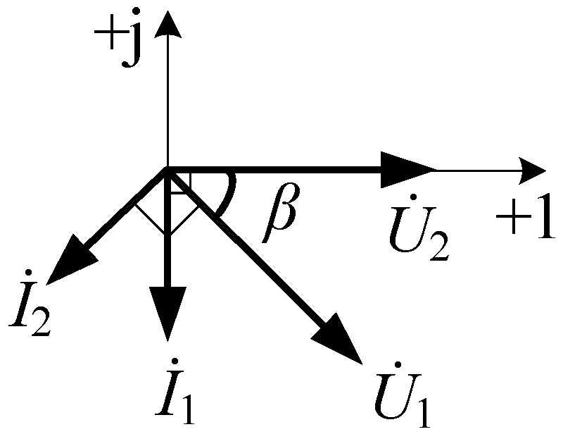
2.1. First Harmonic Approximation
FHA is normally utilized to model the WPT system. Based on FHA, the equivalent circuit is shown in Figure 2. U1 (U2) and I1 (I2) are the fundamental components of the inverter (rectifier) ac voltage and current, respectively. R1 and R2 are the equivalent resistance of the transmitter and receiver, respectively. With 180° phase shift within the legs of the inverter and the rectifier, we have
Figure 2.
Equivalent circuit of series–series compensated WPT system based on FHA.
The model in Figure 2 can be established as
where ω is the working angular frequency and the parameters in bold represent the phasor quantities.
At resonance where
and ignoring R1 and R2 when their voltage drops are significantly smaller than U1 and U2, we have
According to FHA, the transmitter and receiver currents are constant.
With the dual-side phase-shift angle of β, by which U2 leads U1, the phasor diagram is plotted in Figure 3 [11]. The rectifier dc current and the output power can be calculated as
Figure 3.
Phasor diagram of series–series compensated WPT system based on FHA.
IREC and Pout change sinusoidally with the dual-side phase-shift angle β.
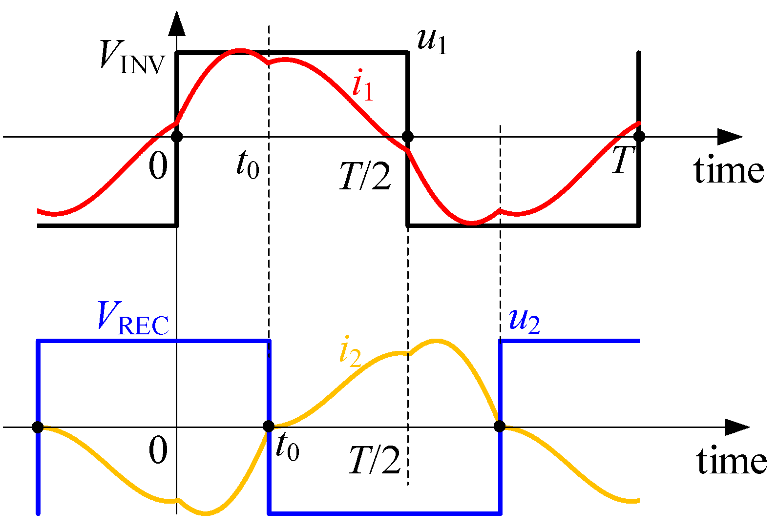
2.2. Time-Domain Modelling
The waveforms of the series–series compensated WPT system are distorted and can be discontinuous [10,12]. Therefore, FHA is no longer valid. Similar to [12], the time domain modelling based on differential equations is conducted. The typical waveforms are shown in Figure 4. Assume that the cycle is T. At t = 0, u1 is rising, and at t0, u2 is falling. In the first half cycle, S1 and S4 are on and S2 and S3 are off. In the second half cycle, S1 and S4 are off and S2 and S3 are on. Due to symmetry, only the first half cycle is considered.
Figure 4.
Typical waveforms of inverter and rectifier ac voltages and currents.
When 0 < t < t0, S1, S4, S5, and S8 are all on, namely u1 and u2 are both positive, the differential equations can be given as
where the subscript “−1” denotes that the symbols are in the interval of 0 < t < t0.
When t0 < t < T/2, S2, S3, S5, and S8 are all on, namely u1 is positive and u2 is negative, the differential equations can be given as
where the subscript “−2” denotes that the symbols are in the interval of t0 < t < T/2.
With considerations of the boundary conditions, namely
the differential equations can be solved.
The rectifier dc current and the output power can be calculated as
where k is the coupling coefficient, defined as
t0 indicates the phase-shift instant when the secondary-side rectifier is switching. The relationship between t0 and β is
Thus, (11) and (12) are transformed into
For synchronous rectification, there should be one more boundary condition as i2-1(t0) = i2-2(t0) = 0, which is the natural zero crossing point of the receiver current. By solving this, the phase-shift angle between u2 and the u1 is larger than 90°. In this condition, i1-1(0) is larger than 0, indicating that soft switching is lost.
2.3. Comparison of FHA and Model Based on Differential Equations
Dividing (15) by (6) yields the ratio of the rectifier dc current from the differential equations over that from FHA, namely
The ratio of the rectifier dc currents in (17), varying with the phase difference between u2 and u1, namely β, is plotted in Figure 5. At strong couplings, the rectifier dc currents are larger than the predictions from FHA between the phase-shift angles of 60° and 120°, and smaller at other phase-shift angles. This shows the inaccuracy of FHA at strong couplings.
Figure 5.
Ratio of IREC in (17) varying with β.
In Figure 2 and Figure 3, the corresponding voltage and current (U1 and I1, U2 and I2) are defined in an associate reference direction. This means that when the active power of the voltage source is positive, the voltage source acts as an actual source and the active power is transferred from the voltage source to the outside circuit; when the active power of the voltage source is negative, the voltage source acts as a sink and the active power is transferred from the outside circuit to the voltage source. Thus, in Figure 3, when U2 leads U1 or β ∈ (0, 180°), active power is transferred from the primary side to the secondary side; when U2 lags behind U1 or β ∈ (−180°, 0), active power is transferred from the secondary side to the primary side. This is also true for strongly coupled cases.
Attention should be paid to the range of [0, 180°] where active power is transferred from the primary side to the secondary side. As can also be seen from Figure 3, when 0 < β < 90°, I1 lags behind U1, which means the input impedance is inductive. Thus, zero voltage switching (ZVS) can be achieved for both the primary-side inverter and secondary-side rectifier. When 90° < β < 180°, I1 leads U1, and zero current switching (ZCS) can be achieved for both the primary-side inverter and secondary-side rectifier. When MOSFETs are used, ZVS is preferred, indicating that the dual-side phase-shift angle should be in the range of [0, 90°]. The variations of the rectifier currents or output power with the dual-side phase-shift angle β are plotted in Figure 6.
Figure 6.
Variation of IREC or Pout with β.
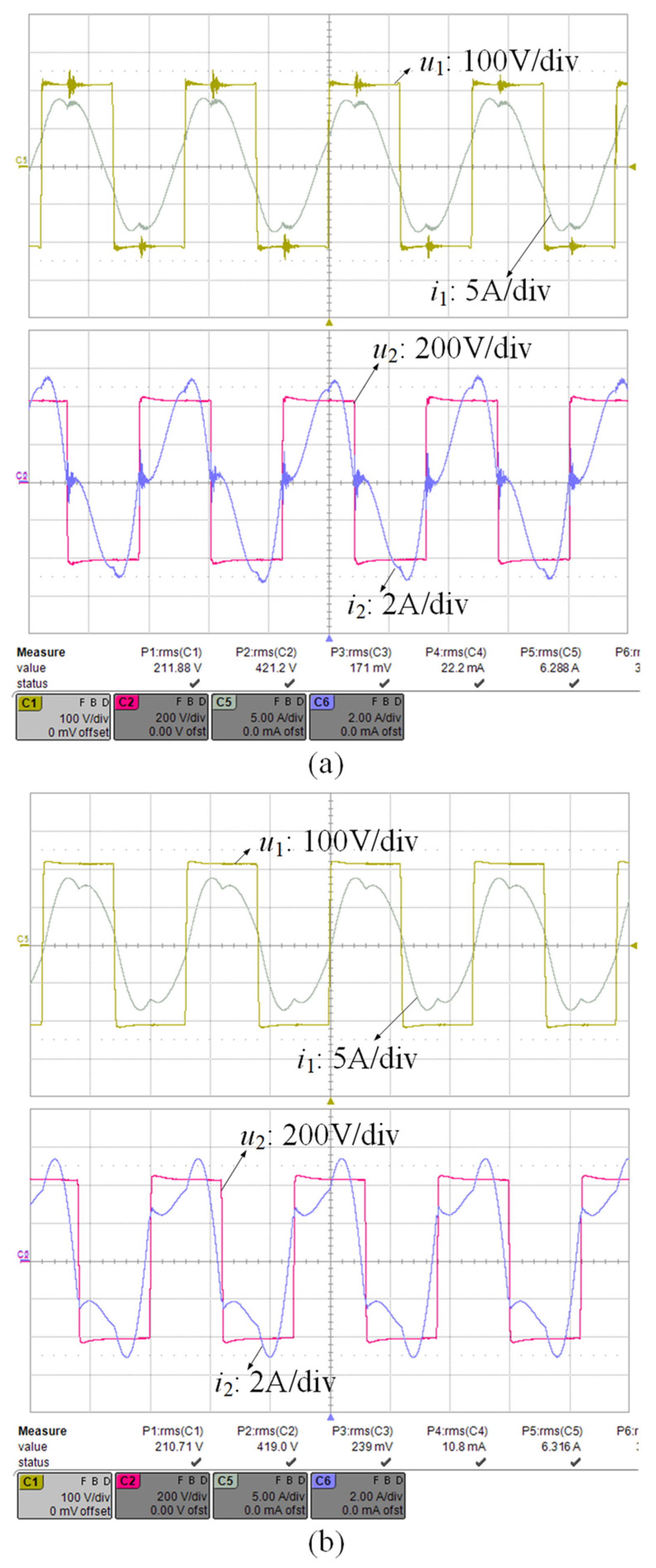
3. Experimental Validation
An experimental prototype is implemented to validate the analysis, as shown in Figure 7. The parameters of the experimental prototype are tabulated in Table 1. The prototype with the coupling coefficient of 0.64 is a typical strongly coupled WPT system. VINV is set to 200 V. Three voltage gains are selected: 0.5, 1.0, and 2.0, with corresponding VREC of 100 V, 200 V, and 400 V.
Figure 7.
Photo of the experimental prototype.
Table 1.
Parameters of experimental prototype.
The measured dc-dc efficiency, the rectifier current, and the output power under synchronous rectification and phase shift are illustrated in Figure 8. The data denoted as “synchronous rectification” indicate that synchronous rectification is achieved at these phase-shift angles, which are larger than 90° and locate at the range of ZCS, as shown in Figure 6. Thus, with synchronous rectification, soft switching is lost. By changing the phase shift angle between 0 and 90°, the output current, namely the rectifier current, can be easily regulated, as shown in Figure 8b. In the wide regulation range, the dc-dc efficiency can still be high, different from the loosely coupled wireless power transfer systems.

Figure 8.
(a) Measured dc-dc efficiency, (b) rectifier current, and (c) output power under three voltage gains.
The experimental waveforms when the voltage gain is 2.0 are shown in Figure 9. With synchronous rectification in strongly coupled WPT systems, the phase-shift angles are always larger than 90°, and the dc-dc efficiency is smaller than that with a 90° phase shift. The inverter may work in hard switching, as shown in Figure 9a. With a 90° phase shift, this issue is solved, as shown in Figure 9b.
Figure 9.
Experimental waveforms with 2.0 voltage gain: (a) synchronous rectification; (b) 90° phase shift.
4. Conclusions
This paper presented the modelling and dual-side phase-shift control of the strongly coupled series–series compensated WPT systems. There are issues with synchronous rectification in strongly coupled series–series compensated WPT systems: the efficiency is not the highest and the inverter may work in hard switching. In comparison, with a 90° phase shift, the inverter will always work in soft switching and the efficiency is the highest. Moreover, with dual-side phase-shift regulation in strongly coupled series–series compensated WPT systems, the output current can be easily regulated by changing the phase difference between the primary-side and the secondary-side converters with relatively high dc-dc efficiency over a wide regulation range, which is a different characteristic from the loosely coupled WPT systems.
Author Contributions
Conceptualization, Y.Z., Z.S., Y.W., H.W. and W.P.; methodology, Y.Z., Z.S., Y.W., H.W. and W.P.; software, Y.Z., Z.S., Y.W., H.W. and W.P.; validation, Y.Z., Z.S., Y.W., H.W. and W.P.; formal analysis, Y.Z., Z.S., Y.W., H.W. and W.P.; investigation, Y.Z., Z.S., Y.W., H.W. and W.P.; resources, Y.Z., Z.S., Y.W., H.W. and W.P.; data curation, Y.Z., Z.S., Y.W., H.W. and W.P.; writing—original draft preparation, Y.Z.; writing—review and editing, Y.Z., Z.S., Y.W., H.W. and W.P.; visualization, Y.Z., Z.S., Y.W., H.W. and W.P.; supervision, Y.Z., Z.S., Y.W., H.W. and W.P.; project administration, Y.Z.; funding acquisition, Y.Z. All authors have read and agreed to the published version of the manuscript.
Funding
This research was funded in part by the National Natural Science Foundation of China (grant number 52107183) and in part by the State Key Laboratory of Power System and Generation Equipment (grant number SKLD21KZ05).
Conflicts of Interest
The authors declare no conflict of interest.
References
- Ye, F.; Chen, Q.; Chen, W. Analysis and design of magnetic coupling structure in wireless power transmission system. In Proceedings of the 2016 Asia-Pacific International Symposium on Electromagnetic Compatibility (APEMC), Shenzhen, China, 17–21 May 2016; pp. 679–682. [Google Scholar]
- Huynh, P.S.; Williamson, S.S. Analysis and design of soft-switching active-clamping half-bridge boost inverter for inductive wireless charging applications. IEEE Trans. Transport. Electr. 2019, 5, 1027–1039. [Google Scholar] [CrossRef]
- Dai, X.; Wu, J.; Jiang, J.; Gao, R.; Madawala, U.K. An energy injection method to improve power transfer capability of bidirectional WPT system with multiple pickups. IEEE Trans. Power Electron. 2021, 36, 5095–5107. [Google Scholar] [CrossRef]
- Li, Y.; Dong, W.; Yang, Q.; Zhao, J.; Liu, L.; Feng, S. An automatic impedance matching method based on the Feedforward-Backpropagation neural network for WPT system. IEEE Trans. Ind. Electron. 2019, 66, 3963–3972. [Google Scholar] [CrossRef]
- Yan, Z.; Zhang, Y.; Kan, T.; Lu, F.; Zhang, K.; Song, B.; Mi, C.C. Frequency optimization of a loosely coupled underwater wireless power transfer system considering eddy current loss. IEEE Trans. Ind. Electron. 2019, 66, 3468–3476. [Google Scholar] [CrossRef]
- Qu, X.; Yao, Y.; Wang, D.; Wong, S.; Tse, C.K. A family of hybrid IPT topologies with near Load-Independent output and high tolerance to pad misalignment. IEEE Trans. Power Electron. 2020, 35, 6867–6877. [Google Scholar] [CrossRef]
- Song, B.; Cui, S.; Li, Y.; Zhu, C. A fast and general method to calculate mutual inductance for EV dynamic wireless charging system. IEEE Trans. Power Electron. 2021, 36, 2696–2709. [Google Scholar] [CrossRef]
- Zhang, Y.; Yan, Z.; Kan, T.; Liu, Y.; Mi, C.C. Modelling and analysis of the distortion of strongly-coupled wireless power transfer systems with SS and LCC–LCC compensations. IET Power Electron. 2019, 12, 1321–1328. [Google Scholar] [CrossRef] [Green Version]
- Song, J.; Liu, M.; Kang, N.; Ma, C. A universal optimal drain–source voltage tracking scheme for synchronous resonant rectifiers in megahertz wireless power transfer applications. IEEE Trans. Power Electron. 2021, 36, 5147–5156. [Google Scholar] [CrossRef]
- Lee, E.S.; Kim, M.Y.; Lee, S.G.; Lee, B.S. A high-efficient duty-controlled synchronous rectifier for uniformly powering of multiple receivers. In Proceedings of the 2020 IEEE PELS Workshop on Emerging Technologies: Wireless Power Transfer (WoW), Seoul, Korea, 15–19 November 2020; pp. 334–340. [Google Scholar]
- Zhang, Y.; He, F.; Liu, F.; Chen, K.; Zhao, Z. Comparison of two bidirectional wireless power transfer control methods. In Proceedings of the 2016 Asia-Pacific International Symposium on Electromagnetic Compatibility (APEMC), Shenzhen, China, 17–21 May 2016; pp. 68–70. [Google Scholar]
- Zhang, Y.; Li, X.; Chen, S.; Tang, Y. Soft switching for strongly coupled wireless power transfer system with 90° dual-side phase shift. IEEE Trans. Ind. Electron. 2021, in press. [Google Scholar] [CrossRef]
Publisher’s Note: MDPI stays neutral with regard to jurisdictional claims in published maps and institutional affiliations. |
© 2021 by the authors. Licensee MDPI, Basel, Switzerland. This article is an open access article distributed under the terms and conditions of the Creative Commons Attribution (CC BY) license (https://creativecommons.org/licenses/by/4.0/).