
A New On-board Charging-Driving Integrated Topology for V2G Technology

Abstract
:1. Introduction
1.1. Background
1.2. Current State of Integrated Topology
1.3. Research Contents
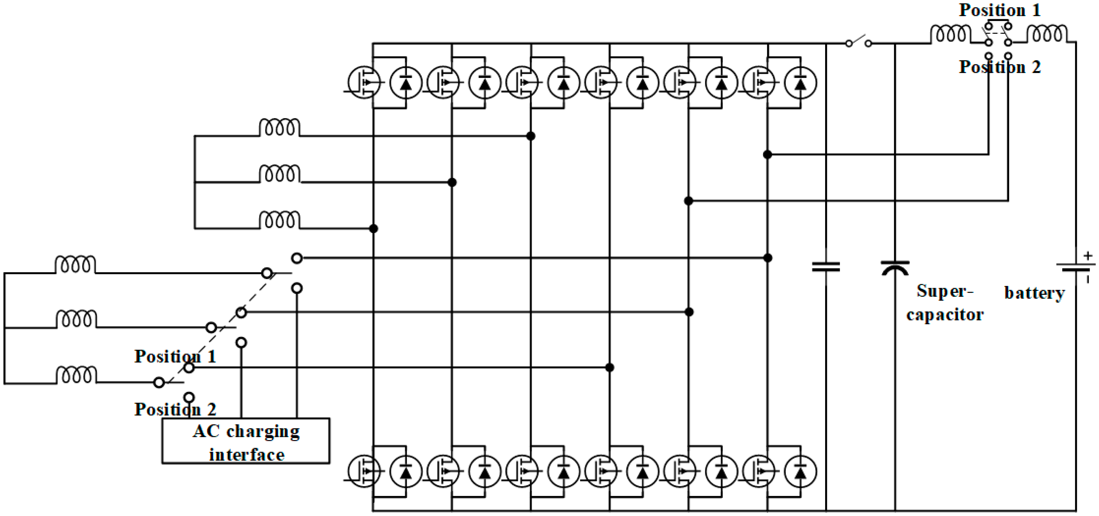
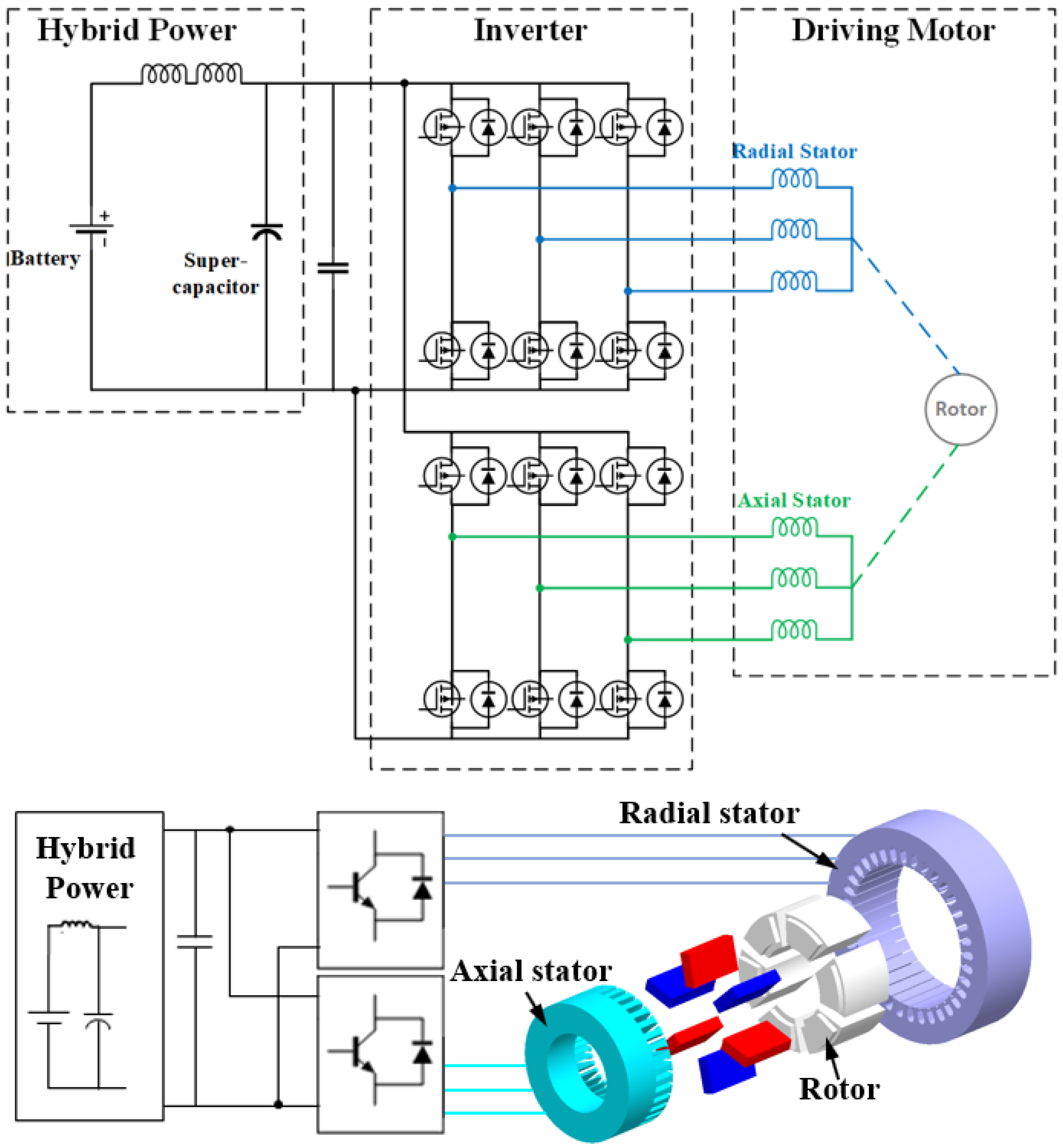
2. Power Circuit
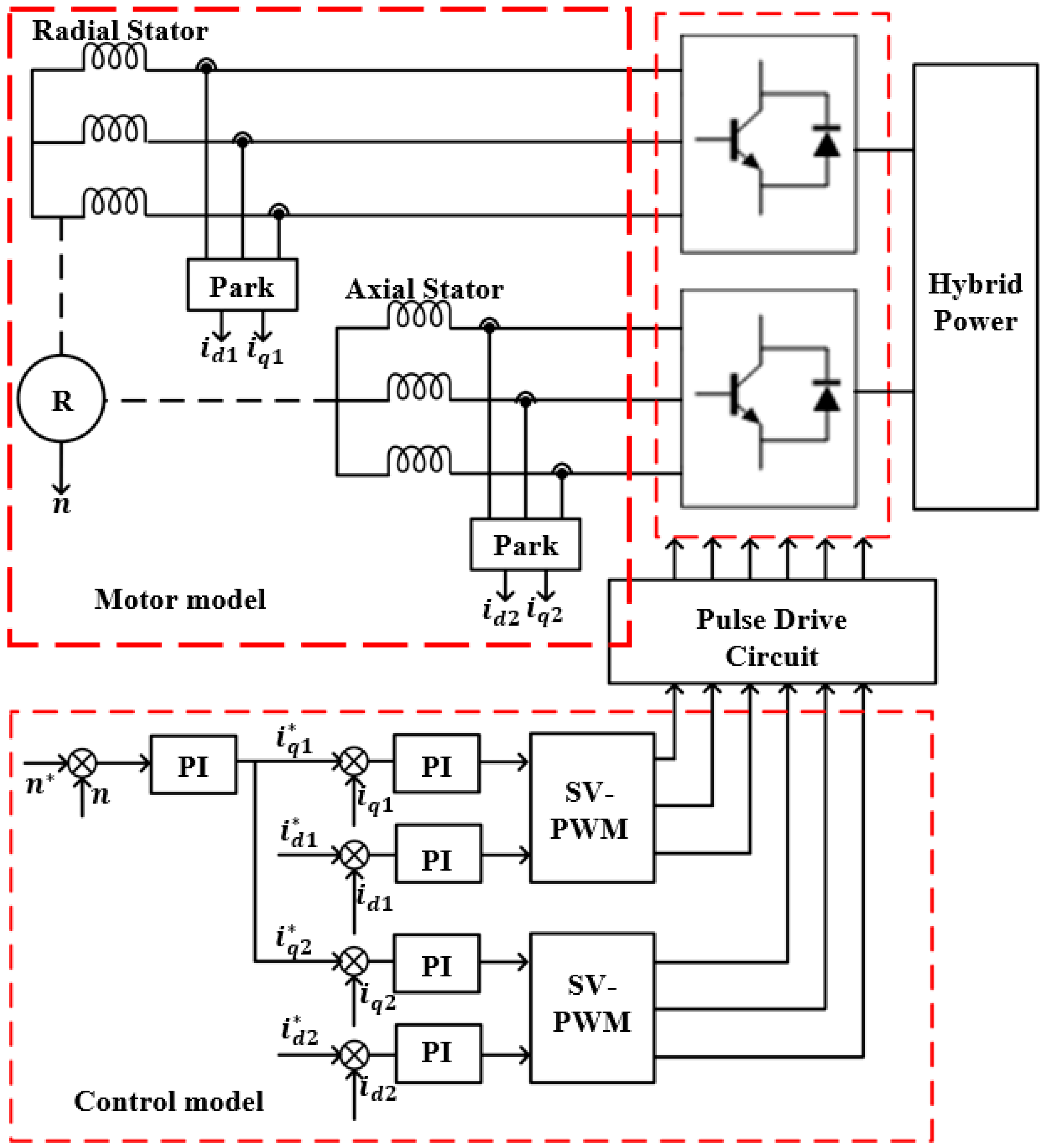
2.1. Driving Mode
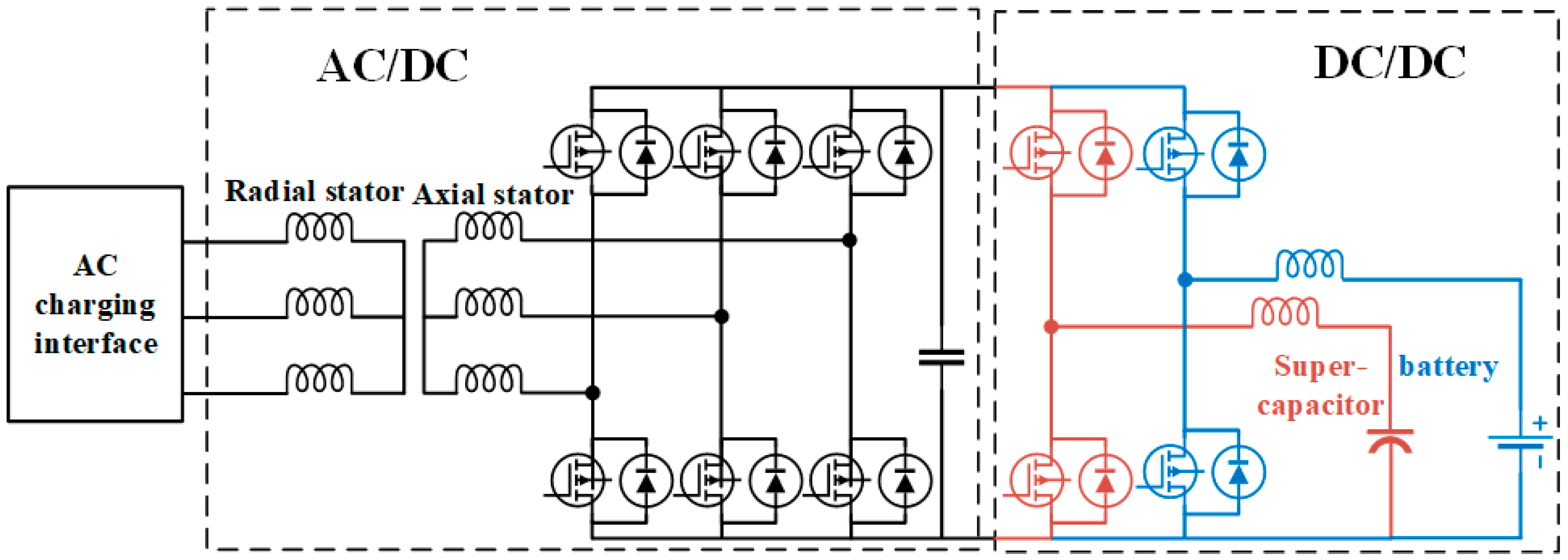
2.2. Charging Mode
2.3. V2G Functions
3. Results and Discussion
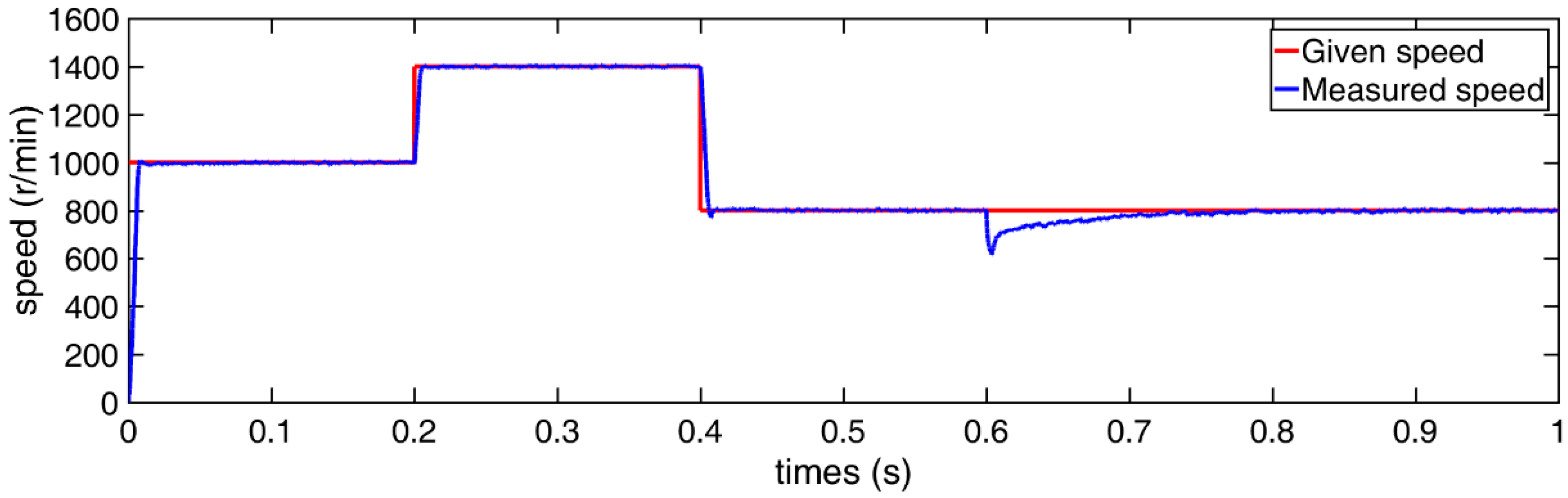
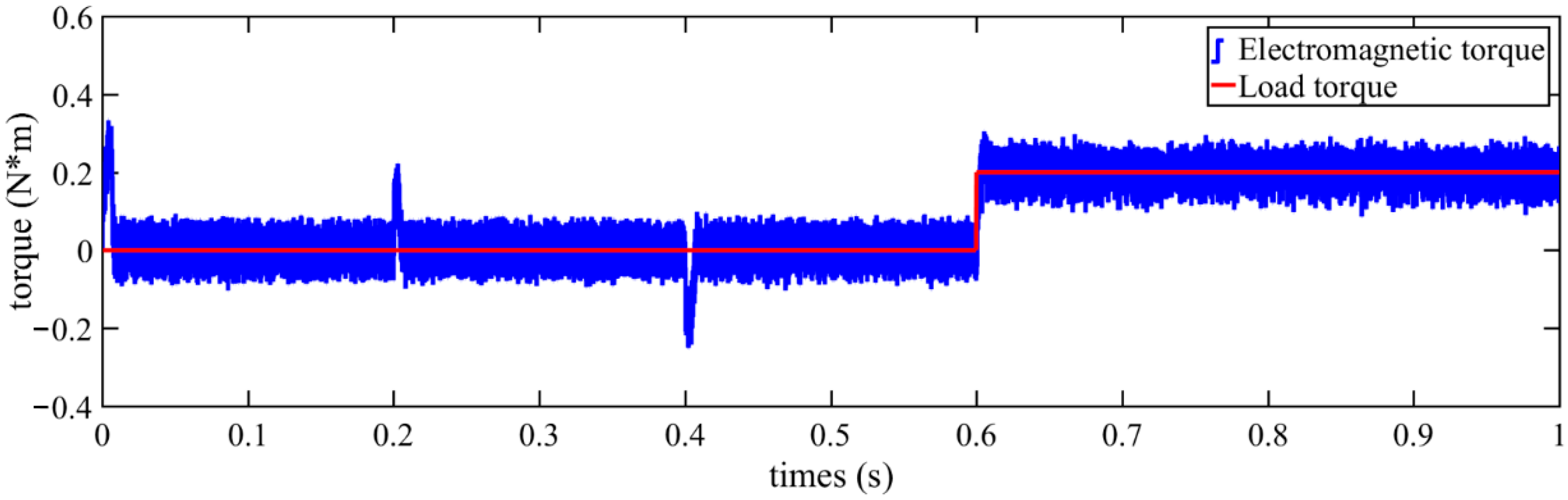
3.1. Driving Mode
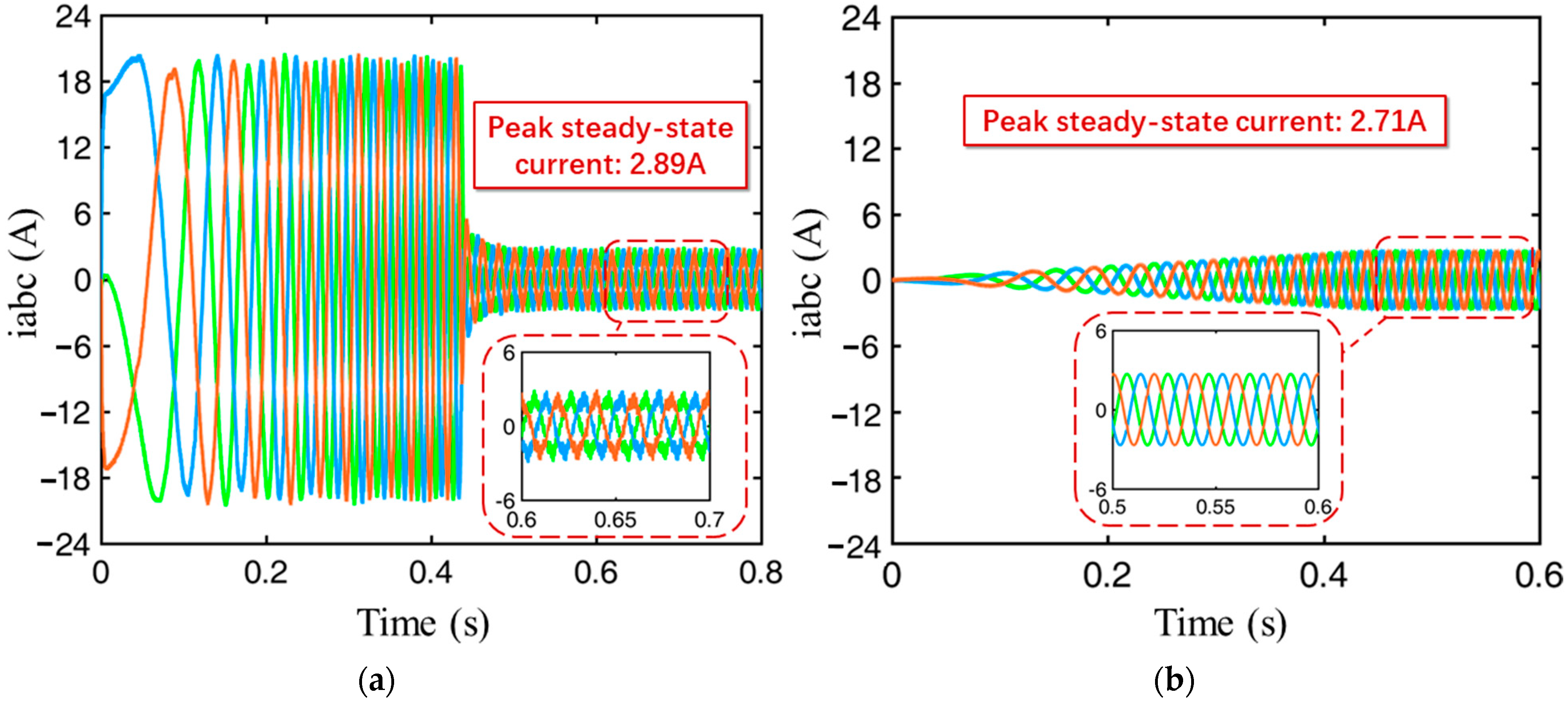
3.2. Charging Mode
4. Conclusions
5. Future Research Directions
- Design the control strategy to make the battery and the supercapacitor work together and complete different V2G functions;
- Design the corresponding regenerative energy braking strategy according to the characteristics of the topology structure, improve driving range and energy efficiency;
- Built the experimental platform to verify its performance, analyze vibration and noise of the topology operating in drive mode and charge mode.
Author Contributions
Funding
Institutional Review Board Statement
Informed Consent Statement
Data Availability Statement
Conflicts of Interest
References
- Shah, F.A.; Sheikh, S.S.; Mir, U.I.; Athar, S.O. Battery Health Monitoring for Commercialized Electric Vehicle Batteries: Lithium-Ion. In Proceedings of the 2019 International Conference on Power Generation Systems and Renewable Energy Technologies (PGSRET), Istanbul, Turkey, 26–27 August 2019; pp. 1–6. [Google Scholar]
- Linru, J.; Yuanxing, Z.; Taoyong, L.; Xiaohong, D.; Jing, Z. Analysis on Charging Safety and Optimization of Electric Vehicles. In Proceedings of the 2020 IEEE 6th International Conference on Computer and Communications (ICCC), Chengdu, China, 11–14 December 2020; pp. 2382–2385. [Google Scholar]
- Frieske, B.; Kloetzke, M.; Mauser, F. Trends in vehicle concept and key technology development for hybrid and battery electric vehicles. In Proceedings of the 2013 World Electric Vehicle Symposium and Exhibition (EVS27), Barcelona, Spain, 17–20 November 2013; pp. 1–12. [Google Scholar]
- Emilienne, L.; Zhang, J.; Rodrigue, D.N.S. Research on V2G Participating in Power System Frequency Control. In Proceedings of the 2019 IEEE 7th International Conference on Smart Energy Grid Engineering (SEGE), Oshawa, ON, Canada, 12–14 August 2019; pp. 230–234. [Google Scholar]
- Zhang, J.; Yan, H.; Ding, N.; Li, T.; Su, S.; Zhang, J. Electric Vehicle Charging Network Development Characteristics and Policy Suggestions. In Proceedings of the 2018 International Symposium on Computer, Consumer and Control (IS3C), Taichung, Taiwan, 6–8 December 2018; pp. 469–472. [Google Scholar]
- Güldorum, H.C.; Şengör, İ.; Erdinç, O. Charging Management System for Electric Vehicles considering Vehicle-to-Vehicle (V2V) Concept. In Proceedings of the 12th International Conference on Electrical and Electronics Engineering (ELECO), Bursa, Turkey, 26–28 November 2020; pp. 188–192. [Google Scholar] [CrossRef]
- Shakeel, F.M.; Malik, O.P. Vehicle-To-Grid Technology in a Micro-grid Using DC Fast Charging Architecture. In Proceedings of the 2019 IEEE Canadian Conference of Electrical and Computer Engineering (CCECE), Edmonton, Canada, 5–8 May 2019; pp. 1–4. [Google Scholar]
- Wang, T.; Wang, H.; Xu, B.; Sui, J. An integrated topology for battery charging and motor driving in electrical vehicle. In Proceedings of the 2017 IEEE Conference on Energy Internet and Energy System Integration (EI2), Beijing, China, 27–28 November 2017; pp. 1–5. [Google Scholar]
- Sul, S.-K.; Lee, S.-J. An integral battery charger for four-wheel drive electric vehicle. IEEE Trans. Ind. Appl. 1995, 31, 1096–1099. [Google Scholar] [CrossRef]
- Solero, L. Nonconventional on-board charger for electric vehicle propulsion batteries. IEEE Trans. Veh. Technol. 2001, 50, 144–149. [Google Scholar] [CrossRef]
- Pellegrino, G.; Armando, E.G.; Guglielmi, P. An Integral Battery Charger with Power Factor Correction for Electric Scooter. IEEE Trans. Power Electron. 2010, 25, 751–759. [Google Scholar] [CrossRef] [Green Version]
- Lacressonniere, F.; Cassoret, B. Converter used as a battery charger and a motor speed controller in an industrial truck. In Proceedings of the 2005 European Conference on Power Electronics and Applications, Dresden, Germany, 11–14 September 2005. [Google Scholar]
- Haghbin, S.; Khan, K.; Lundmark, S.; Alakula, M.; Carlson, O.; Leksell, M.; Wallmark, O. Integrated chargers for EV’s and PHEV’s: Examples and new solutions. In Proceedings of the The XIX International Conference on Electrical Machines—ICEM 2010, Rome, Italy, 6–8 September 2010; pp. 1–6. [Google Scholar]
- Wang, D.; Zhang, D.; Xue, D.; Peng, C.; Wang, X. A New Hybrid Excitation Permanent Magnet Machine with an Independent AC Excitation Port. IEEE Trans. Ind. Electron. 2019, 66, 5872–5882. [Google Scholar] [CrossRef]
- Yang, H. Analysis of supercapacitor charge redistribution through constant power experiments. In Proceedings of the 2017 IEEE Power & Energy Society General Meeting, Chicago, IL, USA, 16–20 July 2017; pp. 1–5. [Google Scholar] [CrossRef]
- Wang, D.; Shao, C.; Wang, X. Investigation of a novel hybrid radial and axial magnetic circuit permanent magnet motor with flux weakening capability for EVs. In Proceedings of the 2017 20th International Conference on Electrical Machines and Systems (ICEMS), Sydney, Australia, 11–14 August 2017; pp. 1–6. [Google Scholar] [CrossRef]
- Yilmaz, M.; Krein, P.T. Review of Battery Charger Topologies, Charging Power Levels, and Infrastructure for Plug-In Electric and Hybrid Vehicles. IEEE Trans. Power Electron. 2013, 28, 2151–2169. [Google Scholar] [CrossRef]
- Andreev, M.K. An Overview of Supercapacitors as New Power Sources in Hybrid Energy Storage Systems for Electric Vehicles. In Proceedings of the 2020 XI National Conference with International Participation (ELECTRONICA), Sofia, Bulgaria, 23–24 July 2020; pp. 1–4. [Google Scholar]
- Haghbin, S.; Lundmark, S.; Alakula, M.; Carlson, O. An Isolated High-Power Integrated Charger in Electrified-Vehicle Applications. IEEE Trans. Veh. Technol. 2011, 60, 4115–4126. [Google Scholar] [CrossRef]
- Bellache, K.; Camara, M.; Dakyo, B. Multi-physical characterization of supercapacitor. In Proceedings of the 2017 Twelfth International Conference on Ecological Vehicles and Renewable Energies (EVER), Monte Carlo, Monaco, 11–13 April 2017; pp. 1–5. [Google Scholar]


| Parameters | Unit | Supercapacitors | Lithium-Ion Batteries |
|---|---|---|---|
| Single Nominal Voltage | V | 2.7~2.85 | 3.7 |
| Working Temperature | °C | −20~+70 | −20~+60 |
| Charging Cycle Times | thousand times | 100~1000 | 0.5~10 |
| Electric Capacity | F | 100~12,000 | - |
| Specific Energy | mWh/g | 4~9 | 100~265 |
| Specific Power | W/g | 3~10 | 0.3~1.5 |
| Efficiency | % | 95 | 90 |
| Working life | years | 5~10 | 3~5 |
| Low Temperature Capacity Decay | %(−20 °C PS25 °C) | 30 | 3~5 |
| Energy Cost | RMB/kWh | 2500 | 10,000 |
| Power Cost | RMB/kW | 6000 | 650 |
| Parameters | J | R | |||||
|---|---|---|---|---|---|---|---|
| Unit | Kg × m2 | mH | mH | mH | mH | Ω | - |
| Value | 1.437 × 10⁻⁵ | −0.48 | −0.089 | 7.11 | 10.55 | 0.9 | 4 |
| Voltage A | Voltage B | Voltage C | Current A | Current B | Current C | Power | |
|---|---|---|---|---|---|---|---|
| Radial | 67.53 | 67.30 | 67.43 | 2.046 | 2.065 | 2.068 | 416.57 |
| Axial | 66.46 | 66.23 | 66.48 | 1.917 | 1.917 | 1.917 | 380.68 |
Publisher’s Note: MDPI stays neutral with regard to jurisdictional claims in published maps and institutional affiliations. |
© 2021 by the authors. Licensee MDPI, Basel, Switzerland. This article is an open access article distributed under the terms and conditions of the Creative Commons Attribution (CC BY) license (https://creativecommons.org/licenses/by/4.0/).
Share and Cite
Zhang, F.; Wang, D.; Peng, C.; Feng, Z.; Li, J.; Feng, W.; Li, Y.; Wang, X. A New On-board Charging-Driving Integrated Topology for V2G Technology. World Electr. Veh. J. 2021, 12, 231. https://doi.org/10.3390/wevj12040231
Zhang F, Wang D, Peng C, Feng Z, Li J, Feng W, Li Y, Wang X. A New On-board Charging-Driving Integrated Topology for V2G Technology. World Electric Vehicle Journal. 2021; 12(4):231. https://doi.org/10.3390/wevj12040231
Chicago/Turabian StyleZhang, Fangxu, Daohan Wang, Chen Peng, Zhenkang Feng, Junchen Li, Wentao Feng, Yang Li, and Xiuhe Wang. 2021. "A New On-board Charging-Driving Integrated Topology for V2G Technology" World Electric Vehicle Journal 12, no. 4: 231. https://doi.org/10.3390/wevj12040231
APA StyleZhang, F., Wang, D., Peng, C., Feng, Z., Li, J., Feng, W., Li, Y., & Wang, X. (2021). A New On-board Charging-Driving Integrated Topology for V2G Technology. World Electric Vehicle Journal, 12(4), 231. https://doi.org/10.3390/wevj12040231