1. Introduction
The ocean is a vast treasure house of resources, with infinite unknowns and possibilities, and the development of marine resources has important strategic significance for the future development of mankind [
1]. In recent years, Autonomous Underwater Vehicle (AUV) has developed rapidly and has undertaken important tasks such as underwater survey and intelligence collection. However, the energy carried by the AUV itself is limited and cannot meet the needs of long-term continuous work. Therefore, the establishment of underwater base stations and the use of Inductive Power Transfer (IPT) technology to supply power to AUVs can increase the underwater operating time of the aircraft, improve work efficiency, and enhance the concealment of AUVs. The biggest difference between the IPT system in the marine environment and the air is reflected in two aspects: One is that seawater has conductivity, which is a typical multiphysics coupling problem [
2]. The other is that the impact of ocean currents affects the stable transmission of electrical energy in the IPT system [
3,
4,
5,
6,
7,
8,
9].
After studying the influence of eddy current loss on the wireless charging system in seawater environment [
10], a multi-physical coupling model of IPT system in the marine environment is established. The fitting relationship between electromagnetic and environmental parameters is used to establish a multi-physical coupling model for IPT systems under the marine environment. The characteristics of electromagnetic fields, thermal fields, flow fields, and the coupling mechanism between them are studied. Through solving the calculation of the multi-physical coupling model [
11,
12], the field distribution of each physical field in the IPT system, and the distribution characteristics of its physical field parameters are given. This model lays the foundation for modeling, optimizing, and overall structural design of the following IPT systems.
2. IPT System
Wireless power transmission, also known as non-contact power transmission, refers to the conversion of electrical energy into other forms of relay energy (such as electromagnetic field energy, lasers, microwaves, and mechanical waves) through a transmitter. The relay energy is converted into electrical energy to realize wireless power transmission. Wireless power transmission technologies mainly include inductive wireless power transfer (Inductive Wireless Power Transfer, IPT), capacitive wireless power transmission (Capacitive Wireless Power Transfer, CPT), ultrasonic wireless power transmission (Ultrasonic Power Transfer, UPT).
Due to the late start of the research on UPT, the efficiency of the UPT system is usually less than 50%. In addition, the energy transmission distance of the UPT system is also very close, and the UPT system has a more complicated mechanical structure [
13]. Therefore, this article will conduct research on the basis of the IPT system.
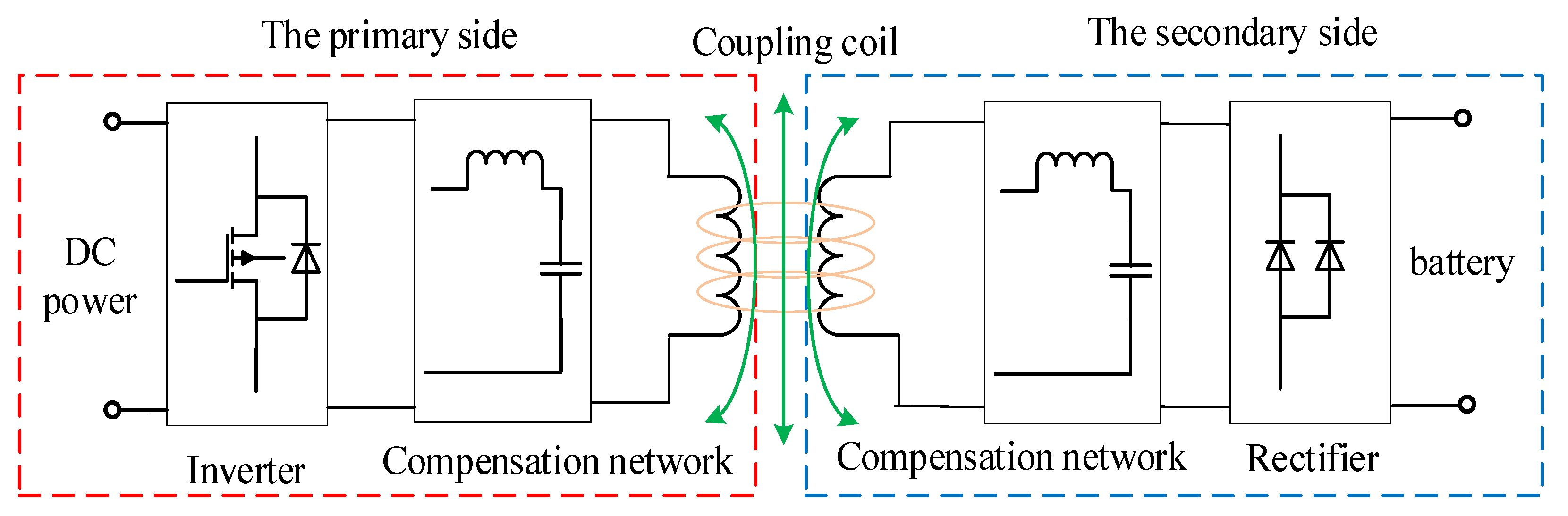
The underwater IPT system is shown in
Figure 1. The primary side circuit includes DC power supply, high-frequency inverter, compensation circuit, and coupling coil. The secondary side circuit includes coupling coil, compensation circuit, rectifier, and load. The DC power provided by the underwater base station or the mother ship is converted into AC power by a high-frequency inverter. The electric energy received by the secondary side is finally rectified to the DC load.
3. Multiphysics Coupling Model of IPT System
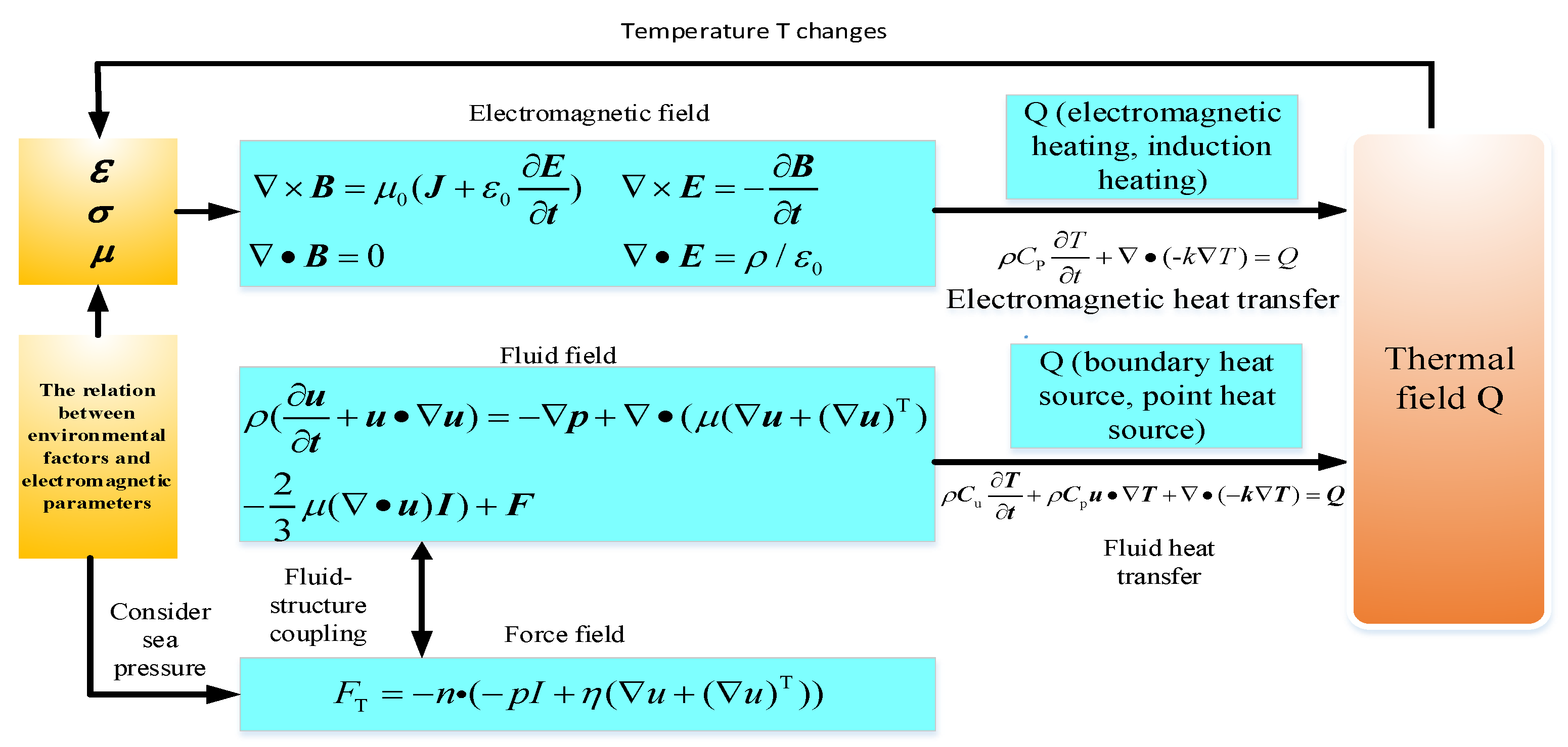
The marine environment IPT system is a multi-physical field coupling system with multi-factor interaction. The interaction relationship between various physical fields is shown in
Figure 2.
3.1. Electromagnetic Field
The electromagnetic field is mainly based on Maxwell’s equations:
Equation (1) is the Maxwell–Ampere law. The left side of the equation is the magnetic field curl. The two terms on the right represent the current density and the rate of electrical change.
Equation (2) is the Faraday’s law. The left side is the electric field curl, and the right side represents the rate of the electric field with time.
Equation (3) is the Gaussian magnetic law, which shows that the divergence of the magnetic field is zero everywhere.
Equation (4) is the Gaussian electric field law, which expresses that the electric field generated by the electric charge exists where the electric field divergence is not zero.
3.2. Fluid Field
In the marine IPT system, because seawater flows between the primary side and the secondary side coil, the system is affected by the fluid. Navier–Stokes equation can be used as Newton’s law of fluid motion. For compressible Newtonian fluid, the equation is as follows:
In Equation (5), μ is the hydrodynamic viscosity, u is the fluid velocity, p is the fluid pressure, and ρ is the fluid density, which is the hydrodynamic viscosity. The four fractions of this equation from left to right correspond to inertial force, pressure, viscous force, and external force acting on the fluid.
3.3. Electromagnetic Heating
Electromagnetic heating usually includes Joule heating, induction heating and microwave heating. The marine IPT system mainly includes Joule heating and induction heating, and the eddy current loss caused by the conductivity of seawater leads to waste of electric energy.
Heat conduction equation is as follows:
In Equation (6), ρ and CP represent the material density and volumetric heat capacity that change with temperature, k represents the thermal conductivity, and the heat source Q may be a constant value, such as Joule heating, induction heat and multiphysics, etc.
3.4. Fluid Heat Transfer
When studying the multi-field coupling of IPT in a marine environment, the seawater is designated as a non-isothermal flow with variable temperature. Three formulas are the heat transfer equation with convection term, the Stokes momentum conservation equation, and the mass conservation continuity equation to be used in the simulation of non-isothermal flow
The velocity field u of the fluid is used in the heat transfer equation, and the material properties in the fluid equation are related to temperature.
4. Simulation
The modeling parameters are shown in
Table 1:
As shown in
Figure 3 and
Figure 4.The entire packaging box is made of acrylic material, and the inside is also filled with acrylic material. There is no air gap between the coil and the outer layer of the packaging box. The conductivity of seawater is 4 S/m in the paper.
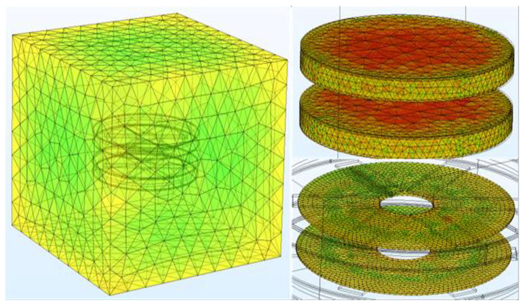
The size of coils, magnetic core, and aluminum plate can be specified during meshing. The refined free tetrahedral grid is used for division, while the sea area adopts the standard size. The results of the division are shown in
Figure 5:
The solution of multiple physical parameters based on finite element can be obtained by solving the model, and these results are saved in the data set.
5. Simulation Results
5.1. Magnetic Field Distribution
2A current is passed through the primary side of the coupling coil.
Figure 6 shows the magnetic field distribution in the yoz plane.
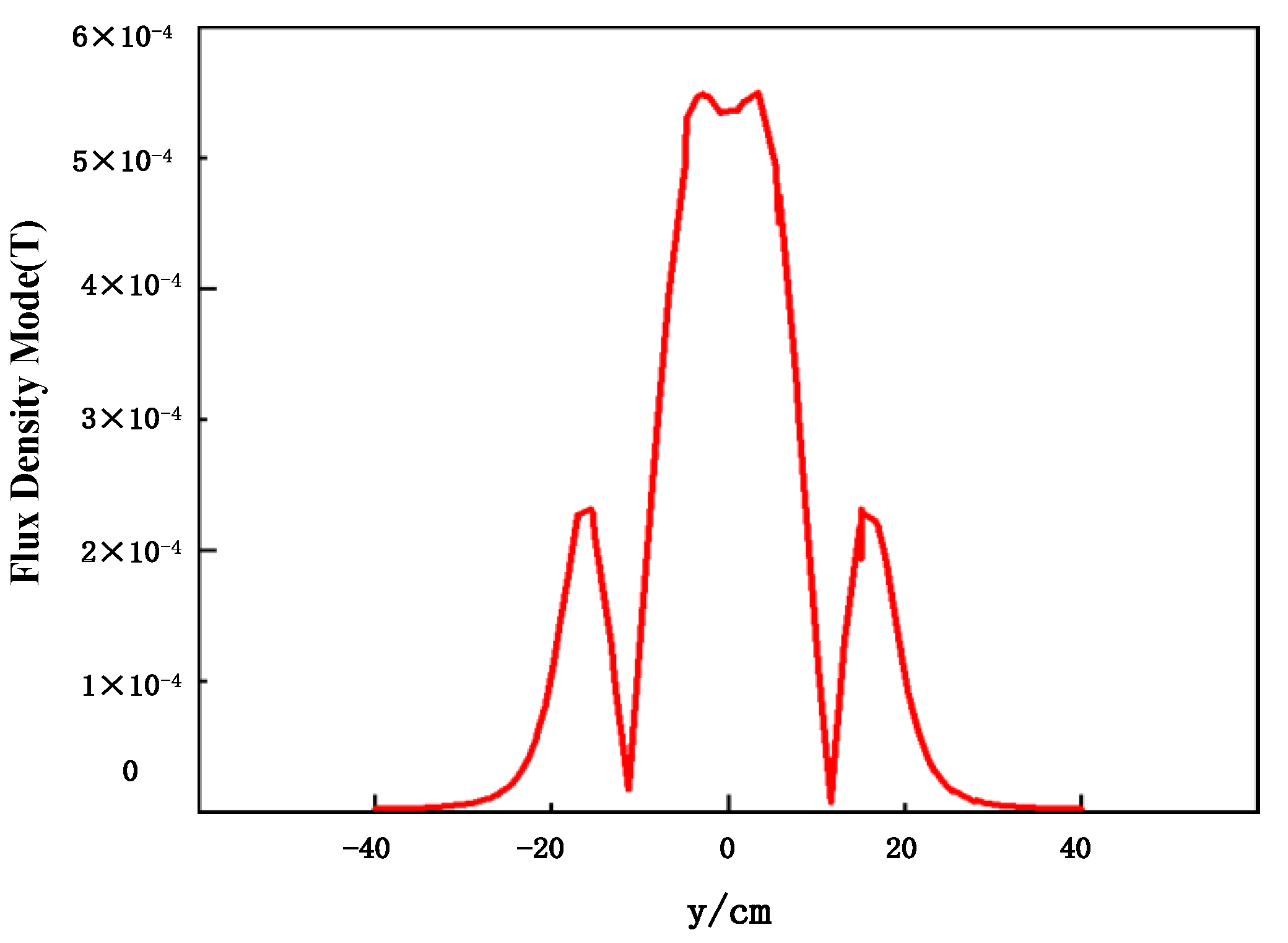
Take the center line of the coupling coil through the yoz plane, and the magnetic field distribution on the center line is shown in
Figure 7. It can be seen that the magnetic field intensity distribution law of the coil in the geometric range is: The strongest magnetic field appears at the center of two symmetrical radii. There is a symmetrical depression in the missing area of the inner loop of the coil and the boundary of the outer loop of the coil has a symmetrical peak. As it extends outward, the magnetic field gradually decreases.
5.2. Electric Field Distribution
Take the center line of the coupling coil at the same position. The electric field distribution on the yoz plane and the electric field distribution on the center line are shown in
Figure 8 and
Figure 9.
The electric field distribution law on the center line is as follows: The electric field at the center of the coil is almost zero, and electric field intensity reaches the maximum at the center of the coil radius, then the electric field gradually decreases to zero as it extends outward.
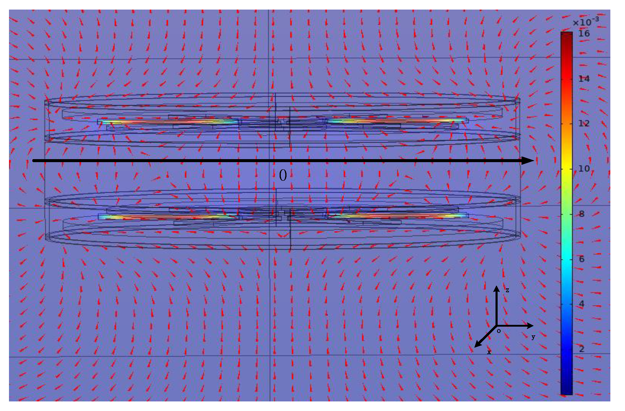
5.3. Flow Field Distribution
The speed of seawater flow is 5 m/s in the laminar flow interface, and the inlet pressure is set to two times the standard atmospheric pressure in the heat transfer module. The laminar flow direction and velocity distribution are shown in
Figure 10. When the seawater passes through the coupling mechanism, the flow direction will change significantly.
5.4. Electromagnetic Heating and Fluid Heat Transfer
In this subsection, the seawater temperature is set to 15 °C. When in a changing magnetic field, eddy currents are generated inside the seawater conductor. The eddy current flowing inside the seawater will cause loss and the conductor (seawater) to heat up. The heating effect in a small space will also cause the local temperature of the sea to rise, thereby affecting the physical parameters of seawater. The coil will generate Joule heat due to the passing of the current. Without considering the flow of seawater, the heat due to eddy current loss and the heat conduction of the coil heating will cause local seawater to heat up. As shown in
Figure 11, the seawater has a temperature rise of about 1 °C.
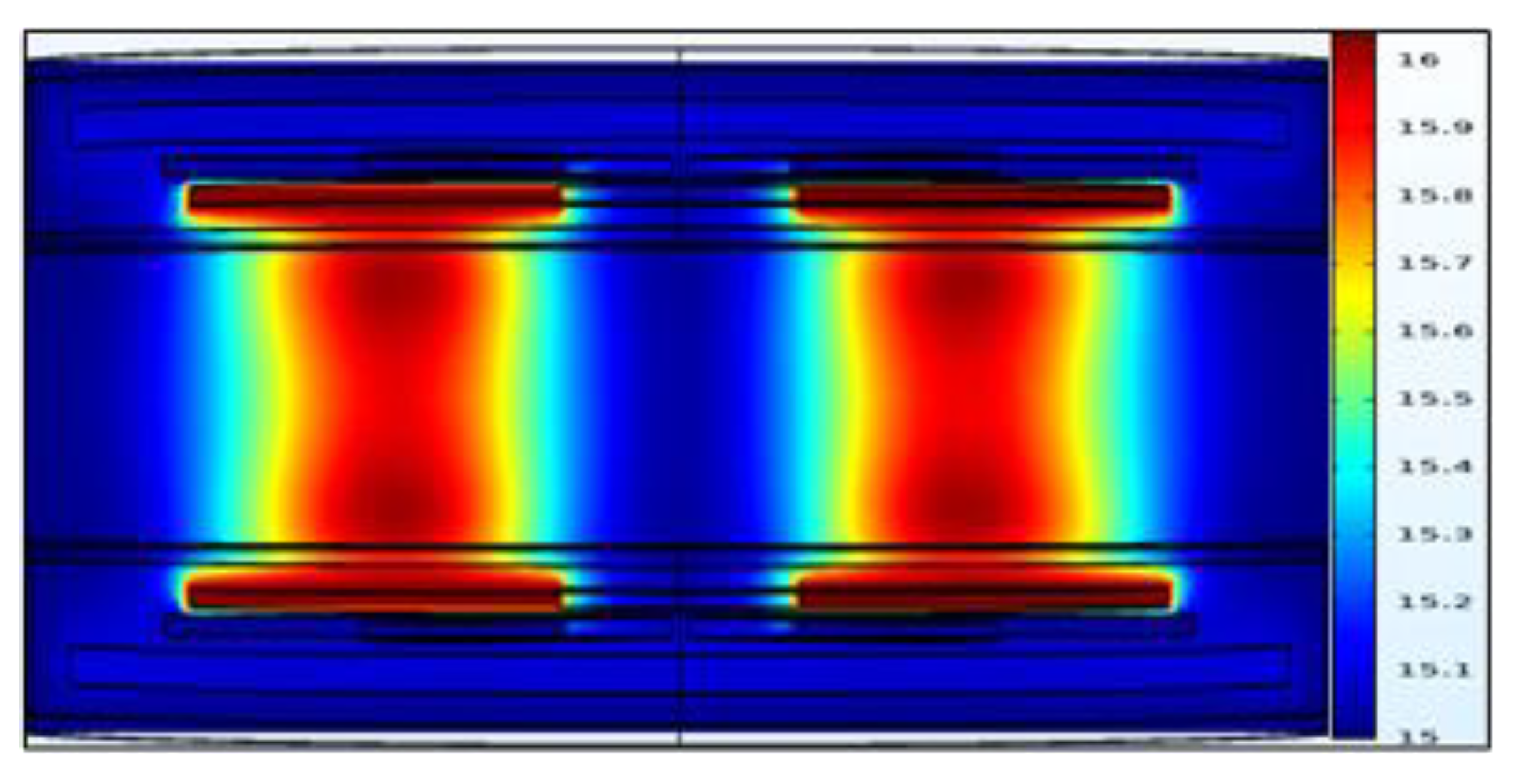
After considering the heat transfer of the fluid, the simulation results are shown in
Figure 12. It can be seen from the figure that the heat generated by the eddy current loss is exhausted in the flow of seawater, the temperature change between the coupling coils is small, and the temperature of the coupling coil is basically the setting seawater temperature.
After solving the established multiphysics model, the distribution of various parameters and physical fields of the ocean IPT system can be gotten, which is the basis of establishing a system mathematical model and studying its influence on efficiency in the our next research. The 3D model in the IPT marine environment occupies a very large storage space, and the solution requires high computer configuration.
By post-processing the data set, the multiphysics model of the IPT system can well display the distribution of electrical, magnetic, thermal, current, and fluid.
5.5. Finite Element Method
In the seawater environment, when the frequency
f > 100 kHz, severe eddy current loss will occur, resulting in a decrease in transmission efficiency [
11]. We will use the finite element method to calculate this part of the loss.
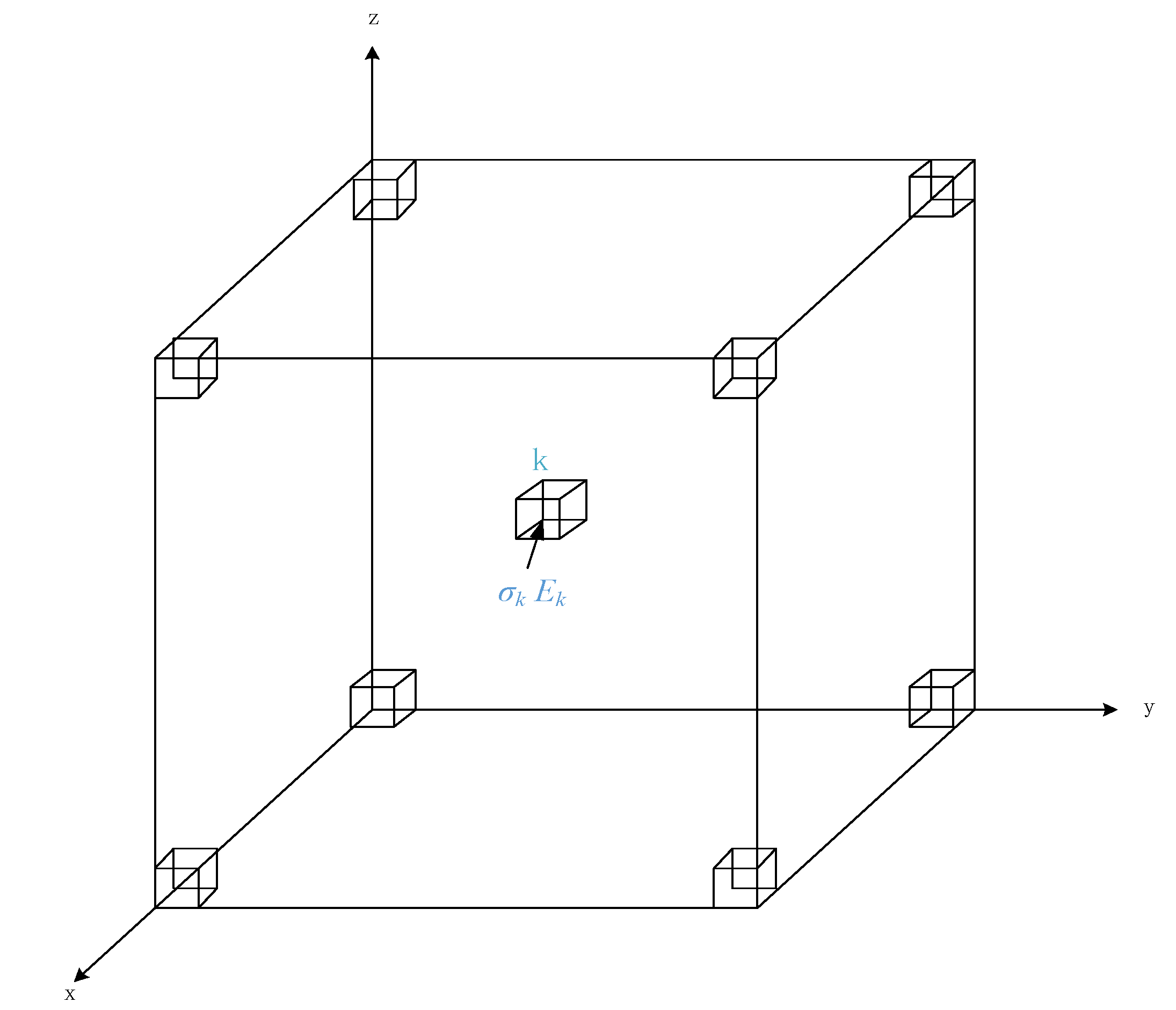
The electromagnetic field of the underwater wireless power transmission system is a vector field, and the electric and magnetic fields in space are the vector superposition of the electric and magnetic fields generated by the primary and secondary coils. The calculation area is discretized into M cube units, each cube unit has the same electromagnetic parameters, and the finite element method is used to calculate the spatial electromagnetic field [
10]. As shown in
Figure 13, in the solution range of the eddy current loss, the eddy current loss can be expressed as the superposition of the eddy current loss in the M small regular hexahedron domain. The conductivity σ and the electric field of the small regular hexahedron are expressed as
σk and
Ek, respectively, then the eddy current loss in the solution domain Eddy current loss can be expressed as:
6. Conclusions
Aiming at the problem of low efficiency and large loss of underwater inductive infinite power transmission system (IPT system), this paper conducts multiphysics simulation on the coupler part of the system. By analyzing the coupling mechanism of the physical fields in multiple underwater environments, the distribution modes and parameter characteristics of multiple physical fields are obtained, which provides a reference for the modeling and structural design of the underwater induction wireless power transmission system (IPT system).
Author Contributions
Software, Y.A.; supervision, K.Z.; writing—original draft, Y.A.; writing—review & editing, K.Z. All authors have read and agreed to the published version of the manuscript.
Funding
This research was funded by THE NATIONAL NATURAL SCIENCE FOUNDATION OF CHINA, grant number 52171338.
Conflicts of Interest
The authors declare no conflict of interest.
References
- Curtin, T.; Bellingham, J.; Catopovic, J.; Webb, D. Autonomous Oceanographic Sampling Networks. Oceanography 1993, 6, 86–94. [Google Scholar] [CrossRef] [Green Version]
- Duarte, C.; Gonçalves, F.; Silva, M.; Correia, V.; Pessoa, L.M. Experimental Evaluation of Coupling Coils for Underwater Wireless Power Transfer. In Proceedings of the 2019 IEEE Wireless Power Transfer Conference (WPTC), London, UK, 18–21 June 2019; IEEE: Piscataway, NJ, USA, 2019; pp. 557–560. [Google Scholar]
- Bradley, A.M.; Feezor, M.D.; Singh, H.; Sorrell, F.Y. Power systems for autonomous underwater vehicles. IEEE J. Ocean. Eng. 2001, 26, 526–538. [Google Scholar] [CrossRef]
- McEwen, R.S.; Hobson, B.W.; McBride, L.; Bellingham, J.G. Docking control system for a 54-cm-diameter (21-in) AUV. IEEE J. Ocean. Eng. 2008, 33, 550–562. [Google Scholar] [CrossRef]
- Kojiya, T.; Sato, F.; Matsuki, H.; Sato, T. Automatic power supply system to underwater vehicles utilizing non-contacting technology. IEEE 2004, 4, 2341–2345. [Google Scholar]
- Yoshida, S.; Tanomura, M.; Hama, Y.; Hirose, T.; Suzuki, A.; Matsui, Y.; Sogo, N.; Sato, R. Underwater wireless power transfer for non-fixed unmanned underwater vehicle in the ocean. Auton. Underw. Veh. 2016, 5, 177–180. [Google Scholar]
- Thrimawithana, D.J.; Madawala, U.K. A Generalized Steady-State Model for Bidirectional IPT Systems. IEEE Trans. Power Electron. 2013, 28, 4681–4689. [Google Scholar] [CrossRef]
- Hasaba, R.; Okamoto, K.; Kawata, S.; Eguchi, K.; Koyanagi, Y. Magnetic Resonance Wireless Power Transfer Over 10 m with Multiple Coils Immersed in Seawater. IEEE Trans. Microw. Theory Tech. 2019, 67, 4505–4513. [Google Scholar] [CrossRef]
- Bana, V.; Kerber, M.; Anderson, G.; Rockway, J.D.; Phipps, A. Underwater wireless power transfer for maritime applications. In Proceedings of the 2015 IEEE Wireless Power Transfer Conference (WPTC), Boulder, CO, USA, 13–15 May 2015; IEEE: Piscataway, NJ, USA, 2015; pp. 1–4. [Google Scholar]
- Zhang, K.; Ma, Y.; Yan, Z.; Di, Z.; Song, B.; Hu, A.P. Eddy Current Loss and Detuning Effect of Seawater on Wireless Power Transfer. IEEE J. Emerg. Sel. Top. Power Electron. 2020, 8, 909–917. [Google Scholar] [CrossRef]
- Liu, X.; Zhu, J.; Yu, Z.; Luo, J.; Wu, D. Optimization Design of Wireless Charging Magnetic Coupling Coil Based on Finite Element. In Proceedings of the 2019 IEEE 3rd International Conference on Circuits, Systems and Devices (ICCSD), Chengdu, China, 23–25 August 2019; IEEE: Piscataway, NJ, USA, 2019; pp. 59–64. [Google Scholar]
- Zhou, J.; Li, D.J.; Chen, Y. Frequency selection of an inductive contactless power transmission system for ocean observing. Ocean. Eng. 2013, 60, 175–185. [Google Scholar] [CrossRef]
- Meesala, V.C.; Hajj, M.R.; Shahab, S. Modeling and identification of electro-elastic nonlinearities in ultrasonic power transfer systems. Nonlinear Dyn. An Int. J. Nonlinear Dyn. Chaos Eng. Syst. 2020, 1, 1–5. [Google Scholar] [CrossRef]
| Publisher’s Note: MDPI stays neutral with regard to jurisdictional claims in published maps and institutional affiliations. |
© 2021 by the authors. Licensee MDPI, Basel, Switzerland. This article is an open access article distributed under the terms and conditions of the Creative Commons Attribution (CC BY) license (https://creativecommons.org/licenses/by/4.0/).


