1. Introduction
Contactless energy transfer became a deeply researched and investigated topic in the past. Some of the applications are already well known and standardized [
1,
2]. In particular, charging of cell phones should be mentioned, which is already at an advanced state of development due to the Qi standard [
3]. However, not only has much progress been made in the field of consumer electronics, but due to the rising number of electric vehicles, also vehicle charging procedures are becoming more relevant. Especially inductive charging of electric vehicles is an ever-growing division of wireless power transfer [
4]. Wireless power transfer (WPT) is one of the most comfortable and promising charging approaches for battery electric vehicles. WPT is well known for its flexibility and comfort while charging [
5,
6]. It also offers a simple charging possibility for the fast-growing research area of autonomous driving and autonomous parking [
7].
The feasibility of inductive energy transfer to electric vehicles has been demonstrated in recent years by numerous prototype setups and research projects. So far, different power classes in the range of 3.7 kW to 11 kW are targeted in the consumer market, as shown in
Table 1 [
8]. Some of these systems were realized with overall efficiencies of >90% [
9]. Inductive charging is already described in a large number of national and international standards. One example is SAE J2954 [
10]. These standards describe the overall system and issues relating to inductive charging. Among other things, interoperability, electromagnetic compatibility, and safety during the charging process are already considered.
The current SAE standard is designed for secondary side battery voltages of 280–420 . However, due to the fewer safety requirements to comply with, low-voltage electric vehicles are increasingly being considered. Currently, there are no wireless power transfer systems with acceptable power delivery for low-voltage electric vehicles available, since very high currents have to be overcome.
A modular extendable 48 approach is described in the following paper. Since battery capacities vary from car to car, a modular approach would provide good customization possibilities. Furthermore, a modular approach solves the inconvenience of very high currents resulting from an increase of the power transfer. As a compensation topology, an LCC-compensated network, consisting of a series inductance and a parallel, as well as a series capacitor, is used on both sides. An operating frequency of 85 is used as suggested in the SAE J2954.
2. Basics of LCC-Compensation Topologies
This section describes the electrical components used and the type of compensation with the resulting system behavior. In the past, series-compensated systems were primarily used for electric vehicles [
11]. However, more and more LCC-compensated systems are being used because they have some decisive advantages such as increased degrees of freedom in the design [
12]. The approach presented in this paper was based on an LCC compensation topology for the transmitter, as well as the receiver side.
A system overview of the basic transmission procedure is shown in
Figure 1. The calculations were performed for a single transmitter and receiver pad. On the primary side, the system consists of a full-bridge inverter, a compensation network, and a transmission coil. On the secondary side, the same compensation topology was used. The receiver consists of a receiving coil, the compensation network, and a full-bridge rectifier.
and
represent the self-inductance of the primary and secondary coil. The series compensation inductances on both sides are displayed as
and
.
and
denote the primary and secondary parallel compensation capacitor, whereas the serial compensation capacitor on the primary, as well as the secondary side is represented by
and
.
The secondary side was designed for a protective low-voltage system with a 48 V DC-link voltage. On the primary side, a 300 V DC-link voltage was assumed.
For the transfer system’s technical design, only the fundamental wave was considered. Therefore, the effective AC voltage on each side was calculated as follows [
13,
14]:
The WPT system was designed for 4 kW per pad. Some first magnetic simulations showed a coupling factor
k of 0.23 for a 41 cm × 40cm receiver coil size and a 15 cm coil distance in the z-direction. For this case, a single-turn wire loop in the secondary coil resulted in
self-inductance.
and
were determined to be 0.35-times the respective air coil inductance
and
. From this, the primary air coil value was derived [
15].
In order to achieve efficient transmission behavior, the compensation networks on both sides must be designed individually by one resonant condition of the LCC topologies. To operate in a resonance state, the remaining LCC compensation circuit values were calculated as follows [
16]:
The resulting values to describe the system on an electrical basis are displayed in
Table 2. These values were used in this paper to simulate the designed systems.
3. Simulation
In this section, a magnetic and electric simulation based on the calculated values of
Table 2 is performed. In
Section 3.1, a simple transmission with only one transmitter and receiver as shown in
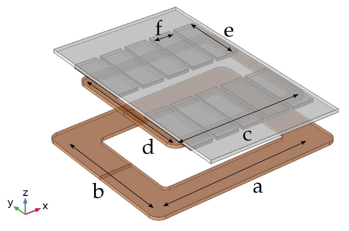
Figure 2 is considered. The coupling factor, which has to be determined depending on the position, was examined. Subsequently, the transmitted power was considered in an electrical simulation. To increase the transmitted power, in
Section 3.2, three identical transmitter and receiver coils are arranged next to each other and examined for the coupling factors and power transmission.
3.1. Single-Coil Power Transfer
To determine the coupling factors between a transmitting and a receiving coil, a simulation based on the fenite elements method (FEM) was performed. The simulation was performed in COMSOL Multiphysics, and the “magnetic fields” environment was used. An investigation into the lateral misalignment was carried out for a coil distance of 15 cm. As a result, different coupling factors were expected for different positions. The coupling factors were determined at intervals of 5 cm in both the x- and y-direction. Thus, a grid filled with coupling factors was obtained, which could later be used to simulate the transmission powers. The geometrical setup is shown in
Figure 2. The dimensions are given in
Table 3. On the primary side, there is a coil with a winding window of 10 cm. The secondary side consists of a secondary coil with multiple ferrite tiles placed above it. The last component is an aluminum shielding plate placed above the ferrite, representing the underbody of an electric car.
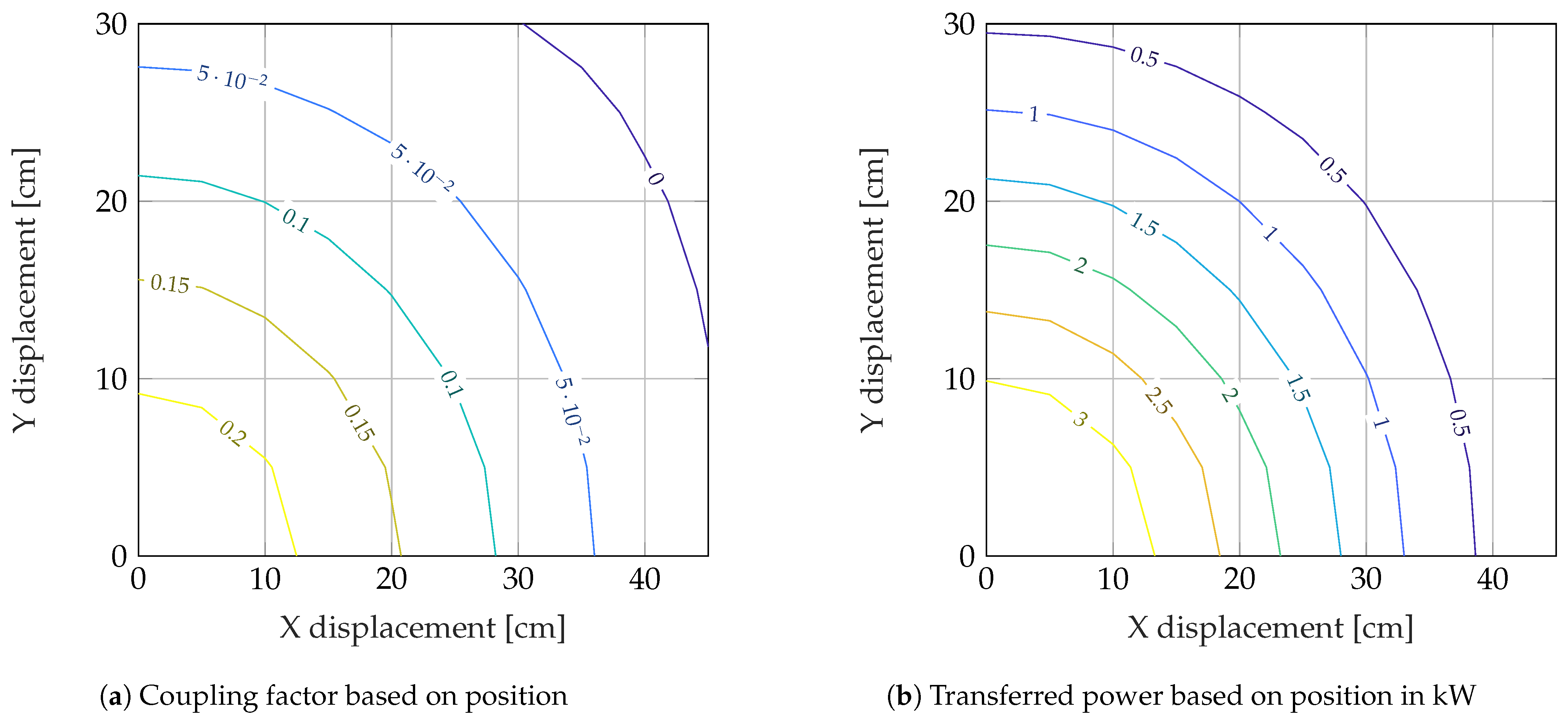
Figure 3a shows the resulting coupling factors based on the receiving coil position. The further the secondary coil moved away from the center of the primary coil, the lower the coupling factor between the coils became. Due to the smaller width of the primary coil in the y-direction, the coupling factor decreased faster by displacing in the y-direction rather than x-direction. The resulting coupling factors were transferred to an electrical simulation to evaluate the system behavior.
Figure 3b shows the power transmitted to the secondary coil. By using the LCC compensation, the power decreased as the coupling between the coils became smaller. The maximum power however was smaller than the power calculated in the system design from
Section 2. This can be explained by the fact that only the fundamental wave and no harmonics were considered in the calculation.
3.2. Parallel Power Transfer with Multiple Coils
To increase the transmitted power, three transmitting and receiving coils were connected in parallel.
Figure 4 shows the geometrical structure. The structures shown in
Figure 2 was placed next to each other three times with an x-displacement of 50 cm to obtain overlapping winding areas. The overlapping primary coils were driven in phase so that a large virtual coil was generated. This resulted in only a slightly varying resulting coupling factor
for an x-displacement of the secondary elements, as shown in
Figure 4.
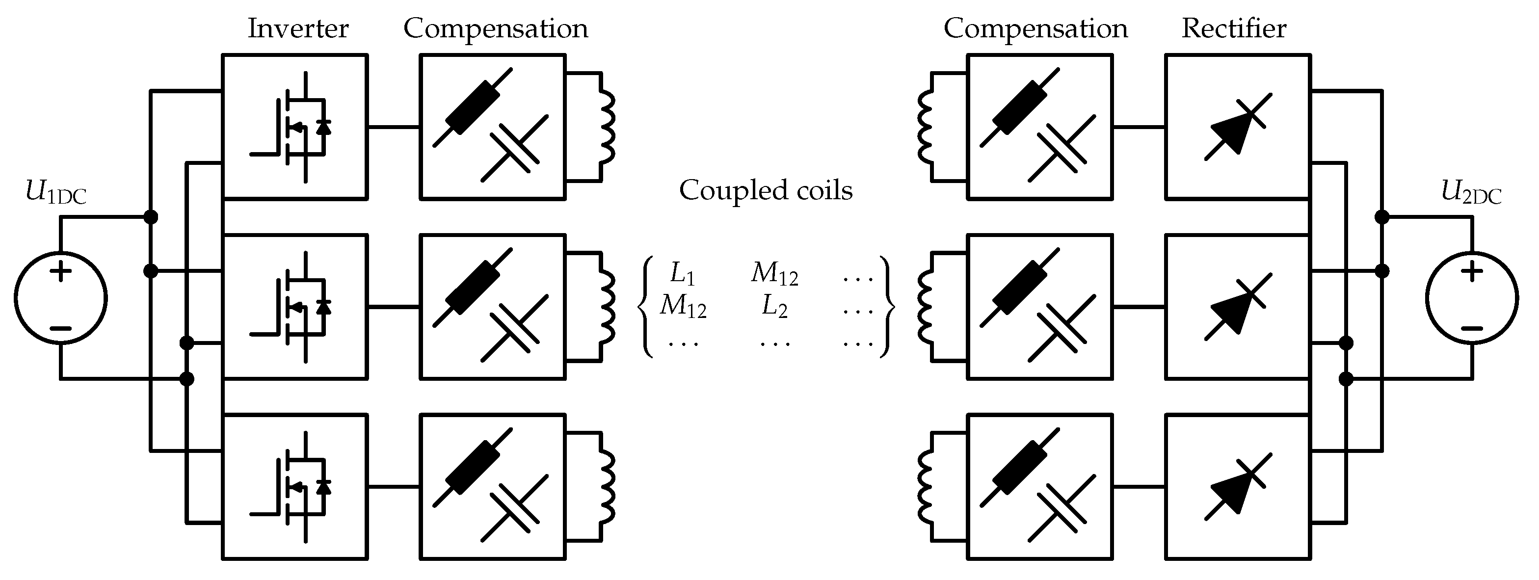
The result of the physical simulation was a coupling factor matrix, which represents the coupling of the individual coils to each other. Each one of these six coils had a coupling factor to the other five coils. By these results, an electrical simulation can be built using a model of the coupled coils. A schematic diagram of the electrical simulation is shown in
Figure 5. Each primary and secondary coil has its own compensation network, inverter, and rectifier. An input DC voltage of 300 V supplies the inverters. The generated square wave signal in combination with the LCC compensation provides a sinusoidal current in the coils, which are responsible for the energy transfer. As mentioned before, the field from each coil couples into all the other five coils and generates the induced voltages. The resulting currents on the secondary side are drawn from the individual coils in combination with the capacitors and rectifiers and feed a battery, which is represented by a DC voltage sink. If the secondary sides are too close too each other, the coupling effects become visible. Therefore, the individual receivers have to be decoupled.
3.2.1. Decoupling of the Secondary Coils
Figure 6 shows the entire setup from a side view. The distance
d describes the edge-to-edge distance between the conductors of the secondary coils.
According to the initial electrical simulations, small distances
d between the individual secondary sides had a negative effect on the power distribution in the secondary elements. If the distance
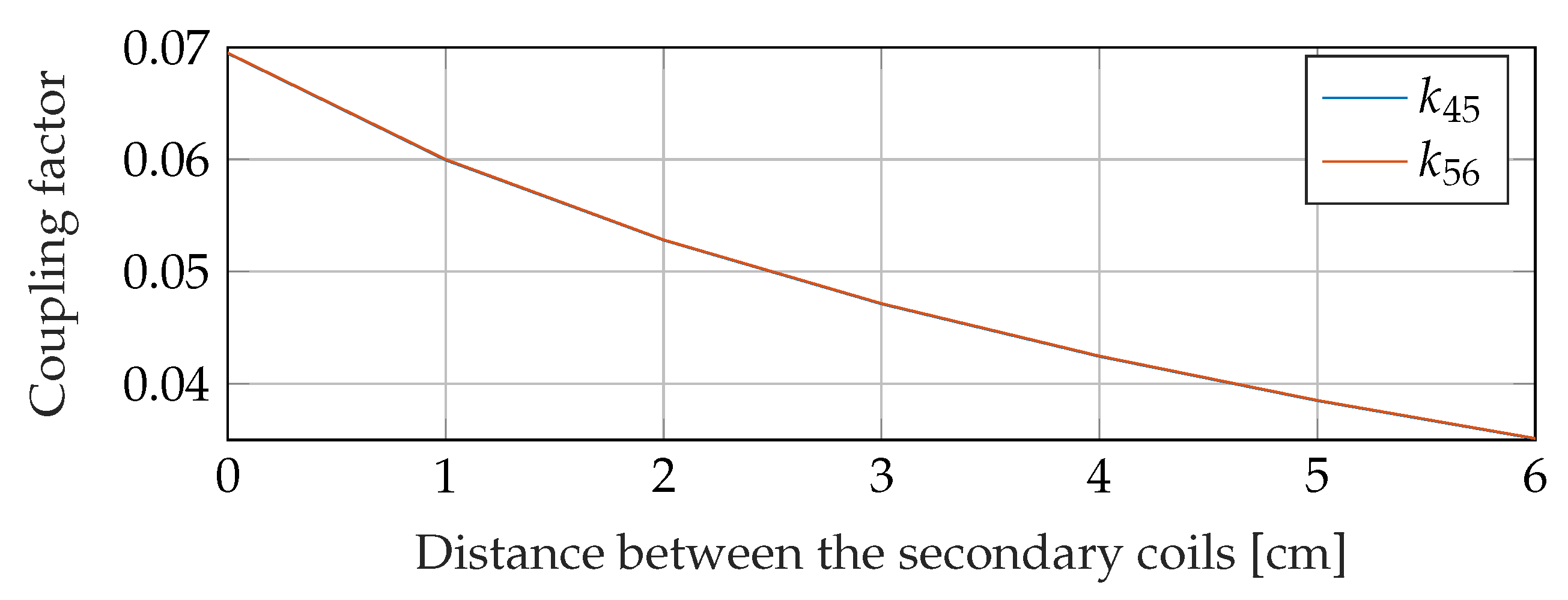
d increased later, the secondary elements effectively became shorter in order not to give up the central positioning above the primary elements. The two extreme scenarios considered with a distance of 0 cm and 6 cm are shown in
Figure 7. The coupling between the adjacent secondary Coils 4 and 5, as well as between Coils 5 and 6 is shown in
Figure 8. When the coils were placed directly next to each other without any spacing, significantly more power was drawn from the center Coil 5. The two adjacent elements couple to the middle unit through the fields they generate by themselves. This is shown in
Figure 9. To counteract the resulting behavior, the coils should be decoupled over an increasing distance between the coils. A uniform transmission power was only achieved by a distance
d greater than 3.5 cm, as shown in
Figure 9.
To continue the system simulation, a distance d of 6 cm was used to safely decouple the receivers. Due to the decoupling of the receivers, a position-based simulation can be performed to investigate the system behavior during the relocation of the receivers.
3.2.2. Electrical Simulation of the System
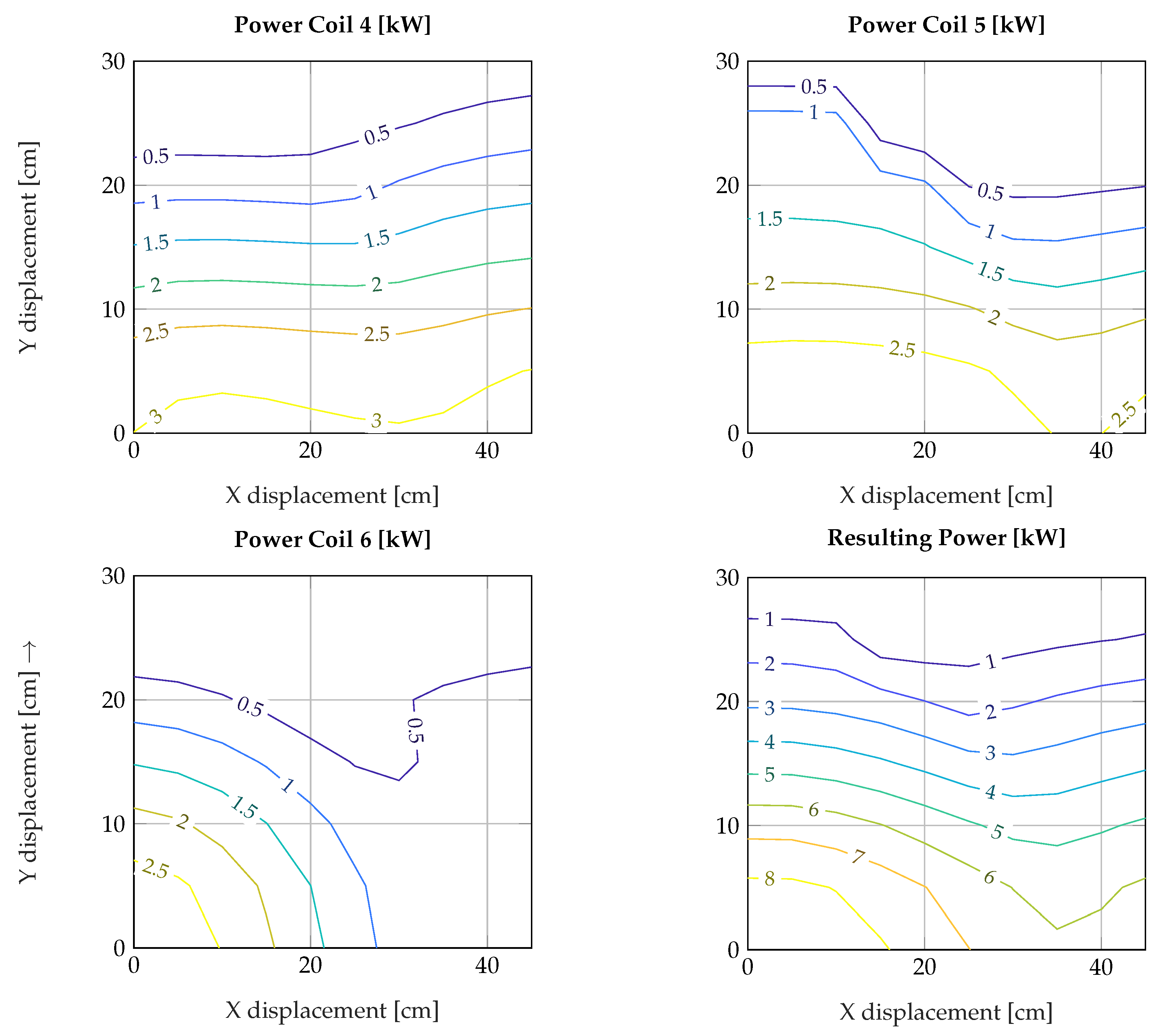
The results of the simulation are shown in
Figure 10. It is shown that the transferable power in all receiver coils decreased slightly compared to the single-transmitter–receiver system shown in
Figure 2. Multiple primary coils had a slightly negative impact on the transferable power. This can be explained by the joint coupling of the primary coils into a single secondary coil. Subsequently, the behavior of the system in the case of displacement in the x-, as well as the y-direction was considered. The transferred power decreased with an increasing y-offset of all secondary coils relative to the primary elements. If all three secondary elements were shifted equally in the x-direction, the power in Coils 4 and 5 changed only slightly. In Coil 6, however, the power decreased as it moved out of the field of Coil 3.
4. Discussion
In this work, two inductive power transfer systems were designed and simulatively examined. The first system consisted only of one transmitter and one receiver coil. Compared to the calculated values, the performance decreased. This was due to the fact that the calculations were carried out on the basis of a model, which only took the fundamental wave and no harmonics of the rectangular excitation signal into account. However, the influences of the third and fifth harmonics were recognizable at the inverter output. Nevertheless, the system showed good energy transfer behavior for charging electric vehicles, and the power decreased as expected with a lateral offset, as well as the coupling factor.
Ordinary systems, as proposed in the SAE J2954, have a significant advantage in the maximum transferable power due to the higher voltages on the vehicle side. For 48 V systems, the current in the coil and rectifier quickly reached very high values. Since high currents are difficult to handle and the power should be increased further, the system was expanded on a modular basis. The second system designed and investigated was a modular expandable system. The system was simulated as shown in
Figure 4. The primary sided single coils must be driven in phase to obtain a homogeneous field over the complete system length. If this is not the case, the performance would be drastically reduced. Even if the system was driven in phase, the performance did not exactly triple when three modules were used. The power decrease was explainable by the cross-coupling of the primary sides into a single secondary coil. As shown in
Figure 10, the individual power in the pickup coils was reduced compared to the single-coil power transfer system. However, due to the elongated design, the system had a significantly better offset tolerance in the x-direction. Not only the the cross-coupling of the primary into the secondary coils, but also the coupling of the secondary sides into each other caused problems in the energy transfer behavior. This was solved by increasing the distance between the secondary coils and slightly varying the coil size. In future research, the design procedure can be further investigated in order to include the harmonic influences in the design criteria. In addition, the influences of the modular system can be further investigated and mathematically analyzed to calculate the correct transmission powers already at the design stage. Furthermore, a control approach for the primary side can be designed in order to obtain an even distribution of the power despite the coupling of the secondary coils to each other. Additionally, the designed system can be built up to verify the results achieved by simulation. Especially the measured efficiency under real conditions can be examined, for example, to determine the usable working area with an efficiency >70%.
5. Conclusions
So far, only inductive power transfer systems for electric vehicles with high battery voltages have been developed and standardized. In this paper, a new modular inductive power transmission system for low-voltage electric vehicles was designed and simulatively validated. A method of designing a single-coil system was shown, and the behavior of one transmitting coil and one energy-receiving coil was simulated under misalignment. Increasing the power of the single-coil system further resulted in hard-to-handle high currents in the secondary coil and rectifier. Therefore, the system was extended by further primary and secondary units. The primary elements were driven in phase to ensure a homogeneous field distribution over the complete length of the primary coil arrangement. A problem was discovered in the coupling between the individual secondary sides. If the distance between the coils was too small, the power was not evenly distributed over the coils. This was counteracted by a gap between the secondary windings. After the decoupling of the secondary sides, the system was examined and evaluated for its transmission behavior with the offset of the receiver coils. It was shown that a parallel and, above all, modularly expandable approach in simulation is promising to increase the performance.
Author Contributions
Conceptualization, L.E. and J.N.; methodology, L.E. and N.P.; software, L.E.; validation, L.E. and J.N.; formal analysis, L.E., J.N. and N.P.; investigation, L.E.; resources, N.P.; data curation, L.E.; writing—original draft preparation, L.E.; writing—review and editing, J.N.; visualization, L.E. and J.N.; supervision, N.P.; project administration, N.P.; funding acquisition, L.E. and N.P. All authors have read and agreed to the published version of the manuscript.
Funding
This research was funded by Vector Stiftung.
Data Availability Statement
Conflicts of Interest
The authors declare no conflict of interest. The funders had no role in the design of the study; in the collection, analyses, or interpretation of data; in the writing of the manuscript; nor in the decision to publish the results.
References
- Liu, X. Qi standard wireless power transfer technology development toward spatial freedom. IEEE Circuits Syst. Mag. 2015, 15, 32–39. [Google Scholar] [CrossRef]
- Maier, M.; Maier, D.; Zimmer, M.; Parspour, N. A novel self oscillating power electronics for contactless energy transfer and frequency shift keying modulation. In Proceedings of the 2016 International Symposium on Power Electronics, Electrical Drives, Automation and Motion (SPEEDAM), Capri, Italy, 22–24 June 2016; pp. 67–72. [Google Scholar]
- Wireless Power Consortium. Qi-Mobile Computing—Wireless Power Consortium. Available online: https://www.wirelesspowerconsortium.com/qi/ (accessed on 26 January 2021).
- Zhang, Y.; Guo, Y.; Yan, B.; Wang, K.; Zhang, Z.; Wang, L. A Research on Characteristics of Bidirectional Wireless Power Transfer System. In Proceedings of the 2018 IEEE International Power Electronics and Application Conference and Exposition (PEAC), Shenzhen, China, 4–7 November 2018. [Google Scholar]
- Miller, J.M.; Onar, O.C.; Chinthavali, M. Primary-Side Power Flow Control of Wireless Power Transfer for Electric Vehicle Charging. IEEE J. Emerg. Sel. Top. Power Electron. 2015, 3, 147–162. [Google Scholar] [CrossRef]
- Parspour, N.; Maier, D.; Böttigheimer, M. Contactless energy transfer for charging electric and hybrid electric vehicles. In Proceedings of the 30th International Electric Vehicles Symposium and Exhibition, Stuttgart, Germany, 9–11 October 2017; pp. 3154–3161, ISBN 978-1-5108-6370-5. [Google Scholar]
- Kim, D.; Ahn, S.; He, Q.; Huang, A.; Fan, J.; Kim, H. Electric Parameter Tuning of Wireless Power Transfer Coil for Charging Interoperability of Electric Vehicles. In Proceedings of the 2020 IEEE International Symposium on Electromagnetic Compatibility & Signal/Power Integrity (EMCSI), Reno, NV, USA, 28 July–28 August 2020; pp. 619–622. [Google Scholar] [CrossRef]
- SAE Standard J2954. Wireless Power Transfer for Light-Duty Plug-In/Electric Vehicles and Alignment Methodology; SAE International: Warrendale, PA, USA, 2020. [Google Scholar]
- Witricity. Be in Charge. Making EV Charging Easier than Refueling. Available online: https://witricity.com/ (accessed on 17 September 2021).
- Nimri, R.M.; Kamineni, A.; Zane, R. A Modular Pad Design compatible with SAE J2954 for Dynamic Inductive Power Transfer. In Proceedings of the 2020 IEEE PELS Workshop on Emerging Technologies: Wireless Power Transfer (WoW), Seoul, Korea, 15–19 November 2020; pp. 45–49. [Google Scholar] [CrossRef]
- Shin, J.; Song, B.; Lee, S.; Shin, S.; Kim, Y.; Jung, G.; Jeon, S. Contactless power transfer systems for On-Line Electric Vehicle (OLEV). In Proceedings of the 2012 IEEE International Electric Vehicle Conference, Greenville, SC, USA, 4–8 March 2012. [Google Scholar]
- Zhang, Y.; Guo, Y.; Wang, L.; Bo, Q. Design of Dual-Side LCC Compensation Networks Considering Rectifier Equivalent Inductance for Wireless Power transfer System. In Proceedings of the 2020 IEEE PELS Workshop on Emerging Technologies: Wireless Power Transfer (WoW), Seoul, Korea, 15–19 November 2020; pp. 210–213. [Google Scholar]
- Maier, D.; Heinrich, J.; Zimmer, M.; Maier, M.; Parspour, N. Contribution to the System Design of Contactless Energy Transfer Systems. IEEE Trans. Ind. Appl. 2019, 55, 316–326. [Google Scholar] [CrossRef]
- Maier, D.; Noeren, J.; Parspour, N.; Lauer, C. A novel power electronics for contactless inductive energy transfer systems. In Proceedings of the 2018 IEEE 18th International Power Electronics and Motion Control Conference (PEMC), Budapest, Hungary, 26–30 August 2018. [Google Scholar]
- Khalilian, M.; Guglielmi, P. Primary-Side Control of a Wireless Power Transfer System with Double-Sided LCC Compensation Topology for Electric Vehicle Battery Charging. In Proceedings of the 2018 IEEE International Telecommunications Energy Conference (INTELEC), Turino, Italy, 7–11 October 2018. [Google Scholar]
- Cha, H.-R.; Park, K.-H.; Choi, Y.-J.; Kim, R.-Y. Double-Sided LCC Compensation Topology with Semi-Bridgeless Rectifier for Wireless Power Transfer System. In Proceedings of the 2019 10th International Conference on Power Electronics and ECCE Asia (ICPE 2019—ECCE Asia), Busan, Korea, 27–30 May 2019; pp. 1–6. [Google Scholar] [CrossRef]
| Publisher’s Note: MDPI stays neutral with regard to jurisdictional claims in published maps and institutional affiliations. |
© 2021 by the authors. Licensee MDPI, Basel, Switzerland. This article is an open access article distributed under the terms and conditions of the Creative Commons Attribution (CC BY) license (https://creativecommons.org/licenses/by/4.0/).

