Article

IEC 61850-Based Communication Networks of Distribution System against Cyber and Physical Failures

1
Electric Engineer and Researcher, Department of Electrical Power and Machines Engineering, Helwan University, Helwan 11731, Egypt
2
Department of Electrical Power and Computer Engineering, Clemson University, Clemson, SC 29630, USA
3
Department of Electrical Power and Computer Engineering, Florida International University, Miami, FL 33174, USA
*
Author to whom correspondence should be addressed.
World Electr. Veh. J. 2021, 12(3), 155; https://doi.org/10.3390/wevj12030155
Submission received: 26 May 2021 / Revised: 4 September 2021 / Accepted: 13 September 2021 / Published: 15 September 2021

Abstract

:
This paper proposes a decentralized control approach using a co-simulation platform to monitor protective elements and provide complete protection scheme for distribution systems. Real time measurements are obtained by interfacing the system model in RSCAD/RTDS with SEL 421 protective relays and publish/subscribe the voltage and current signals of the buses and transmission lines based on IEC 61850 communication protocol to isolate the fault correctly. The proposed technique helps to identify the location of the fault and introduces primary and buck protection for the system. The communication networks assists in facing cyber and physical threats and finding a new path for healthy relays to remove faults from the system. This technique is investigated on an IEEE 14 bus system for all possible fault locations. The proposed scheme can clear the fault by isolating the minimum part of the system and improving the endurance of the power in it. The system shows the smooth information flow between the cyber and physical parts to isolate faults in it in different cases.

1. Introduction

Communication networks introduced several advantages to the protection system to deliver electricity to the customer safely; however, they added some challenges that should be taken into consideration to design a suitable protection scheme. The main problems that engineers may face to configure the network is the vulnerability of the grid and attacks to the communication signals that can be transferred between the protective relays. It is clear that mitigating the effects of the cyber and physical attacks is an important task to avoid mal-operation in the network system [1]. The most promising standard that can be used to communicate between the Intelligent Electronic Devices (IEDs) suffers from such threats, and dealing with these problems requires a robust communication system to send/receive Generic Oriented Object Substation Event (GOOSE) and Sampled Measurement Values (SMV) messages and trip the appropriate breaker. Several reasons contributed to causing severe impacts on the network; one of the reasons was nature, such as in the case of the Sandy and Katrina hurricanes that caused huge losses in the power network and damaged a large number of towers. Beside physical attacks, we have also cyber-attacks that may cause unintentional opening of the circuit breakers and produce instability in the system network and outage of power that can be delivered to the customer. We can conclude from this that designing a system to face such cyber and physical attacks is important to increase the resiliency and reliability of the system [2].
The authors in [3] presented an overview of the cyber security topic for the smart grid. A solution to the false data injection to reduce the threats to the power systems was introduced in [4]. To improve the performance of the hosts and network system, an anomaly detection technique was presented in [5].
An attack scenario was performed on the differential relays technique [6], and a security method was investigated to avoid mal-operation on that technique. In [7,8,9], attacks were discussed in different protection schemes, such as distance protection, and a method based on deep learning was discussed in [10] to mitigate the effects of the attacks. An extensive study of how to perform cyber security within IEC 61850 communication protocol was presented in [11,12]. The neural network can be used to investigate the mal-operation in the relay and breaker due to malicious messages. In [13], the authors presented a real time method to accurately determine the fault location and possibility of tripping the breaker due to cyber-attacks in the relays. By comparing the calculated and estimated imposed voltage signals at the line’s current differential relays, the authors in [14] succeeded in detecting the false data injection. As a complement to the efforts to mitigate the cyber and physical attacks, this paper presents a protection technique to face such attacks.
The contribution of the paper can be summarized as follows:
  • Introduce a co-simulation platform to link between the system model on RSCAD/RTDS and SEL 421 protective relays.
  • Publish/subscribe SV/GOOSE messages between the system model and the external relays to provide a protection scheme for the distributed system
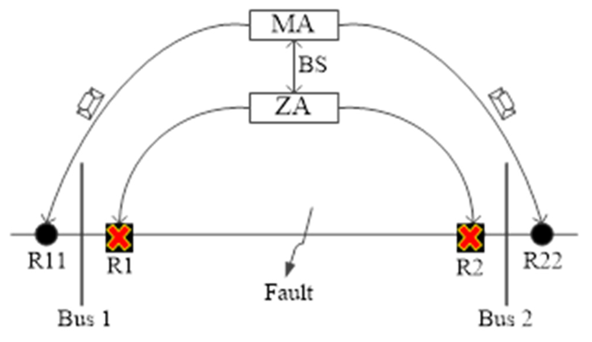
  • Divide the system into several agent zones and send the voltage of each bus to the agents as SV message. Based on the under-voltage technique, the agents send a GOOSE message to the breakers.
  • Two solutions are suggested to mitigate the effects of failure in the communications signals and enhance the resiliency of the system.
The paper is organized as follows: Section 2 introduces the different challenges to design an adequate protection scheme for the system network. Section 3 presents the proposed protection technique. Section 4 discusses the simulation cases and the results. Finally, Section 5 concludes the paper.

2. Protection Issues in the Network System

2.1. Selectivity and Sensitivity Features

Selectivity and sensitivity functions should be considered when designing a suitable protection scheme for a system capable of operating in different modes. The selectivity term is measured by the system’s ability to define the fault location and identify the fault zone, whether internal or external. For a system that may operate under several modes of operations, the suggested protection strategy should identify the fault conditions. The system should switch to operating in an islanded mode for any grid faults and protect the different equipment in the system. During the stand-alone operation of the system, the protection scheme is responsible for isolating the faulted section and keeping the system operating under stable conditions. Sensitivity means that the protective devices should detect the fault conditions in the system. The protection scheme’s main objective is to detect the fault and remove it from the system as fast as possible to reduce the damage to the equipment by opening the appropriate circuit breakers. Adjusting the sensitivity of the protection devices should be achieved without negatively impacting the selectivity of the protection scheme [15].

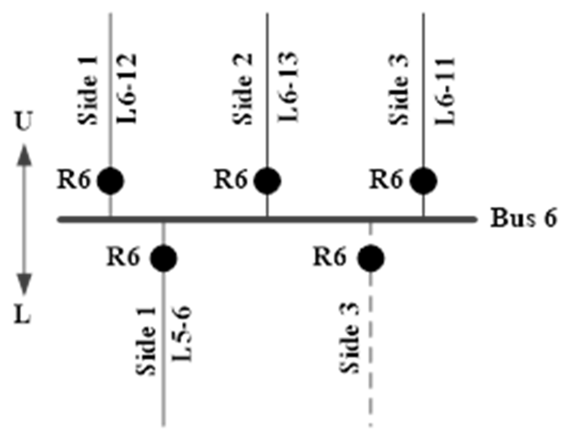
2.2. Direction of Power Flow in the Relays

There are several advantages to using DERs for supplying energy and supporting the power to the grid. However, the system introduced several challenges in terms of an adequate protection scheme as the direction of the power changes from unidirectional to bidirectional operation. The bidirectional power flow can pose challenges in coordinating between the protective devices. The traditional methods used to operate the primary relays and then allow a time-delayed operation of a backup relay may no longer be feasible as the topology changes; the power system is no longer radial when the DGs are connected and supplying power to the system. Due to the high penetration of DERs in the system, the legacy protection scheme is no longer suitable to protect the system. Operation of DGs affects the protection scheme and may cause false tripping of feeders and increase or decrease in the fault level depending on the status of the DGs. The changing fault levels can affect the reach of the overcurrent relay leading to miss-coordination [16].

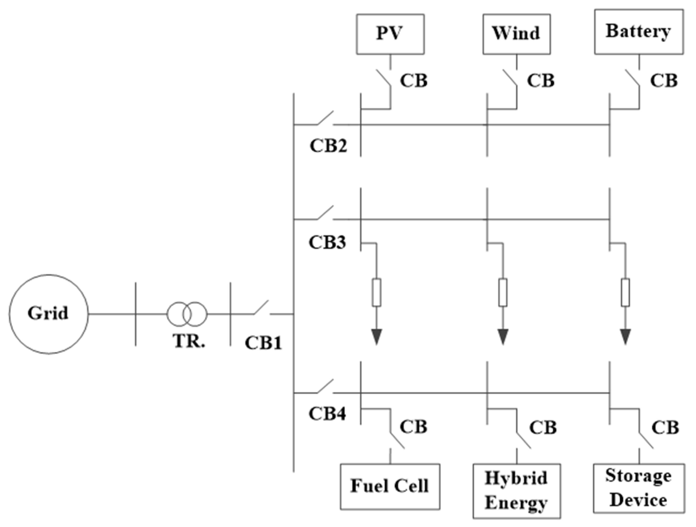
2.3. Architecture of the System

The system’s architecture can change for many reasons, such as connecting or disconnecting DGs, shutting down several loads, and importing power to the grid, as shown in Figure 1. Dynamic changes in the system configuration and the status of the DGs mean that the protection scheme must be updated to face the challenges that arise in different system configurations. The communication networks play an essential role in helping the relays to update their settings based on the present scheme and detect the fault section correctly. Centralized and decentralized communication networks have been presented to share the information between the IEDs, and different protocols are used to map the data. One of the most promising protocols is IEC61850, which can transfer the data into GOOSE, SV and MMS protocols and collect the data from different locations in the system [17].

2.4. Nuisance Tripping

Due to the high penetration of DGs, the possibility of tripping a healthy feeder is high when the fault happens at the adjacent fault. Figure 2 shows a simple case where the fault occurs on feeder 1. For a fault on feeder 1, the relay R1 should trip first, but due to the high contribution from DG to R2 during the fault, it can trip before R1, causing a miss operation and isolating the healthy feeder 2. A communication link can be used to coordinate between relays R1 and R2, allowing relay R1 to operate before relay R2 [18].

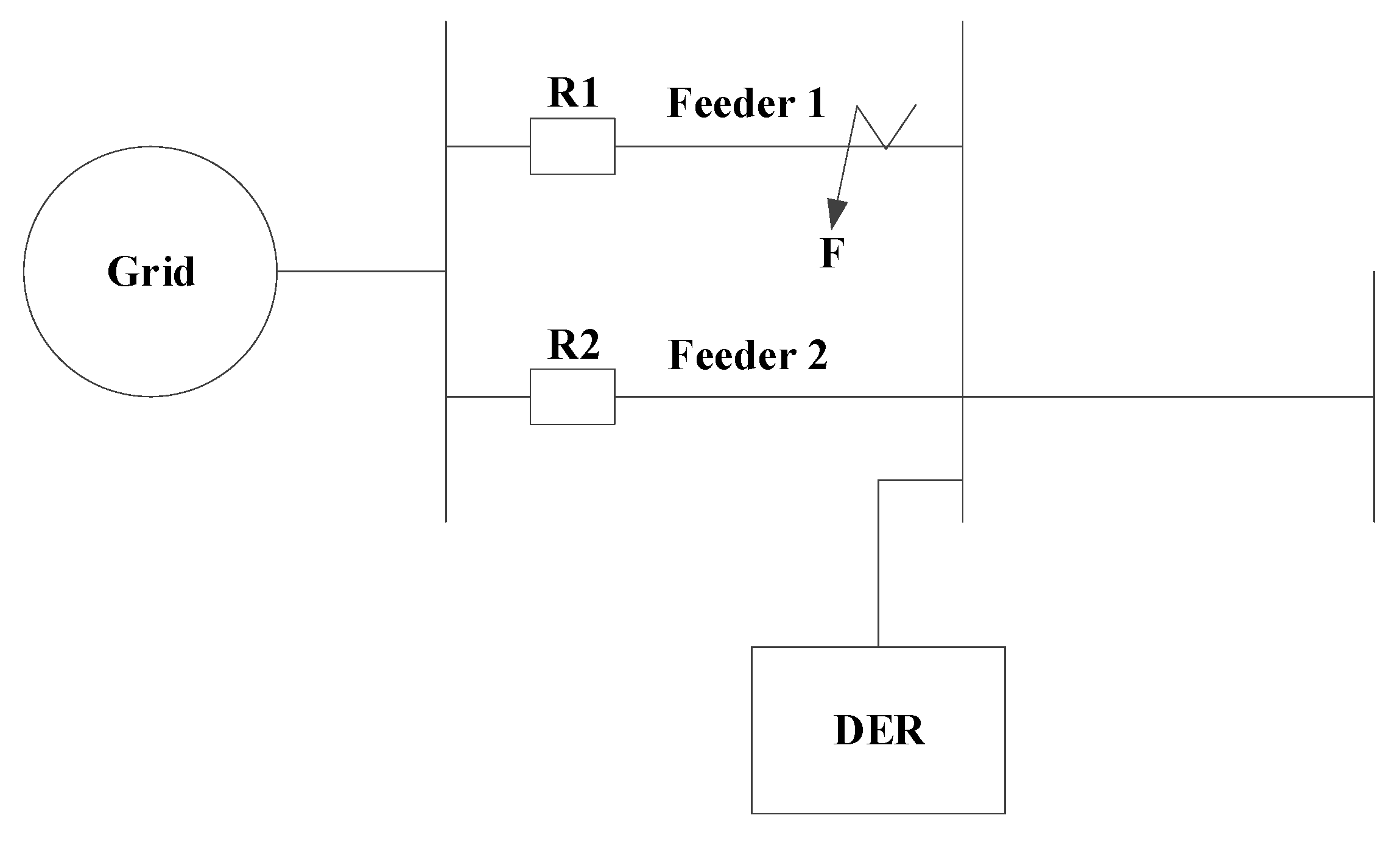
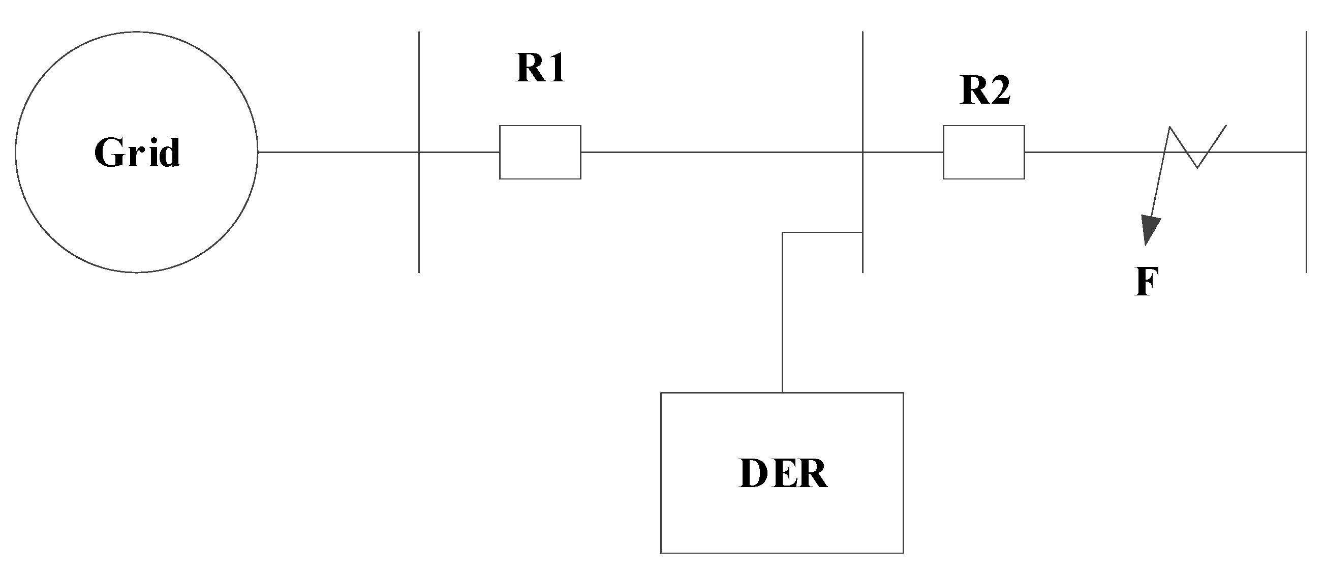
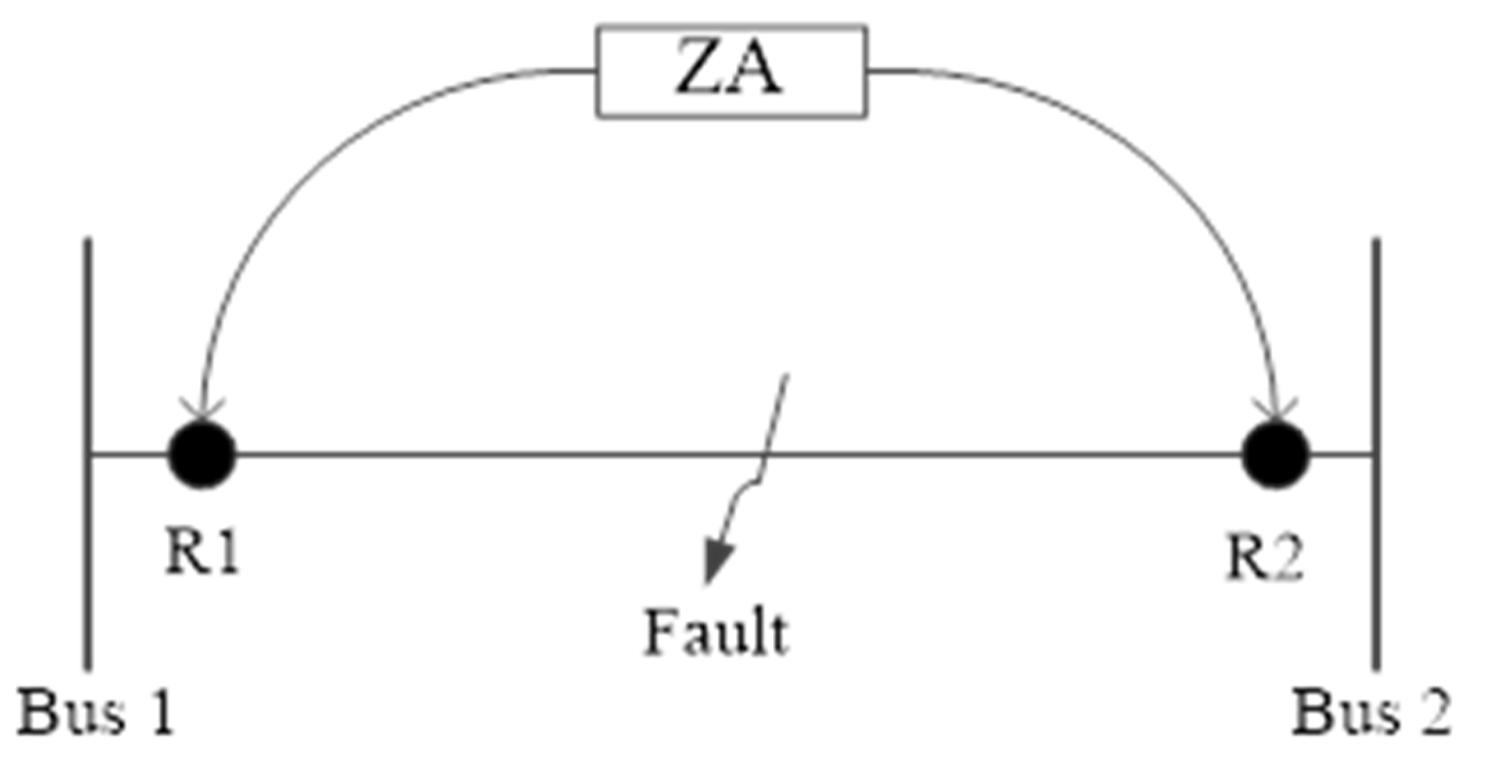
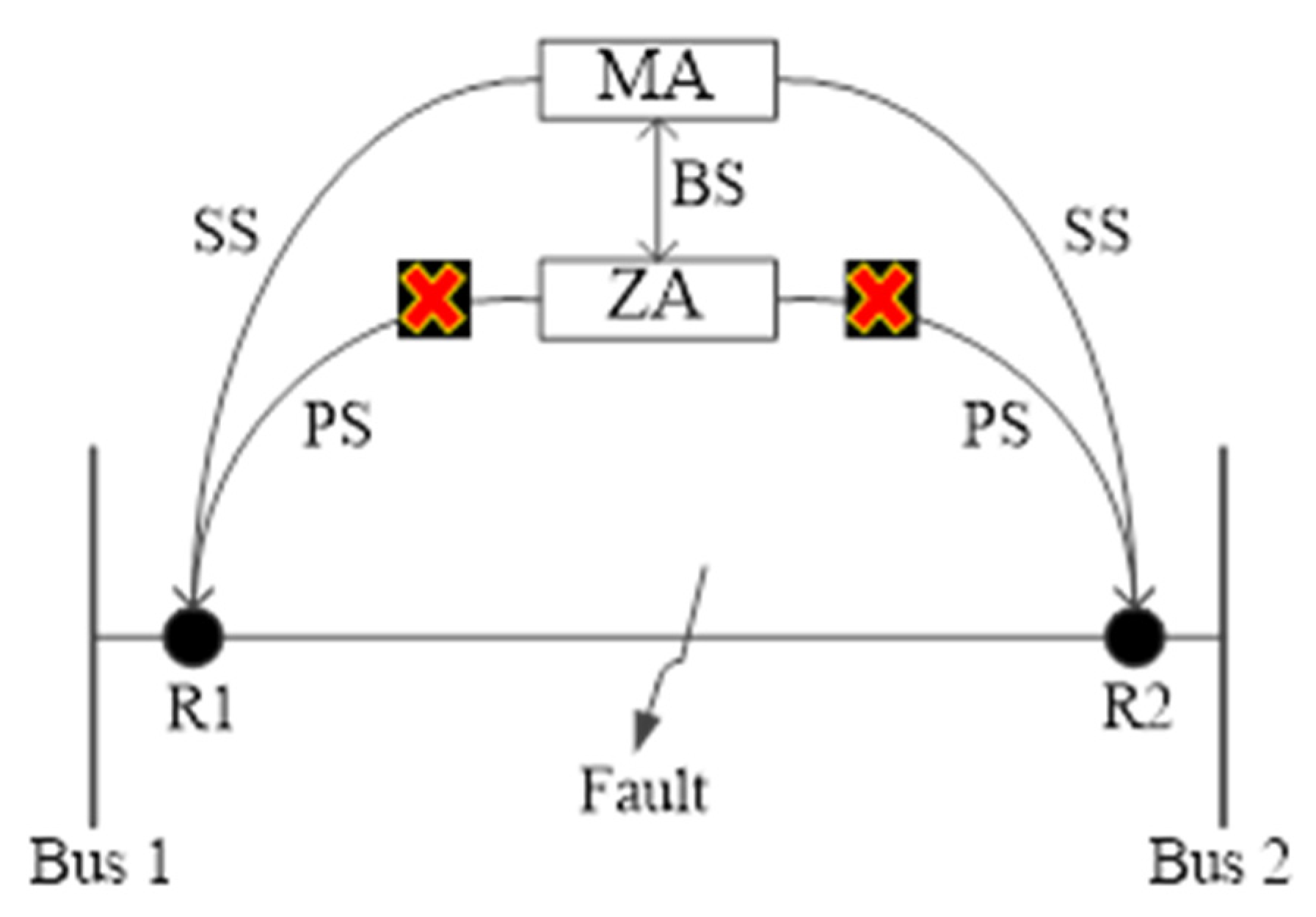
2.5. Protection Blinding Phenomena

DGs change the current flow to be bidirectional, increasing the difficulty of designing a suitable protection scheme and reducing the relays’ reach. Figure 3 highlights this issue, assuming a fault occurs at the far end. The relay R2 should isolate that fault, but the upstream relay R1 underreaches the fault blinding it for the fault, which stops it from acting as a backup to relay R1. This effect on the sensitivity of R1 is called protection blinding [17].

3. Platform of the Protection Technique

3.1. IEC 61850 Communication Protocol

This communication protocol is used to organize the data transferred between IED’s across the Local Area Network (LAN) system. It is global standard to confirm the interoperability between the IEDs from serval vendors, and the main function of that standard is to break the core of the IEDs into several logical nodes. Each logic node presents a certain function of the physical device. IEC 61850 maps the data into three different protocols, and GOOSE that is fast and non-routable multicasts and transfers over layer 2 of the Open Systems Interconnection (OSI). It can be used for the critical operation in the power system such as protection of the power line. The main feature of the GOOSE message is to receive it within 4 ms from the publisher to trip the circuit breaker. Moreover, SMV is another protocol that is used in the real time operation to digitalize the voltage and current signals through the process bus between IEDs. IEC 61850 recommended to transfer the electrical signals in 80 sample/s for 60 HZ voltage and current signals. It follows a publisher and subscriber model and sends within 4 ms. Manufacture Message System (MMS) is the third protocol, and it can be used for control and optimization purposes as there is no time constant to send that message and follow a client and server model [19]. The major problem of IEC 61850 is the threats of attacks, some of those attacks can be shown in Figure 4.

3.2. Proposed Protection System

IEEE 14 bus system is used to investigate the proposed protection scheme. A co-simulation platform is created to connect between the cyber and physical parts. The system is modeled in RSCAD and emulated in RTDS to obtain real time measurements for the voltage and current signals that are required to perform the protection scheme. The signals are transferred from RTDS through GTNETx2 interface and received to the commercial protective relays 421 edition 7 that have the feature to receive SV messages. Based on the proposed protection strategy (under voltage method), the protective relays send GOOSE messages and trip the appropriate circuit breakers in the system model. More explanation of how to publish/subscribe the standard protocols GOOSE/SV messages can be found in [19].
Figure 5 shows the proposed protection idea on IEEE 14- bus network (information about the system can be found in [16]). As it can be noted in this figure, the system is divided into two zones. The voltage of each bus is sent to the Main Agent (MA) and the agent of each zone 1 (ZA1) and the agent of zone 2 (ZA2). During the normal operation, the voltages are changed within the accepted nominal values, while the fault will cause dropping in the voltages of the corresponding buses and identify the fault location. In order to identify the fault location and the faulty transmission line and accordingly the protective relays that will operate to isolate the fault correctly, Figure 6 shows the transmission lines that are connected to bus 6. We identified the relays that are connected to bus 6 to be at two directions (Upper (U) and Lower (L)). For the upper direction, we have three relays identified by side (1) (the left side), the middle leg (2) and the right side (3). On the other hand, we have one transmission line in Figure 5 (L56) identified by R6 in side 1. We added another transmission line in Figure 6 and determined that the relay is located in side 3 as we need to certain side 2 to the middle leg. Assume that we have a fault at the transmission line between bus 6 and bus 12 (L6–12); based on that order, the relay should be operated to isolate the fault is R6 located in the upper direction and determined by side 1.

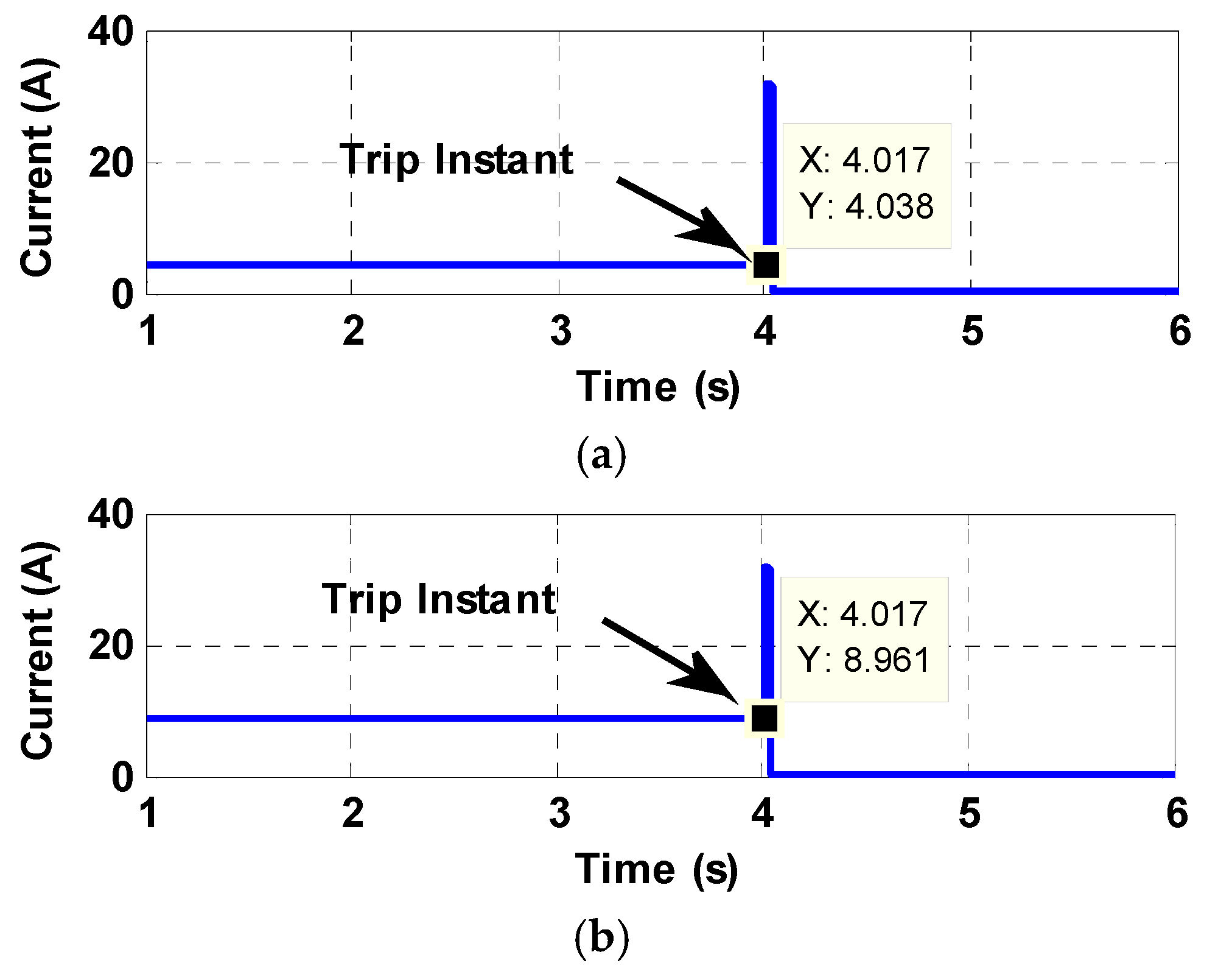
4. Simulation Case Studies

This section introduces several case studies to investigate the system performance. As shown in Figure 7, the ZA obtain the SV messages from RTDS and issue GOOSE message to both relays that are located in the system model and isolate the fault from the system. Different types of attacks may occur in the proposed system like cyber and physical attacks. The cyber-attacks may happen in the signals that are transferred between the relays and ZA and back up protection is suggested to deal with such type of attack. The physical attack may happen when the corresponding relays that should operate to isolate the fault are not available at fault condition; that case will be discussed in the last case study followed by a suitable solution to isolate the fault properly from both sides of the fault line.
Case (1): System performance at fault condition
This case explains the occurrence of the fault in the transmission line that connected between buses 6 and 12. When the fault happens, the voltages of buses 6 and 12 drop and are sent to the ZA2 as SV messages. ZA2 identified the fault location, and according to the last explanation regarding the protective relays that should operate to isolate the fault, ZA2 sent GOOSE messages to the corresponding relays. Figure 8a showed that R6, located in the upper direction at side 1, is tripped at t = 4 s. In order to isolate the fault completely from the system, R12 in the lower direction and located at side 1 is tripped at t = 4 s as it can be shown in Figure 8b.
Case (2): Cyber Attack
Figure 9 shows the case of cyber-attack of the GOOSE signals (Primary Signals (PS)) between ZA and the protective relays. ZA identified the fault but could not send the PS to the relays. In this case, MA communicated with ZA through buck up signals (BS), and the fault location was identified as MA was receiving the voltages of the buses. MA is operated as a secondary protection agent, and it sent GOOSE signals (Secondary Signals (SS)) to the corresponding relays as shown in Figure 9.
Figure 10 shows the performance of the system when the fault occurred between the buses 6 and 12, and ZA2 could not send the GOOSE messages. MA presented a secondary solution for this case and send a GOOSE message to R6 in the upper direction at side 1 and tripped at t = 4.017 s. MA is responsible for sending another GOOSE message to the R12 in the lower direction, which is side 1 and is tripped at t = 4.017 s to isolate the fault from the system. Several cases were performed at the transmission lines in the system to investigate the proposed protection scheme for this case study. As shown in Table 1, ZA1, ZA2 and MA can detect the fault location from the right side (side 1), middle side (side 2) and left side (side 3) to isolate the fault completely from the system.
Fault at L12 was located between buses 1 and 2, and it can be noted that the candidate relays for the primary protection are R1 in side 1 and lower direction from the first terminal and R2 in side 1 and lower direction from the other terminal. To protect the system from a cyber-attack that may happen in the communications between ZA and their relays at both zones, we added a new communication link between ZA and MA. For the same fault location, a slight delay to trip the circuit breakers as MA sent GOOSE messages to the same relays.
Case (3): Physical Attack
Another solution can be presented to the failure of the primary relays. At fault condition, the ZA could not send GOOSE signals (PS) due to physical problem in the operation of the relays. ZA is communicated with MA through BS and send GOOSE Signals (SS) to the nearest healthy relays and isolated the fault from both sides as shown in Figure 11.
Figure 12a shows the operation of the system when the fault happened between buses 6 and 12. In this case, the abovementioned relays were not operated, and the fault was still effected in the system. ZA2 is communicated with the MA and asked to trip the nearest relays to remove the fault from the system. As MA received the voltage of the buses and informed about the location of the fault, MA found out that the nearest protective relays that can protect the system from that fault are R6 but located at the upper direction and side 2 (middle leg) and R12, lower direction and side 3 from the other terminal as shown in Figure 12b. Many cases were studied for the physical attack problem that maybe occurred in the protective relays and are summarized in Table 2. Table 2 shows the faults in the possible transmission lines in the system and identifies the operating relays for each fault. Through the buck up communication link between ZA and MA, a new path to the healthy relays is available to isolate the fault successfully and protect the system from that threat.
As it was explained previously, the voltage from each terminal of the transmission line was sent to ZA1, ZA2 and MA as SV messages and responded back to the simulation by GOOSE messages to isolate the fault from the system.
Again, L12 is introduced to show the primary and the secondary protective relays with the tripping times at both cases.
For the primary case, R1-side 1 and lower direction is the best candidate to remove the fault from that terminal. On the other hand, R2-side 1 and upper direction is the relay that should operate to complete isolate the system from that fault. In case the last-mentioned relays fail to operate, MA ask the R1 from side 1 and lower direction to buck up R1 from side 1 and lower direction. Moreover, R2 from side 1 and lower direction supported the failure of R2 from side 1 and upper direction.

5. Conclusions

This paper suggested a co-simulation framework and linking between a simulated model in RSCAD/RTDS and external protective relays to provide a protection scheme for IEEE 14 bus system. Two solutions were presented to face the cyber and physical threats in the system. MA was communicated to the Agent of each zone and provided suitable buck up protection for the case studies. Several faults were applied in the transmission lines to show the capability of the suggested protection scheme. The communication networks helped to find new paths for the failure of the primary protective elements in the system and provide fast and reliable connections between the MA and the different relays to isolate the fault correctly from the system. In all the case studies presented, cyber information flow and physical dynamics of the power system were recorded and the interrelation between them was properly analyzed.

Author Contributions

The authors confirm contribution to the paper as follows: study conception and design—N.F., H.F.H.; data collection—N.F., H.F.H., O.M.; analysis and interpretation of results—N.F., H.F.H.; draft manuscript preparation—N.F., H.F.H., O.M. All authors have read and agreed to the published version of the manuscript.

Funding

This research received no external funding.

Data Availability Statement

All data and models measured or used during the study appear in the body of the manuscript.

Conflicts of Interest

The authors declare no conflict of interest. This is to disclose that there is no financial interest or benefit arising from the direct applications of this research.

References

  1. Ameli, A.; Hooshyar, A.; El-Saadany, E.F. Development of a cyber resilient line current differential relay. IEEE Trans. Ind. Inform. 2018, 15, 305–318. [Google Scholar] [CrossRef]
  2. Fawzy, N.; Habib, H.F.; Mokhtari, S. Performance Evaluation of Electric Vehicle Model under Skid Control Technique. World Electr. Veh. J. 2021, 12, 83. [Google Scholar] [CrossRef]
  3. Yan, Y.; Qian, Y.; Sharif, H.; Tipper, D. A survey on cyber security for smart grid communications. IEEE Commun. Surv. Tuts. 2012, 14, 998–1010. [Google Scholar] [CrossRef] [Green Version]
  4. Hahn, A.; Ashok, A.; Sridhar, S.; Govindarasu, M. Cyber-physical security testbeds: Architecture, application, and evaluation for smart grid. IEEE Trans. Smart Grid 2013, 4, 847–855. [Google Scholar] [CrossRef]
  5. Hong, J.; Liu, C.C.; Govindarasu, M. Integrated anomaly detection for cyber security of the substations. IEEE Trans. Smart Grid 2014, 5, 1643–1653. [Google Scholar] [CrossRef]
  6. Bulbul, R.; Gong, Y.; Ten, C.W.; Ginter, A.; Mei, S. Impact quantification of hypothesized attack scenarios on bus differential relays. In Proceedings of the 2014 Power Systems Computation Conference, Wroclaw, Poland, 18–22 August 2014; pp. 1–7. [Google Scholar]
  7. Jahromi, A.A.; Kemmeugne, A.; Kundur, D.; Haddadi, A. Cyber physical attacks targeting communication-assisted protection schemes. IEEE Trans. Power Syst. 2020, 35, 440–450. [Google Scholar] [CrossRef]
  8. Habib, H.F.; Fawzy, N.; Brahma, S. Performance Testing and Assessment of Protection Scheme Using Real-Time Hardware-in-the-Loop and IEC 61850 Standard. IEEE Trans. Ind. Appl. 2021, 57, 4569–4578. [Google Scholar] [CrossRef]
  9. Liu, X.; Shahidehpour, M.; Li, Z.; Liu, X.; Cao, Y.; Li, Z. Power system risk assessment in cyber attacks considering the role of protection systems. IEEE Trans. Smart Grid 2017, 8, 572–580. [Google Scholar] [CrossRef]
  10. Habib, H.F.; Fawzy, N.; Esfahani, M.M.; Mohammed, O.A. Enhancement of Protection Scheme for Distribution System Using the Communication Network. In Proceedings of the 2019 IEEE Industry Applications Society Annual Meeting, Baltimore, MD, USA, 29 September–3 October 2019. [Google Scholar]
  11. Yang, Y.; Jiang, H.T.; McLaughlin, K.; Gao, L.; Yuan, Y.B.; Huang, W.; Sezer, S. Cybersecurity test-bed for IEC 61850 based smart substations. In Proceedings of the IEEE Power Energy Society General Meeting, Denver, CO, USA, 26–30 July 2015; pp. 1–5. [Google Scholar]
  12. Kabir-Querrec, M.; Mocanu, S.; Thiriet, J.; Savary, E. A Test bed dedicated to the Study of Vulnerabilities in IEC 61850 Power Utility Automation Networks. In Proceedings of the 2016 IEEE 21st International Conference on Emerging Technologies and Factory Automation (ETFA), Berlin, Germany, 6–9 September 2016; pp. 1–4. [Google Scholar]
  13. Esmaeilian, A.; Popovic, T.; Kezunovic, M. Transmission line relay mis-operation detection based on time-synchronized field data. Electr. Power Syst. 2015, 125, 174–183. [Google Scholar] [CrossRef]
  14. Habib, H.F.; Fawzy, N.; Mohammed, O.A. A Fault Clearing for Microgrid Protection System Utilized the Communication Network with Centralized Approach. In Proceedings of the 2019 SoutheastCon, Huntsville, AL, USA, 11–14 April 2019. [Google Scholar]
  15. Mokhtari, S.; Abbaspour, A.; Yen, K.K.; Sargolzaei, A. Neural Network-Based Active Fault-Tolerant Control Design for Unmanned Helicopter with Additive Faults. Remote Sens. 2021, 13, 2396. [Google Scholar] [CrossRef]
  16. Habib, H.F.; Fawzy, N.; Esfahani, M.M.; Mohammed, O.A.; Brahma, S.; Habib, N.F.K. An Enhancement of Protection Strategy for Distribution Network Using the Communication Protocols. IEEE Trans. Ind. Appl. 2020, 56, 1240–1249. [Google Scholar] [CrossRef]
  17. Fawzy, N.; Habib, H.F.; Mohammed, O.; Brahma, S. Protection of Microgrids with Distributed Generation based on Multiagent System. In Proceedings of the 2020 IEEE International Conference on Environment and Electrical Engineering and 2020 IEEE Industrial and Commercial Power Systems Europe (EEEIC/I&CPS Europe), Madrid, Spain, 9–12 June 2020; pp. 1–5. [Google Scholar] [CrossRef]
  18. Shah, R.; Goli, P.; Shireen, W. Adaptive Protection Scheme for a Microgrid with High Levels of Renewable Energy Generation. In Proceedings of the 2018 Clemson University Power Systems Conference (PSC), Charleston, SC, USA, 4–7 September 2018; pp. 1–7. [Google Scholar] [CrossRef]
  19. Habib, H.; Fawzy, N.; Brahma, S. Hardware in the Loop Testing of a Protection Scheme for Microgrid using RTDS with IEC 61850 Protocol. In Proceedings of the 2020 IEEE Industry Applications Society Annual Meeting, Detroit, MI, USA, 10–16 October 2020; pp. 1–8. [Google Scholar] [CrossRef]
Figure 1. Configuration of the inverter-based system.
Wevj 12 00155 g001
Figure 2. Nuisance tripping.
Wevj 12 00155 g002
Figure 3. Fail to trip operation.
Wevj 12 00155 g003
Figure 4. Threats of attacks inside/outside the station.
Wevj 12 00155 g004
Figure 5. IEEE 14 bus system.
Wevj 12 00155 g005
Figure 6. Relays of bus 6.
Wevj 12 00155 g006
Figure 7. Messages between ZA and relays.
Wevj 12 00155 g007
Figure 8. System performance (a) R6 and (b) R12.
Wevj 12 00155 g008
Figure 9. Messages between MA and ZA and the relays for cyber-attack.
Wevj 12 00155 g009
Figure 10. System performance: (a) R6 and (b) R12 for cyber-attack.
Wevj 12 00155 g010
Figure 11. Messages between MA and ZA and the relays for physical attack.
Wevj 12 00155 g011
Figure 12. System performance (a) R6 and (b) R12 for physical attack.
Wevj 12 00155 g012
Table 1. Case studies for Cyber-attack.
FaultRelaySideDirection
L12R1
R2
1
1
L
U
L24R2
R4
3
1
U
L
L25R2
R5
2
3
U
L
L15R1
R5
1
1
U
L
L34R3
R4
1
3
U
L
L45R4
R5
1
3
U
U
L47R4
R7
3
1
U
L
L78R7
R8
3
1
U
L
L79R7
R9
1
1
U
L
L56R5
R6
1
1
U
L
L9–10R9
R10
1
3
U
U
L9–14R9
R14
3
3
U
L
L10–11R10
R11
1
3
L
L
L6–11R6
R11
3
1
U
L
L6–12R6
R12
1
1
U
L
L12–13R12
R13
3
1
L
L
L6–13R6
R13
2
2
U
L
L13–14R13
R14
3
1
L
L
Table 2. Case studies for physical attack.
FaultPrimarySecondary
RSDRSD
L12R1
R2
1
1
L
U
R1
R2
1
1
L
L
L24R2
R4
3
1
U
L
R2
R4
1
1
L
U
L25R2
R5
2
3
U
L
R2
R5
1
3
L
U
L15R1
R5
1
1
U
L
R1
R5
1
3
L
L
L34R3
R4
1
3
U
L
R3
R4
1
3
L
U
L45R4
R5
1
3
U
U
R4
R5
1
3
L
L
L47R4
R7
3
1
U
L
R4
R7
3
3
L
U
L78R7
R8
3
1
U
L
R7
R8
1
1
L
L
L79R7
R9
1
1
U
L
R7
R9
1
1
L
U
L56R5
R6
1
1
U
L
R5
R6
1
1
L
U
L9–10R9
R10
1
3
U
U
R9
R10
1
1
L
L
L9–14R9
R14
3
3
U
L
R9
R14
1
1
L
L
L10–11R10
R11
1
3
L
L
R10
R11
3
1
L
L
L6–11R6
R11
3
1
U
L
R6
R11
2
3
U
L
L6–12R6
R12
1
1
U
L
R6
R12
1
3
L
L
L12–13R12
R13
3
1
L
L
R12
R13
1
2
L
L
L6–13R6
R13
2
2
U
L
R6
R13
1
1
U
L
L13–14R13
R14
3
1
L
L
R13
R14
2
3
L
L
Publisher’s Note: MDPI stays neutral with regard to jurisdictional claims in published maps and institutional affiliations.

