Article

Investigation of Inlet Gas Relative Humidity on Performance Characteristics of PEMFC Operating at Elevated Temperature

1
Clean Energy Automotive Engineering Center, Tongji University, 4800 Caoan Road, Shanghai 201804, China
2
School of Automotive Studies, Tongji University, 4800 Caoan Road, Shanghai 201804, China
*
Author to whom correspondence should be addressed.
World Electr. Veh. J. 2021, 12(3), 110; https://doi.org/10.3390/wevj12030110
Submission received: 17 July 2021 / Revised: 30 July 2021 / Accepted: 4 August 2021 / Published: 7 August 2021

Abstract

:
Raising the operating temperature is considered to be an effective method to improve the output performance of proton exchange membrane fuel cells (PEMFCs). In this paper, the effects of inlet relative humidity in the anode (RHa) and cathode (RHc) on the polarization curve and impedance spectra of a single rotating serpentine PEMFC were investigated by experimental method at the operating temperature of 90 °C. It was found that the output performance is the smallest in the high RH case (RHa90%/RHc90%) due to the largest mass transfer resistance. However, the ohmic resistance in the dry case (RHa50%/RHc50%) is the highest, and it shows better output performance at more than 1.0 A/cm2 because of the lowest mass transfer resistance. The impact of the changes in the RHa value on the polarization curve is more apparent than that of the RHc changes at high current density. The largest power density can be attained and the efficiency can reach 24.4% when the RHa is 90% and RHc is 50%.

1. Introduction

The high reliance on fossil products for modern industrial production and transportation and their environmental impacts cause the finding of the alternative energy-generation forms to be a matter of great urgency [1]. A proton exchange membrane fuel cell (PEMFC) is an energy converting device that uses the chemical energy from hydrogen and oxygen to produce electricity directly. Thanks to the merits of the PEMFC, such as higher power density, less noise pollution, zero emissions and easy maintenance, it is considered as the most promising electric generation and power unit [2]. The operating temperature of a PEMFC is mainly limited to the range of 60 to 80 °C. However, as shown in the NEDO H2 and fuel cell road map 2017, Japan has decided to raise the operating temperature to 90 °C for the usage of stationary PEMFCs in 2020–2025 [3], which has the following advantages: enhancement in electrochemical reaction rate, downsizing of the cooling system, improvement in the tolerability of CO and so on.
Although there are many apparent benefits in the increase in operating temperature, it would lead to the rapid evaporation of the water, as well as membrane dehydration, which hinders the proton conduction and even causes a local hot spot in the membrane [4]. Hence, it is necessary to maintain the high relative humidity (RH) in a PEMFC to ensure effective proton transfer. Paradoxically, a PEMFC produces water during operation, and water flooding can be triggered in the high RH environment [5,6]. Therefore, it is important to control the RH of the incoming gas reasonably to realize the optimum operation.
There have been many studies concerning the impacts of the RH on the output performance of PEMFC. Ozen et al. [7] found that increasing the RH and temperature of the inlet gas can enhance the performance of fuel cells by the polarization curves together with the cell resistance measurements. Lin et al. [8] employed the segmented cell technique providing real-time spatial current density distribution to study the uniformity and stability of the performance. It was found that when the RH is increased to 70%, the overall performance and current distribution homogeneity of PEMFC can be enhanced. Ge et al. [9] investigated the impact of increasing current density on the membrane hydration by using X-ray radiography and electrochemical impedance spectroscopy measurements. As a result, the relative thickness of the membrane increased with inlet RH. When the current density was beyond the optimal hydration current density, the ohmic resistance raised at a sharper rate for higher inlet RH (100%). In order to determine the optimal working conditions of the PEMFC within the combined scope of current and humidity, Janicka et al. [10] adopted dynamic electrochemical impedance spectroscopy to study the relationship between the above operating parameters and the impedance values. The optimal performance was achieved when RH was above 35% at low current. In addition, Mohsin et al. [11] found that reducing RH can lead to slower electrode reaction and mass diffusion rates and higher membrane resistance. The output performance of the PEMFC could be depressed apparently by dropping RH from 100 to 33%. Ou et al. [12] developed a multiple-input–multiple-output (MIMO) fuzzy controller based on the fuzzy control stratagem to control the RH and temperature and determined the optimal operating conditions in an open-cathode PEMFC. The output power was increased by regulating the temperature and RH. Various numerical simulation works have also been conducted to study the influence of inlet RH on the performance, two-phase flow characteristics and gas distribution [13,14,15].
However, most of the studies involving the impacts of RH on PEMFC are limited to less than 80 °C. Studies on this subject at higher temperatures (over 80 °C) have seldomly been published. Nishimura et al. [16,17] focused on the temperature distribution in a single PEMFC and used a thermograph to investigate the impact of RH and GDL thickness on the in-plane temperature distribution of the separator backside. Akitomo et al. [18] provided a solution to solve the problem resulting from the reduced oxygen pressure in the high temperature (100 °C) by pressurizing gas. As a result, the output performance of the PEMFC was enhanced. In order to evaluate system efficiency of a PEMFC and optimize the operating conditions, a 3D steady-state model considering the heat required for preheating/humidification and compression work was developed to investigate the effects of RH and other operating parameters [19]. It was found that increasing RH has greater advantages to improve the system efficiency rather than increasing operating temperature.
It is necessary to optimize the amount and distribution of water within a PEMFC by adjusting the RH so as to achieve high proton conductivity of the polymer electrolyte membrane and better transport of reactants in the porous electrode [20]. Since the saturation water vapor pressure increases exponentially with the temperature, the variation in operating temperature and inlet gas RH can induce changes in gas partial pressure and water phase in the PEMFC, leading to the changes in the gas diffusion, proton conductivity and reaction rates. Actually, very few relevant studies about the relation between the RH and the ohmic resistance and the mass transfer resistance of a PEMFC at high temperature (above 80 °C) have been published. Thus, the objective of this paper is to investigate the impacts of the RH in the anode (RHa) and cathode (RHc) on the performance and impedance of a PEMFC with rotating serpentine flow channels by the polarization curve and impedance spectra. Besides, the PEMFC efficiency is employed as an evaluating indicator to explain the amount of hydrogen consumed in various RH cases.

2. Experimental Setup

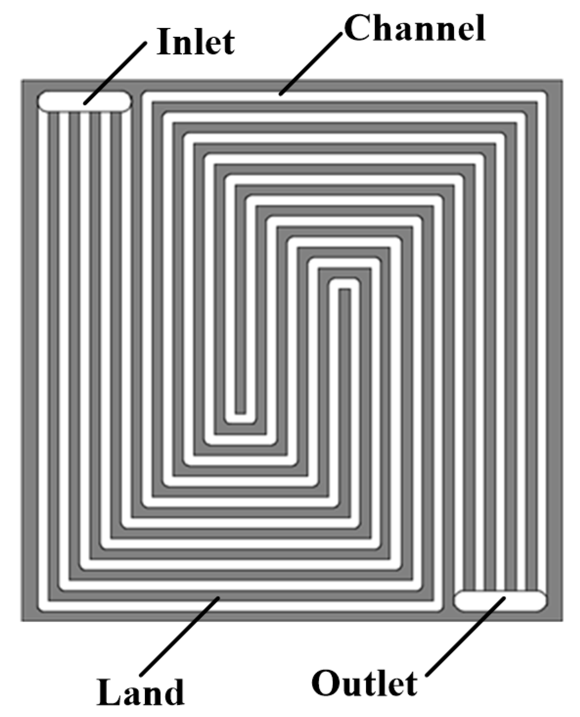
The schematic diagram of the experimental platform is shown in Figure 1. During the experiments, the polarization curve was tested by a G20 Greenlight Innovation fuel cell test station, which was used to control and monitor the electronic load (EE30180A; accuracy: ±1 mV), flow rate (Alicat mass flow controller; accuracy: 0.8% of reading), temperature, RH and gas pressure (accuracy: ±0.1 kPa). The impedance spectra were evaluated by the electrochemical workstation (Gamry Interface 5000E). All measurements were carried out in the galvanostatic mode with the frequency range 500 mHz–100 kHz during the test. The alternating current amplitude was set to 10% of the tested direct current value. The flow field of the single PEMFC used in this paper with 25 cm2 active area is shown in Figure 2; the channel height and channel width were both 1 mm. Besides, to reduce the experimental error and ensure reproducibility, some measures were taken during the test. The PEMFC with virginal MEA was preconditioned by operating with H2 (RH: 100%; flow rate: 400 mL/min) and air (RH: 100%; flow rate: 1200 mL/min) at 75 °C for 5 h. Two heating rods were placed in the anode and cathode endplates, respectively, and every flow field plate had a thermocouple to monitor the operating temperature. Several electric heating tapes between the humidifier and PEMFC were used to prevent any water vapor condensation. After changing the operating parameters (such as inlet RH, inlet pressure and operating temperature), they were kept for several minutes until reaching a steady-state reading. Additionally, before recording the output voltages under specific operating conditions, both sides of the PEMFC were purged with N2 (flow rate: 2000 mL/min; purge duration: 2 min) to remove water droplets and/or film in the flow channels. It is worth mentioning here that all experiments were conducted three times so as to ensure experimental reproducibility. The specifications of the components and operating conditions are listed in Table 1 and Table 2, respectively.
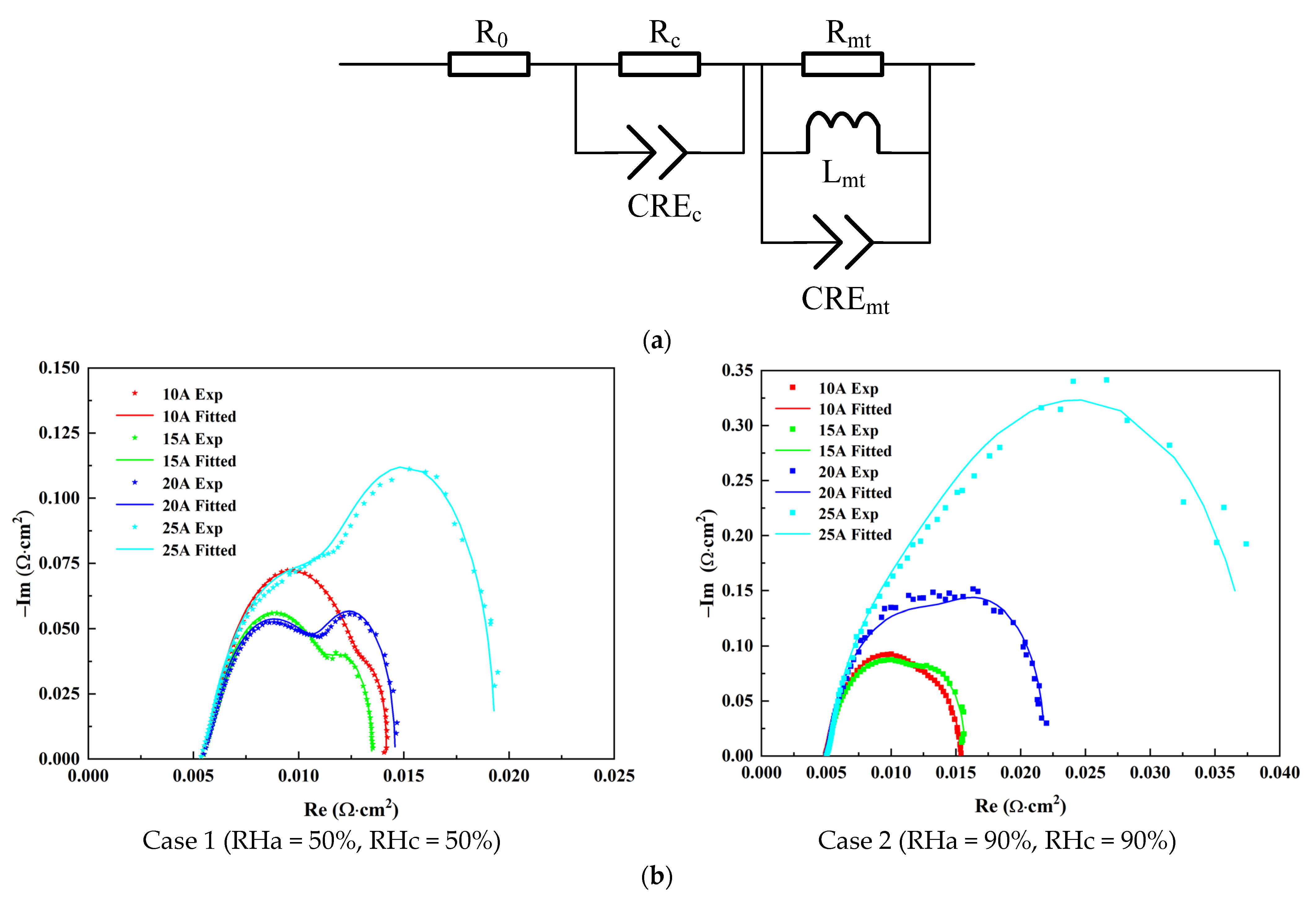
In order to analyze the ohmic resistance and mass transfer resistance, an equivalent circuit model shown in Figure 3a was applied to fit the experimental impedance spectra. In this model, polarization loss at the anode is neglected and R0 denotes the ohmic resistance, which is the conductance of protons. The parallel connection of Rc//CPEc reflects the medium-frequency arc. Besides, the parallel connection of Cmt//Rmt//Lmt is employed to investigate the mass transfer in PEMFC under a state of water flooding, and Rmt denotes the mass transport resistance due to oxygen diffusion in the cathode catalyst layer. The AC impedance spectrum and its fitted curves from 10 to 25 A are shown in Figure 3b. Each Nyquist plot exhibits either one capacitive loop or two distinguishable capacitive loops. The experimental results are in good agreement with the fitted data, and the chi-squared value is less than 0.001.

3. Results and Discussion

3.1. Effect of Anode Inlet RH

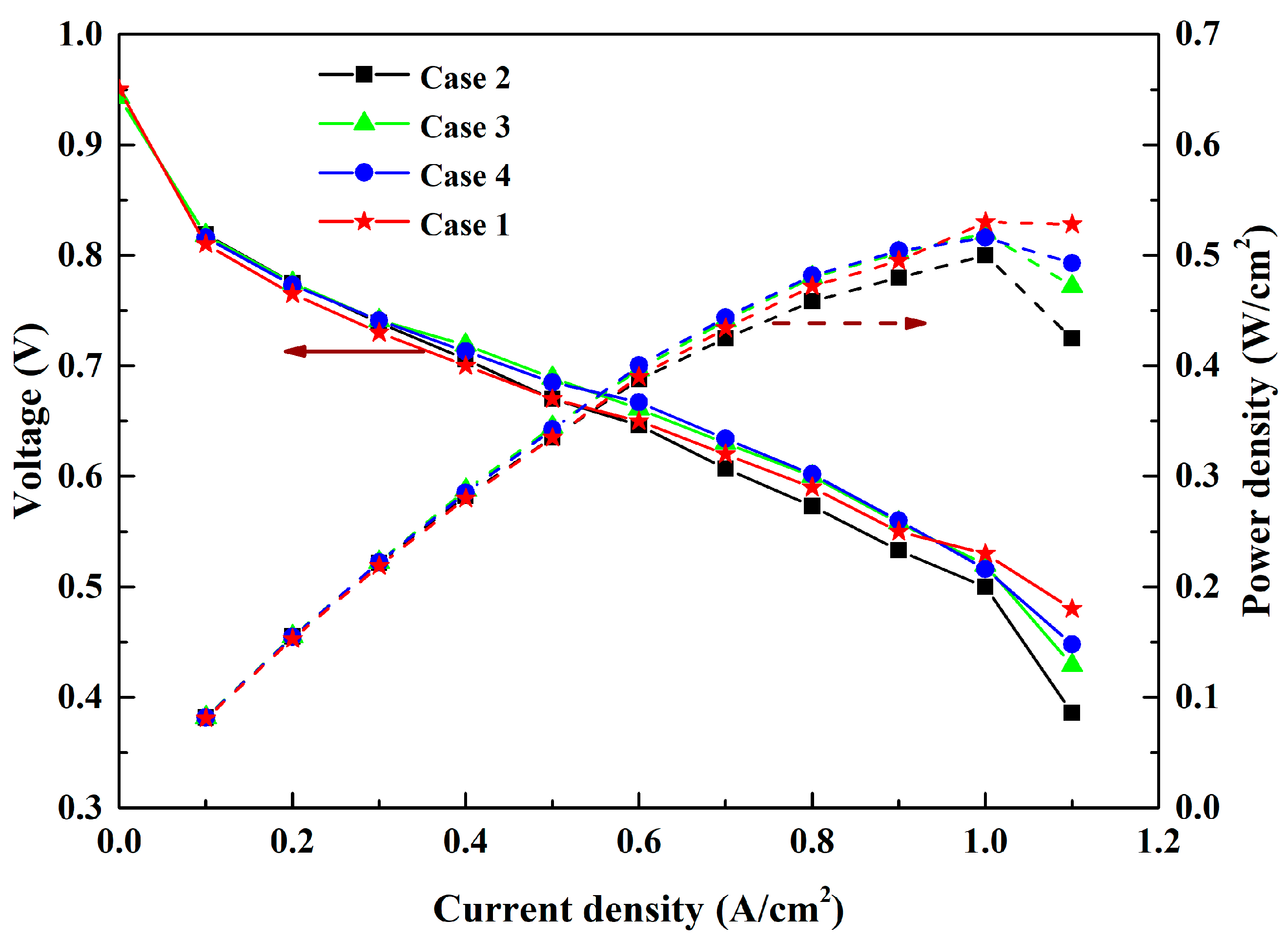
The impacts of anode inlet RH on the output performance of the PEMFC were investigated firstly. In the experiments, the RHa was changed from 50 to 90%, and the RHc was kept at 90%. The polarization curve and power density are shown in Figure 4. When the current density is less than 0.4 A/cm2, the output voltages are approximately equal to each other. However, the performance of case 2 (RHa90%/RHc90%) is distinctly worse than that of case 3 (RHa70%/RHc90%) and case 4 (RHa50%/RHc90%) with the increasing of the current density. At 1.1 A/cm2, which is close to the limiting current density of case 2, the voltage is only 0.386 V and is lower than that of case 3 (0.429 V) and case 4 (0.448 V). This is better represented by the power density curves. In the high current density and high RH case, the PEMFC has more difficulty removing water. As a result, it is more vulnerable to water flooding and leads to higher concentration polarization, which is shown by the mass transfer resistance in the next section. In addition, the high temperature and high RH can cause oxygen partial pressure reduction. Therefore, the voltage of case 2 becomes the smallest. It is important to select reasonable operating conditions for the PEMFC to keep the performance at its best point.
It is worth pointing out that the output voltage and power density are almost the same in case 3 and case 4, while the latter starts becoming higher than the former at more than 1.1 A/cm2. This is conducive to curing the membrane dehydration due to the electro-osmosis drag and to avoid exacerbating concentration polarization in the range of RHa from 50 to 70%. To show the effect of lower RH on the output performance, a dry case (case 1: RHa50%/RHc50%) was selected to compare with the above three cases. In the range from 0.6 to 0.9 A/cm2, the voltage of case 1 becomes higher than that of case 2 and comes close to those of case 3 and case 4. When the current density reaches 1.0 A/cm2, the values of case 1 exceed those of the other three cases. Obviously, the PEMFC working at the low RH conditions would have been suited to the high current density due to increased water generation.
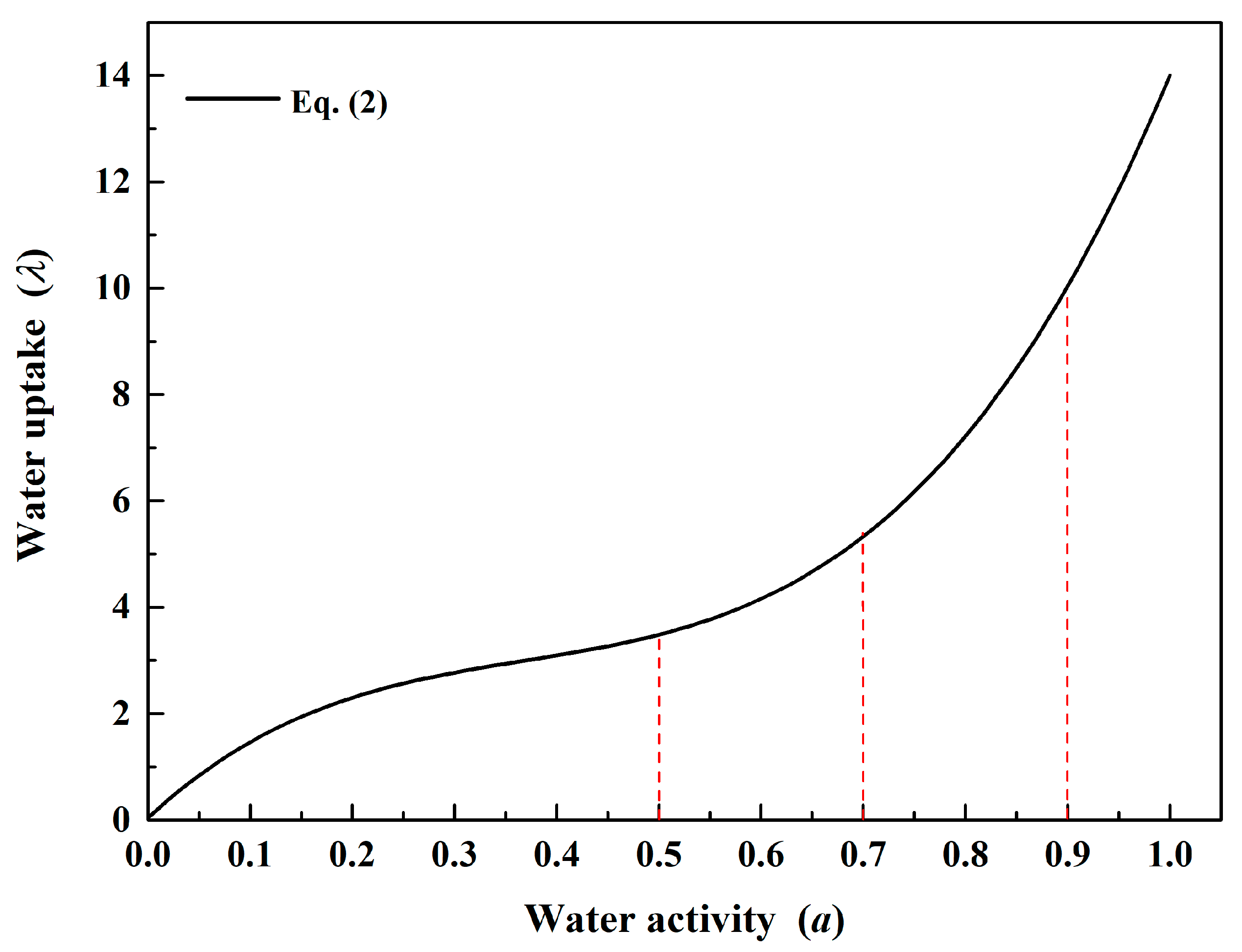
In order to explain the relation between the change in gas RH and the polarization curve, the ohmic resistance and mass transfer resistance were determined by the impedance spectra and equivalent electric circuit. According to Springer’s works [21], the proton conductivity of the membrane, κe, is correlated with the water uptake (λ) and temperature (T) by Equation (1), and Equation (2) shows the water uptake as a function of the membrane water activity (a). At a steady state, the membrane water activity is equal to the local RH value near the membrane. Figure 5 displays the relation between water uptake and membrane water activity.
K e = ( 0.5139 λ 0.326 ) × e [ 1268 × ( 1 303 1 T + 273 ) ]
λ = 0.043 + 17.81 α 39.85 a 2 + 36.0 a 3   0 < a < 1.0
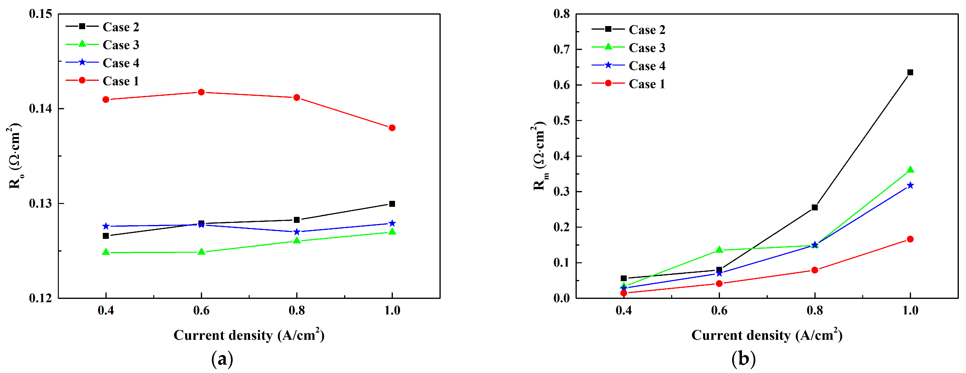
The ohmic resistance and mass transfer resistance are depicted in Figure 6. As for case 1, because the RH is only 50%, as can be seen in Figure 5, little water is absorbed by the membrane. Hence, its ohmic resistance can reach about 0.14 Ω·cm2, which is greater than that of the other cases (<0.13 Ω·cm2) within the current densities in Figure 6a. When the generated water is sufficient to keep membrane hydration at a higher current density (over 1.0 A/cm2), the ohmic resistance of case 1 in turn decreases. However, the low RH case has more advantages in avoiding water flooding in the PEMFC, causing the smallest mass transfer resistance. This is the reason that case 1 has a better performance than the other three cases at 1.0 A/cm2. Besides, the ohmic resistances in cases 2–4 keep rising gradually with the increase in current density. The augmentation of the working load not only produces much more water, but also relieves more heat, which tends to result in increases in the local temperature at the membrane, and this further results in decreases in the local RH and water activity of the membrane [9]. Hence, the ohmic resistances of case 2 are slightly higher than the values in case 3 and case 4, due to the comprehensive effects from local temperature and water activity. As depicted by Equation (1), the proton conduction capacity of the membrane is directly related to the RH and temperature. It is also interesting that excess water due to the increasing current density would accumulate in the GDL and CL, especially at higher RH conditions. It may hinder the gas transfer to the reaction point and lead to a larger concentration loss. Thus, the mass transfer resistance in case 2 increases dramatically to 0.75 Ω·cm2 at 1.0 A/cm2, leading to a sharp decline in the voltage of case 2 at a high current load, as shown in Figure 4.

3.2. Effect of Cathode Inlet RH

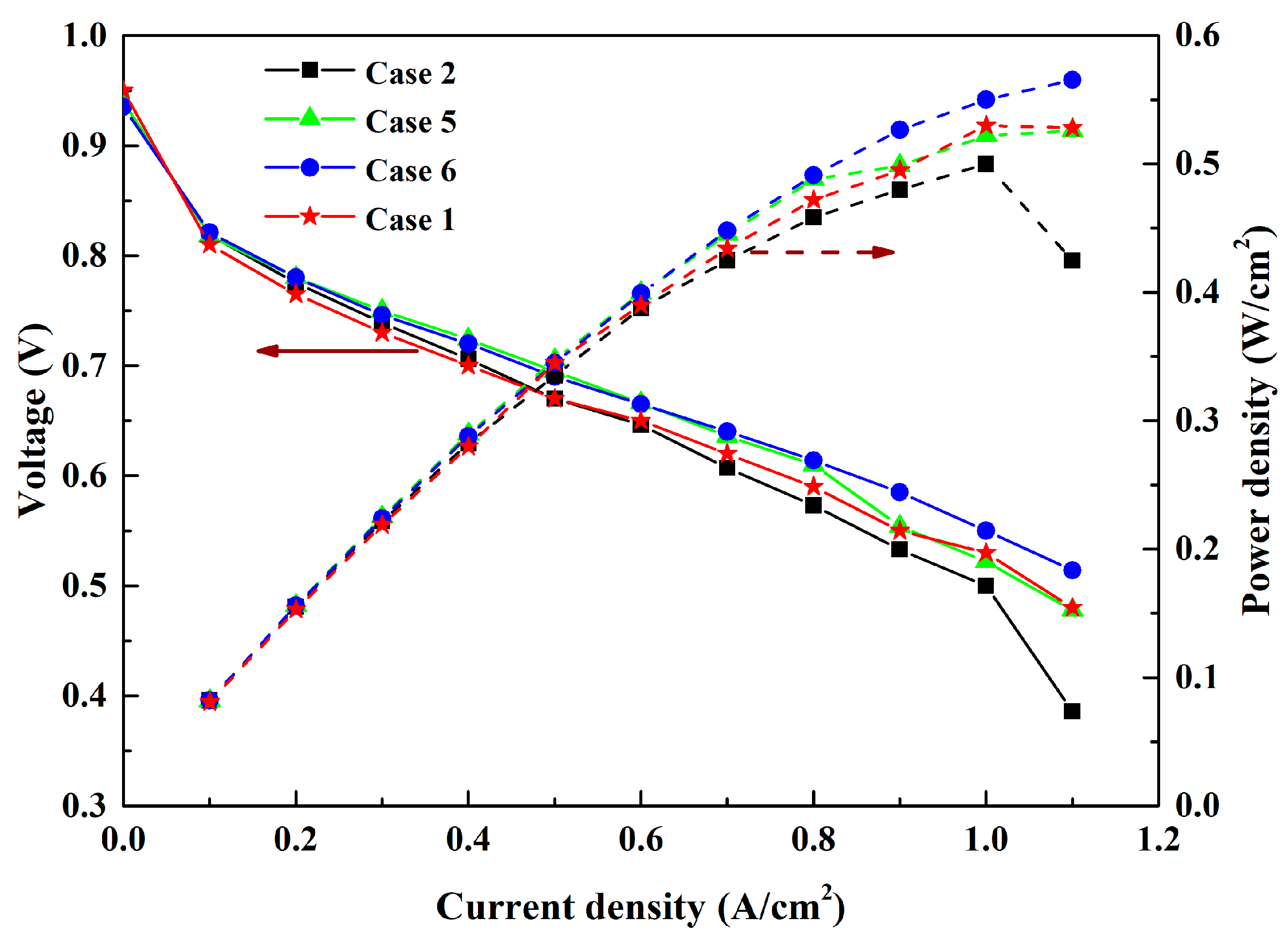
The cathode CL is the place where water is produced, and the inlet RHc has a direct impact on the water flooding and output performance. The results from the different RHc cases are shown in Figure 7. It is evident that case 5 and case 6 have similar change tendencies to case 3 and case 4 at the low and moderate current densities (≤0.8 A/cm2). Interestingly, the power density in case 6 is the highest, increasing to 0.57 W/cm2, and it is slightly greater than the maximum power density of case 5 (0.53 W/cm2) and 0.08 W/cm2 greater than that of case 2 (0.49 W/cm2). Since the RH of the cathode is directly related to the water accumulation in the cathode, it would be difficult for case 6, which has the lower cathode RH (RHc50%), to encounter water flooding along with the growth of the current. This is significantly different from the variation between case 3 and case 4 in Figure 4, and the effect on the output performance resulting from the changes in RHa is less remarkable than the impact from the variation in RHc.
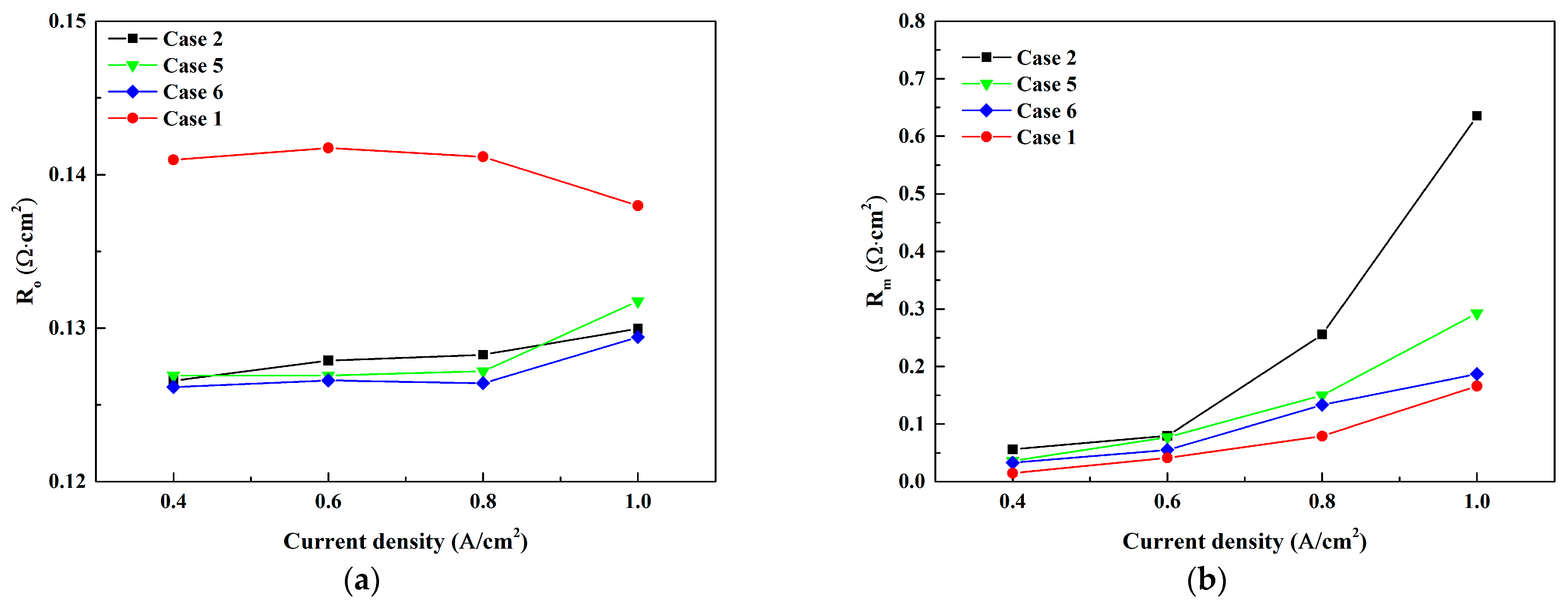
Case 1 (dry case) is also shown in Figure 7 to compare with other cases. The difference from Figure 4 is that case 1 and case 5 present approximately equal performance at high current density (≥1.0 A/cm2), and the former does not reach the top point in Figure 7. Furthermore, Figure 8 shows the ohmic resistance and mass transfer resistance in the above four cases as a function of current density. Similarly, it can be seen that the maximum ohmic resistance and minimum mass transfer resistance are in case 1 for all current densities, while the ohmic resistances of the other three cases raise gradually with current density. This is attributed to the local temperature and RH in the membrane. Besides, the enhancement of the current density causes the mass transfer resistance to rise, since the cathode CL is able to produce more water and the RHc is directly related to the water flooding.

3.3. Effect of RH on the Efficiency

To obtain a full understanding of the effect of RH on fuel utilization, the PEMFC efficiency, η, is regarded as an evaluation index by considering the power consumed by compressed air, which is shown as follows:
η = P W air Q h 2 = I × V W a i r n h 2 × L H V h 2
W a i r = m a i r × c p × T η c o m p [ ( p i n p ) γ 1 γ 1 ]
In Equation (3), P, I and V are output power (W), current load (A) and output voltage (V), respectively. nh2 is the mole flow rate of hydrogen (mol/min) and LHVh2 is the lower heating value of hydrogen, which is specified as 241.83 kJ/mol. The hydrogen flow rate is set as 300 mL/min, and thus the chemical energy of hydrogen Qh2 is equal to about 54 W. Wair is the power consumed by compressed air and mair represents the air mass flow rate. cp and γ are the air specific heat (1.005 kJ/kg/K) and specific heat ratio (1.40), respectively. T and P denote ambient temperature (283 K) and ambient pressure (1 atm). ηcomp is set as 0.9.
The PEMFC efficiencies at 0.4, 0.7 and 1.0 A/cm2 are given in Figure 9, for various RH cases. It becomes evident that an increase in the current density results in the apparent growth of the PEMFC efficiency. This value at 0.7 A/cm2 is almost twice as large as that with at 0.4 A/cm2. At low working current, the variations in the RH have little influence on the PEMFC efficiency, which is about 13.0% at 0.4 A/cm2. There is a considerable change in the same case when the current density is increased to 0.7 A/cm2, and the increment becomes reduced gradually from 0.7 to 1.0 A/cm2. This is because a large quantity of generated water at 1.0 A/cm2 is the main factor hindering the gas diffusion and slowing the electrochemical reaction rate. The diminished increase in the output voltage leads to the increment in the PEMFC efficiency being reduced. At this current density, the PEMFC efficiency in case 6 can reach the highest value, 24.4%, but the data in case 1 and case 2 are both lower than 23%.
Linking to the above polarization curve and impedance spectra, case 6 (RHa90%/RHc50%) has the largest efficiency and optimal performance. On one hand, higher anode RH has the capacity to satisfy the demand in water supply due to the electro-osmosis drag, ensuring membrane hydration at the anode. On the other hand, lower cathode RH facilitates higher oxygen partial pressure at high working temperature compared with higher RHc cases, and it can also relieve the water flooding at high current load. Hence, it is necessary to control the inlet RH at the anode and cathode simultaneously to realize the optimal output performance at elevated operating temperature.
Actually, aside from the effects of inlet gas RH at the anode and cathode, the operating pressure, reaction gas flow rate, flow field structure and material characteristics of GDL and catalyst layer can have a joint influence on the performance and durability of a PEMFC [22,23,24,25]. There have been some studies involving the impacts of multiple variables on PEMFCs or other applications, such as batteries [26,27,28,29]. The multivariate methods employed in these studies offer useful references for us to study the effects of the relevant variables and their interactions on the performance of a PEMFC at 90 °C in our further research, which can provide a more comprehensive understanding of the operation and material design of PEMFCs.

4. Conclusions

In this study, the performance characteristics of a single PEMFC with a rotating serpentine flow field were investigated through an experimental method. The effects of the RH at anode and cathode, which are important for a PEMFC, were analyzed and compared at 90 °C. The main conclusions obtained from this study are summarized as follows:
(1) When the PEMFC operates at 90 °C and high RH (RHa90%/RHc90%), it has the lowest output performance. Lower RH is better for operation at high current density. Besides, the effect resulting from the variations of cathode RH on the output performance is superior to the impact from the variation in anode RH.
(2) Within the current densities, the dry case (RHa50%/RHc50%) has the largest ohmic resistance and smallest mass transfer resistance. Instead, the lowest ohmic resistance and highest mass transfer resistance are obtained for the wet case (RHa90%/RHc90%).
(3) Under the same hydrogen flow rate, the maximum power density, 0.57 W/cm2, and PEMFC efficiency, 24.4%, are obtained when the anode RH is 90% and cathode RH is 50%. Considering that the PEMFC may operate at high temperatures, the inlet RH should be controlled reasonably to reach good performance.

Author Contributions

Conceptualization, Y.X.; methodology, Y.X.; formal analysis, Y.X. and J.Z.; investigation, Y.X. and J.Z.; resources, S.X.; data curation, Y.X. and Y.L.; writing—original draft preparation, Y.X.; writing—review and editing, Y.X. and G.C.; supervision, G.C.; project administration, G.C.; funding acquisition, G.C. and S.X. All authors have read and agreed to the published version of the manuscript.

Funding

This research was funded by the Project of National Major Scientific Instrument and Equipment Development of China, grant number 2012YQ150256.

Conflicts of Interest

The authors declare no conflict of interest.

References

  1. Tran, M.; Bhatti, A.; Vrolyk, R.; Wong, D.; Panchal, S.; Fowler, M.; Fraser, R. A Review of Range Extenders in Battery Electric Vehicles: Current Progress and Future Perspectives. World Electr. Veh. J. 2021, 12, 54. [Google Scholar] [CrossRef]
  2. Tanc, B.; Arat, H.T.; Baltacioglu, E.; Aydin, K. Overview of the next quarter century vision of hydrogen fuel cell electric vehicles. Int. J. Hydrogen Energy 2019, 44, 10120–10128. [Google Scholar] [CrossRef]
  3. New Energy and Industrial Technology Development Organization (NEDO). Road Map 2010 of NEDO Fuel Cell and Hydrogen Technology Development. Department of Fuel Cell and Hydrogen Technology, 2010. Available online: http://www.nedo.go.jp/content/100642949.pdf (accessed on 30 June 2010).
  4. Atiyeh, H.K.; Karan, K.; Peppley, B.; Phoenix, A.; Halliop, E.; Pharoah, J. Experimental investigation of the role of a microporous layer on the water transport and performance of a PEM fuel cell. J. Power Sources 2007, 170, 111–121. [Google Scholar] [CrossRef]
  5. Li, H.; Tang, Y.H.; Wang, Z.W.; Shi, Z.; Wu, S.; Song, D.; Zhang, J.; Fatih, K.; Zhang, J.; Wang, H.; et al. A review of water flooding issues in the proton exchange membrane fuel cell. J. Power Sources 2008, 178, 103–117. [Google Scholar] [CrossRef]
  6. Judith, O.; Manikandan, R.; Murat, A. In situ detection of anode flooding of a PEM fuel cell. Int. J. Hydrogen Energy 2009, 34, 6765–6770. [Google Scholar]
  7. Ozen, D.N.; Timurkutluk, B.; Altinisik, K. Effects of operation temperature and reactant gas humidity levels on performance of PEM fuel cells. Renew. Sustain. Energy Rev. 2016, 59, 1298–1306. [Google Scholar] [CrossRef]
  8. Zhang, Q.; Lin, R.; Técher, L.; Cui, X. Experimental study of variable operating parameters effects on overall PEMFC performance and spatial performance distribution. Energy 2016, 115, 550–560. [Google Scholar] [CrossRef]
  9. Ge, N.; Banerjee, R.; Muirhead, D.; Lee, J.; Liu, H.; Shrestha, P.; Wong, A.; Jankovic, J.; Tam, M.; Susac, D.; et al. Membrane dehydration with increasing current density at high inlet gas relative humidity in polymer electrolyte membrane fuel cells. J. Power Sources 2019, 422, 163–174. [Google Scholar] [CrossRef]
  10. Janicka, E.; Mielniczek, M.; Gawel, L.; Darowicki, K.; Landowska, P. The impact of air humidity on the operation of proton exchange membrane fuel cells determined using dynamic electrochemical impedance spectroscopy. Electrochim. Acta 2020, 341, 136036. [Google Scholar] [CrossRef]
  11. Mohsin, M.; Raza, R.; Mohsin-ul-Mulk, M.; Yousaf, A.; Yousaf, A.; Hacker, V. Electrochemical characterization of polymer electrolyte membrane fuel cells and polarization curve analysis. Int. J. Hydrogen Energy 2020, 45, 24093–24107. [Google Scholar] [CrossRef]
  12. Ou, K.; Yuan, W.; Choi, M.; Yang, S.; Kim, Y. Performance increase for an open-cathode PEM fuel cell with humidity and temperature control. Int. J. Hydrogen Energy 2017, 42, 1–11. [Google Scholar] [CrossRef]
  13. Askaripour, H. Effect of operating conditions on the performance of a PEM fuel cell. Int. J. Heat Mass Transf. 2019, 144, 118705. [Google Scholar] [CrossRef]
  14. Chen, H.; Liu, B.; Zhang, T.; Pei, P. Influencing sensitivities of critical operating parameters on PEMFC output performance and gas distribution quality under different electrical load conditions. Appl. Energy 2019, 255, 113849. [Google Scholar] [CrossRef]
  15. Xing, L.; Cai, Q.; Xu, C.; Liu, C.; Scott, K.; Yan, Y. Numerical study of the effect of relative humidity and stoichiometric flow ratio on PEM (proton exchange membrane) fuel cell performance with various channel lengths: An anode partial flooding modelling. Energy 2016, 106, 631–645. [Google Scholar] [CrossRef]
  16. Nishimura, A.; Kamiya, S.; Okado, T.; Sato, Y.; Hirota, M.; Kolhe, M.L. Heat and mass transfer analysis in single cell of PEFC using different PEM and GDL at higher temperature. Int. J. Hydrogen Energy 2019, 44, 29631–29640. [Google Scholar] [CrossRef]
  17. Nishimura, A.; Yoshimura, M.; Kamiya, S.; Hirota, M.; Hu, E. Impact of Relative Humidity of Supply Gas on Temperature Distributions in Single Cell of Polymer Electrolyte Fuel Cell When Operated at High Temperature. J. Energy Power Eng. 2017, 11, 706–718. [Google Scholar] [CrossRef] [Green Version]
  18. Akitomo, F.; Sasabe, T.; Yoshida, T.; Naito, H.; Kawamura, K.; Hirai, S. Investigation of effects of high temperature and pressure on a polymer electrolyte fuel cell with polarization analysis and X-ray imaging of liquid water. J. Power Sources 2019, 431, 205–209. [Google Scholar] [CrossRef]
  19. Jeon, S.W.; Cha, D.; Kim, H.S.; Kim, Y. Analysis of the system efficiency of an intermediate temperature proton exchange membrane fuel cell at elevated temperature and relative humidity conditions. Appl. Energy 2016, 166, 165–173. [Google Scholar] [CrossRef]
  20. Chang, Y.; Qin, Y.; Yin, Y.; Zhang, J.; Li, X. Humidification strategy for polymer electrolyte membrane fuel cells—A review. Appl. Energy 2018, 230, 643–662. [Google Scholar] [CrossRef]
  21. Springer, T.E.; Zawodzinski, T.A.; Gottesfeld, S. Polymer electrolyte fuel cell model. J. Electrochem. Soc. 1991, 138, 2334–2342. [Google Scholar] [CrossRef]
  22. Yoshiyuki, H.; Hiroshi, D.; Tomoaki, N. Effects of environmental conditions on cathode degradation of polymer electrolyte fuel cell during potential cycle. World Electr. Veh. J. 2019, 10, 24. [Google Scholar]
  23. Yuan, X.Z.; Li, H.; Gu, E.; Qian, W.; Girard, F.; Wang, Q.; Biggs, T.; Jaeggle, M. Measurements of GDL Properties for Quality Control in Fuel Cell Mass Production Line. World Electr. Veh. J. 2016, 8, 422–430. [Google Scholar] [CrossRef] [Green Version]
  24. Chuang, P.A.; Rahman, M.A.; Mojica, F.; Hussey, D.S.; Jacobson, D.L.; Lamanna, J.M. The interactive effect of heat and mass transport on water condensation in the gas diffusion layer of a proton exchange membrane fuel cell. J. Power Sources 2020, 480, 229121. [Google Scholar] [CrossRef]
  25. Hosseini, M.; Afrouzi, H.H.; Arasteh, H.; Toghraie, D. Energy analysis of a proton exchange membrane fuel cell (PEMFC) with an open-ended anode using agglomerate model: A CFD study. Energy 2019, 188, 116090. [Google Scholar] [CrossRef]
  26. Moein-Jahromi, M.; Kermani, M.J. Three-dimensional multiphase simulation and multi-objective optimization of PEM fuel cells degradation under automotive cyclic loads. Energy Convers. Manag. 2021, 231, 113837. [Google Scholar] [CrossRef]
  27. Liu, Z.; Zeng, X.; Ge, Y.; Shen, J.; Liu, W. Multi-objective optimization of operating conditions and channel structure for a proton exchange membrane fuel cell. Int. J. Heat Mass Transf. 2017, 111, 289–298. [Google Scholar] [CrossRef]
  28. Khaki, B.; Das, P. Multi-objective optimal charging current and flow management of Vanadium Redox Flow Batteries for fast charging and energy-efficient operation. J. Power Sources 2021, 506, 230199. [Google Scholar] [CrossRef]
  29. Jiaqiang, E.; Han, D.; Qiu, A.; Zhu, H.; Deng, Y.; Chen, J.; Zhao, X.; Zuo, W.; Wang, H.; Chen, J.; et al. Orthogonal experimental design of liquid-cooling structure on the cooling effect of a liquid-cooled battery thermal management system. Appl. Therm. Eng. 2018, 132, 508–520. [Google Scholar]
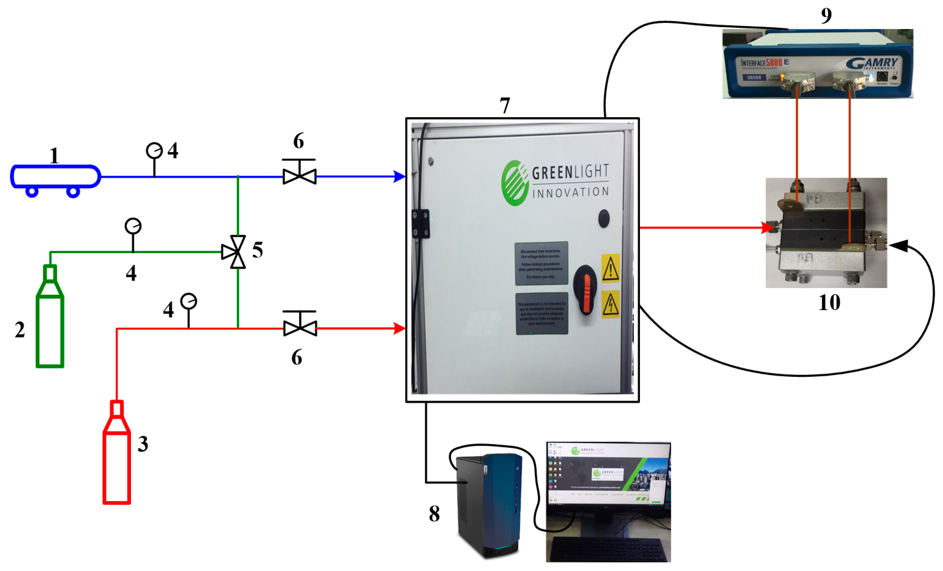
Figure 1. Schematic diagram of the experimental platform (1. air compressor, 2. N2, 3. H2, 4. pressure gauge, 5. triple valve, 6. reducing valve, 7. G20, 8. desktop, 9. electrochemical workstation, 10. PEMFC).
Wevj 12 00110 g001
Figure 2. Flow field of the PEMFC.
Wevj 12 00110 g002
Figure 3. (a) Equivalent electric circuit. (b) Nyquist plot from the EIS measurements at various currents.
Wevj 12 00110 g003
Figure 4. Polarization curve and power density in various RHa cases.
Wevj 12 00110 g004
Figure 5. Relation between water uptake and membrane water activity.
Wevj 12 00110 g005
Figure 6. (a) Ohmic resistance and (b) mass transfer resistance as a function of current density in various RHa cases.
Wevj 12 00110 g006
Figure 7. Polarization curve and power density in various RHc cases.
Wevj 12 00110 g007
Figure 8. (a) Ohmic resistance and (b) mass transfer resistance as a function of current density in various RHc cases.
Wevj 12 00110 g008
Figure 9. Effects of inlet RH on PEMFC efficiency at various current densities.
Wevj 12 00110 g009
Table 1. Specifications of components of the PEMFC.
PartCharacteristicsSize
MembraneGORE-SELECT 735.185 cm ∗ 5 cm ∗ 18 μm
Catalyst layer (CL)Pt loading
(anode: 0.1 mg/cm2; cathode: 0.35 mg/cm2)
5 cm ∗ 5 cm ∗ 5 μm
Microporous layer (MPL)attached with GDL5 cm ∗ 5 cm ∗ 30 μm
Gas diffusion layer (GDL)SGL 28BC5 cm ∗ 5 cm ∗ 235 μm
Flow field plateCarbon graphite9 cm ∗ 9 cm ∗ 2 cm
Current collectorCopper coated with gold9 cm ∗ 9 cm ∗ 3 mm
EndplateAluminum9 cm ∗ 9 cm ∗ 2 cm
Table 2. Operating conditions during the tests.
Operation ConditionAnodeCathode
Gas type and flow rateHydrogen: 300 mL/minAir: 900 mL/min
Temperature of gas feed90 °C90 °C
Absolute pressure of gas1.5 atm1.5 atm
Relative humidityCase 1 (RHa50%/RHc50%); Case 2 (RHa90%/RHc90%)
Case 3 (RHa70%/RHc90%); Case 4 (RHa50%/RHc90%)
Case 5 (RHa90%/RHc70%); Case 6 (RHa90%/RHc50%)
Publisher’s Note: MDPI stays neutral with regard to jurisdictional claims in published maps and institutional affiliations.