1. Introduction
In 2019, China’s car ownership ranked first in the world and the greenhouse effect, environmental pollution and other problems became apparent. Therefore, in recent years, a new energy industry has been vigorously developed, with electric vehicles foremost [
1]. Because of its small size, high stability, simple structure and high-power density, the permanent magnet synchronous motor has become the main driving force of electric vehicles [
2]. However, traditional PMSM control needs to rely on photoelectric encoders, resolvers, and other components to extract the speed and position information of the motor rotor. These sensors not only increase the economic cost and installation difficulty, but also are susceptible to interference from the external environment causing detection errors, which is related to accidents and affects the safety performance of the vehicle [
3,
4]. Therefore, the research of sensor-less PMSM control strategy is of great significance.
The sensor-less control strategy extracts the PMSM voltage, current, and back-EMF signals, and then estimates the motor’s speed and rotor position information through different mathematical models. There are currently three main estimation methods, which are divided into low-speed, high-speed, and full-speed sections according to the operating speed of the motor [
4]. When the motor rotor speed is low or even zero speed, the back-EMF signal is weak and is accompanied by many interference signals, which are difficult to accurately detect. Then, the speed and position of the motor rotor are generally estimated by using the salient pole characteristics of the motor [
5] and injecting additional high-frequency signals. The commonly used methods include the rotating high frequency voltage injection method [
6,
7], and the pulsed high frequency voltage injection method [
8,
9]. When the motor is running in the high-speed range, the back-EMF signal enhancement and extraction are simple. Then, a control strategy based on a fundamental mathematical model is usually used [
4], which includes the synovial observer algorithm [
10,
11,
12,
13,
14,
15], the model reference adaptive algorithm [
16,
17], the extended Kalman filter algorithm [
18,
19], etc. For observation at full speed, most of the hybrid control strategies are currently used,. combining two different estimation strategies of low-speed section and high-speed section to observe the motor speed and rotor position respectively. For the transition area between low speed and high speed, the linear weighted average algorithm [
20] is employed.
The traditional SMO observer algorithm is robust and insensitive to external disturbances. However, in the traditional SMO algorithm, a sign function as the switching function of the system cause shigh-frequency chattering, and a phase delay occurs due to a low-pass filter with a fixed cut-off frequency to extract the discrete back-EMF signal. This article provides an improved new SMO control strategy by using a sigmoid function to replace the signum function in the traditional SMO in order to reduce the high frequency chattering of the system, and to introduce an adaptive filter instead of a low-pass filter with a fixed cutoff frequency to further eliminate harmonics and chattering. Meanwhile the proposed SMO algorithm adaptively compensates the estimated back EMF and reduces the estimation error caused by the phase delay. Through Matlab/Simulink simulation analysis and experimental verification respectively, it was proved that the improved SMO control strategy can significantly reduce chattering and phase delay, and can maintain good estimation performance at low speeds.
2. Analysis of the SPMSM Sensorless Control System
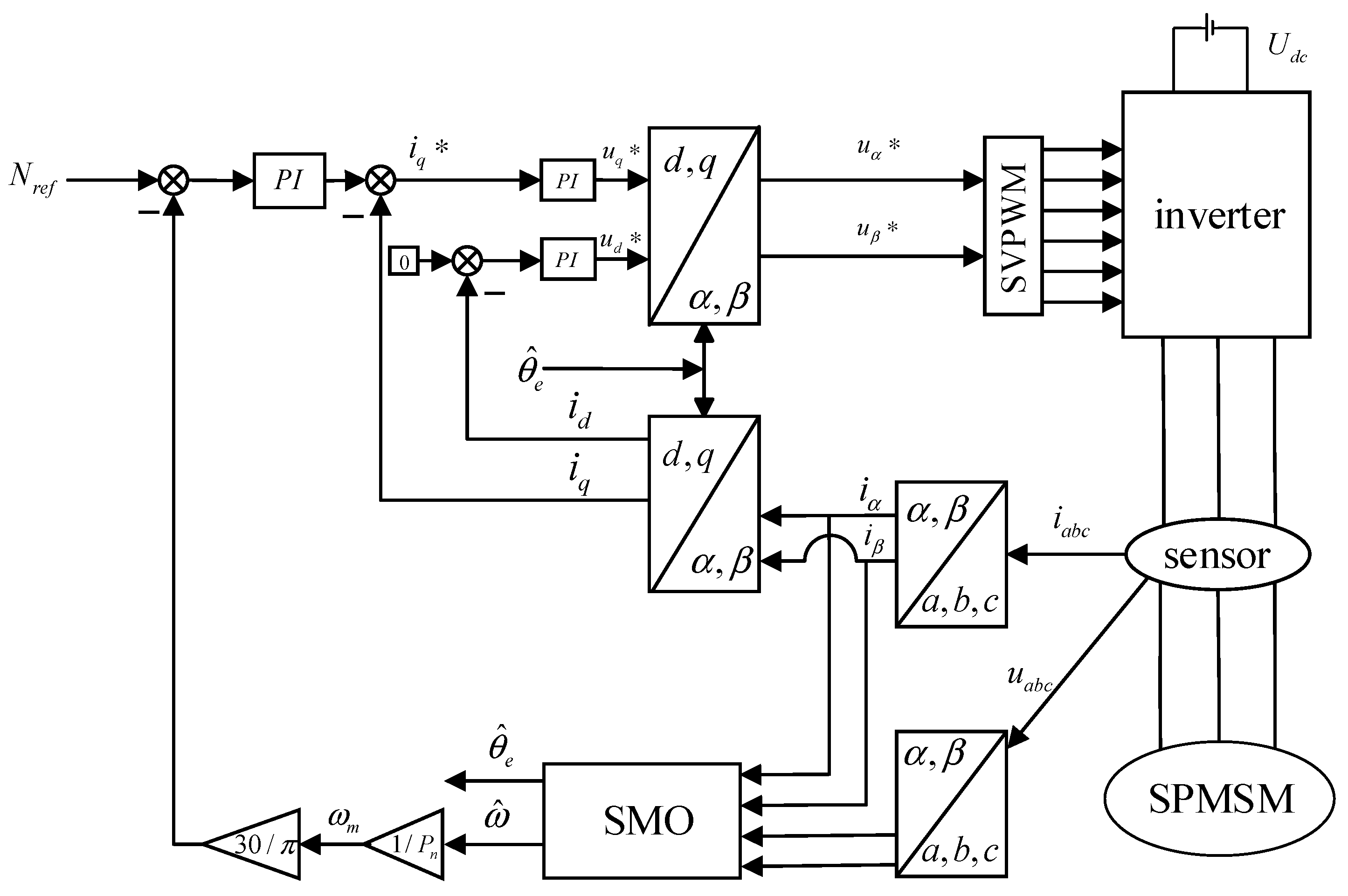
Figure 1 shows a sensorless control block diagram of a surface-mounted permanent magnet synchronous motor based on an improved sliding film observer. The whole system includes SPMSM (surface permanent magnet synchronous motor), a three-phase inverter module, a SVPWM module, a vector control module, and an improved SMO module. The vector controlling method sets
and applies Clark transformation to convert the three-phase current and voltage collected by the sensor into the current component
and voltage component
on the
axis, the current component
and voltage component
on the
axis, in a two-phase stationary coordinate system. Then the
,
,
,
components are the input to the improved SMO module. The motor speed and position information estimated by the improved sliding mode observer module are calibrated through the speed loop PI controller and the current loop controller. The calibrated output is the voltage component
on the d axis and the voltage component
on the q axis in the synchronous rotating coordinate system. Then, the voltage components in the two-phase stationary coordinate system are modulated through the inverter after space vector pulse width modulation SVPWM, and the voltage is converted to three-phase alternating current which is supplied to the motor. Finally, the motor control system forms a closed control loop.
The surface mounted permanent magnet synchronous motor (SPMSM) has the advantages of simple structure, strong anti-interference capability, and manageable control performance and is widely used in systems that require high precision [
21]. Therefore, this article concerns the study of SPMSM. The equation of states of the stationary coordinate system (αβ coordinate system) SPMSM is given below:
where
and
are given by
where
and
are two-phase stator voltages respectively;
and
are two-phase stator currents respectively;
and
are two opposite electromotive forces respectively;
is the stator resistance;
is the rotor position angle;
is the stator inductance;
is the rotor angular velocity;
is the rotor flux.
Given Equation (2), the position and speed of the SPMSM rotor can be derived as:
4. New and Improved SMO Control Strategy
4.1. Improvement of Switching Function
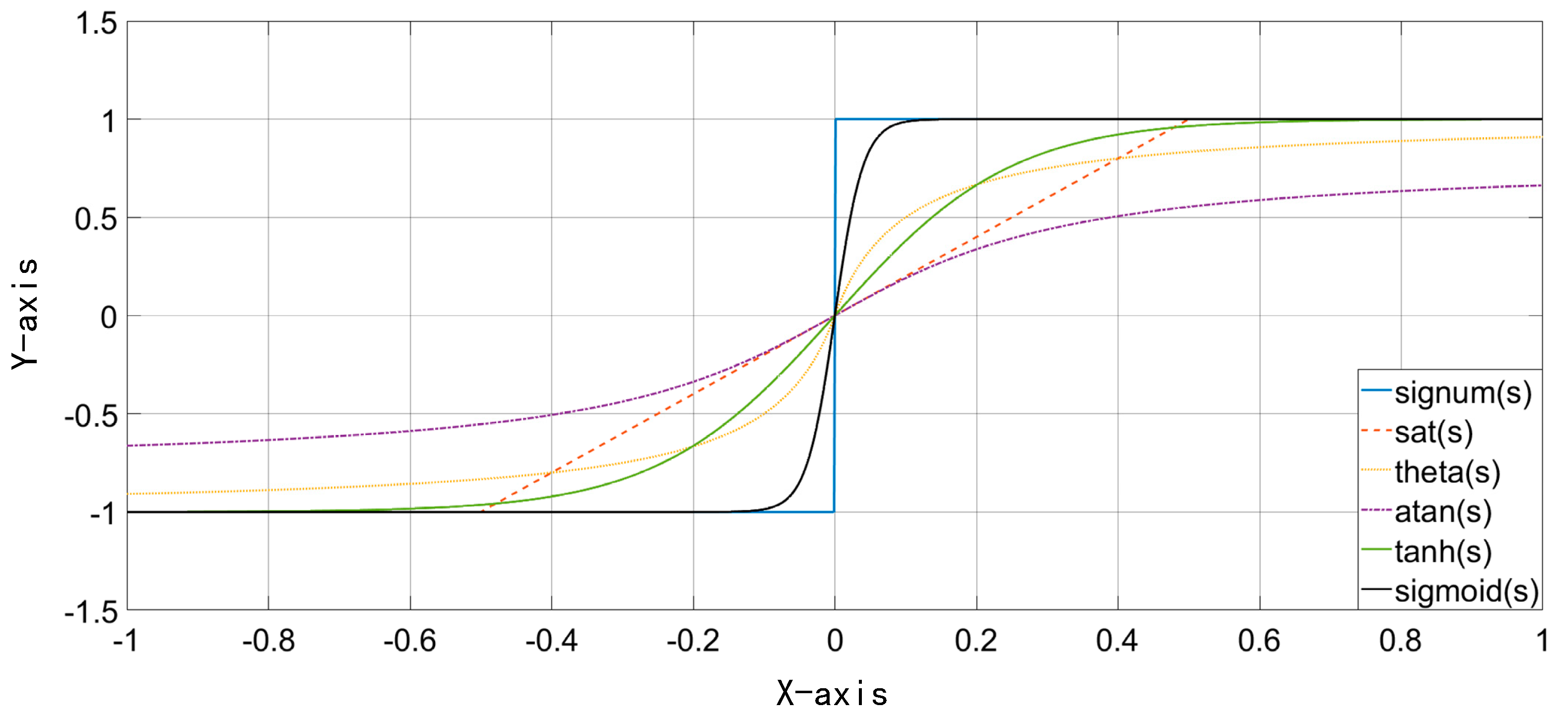
The switching function of the traditional sliding film control strategy is a sign function. The discontinuity of the sign function at the zero-point results in high-frequency chatter in the system. To address this issue, many scholars have aimed to improve it, including the saturation function sat(s), continuous function theta(s), arctangent function atan(s), hyperbolic tangent function tanh(s), sigmoid(s) function to replace the sign function signum(s) in the traditional synovial control strategy. The graphs of various switching functions are shown below.
It can be seen from
Figure 5 that the value of the blue curve (sign function) changes from −1 to 1 at the zero-crossing point. The sudden change of this function makes the whole system appear as high-frequency chattering. To improve this problem, a function that is excessively smoother at the zero point should be selected, while the convergence rate characteristics of the function should also be considered. Based on the above considerations and the results in
Figure 5, this paper utilizes a continuous, smooth and dynamically variable sigmoid(s) to replace the symbolic function in the traditional synovial control strategy.
The sigmoid(s) expression is as follows:
where
is a key factor.
The value of will directly affect the convergence speed of the function. Thus, selecting an appropriate value for can improve the robustness of the system and better reduce the system chattering and phase delay.
The equation for designing improved SMO control is given by
where
is the optimized function gain [
22].
According to Equations (1)–(11), the current error equation of SPMSM of improved SMO control can be given by
The sliding surface is selected as . According to the sliding film structure control strategy, we define as the sliding surface of the system. When the system continuously operates with high frequency and small amplitude on the sliding mode surface, and finally approximately coincides with the sliding mode surface, the value of the estimated current can be regarded as the actual value. The key control factor is the back-EMF signal generated when the system is running.
The Lyapunov criterion is used in the literature [
22], and the stability analysis of the improved SMO control strategy based on the sigmoid function is introduced in detail and will not be mentioned here again.
4.2. Filter Improvements
To obtain the back-EMF signal, traditional methods often use a low-pass filter with a fixed cut-off frequency to extract the estimated value of the back-EMF, and then perform arctangent calculation on the estimated back-EMF to obtain the estimated value of the SPMSM rotor position and speed (Formulas (6)–(9)). However, the accuracy is poor because it cannot perform the appropriate filter adjustments based on changes in the input signal in real time. The extracted signal contains a lot of interference signals, and it is impossible to accurately extract the required back-EMF signal, which leads to problems of high-frequency chattering, phase delay, and observation failure in the low-speed section of traditional SMO. In order to solve the above problems, this paper uses the recursive least-squares (Recursive Least-Squares, RLS) algorithm adaptive filter to replace the low-pass filter in the traditional sliding mode control strategy.
The RLS adaptive filter used in this article requires discrete input signals, so the continuous signal of the improved SMO algorithm should be discretely processed before inputting the RLS adaptive filter.
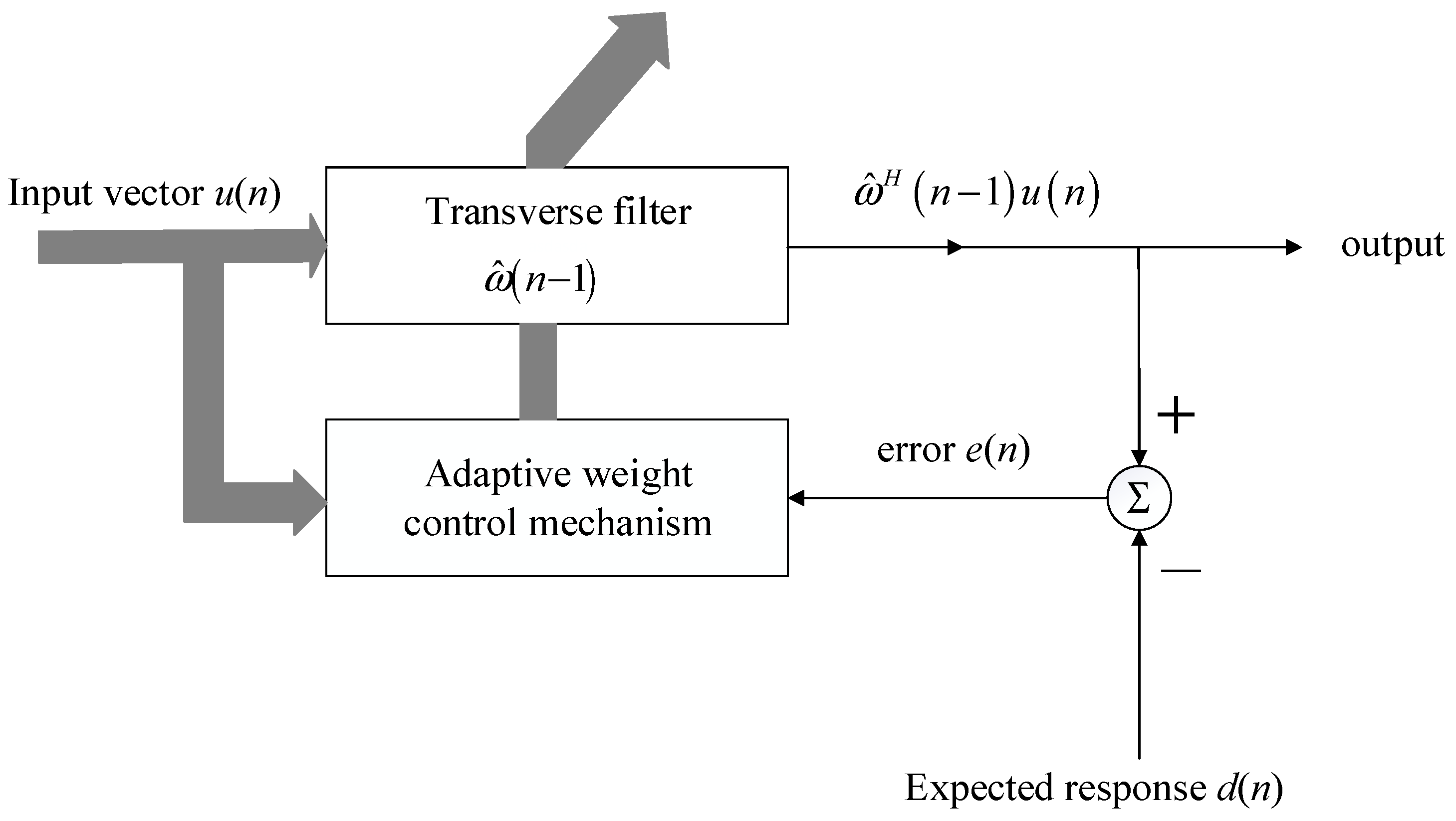
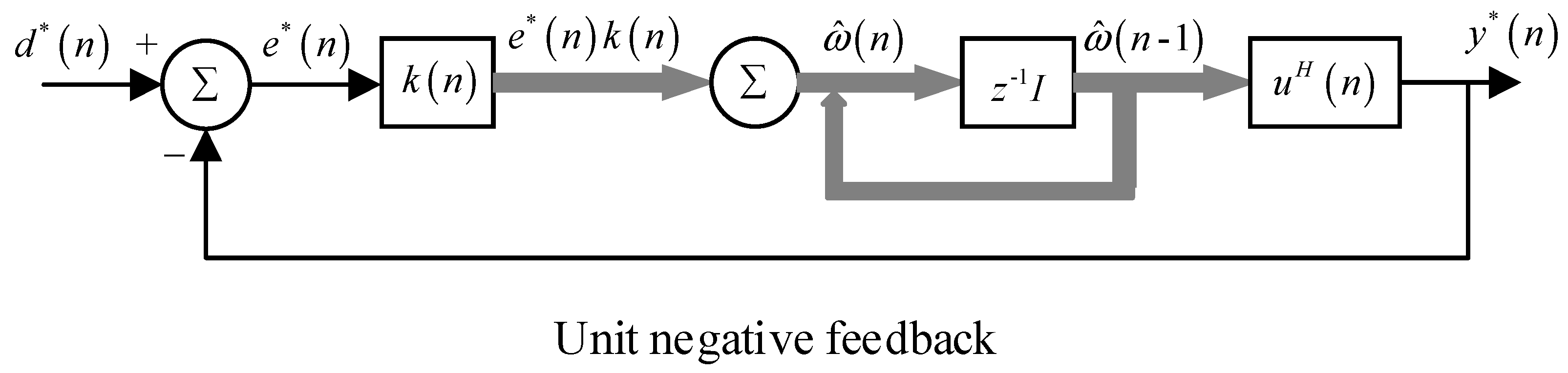
The RLS adaptive filter calculates and updates the weights and coefficients of the FIR (Finite Impulse Response, FIR) filter in real time through the recursive least squares algorithm, and filters the signal of the input filter through an adaptive weight control strategy to get the optimal Waveform. The matrix equation of the RLS adaptive filter is expressed as follows:
where
is the current time index;
is the step n buffer of the vector of input samples;
is the inverse covariance matrix of the nth step;
is the gain vector at step n;
is the vector estimated by the filter tap of the n-th step;
is the filtered output at step n;
is the n-step estimation error;
is the expected response at step n;
is the forgetting factor;
and
correspond to the current error input samples in the SMO;
is the estimated back-EMF output from the RLS adaptive filter, and
is 1.
The algorithm block diagram is shown in
Figure 6, and the signal flow diagram of the RLS adaptive filter is shown in
Figure 7.
Although the RLS adaptive filter has greatly improved all aspects compared with the traditional low-pass filter, it will inevitably bring some phase delay problems. In order to reduce the influence of the phase delay, an angle compensation is added to the estimated value of the rotor position to reduce the error between the estimated value and the actual value. The final estimate of corner
is:
where
is the commonly used coefficient for phase angle compensation of the filter.
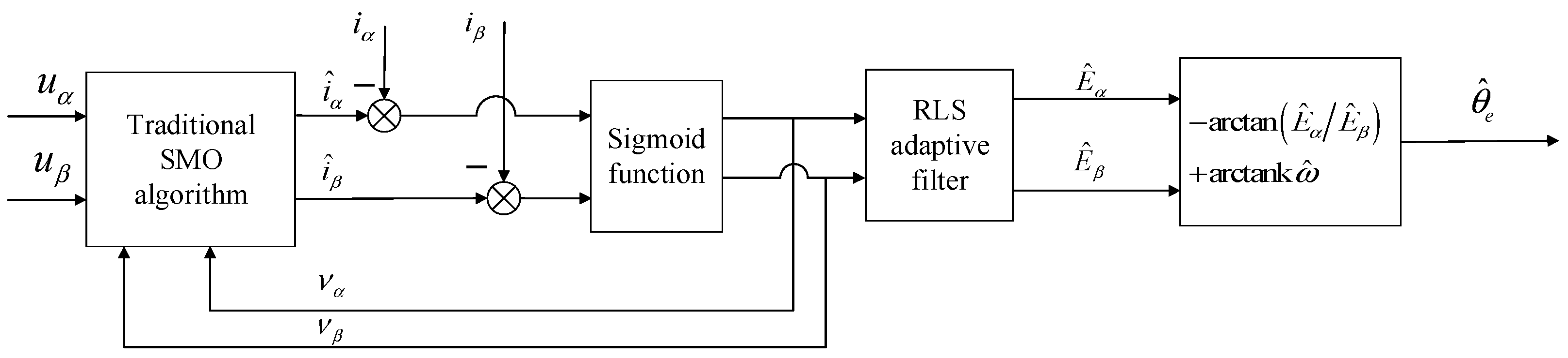
The improved SMO control strategy based on the sigmoid function and the RLS adaptive filter reduces the chattering phenomenon of the switching function in the transition phase compared to the traditional SMO control strategy. Meanwhile, the adaptive filtering method improves the extraction accuracy of the back-EMF signal. The problems such as high-frequency chattering, phase delay, and difficulty in extracting fundamental signals at low speeds have been significantly alleviated. The block diagram of the improved SMO algorithm is shown in
Figure 8.
5. System Simulation Result Analysis
Aiming at the problems of the above-mentioned SMO algorithm, this paper proposes an improved SMO algorithm. The sigmoid function is substituted for the hyperbolic tangent function in the improved SMO algorithm to further reduce the high-frequency chattering phenomenon and increase the convergence rate of the system. Focusing on the problems of phase delay and difficulty in extracting back-EMF signals at low speeds. The low-pass filter with a fixed cutoff frequency used in the improved SMO algorithm and the RLS adaptive filter with variable cut-off frequency replace the traditional low-pass filter.
A simulation model was built in Matlab/Simulink for testing. An improved SMO based on sigmoid(s) function and RLS adaptive filter was established. The simulation model applies a surface-mounted permanent magnet synchronous motor. The specific parameters of the motor are as in
Table 1. The red in the figure below is the estimated curve, and the black is the actual curve. The system simulation time is set to 0.1 s, and the speed is changed abruptly at a certain time in the middle of the system to further verify the stability and tracking performance of the system.
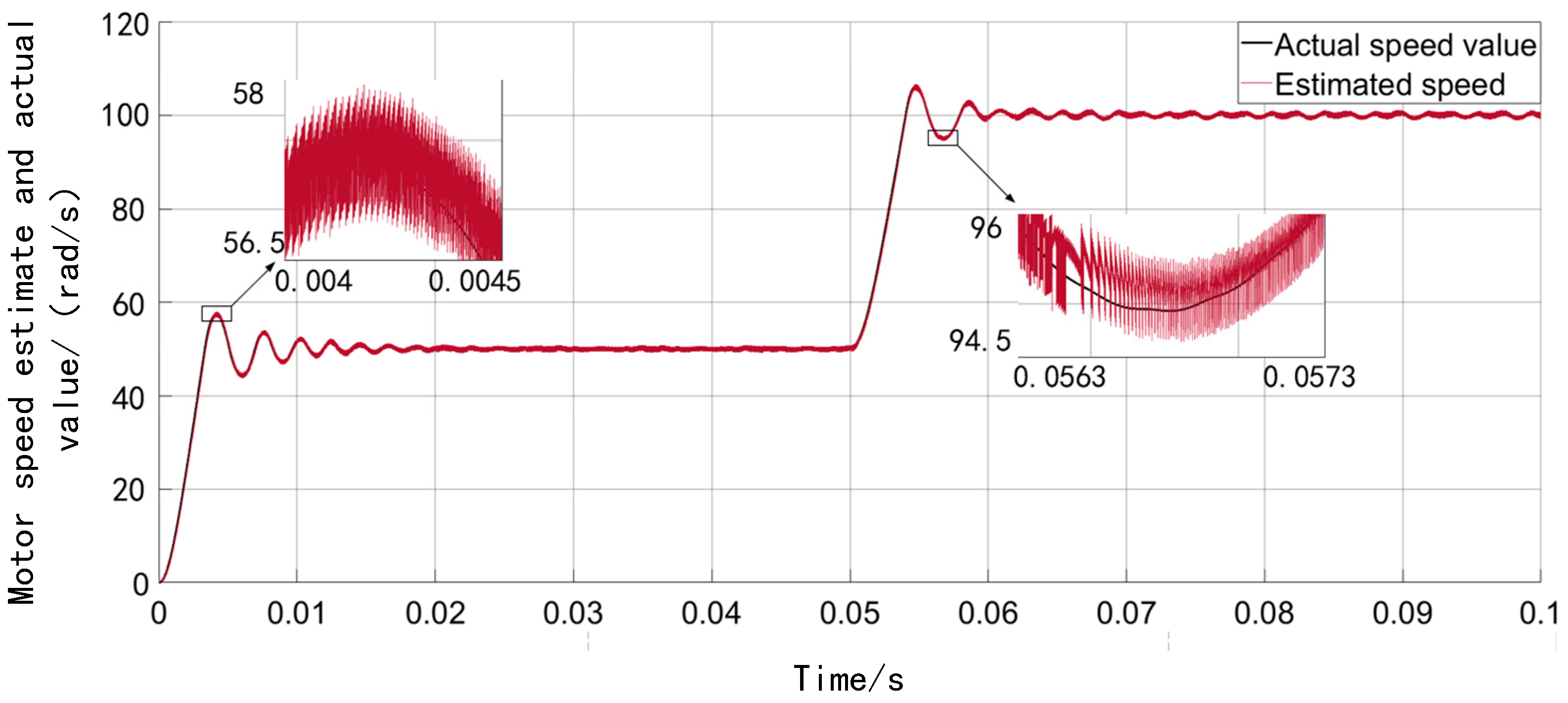
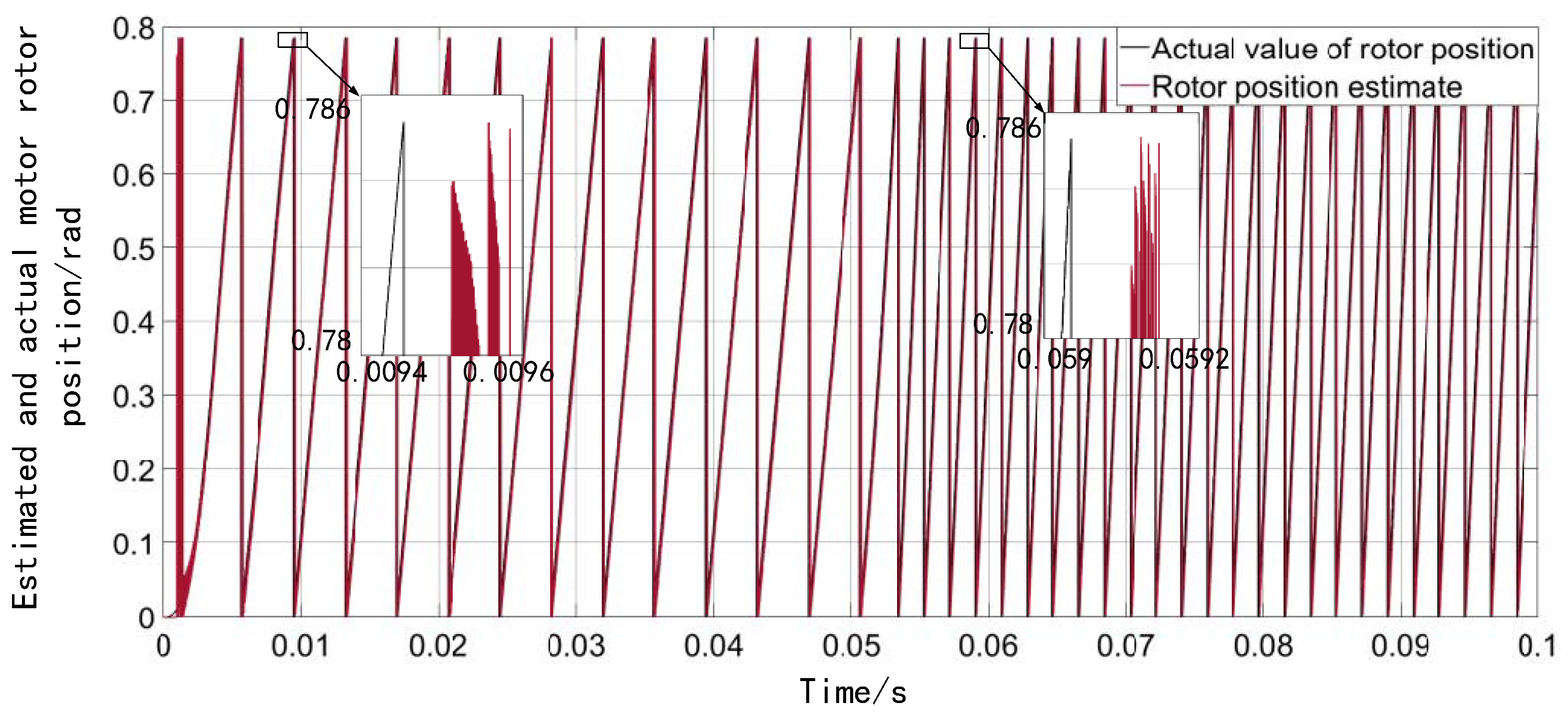
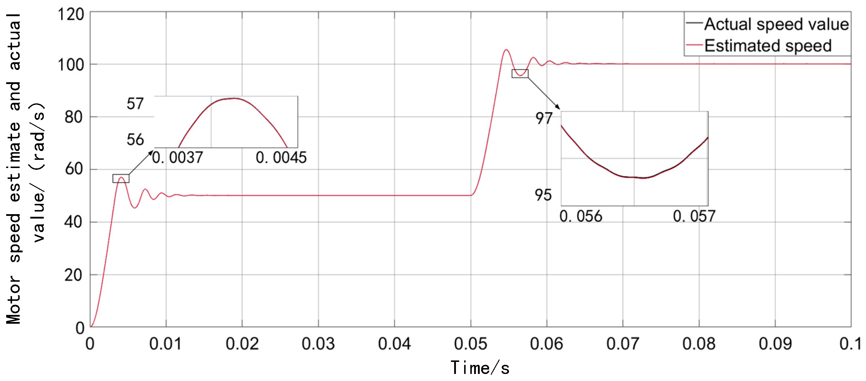
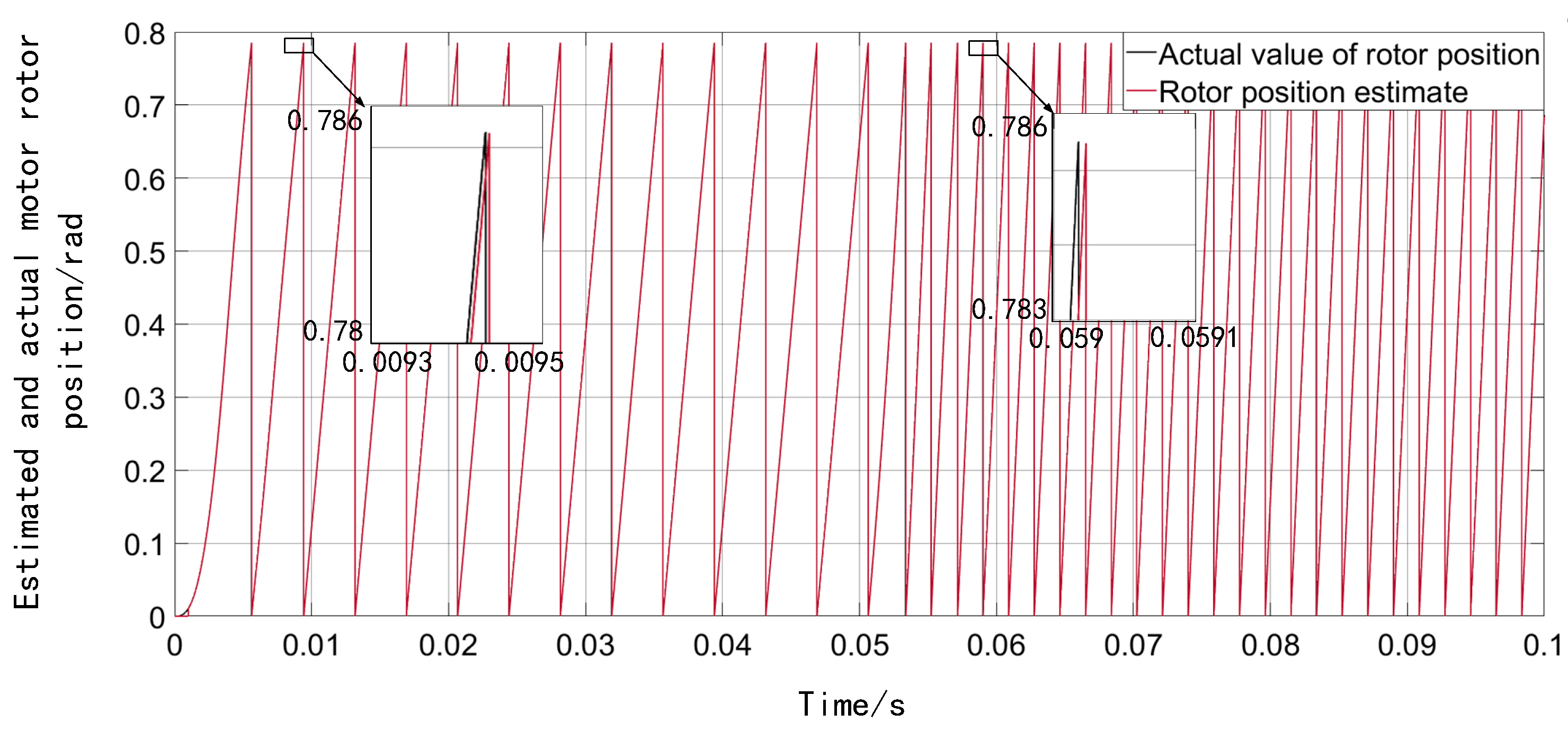
Figure 9 and
Figure 10 show the curve comparison diagrams of the actual and estimated values of the motor speed and rotor position of the new and improved SMO, respectively. First, the motor speed is set to 50 rad/s, and the speed suddenly changes to 100 rad/s at 0.05 s.
Comparing
Figure 9 with
Figure 2,
Figure 3 and
Figure 10 respectively, the new improved SMO greatly reduces high-frequency chattering and phase delay when the system is running at high speed compared to the traditional SMO, and the system has a faster convergence rate and faster, better tracking performance.
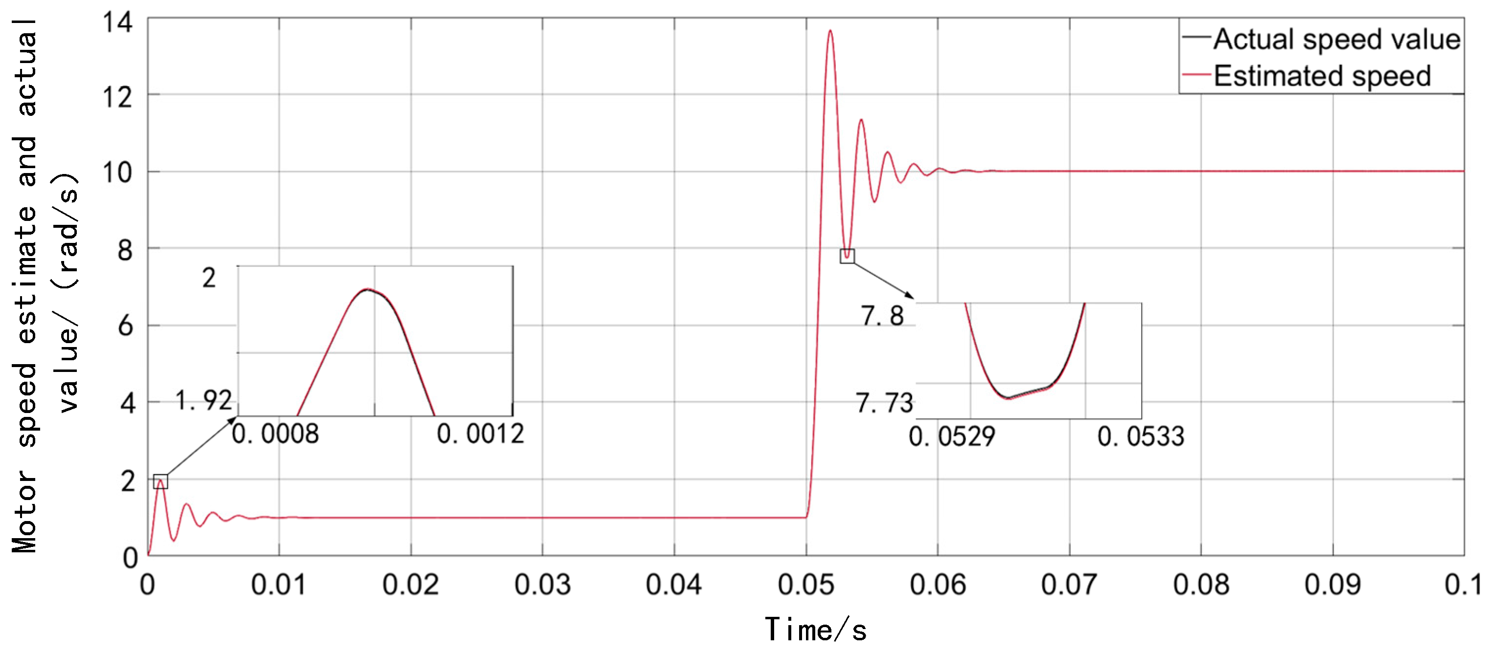
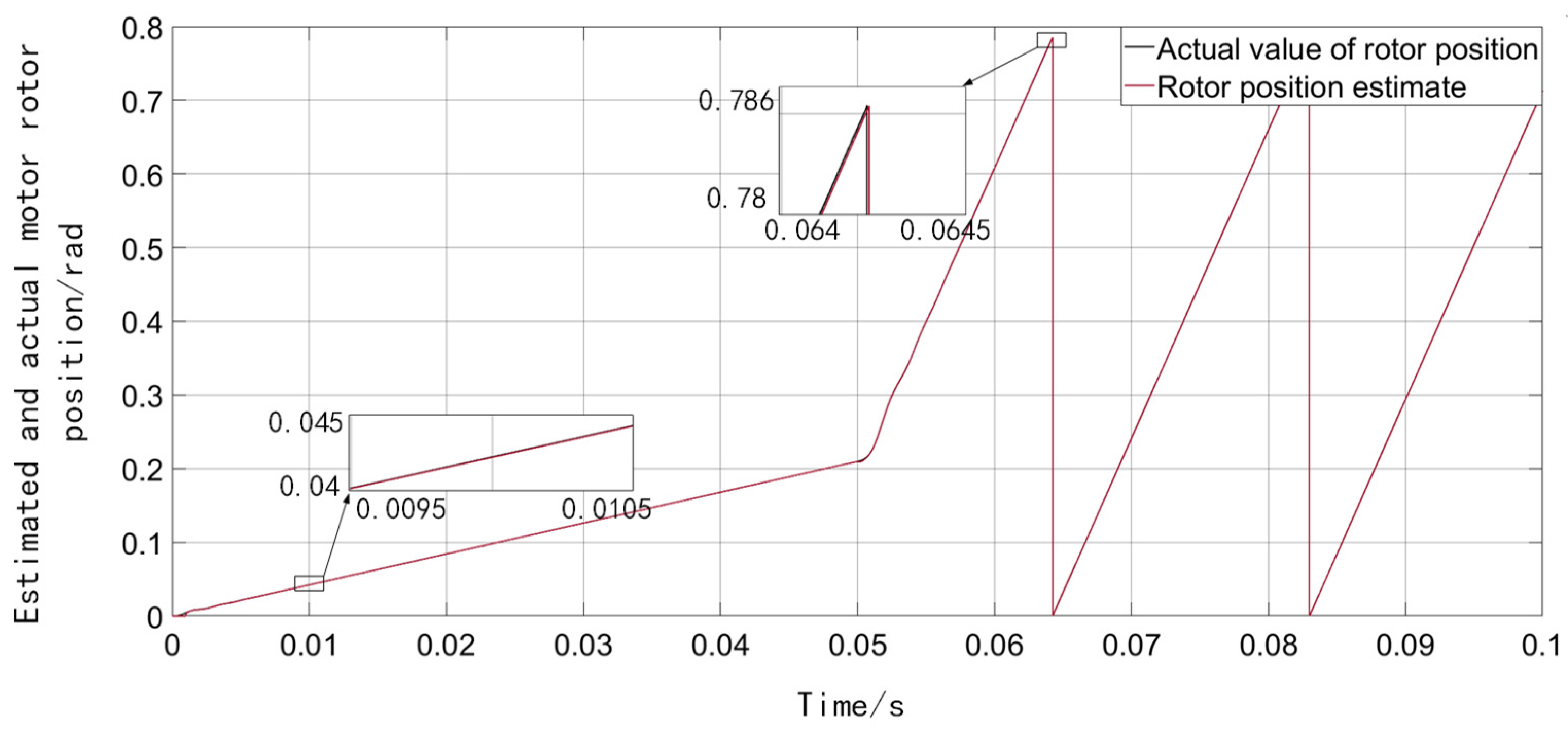
Figure 11 and
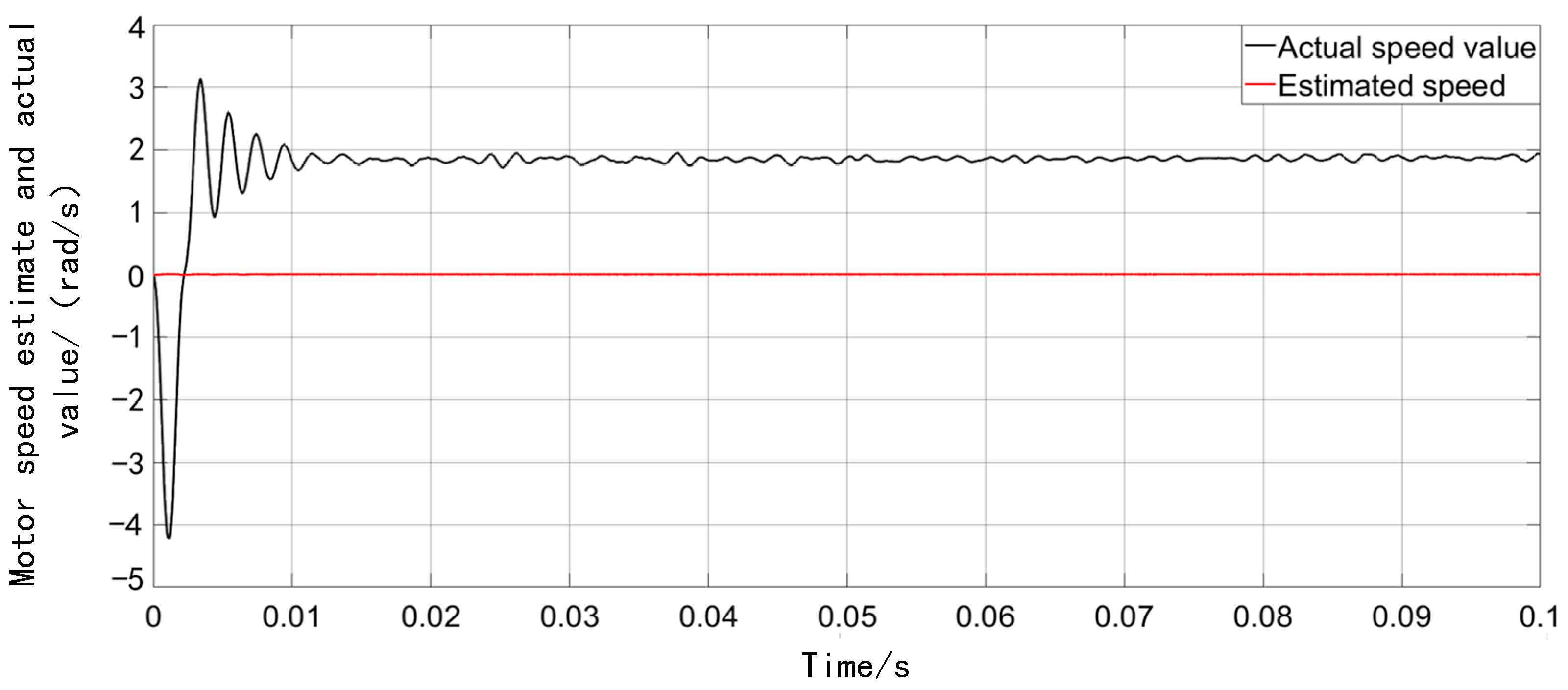
Figure 12 show the curve comparison diagrams of the motor speed and rotor position of the new and improved SMO running at low system speeds. First, the motor speed is set to 1 rad/s and then the speed changes to 10 rad/s at 0.05 s.
Comparing
Figure 4 and
Figure 11, the improved SMO based on the sigmoid function and RLS adaptive filter not only solves the problem of traditional SMO failure in the low-speed section, but also the high-frequency chattering that occurs during system operation.
In
Figure 11, the newly improved SMO can accurately estimate the position of the motor rotor when the system is running at low speed.
From
Figure 11 and
Figure 12, the newly improved SMO based on the sigmoid function and the RLS adaptive filter solves the problem of the fundamental wave model control strategy when taking the sliding mode control strategy. It is difficult to control the motor speed, rotor position, and other information at low speeds. There is a problem of making estimates.
To more intuitively demonstrate the improved performance of the improved SMO for motor speed and rotor position estimation accuracy compared with the traditional SMO, the simulation test was specially selected in the low-speed section where the back EMF is small.
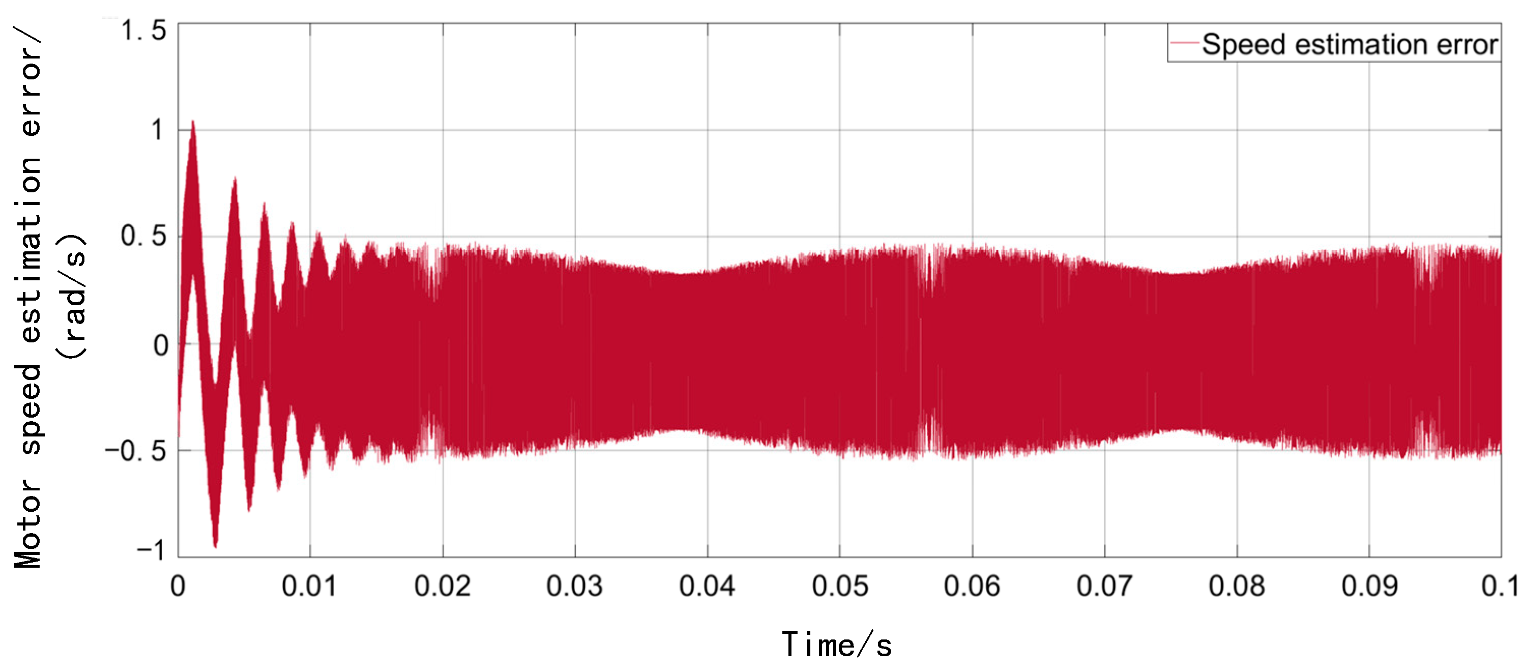
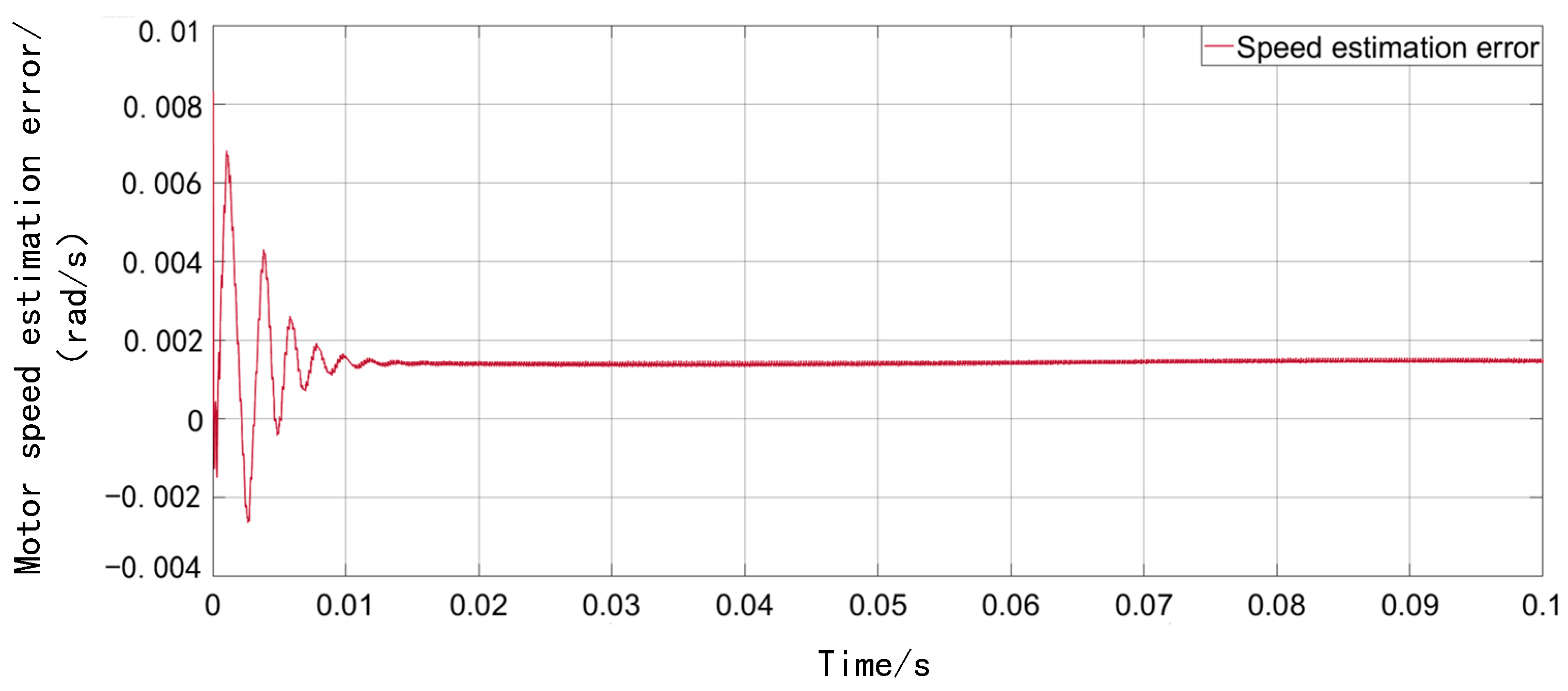
Figure 13 and
Figure 14 show the variation curves of the estimation error of the motor speed for the traditional SMO and the new improved SMO under the system of low-speed operating conditions. The motor speed is set to 10 rad/s.
Comparing
Figure 13 with
Figure 14, the speed estimation error of the traditional SMO is about ±0.5 rad/s, and the speed estimation error of the new improved SMO is about 0.0015 rad/s. This proves that the new improved SMO is optimized for the accuracy of motor speed estimation.
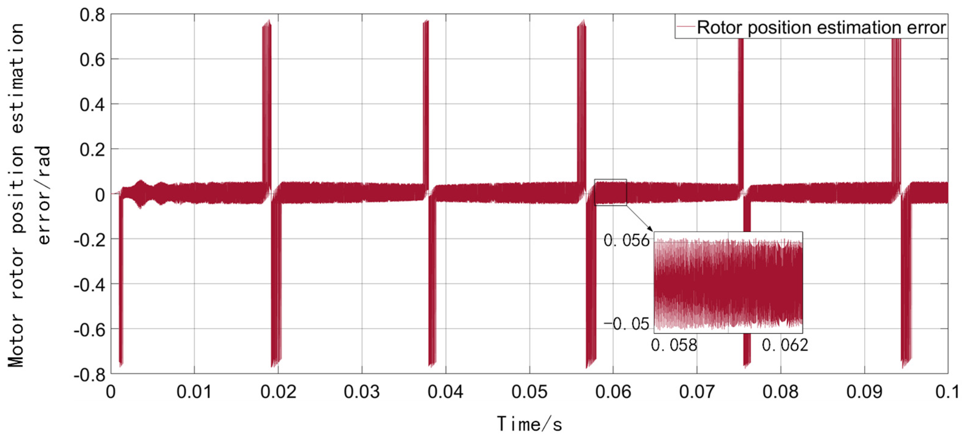
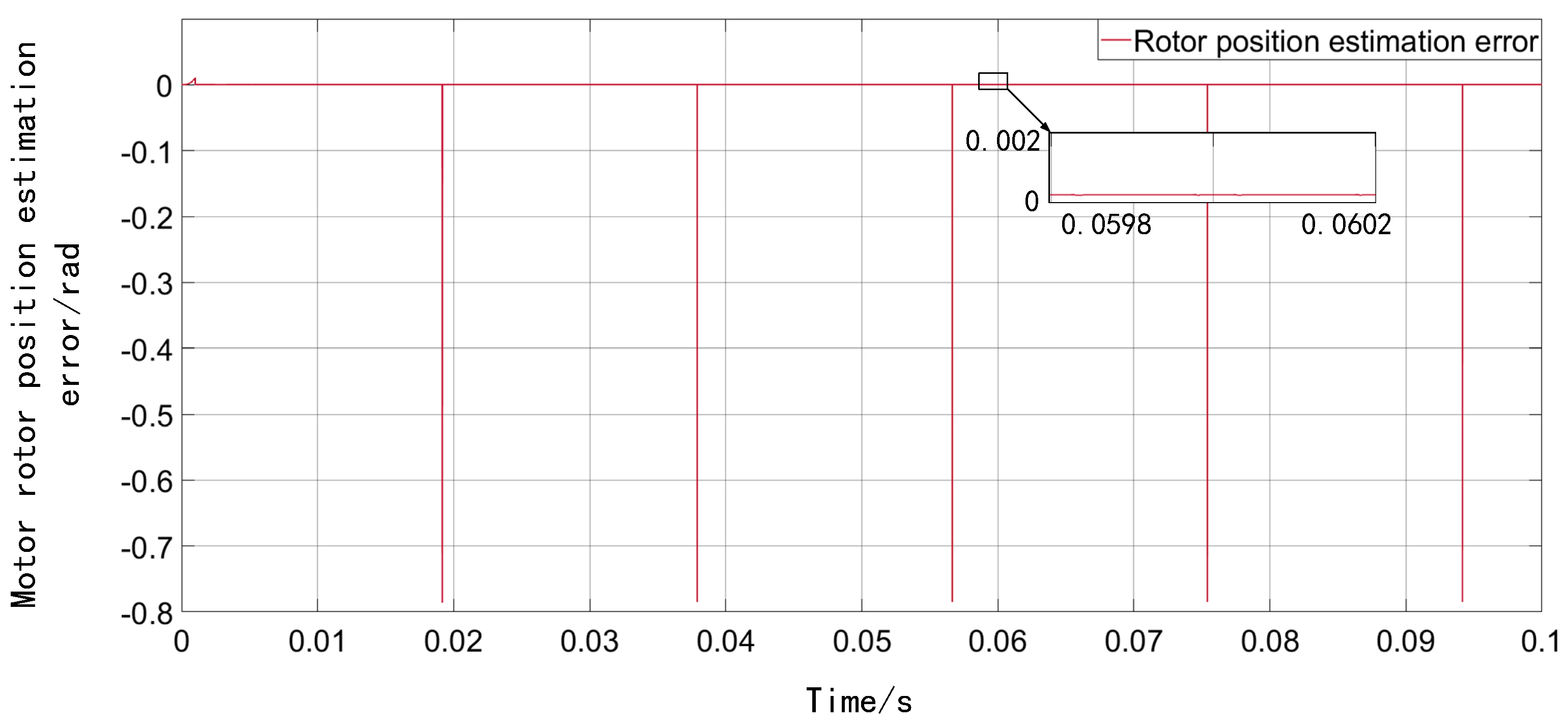
Figure 15 and
Figure 16 show the variation curves of the estimation error of the rotor position of the motor under the low-speed operating conditions of the traditional SMO and the new improved SMO, respectively. The motor speed is set to 10 rad/s.
Comparing
Figure 15 with
Figure 16, it can be seen intuitively that the rotor position estimation error of the traditional SMO is about ±0.05 rad, and the rotor position estimation error of the new improved SMO is about 0.0005 rad. This proves that the new improved SMO is optimized for the estimation accuracy of the motor rotor position.
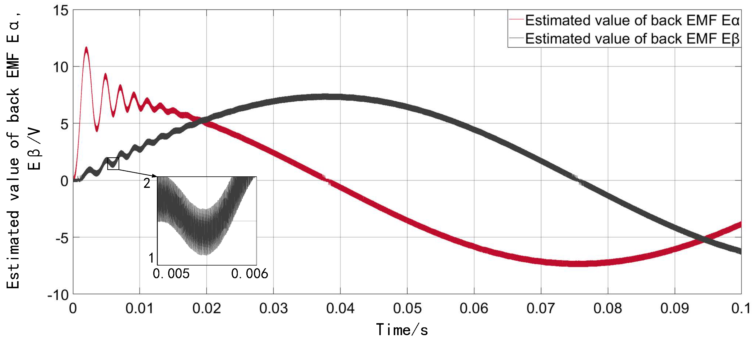
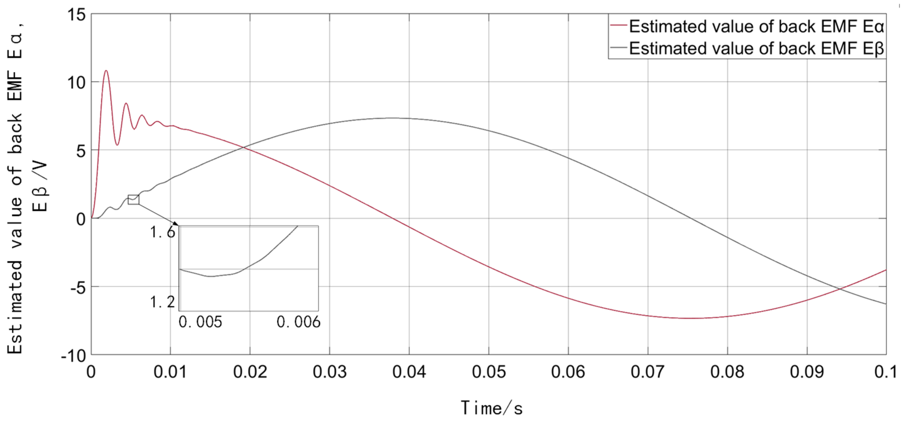
Figure 17 and
Figure 18 show the variation curves of the estimated values of the opposite electromotive force of the motor under the low-speed operating conditions of the traditional SMO and the new improved SMO (the red curve is
and the black curve is
). The motor speed is set to 10 rad/s.
Comparing
Figure 17 and
Figure 18, intuitively, the RLS adaptive filter used in the new improved SMO has greatly improved the filtering performance compared to the low-pass filter used in the traditional SMO. The precise back-EMF signal lays the foundation for the new and improved SMO to achieve a better observation effect on the motor speed and rotor position information in the full speed section.
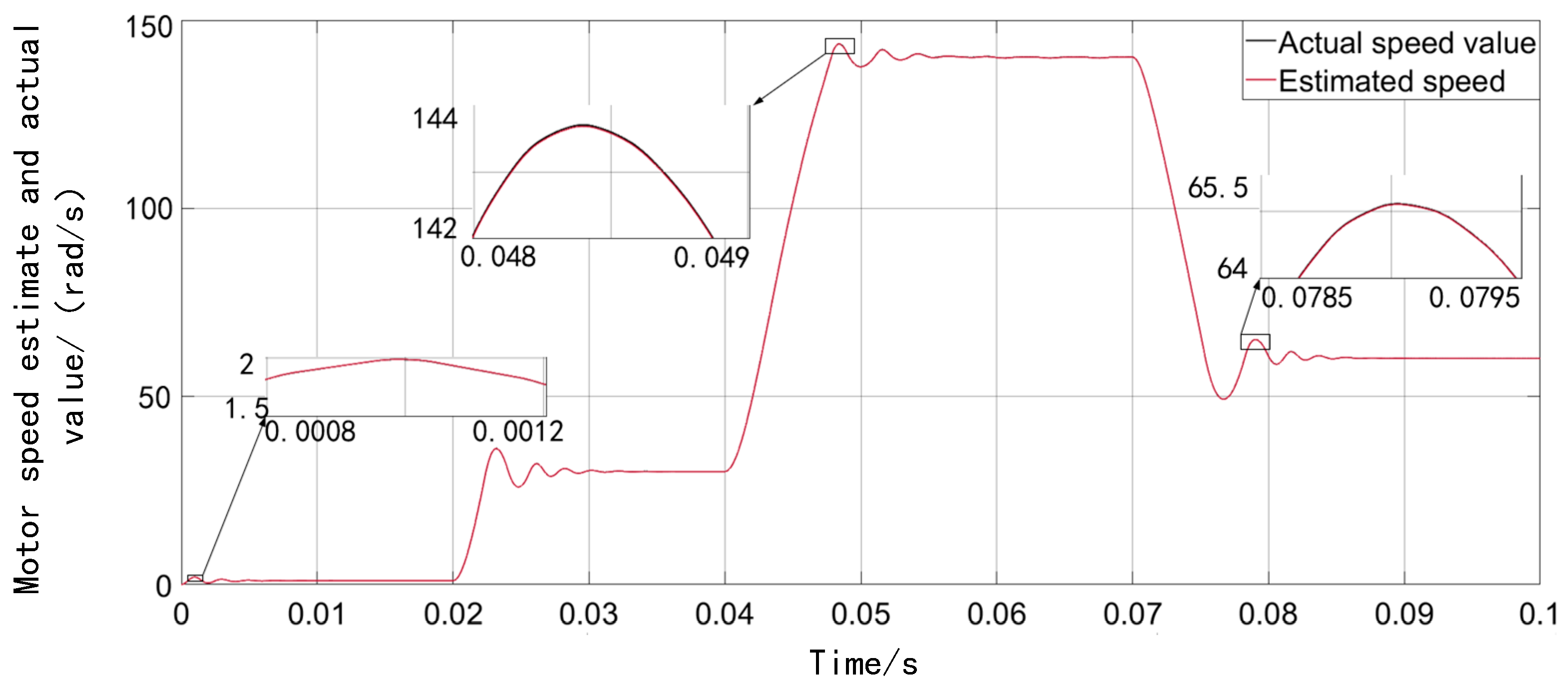
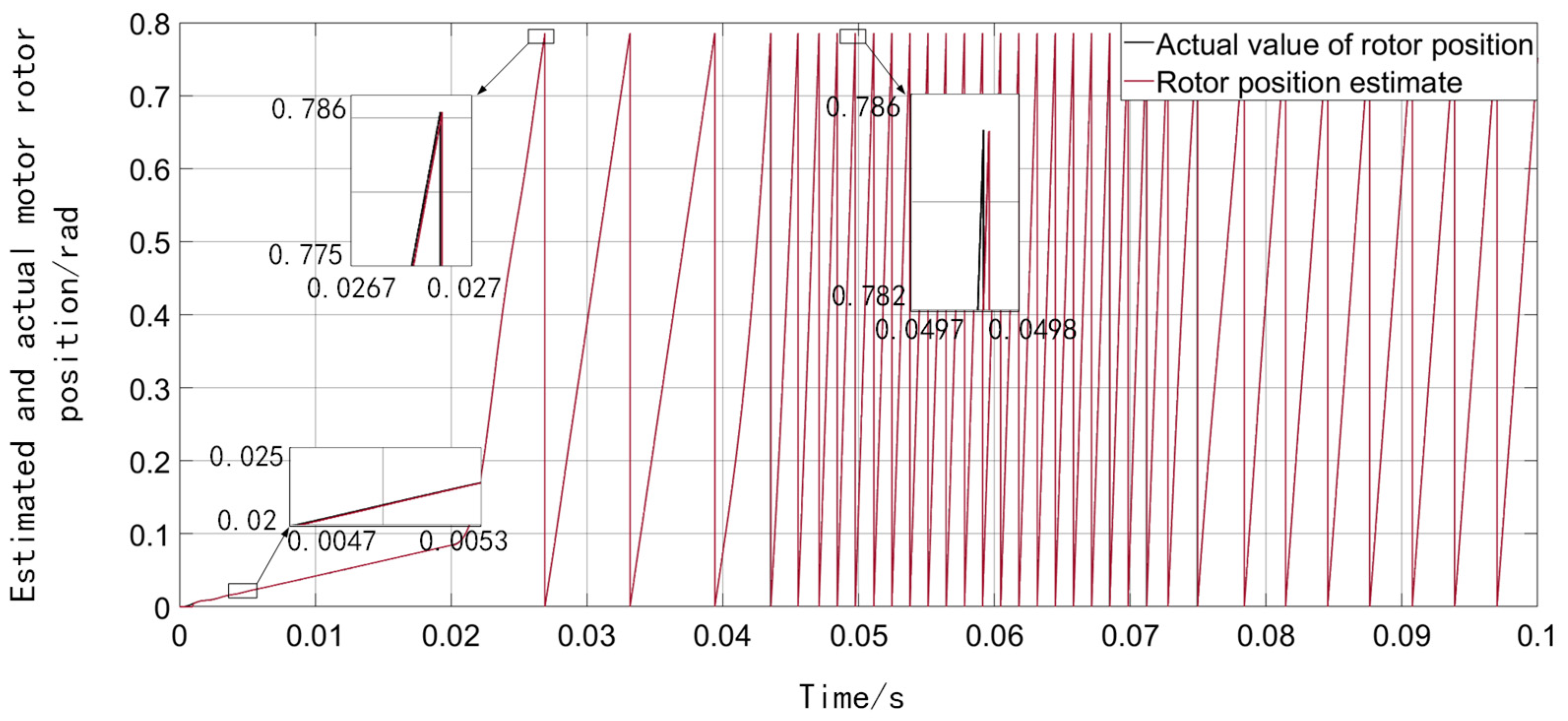
To observe the phenomenon that the motor continuously changes the speed during the driving process of an electric vehicle,
Figure 19 and
Figure 20 compare the actual and estimated values of the motor speed and rotor position of the new and improved SMO when the system is running at full speed (the red curve is the estimated value, and the black curve is the actual value). First, the given motor speed is 1 rad/s, then the speed changes to 30 rad/s at 0.02 s, the speed changes to 140 rad/s at 0.04 s, and the speed changes to 60 rad/s at 0.07 s.
From
Figure 19 and
Figure 20, the new and improved SMO based on the sigmoid function and the RLS adaptive filter can accurately estimate the motor speed and rotor position information at the full speed.
6. Experimental Verification
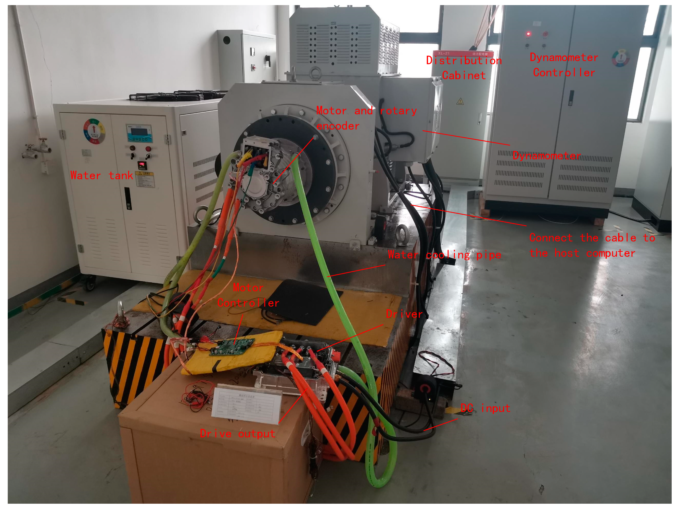
To verify the feasibility and practicability of the new improved SMO observer proposed in this paper, the new improved SMO observer was tested and verified with the aid of the experimental platform shown in
Figure 21. The experiment part used the 150 kW simulation integrated equipment of Chongqing Dema Company, and the motor controller adopted the Renesas RH850 automotive-grade motor control chip that meets ISO26262 functional safety. The specific parameters of PMSM are as follows: rated voltage 350 V, rated current 120 A, rated power 25 kW, rated torque 80 Nm, rated speed 3000 rpm, peak torque 175 Nm, peak speed 9000 rpm, peak power 55 kW.
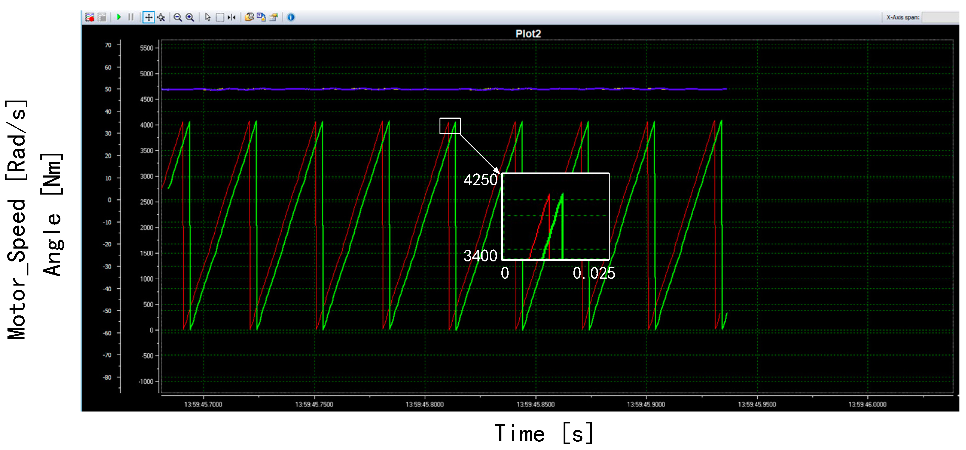
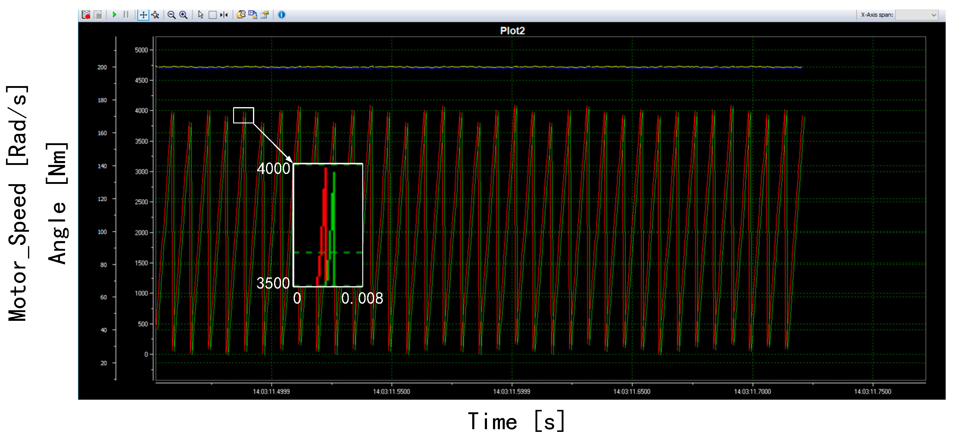
First, load the new improved SMO observer and the traditional SMO observer proposed in this paper into the motor controller respectively. After starting the device, the signal is transmitted through the Controller Area Network (CAN). The upper computer can receive the motor speed and rotor position information measured by the rotary encoder, as well as the motor speed estimated by the new and improved SMO observer. Rotor position information. The measured data detected by the rotary encoder are regarded as the real data. The feasibility of control strategy based on the new and improved SMO observer was verified by comparing the graphs of the estimated and measured data. In the experimental results, the unified yellow curve is the measured value of the motor speed, the blue curve is the estimated value of the motor speed, the red curve is the measured value of the motor rotor position, and the green curve is the estimated value of the motor rotor position.
Figure 22 is a graph comparing the actual and estimated values of the motor speed and rotor position based on the traditional SMO observer. The speed of the given motor is 50 rad/s.
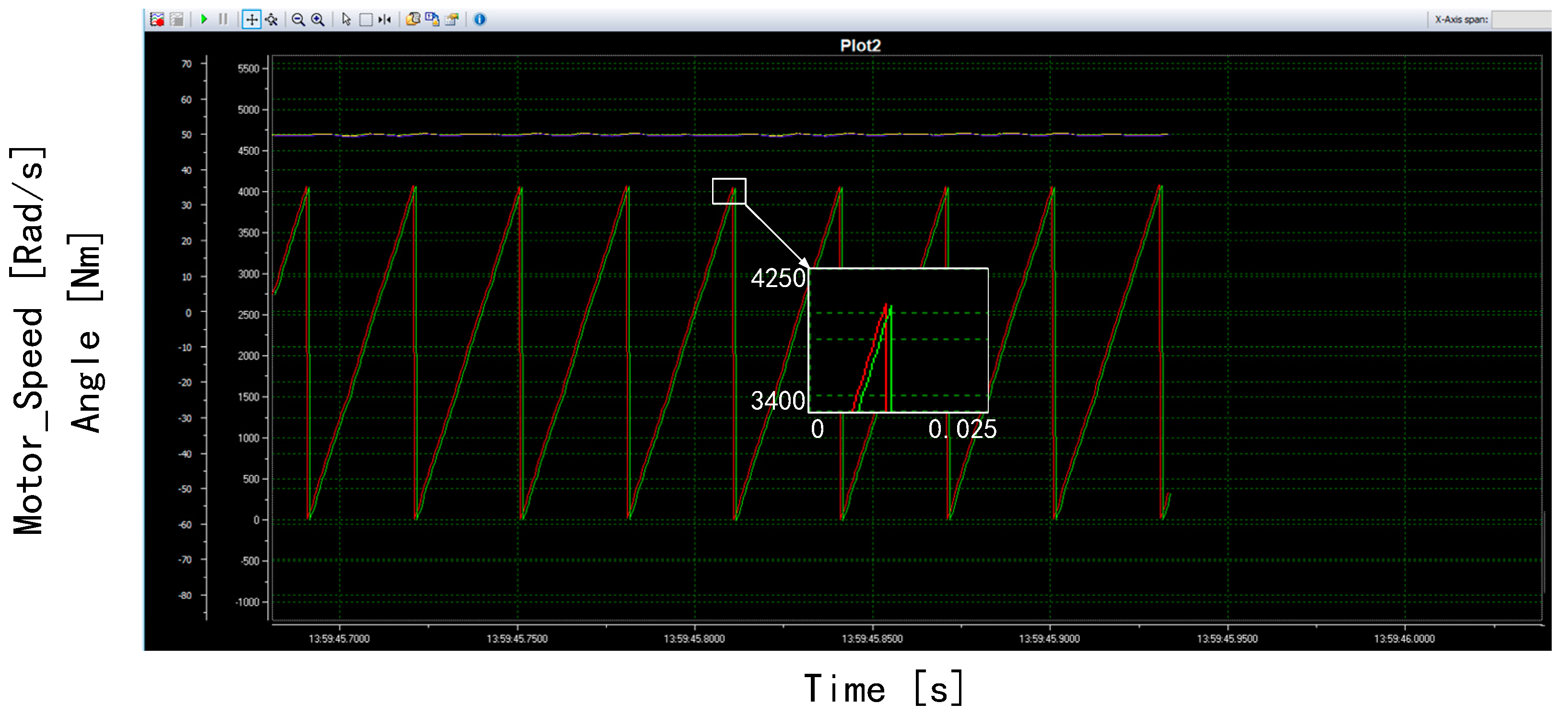
Figure 23 is a graph comparing the actual and estimated values of motor speed and rotor position based on the new and improved SMO observer. The speed of the given motor is 50 rad/s.
Comparing the yellow and blue curves in
Figure 23, the new and improved SMO observer has a higher estimation accuracy for the motor speed. Comparing the green and red curves, the new and improved SMO observer also has better estimation accuracy for the estimation of the motor rotor position.
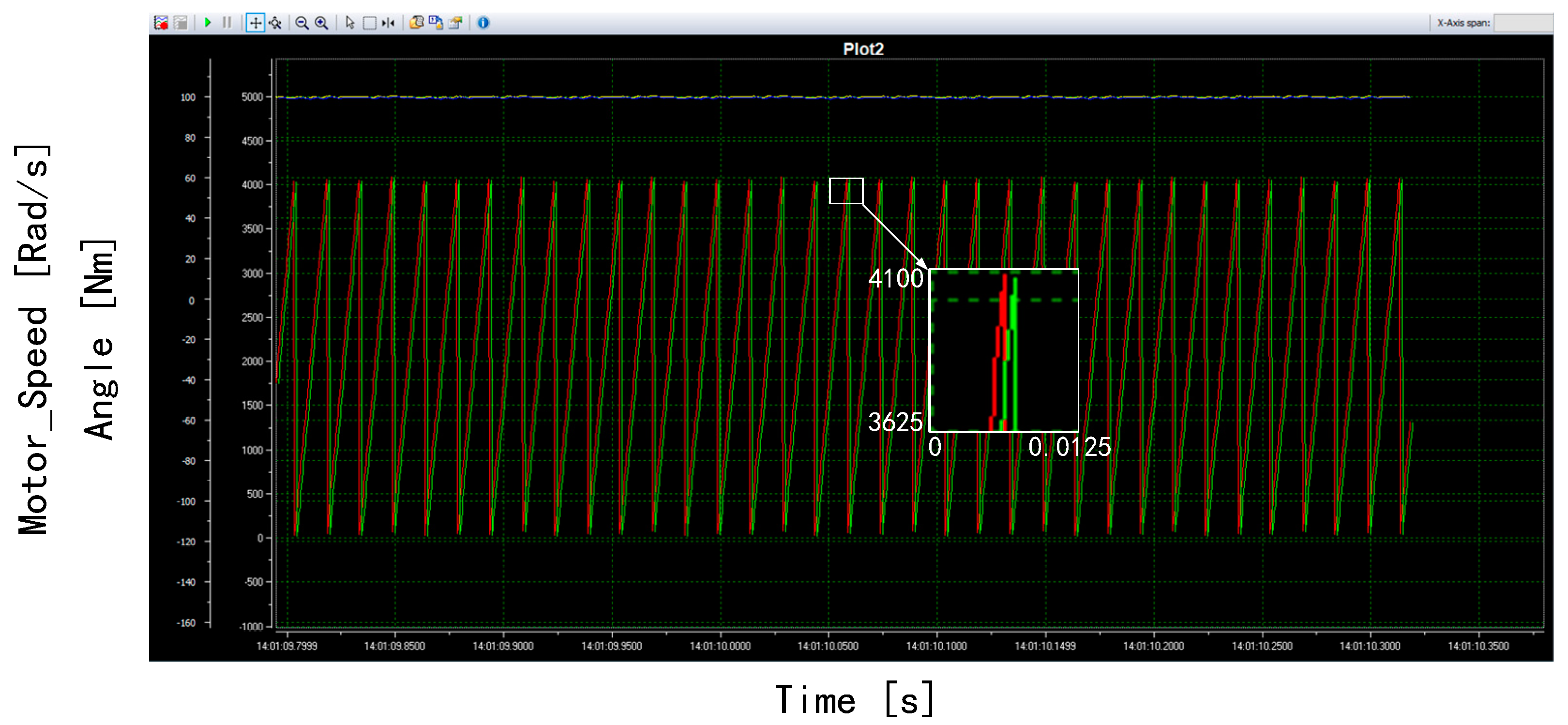
Figure 24 is a graph comparing the actual and estimated values of motor speed and rotor position based on the new and improved SMO observer. The speed of the given motor is 100 rad/s.
Comparing the yellow and blue curves in
Figure 24, the new and improved SMO observer has a higher estimation accuracy for the motor speed. Comparing the green and red curves, the new and improved SMO observer also has better estimation accuracy for the estimation of the motor rotor position.
Figure 25 is a graph comparing the actual and estimated values of motor speed and rotor position based on the new and improved SMO observer. The speed of the given motor is 200 rad/s.
Comparing the yellow and blue curves in
Figure 25, it can be concluded that the new and improved SMO observer has a higher estimation accuracy for the motor speed. Comparing the green and red curves, the new and improved SMO observer also has better estimation accuracy for the estimation of the motor rotor position. Comparing
Figure 22,
Figure 23,
Figure 24 and
Figure 25, when the motor is at 200 rad/s, the rotor position angle of the motor is missing. This is because the CAN transmission cycle is slow when the motor speed is high, and the transmitted angle is intermittent.
7. Conclusions
This paper proposes an improvement strategy for the problems of high-frequency chattering, phase delay, low system convergence rate, and the inability to estimate the motor speed and rotor position in the low-speed section that exists in the traditional SMO control strategy of SPMSM. Simulation analysis and experiments verified the feasibility of the improved scheme. The sigmoid function was used to replace the signum function in the traditional synovial observer to achieve a system with smoother operation and faster convergence rate. Moreover, the high frequency chattering phenomenon of the system was greatly improved, and adaptive filtering with a variable cutoff frequency introduced. The filter replaces the low-pass filter to eliminate the harmonics and chattering and adaptively compensates the extracted electromotive force signal to improve the detection accuracy of the back electromotive force signal. In this way, the estimation error caused by the phase delay is reduced, the convergence rate of the synovial observer is further improved, and the synovial control strategy can also have a better observation effect in the low speed section. This method breaks the limitation that the sensor-less control strategy of the permanent magnet synchronous motor mostly uses the high frequency injection method at low speed. It also realizes a single sensor-less control strategy at full speed. However, compared with the traditional SMO, the new improved SMO increases the complexity of the operation, so the execution time will increase relatively. This problem needs to be considered in practical engineering applications. How to increase the operation rate of this method is very worthwhile, it is worth studying and improving further.


