Theoretical Design and Experimental Validation of a Nonlinear Controller for Energy Storage System Used in HEV

 ,
,  ,
, 

Abstract
1. Introduction
2. Storage System Presentation and Modeling
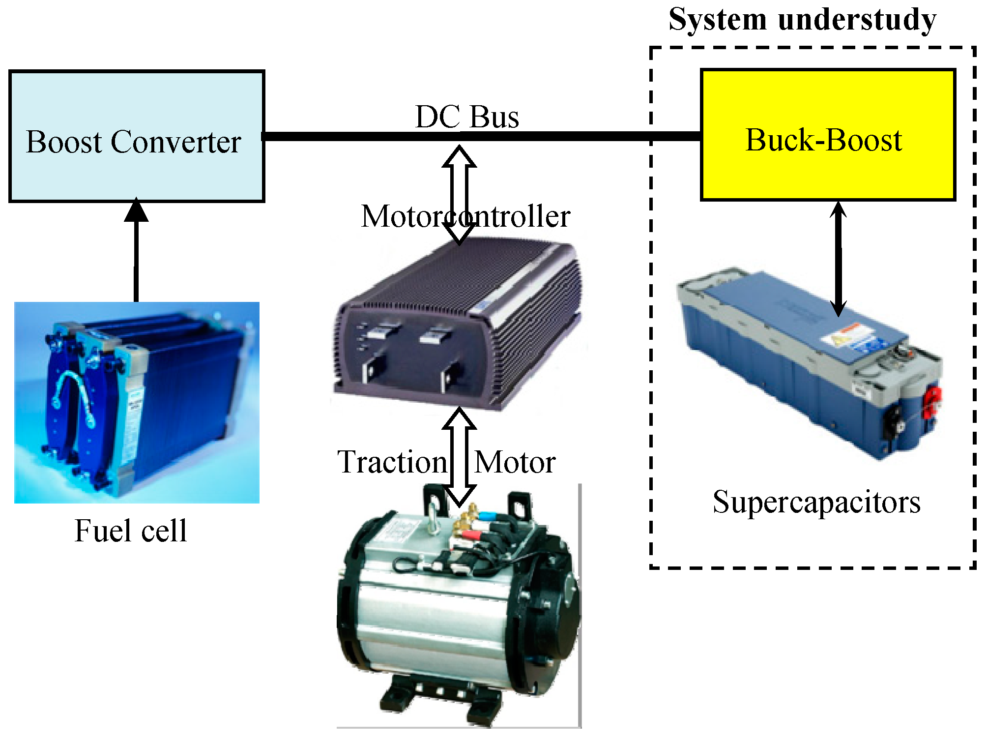
2.1. Storage System Presentation
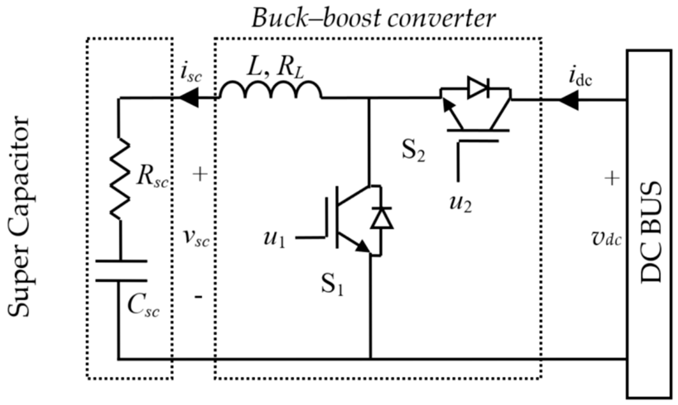
2.2. Modeling of a Reversible Power Buck–Boost Converter
- Boost mode operation (k = 1)
- Buck mode operation (k = 0)
3. Storage Sliding Mode Control and Stability Analysis
3.1. Control Objective
- (i).
- Monitoring of the supercapacitor current up to its reference,
- (ii).
- Asymptotic stability of the system.
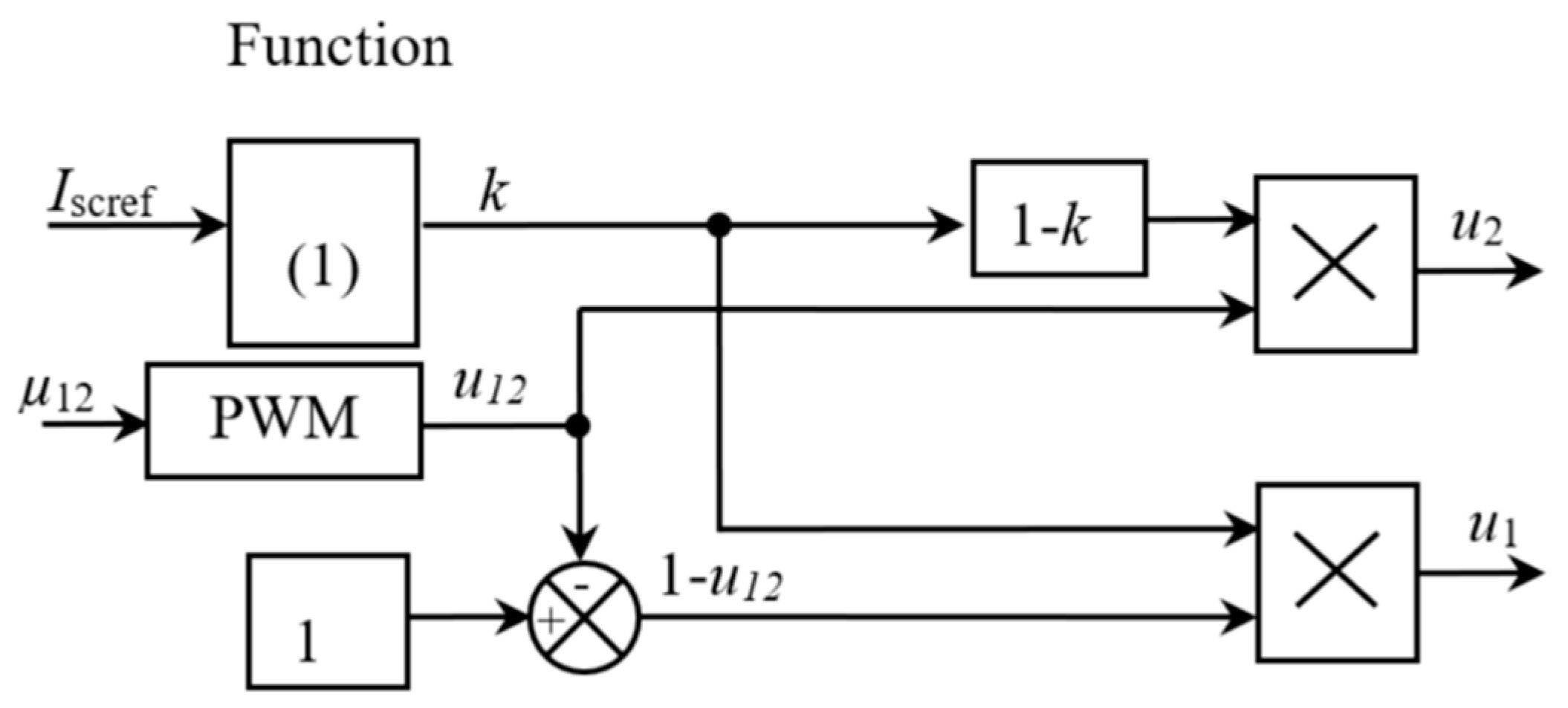
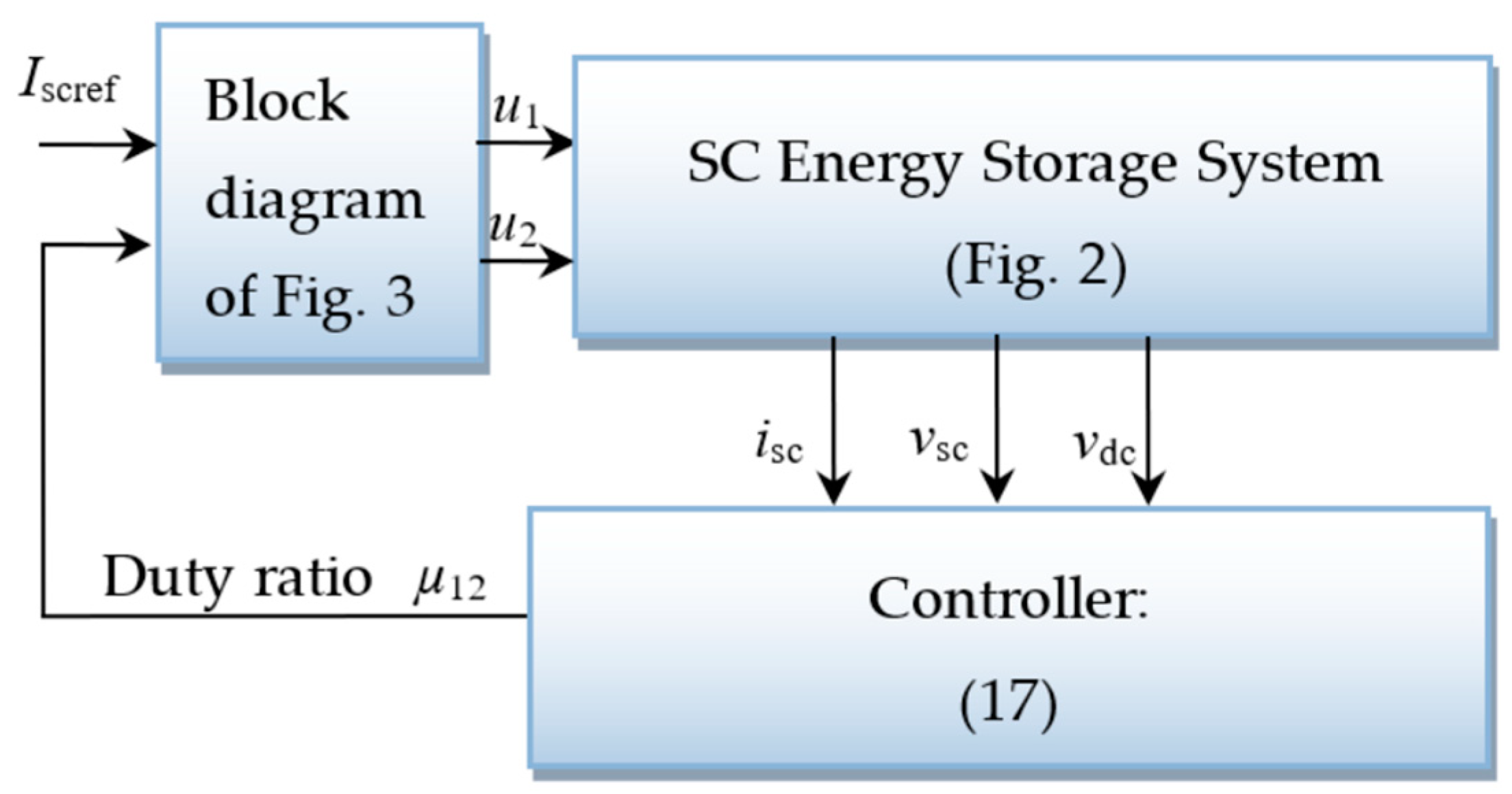
3.2. Sliding Mode Control
3.3. The Limitations of SMC Technique
4. Simulation and Experimental Results
4.1. System Characteristics
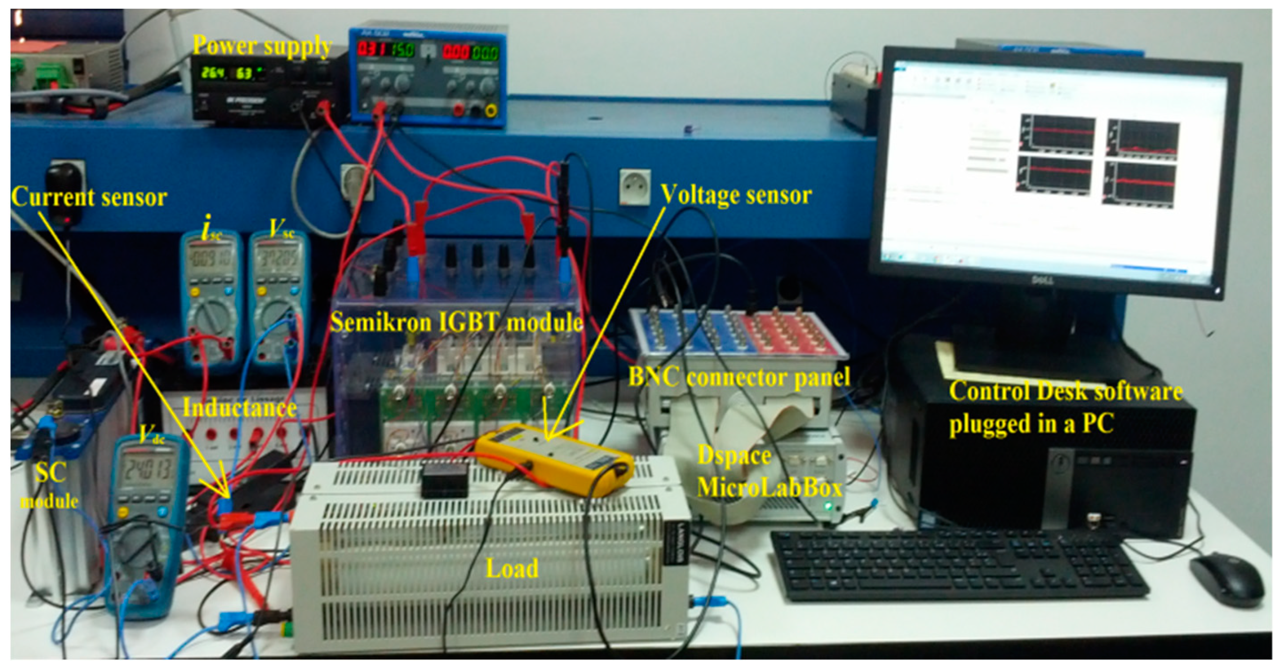
4.2. Simulation and Experimental Bench for SCSS Control
- -
- a power supply from BK Precision,
- -
- a dSPACE DS1202 with Control Desk®/software® plugged in a Pentium 4 personal computer,
- -
- a Semikron IGBT module (SEMITEACH),
- -
- a 16 V supercapacitor module of Maxwell,
- -
- one ferrite inductance,
- -
- one Hall effect current sensor,
- -
- one voltage sensor,
- -
- a load.
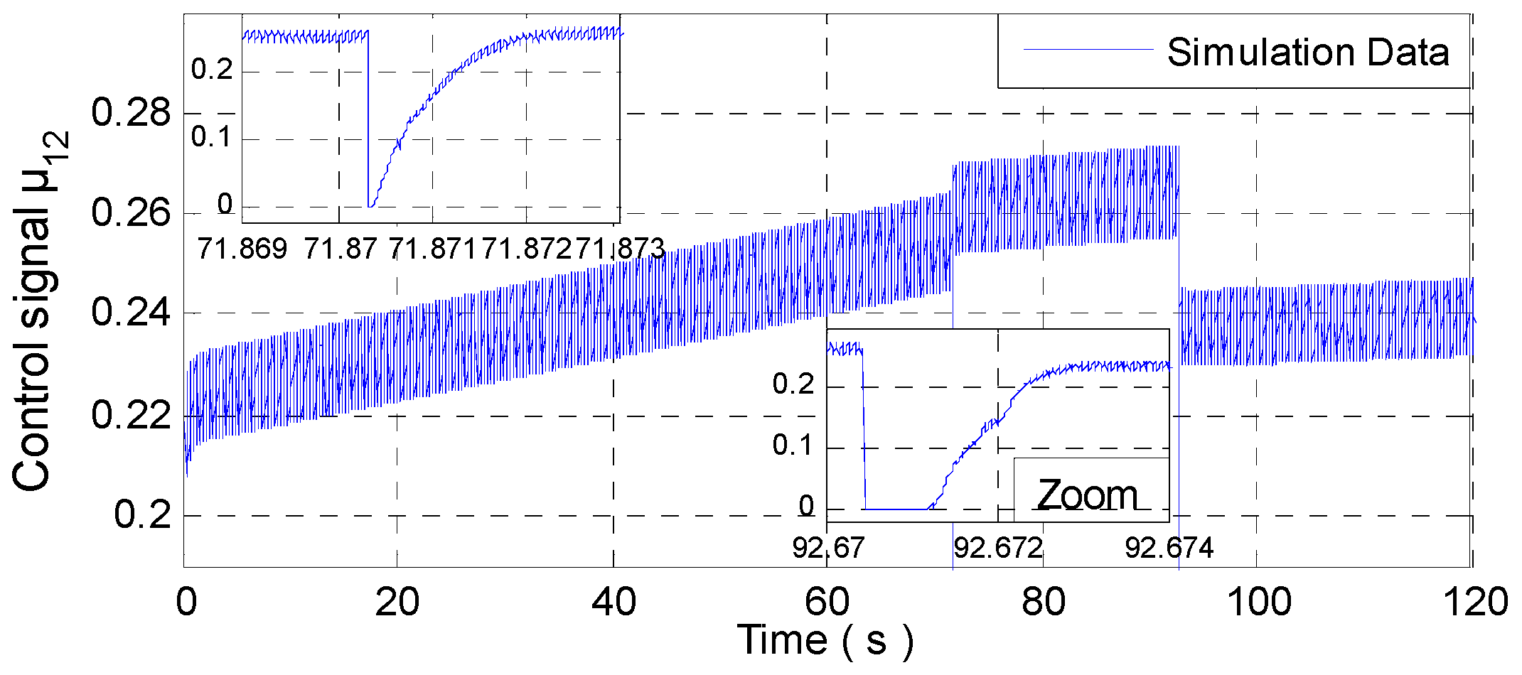
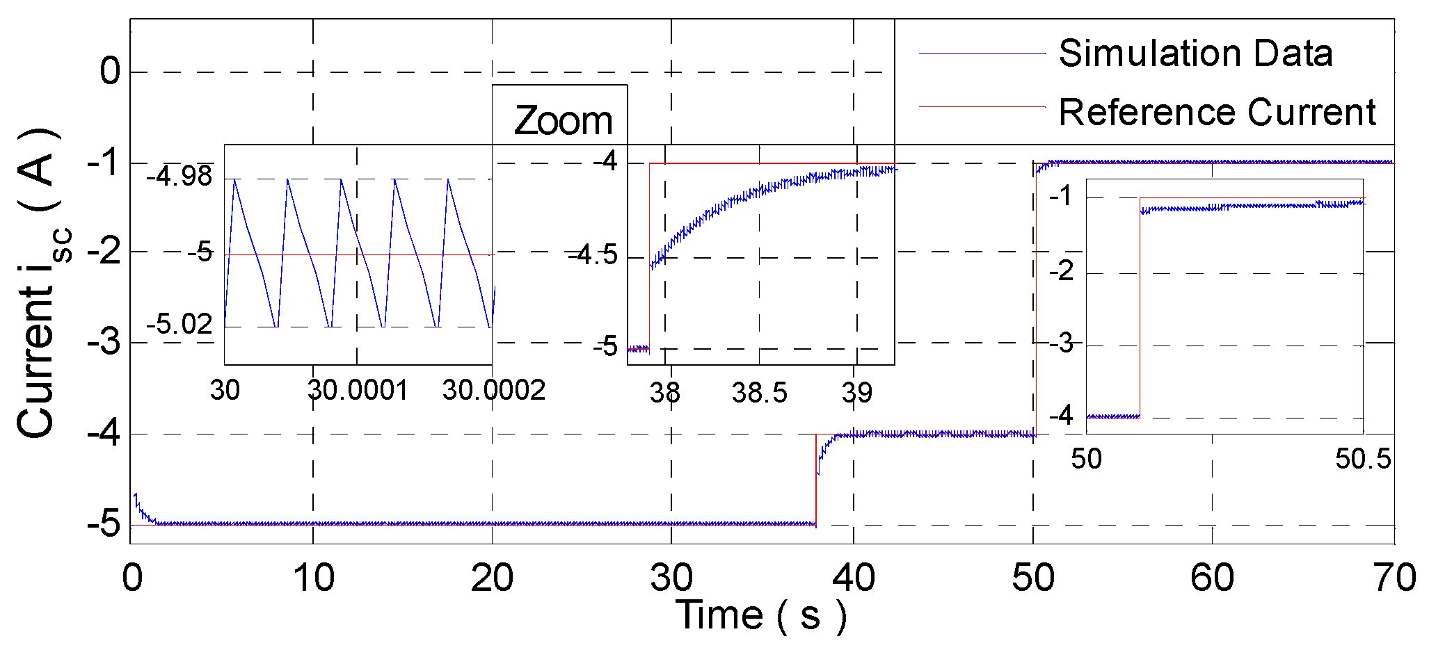
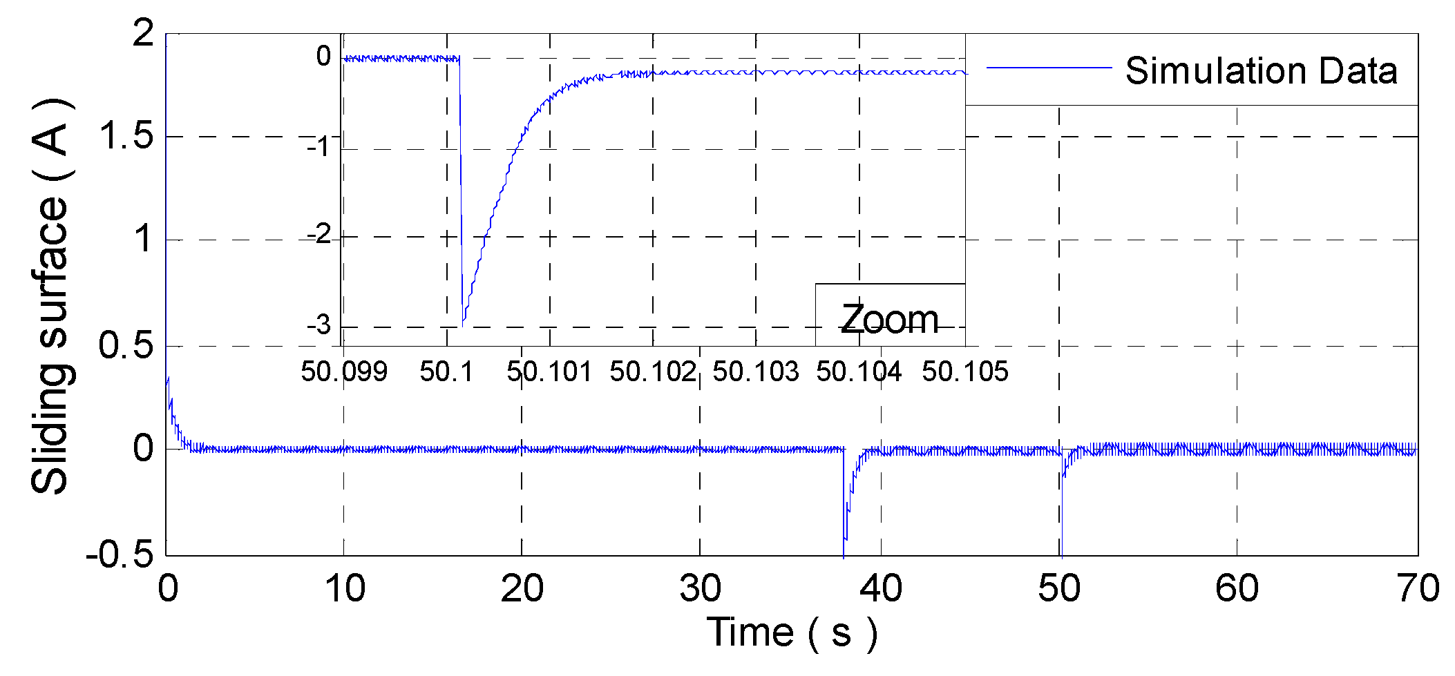
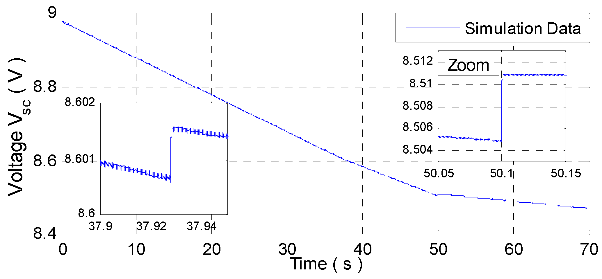
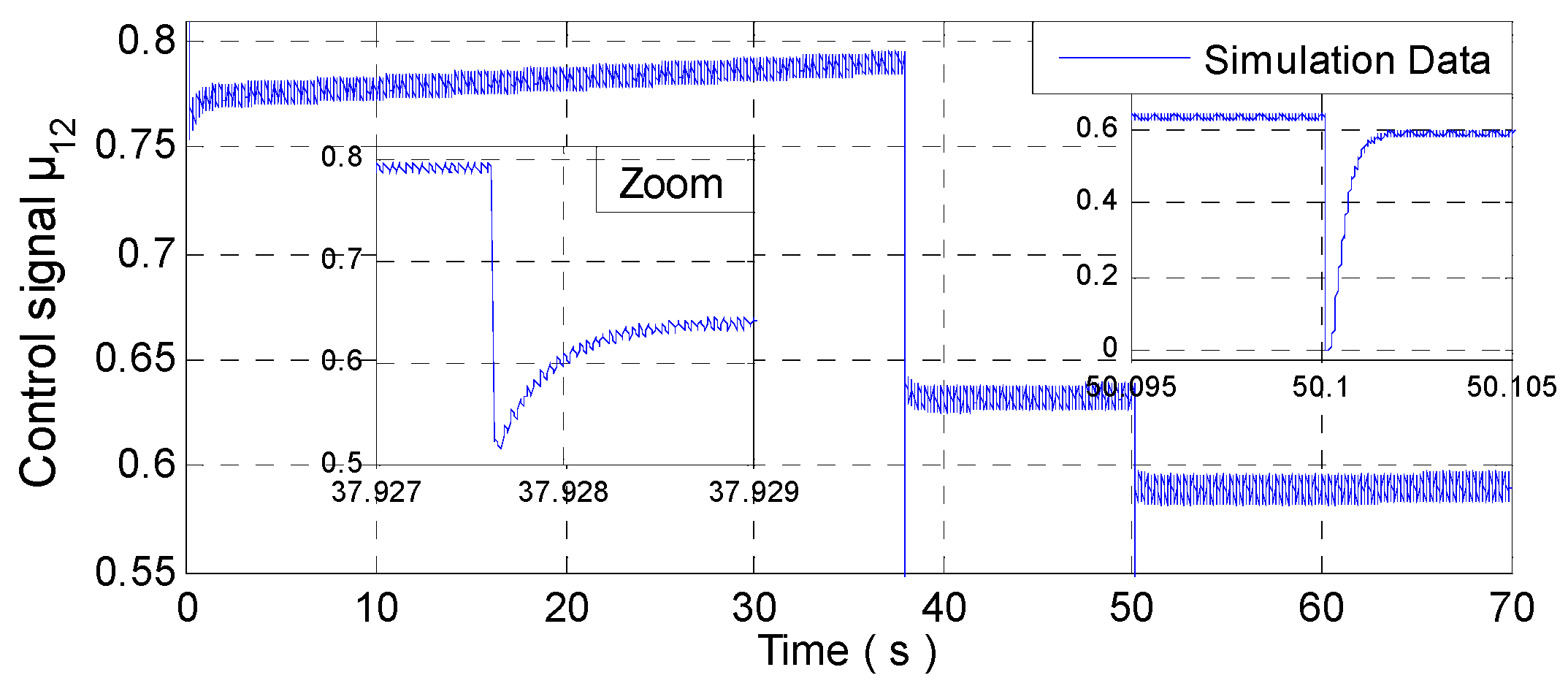
4.3. Figures and Simulation Results
- ▪
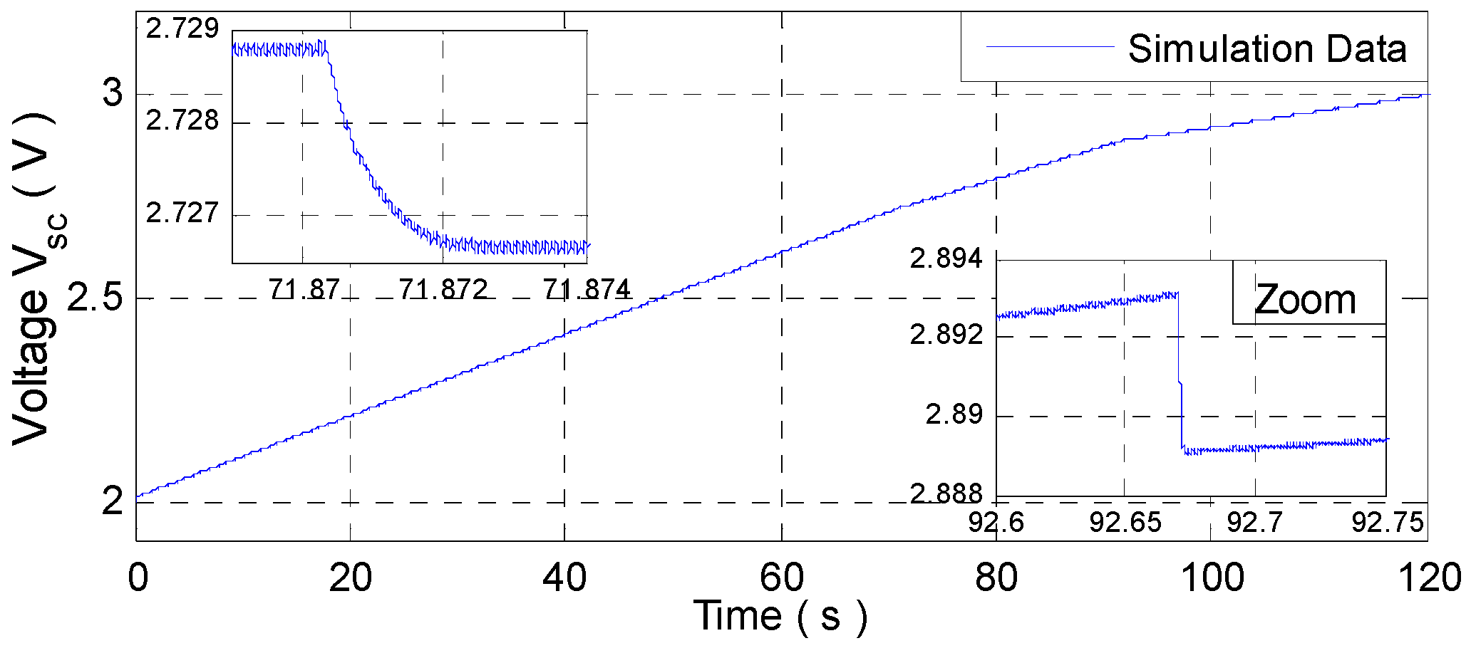
- Charging mode of SC (Buck operation, k = 0):
- ▪
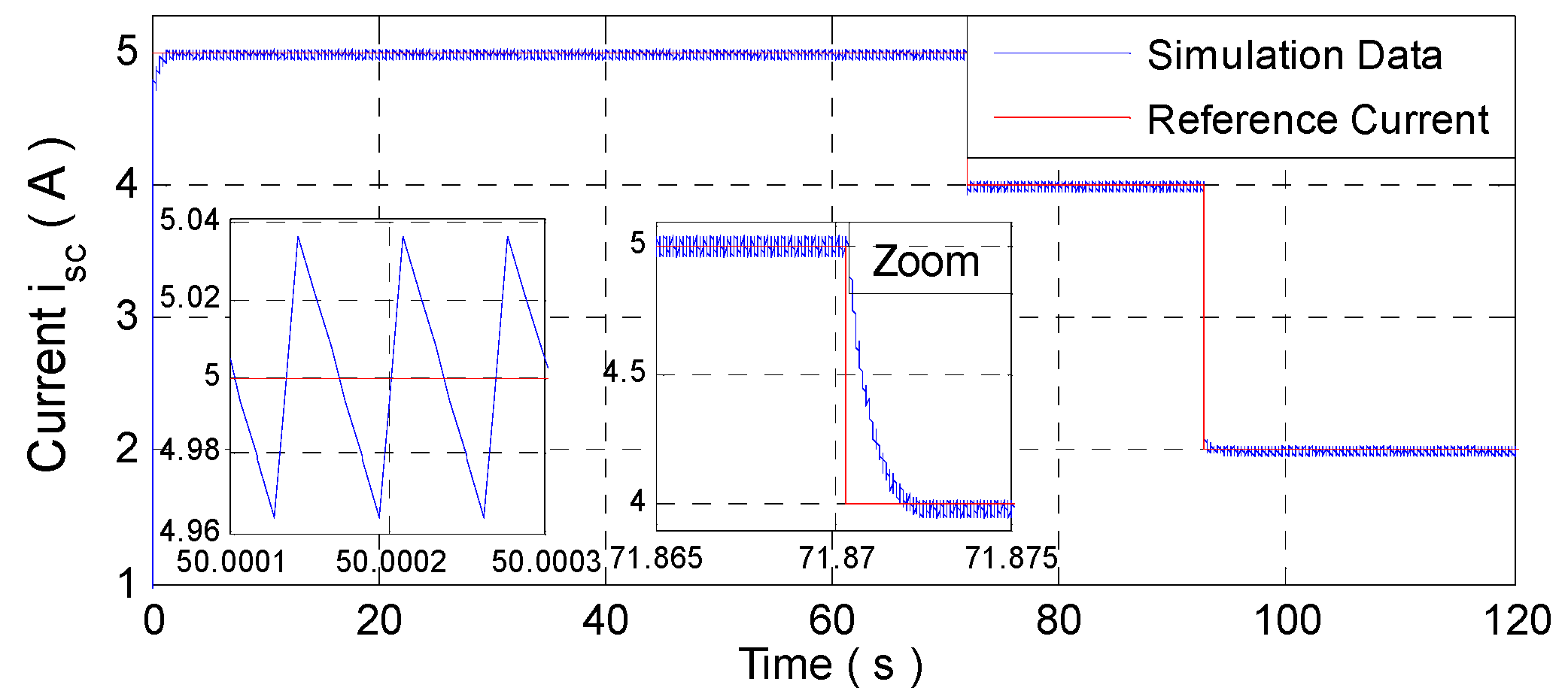
- Discharging mode of SC (Boost operation, k = 1)
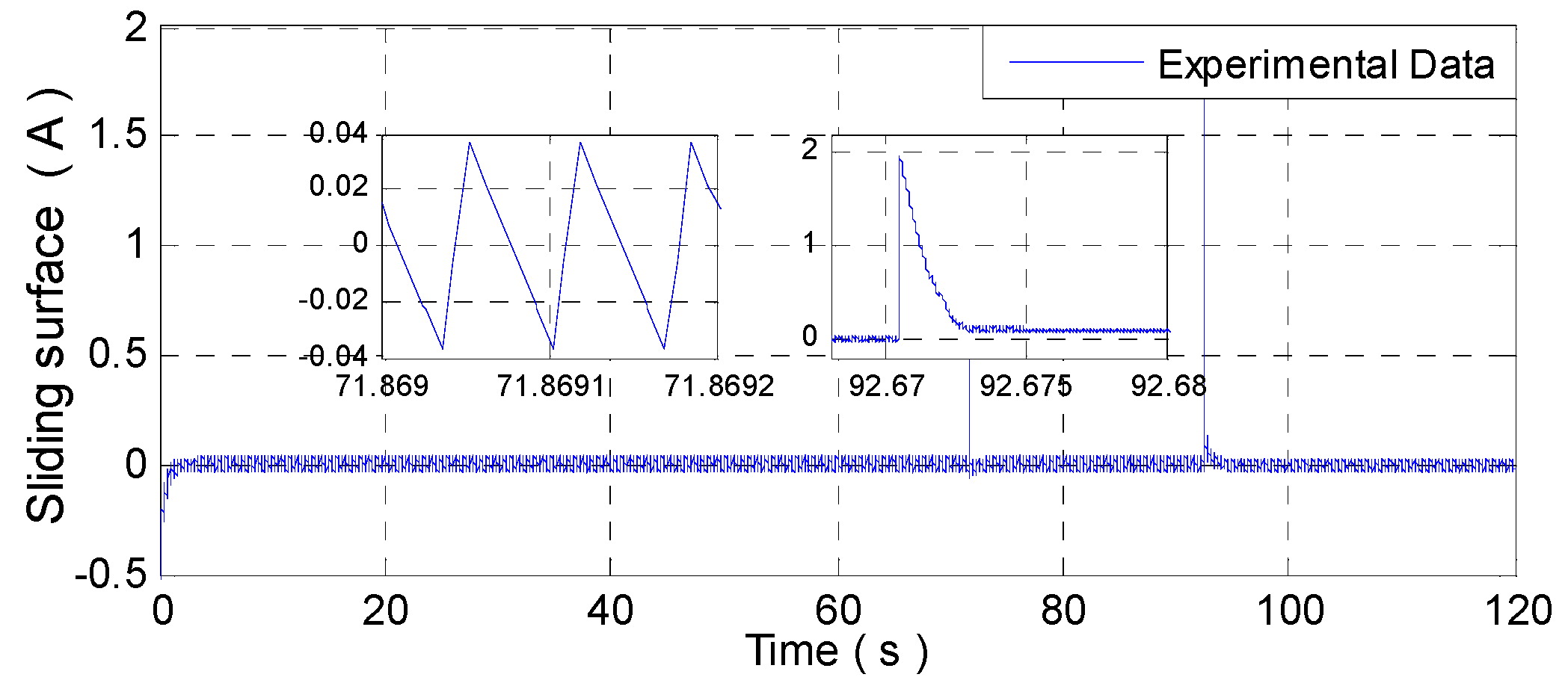
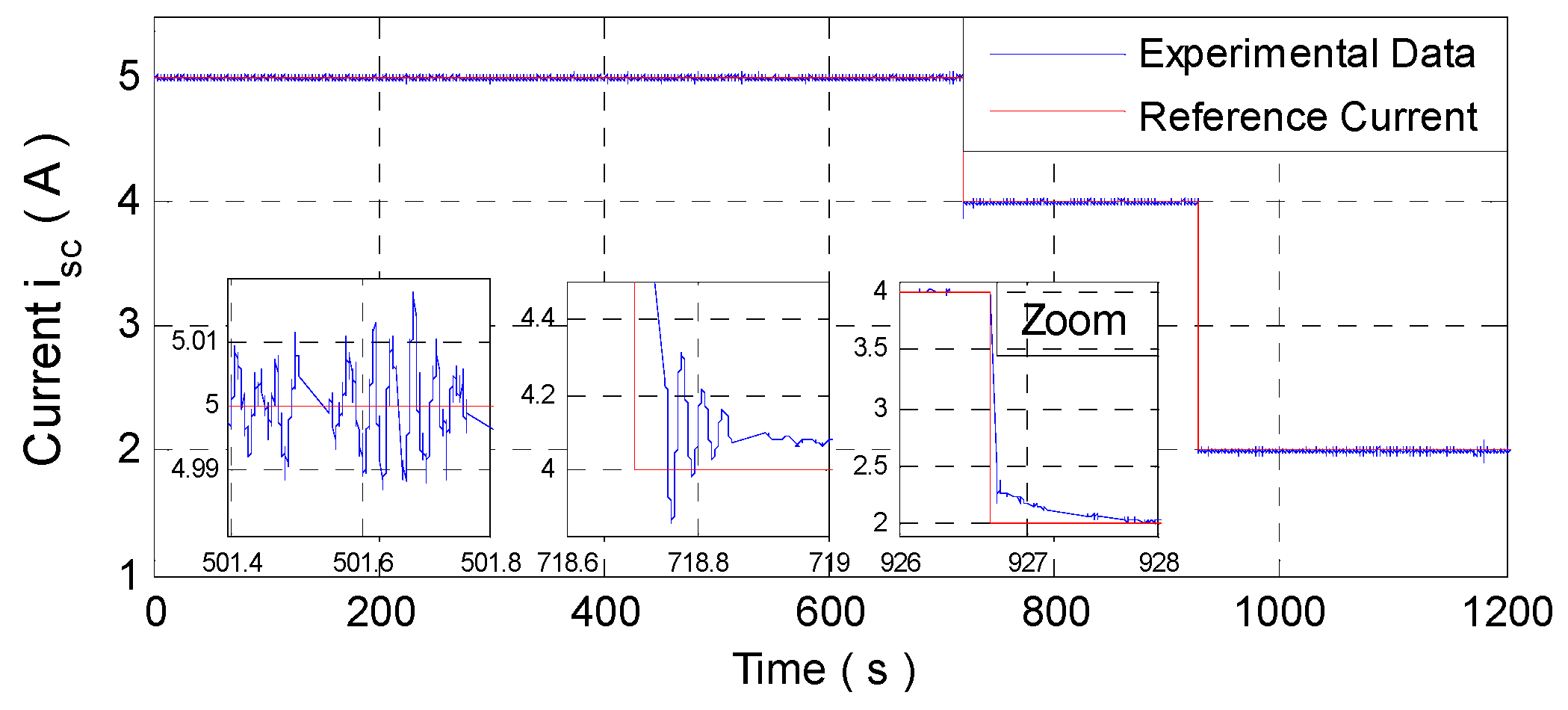
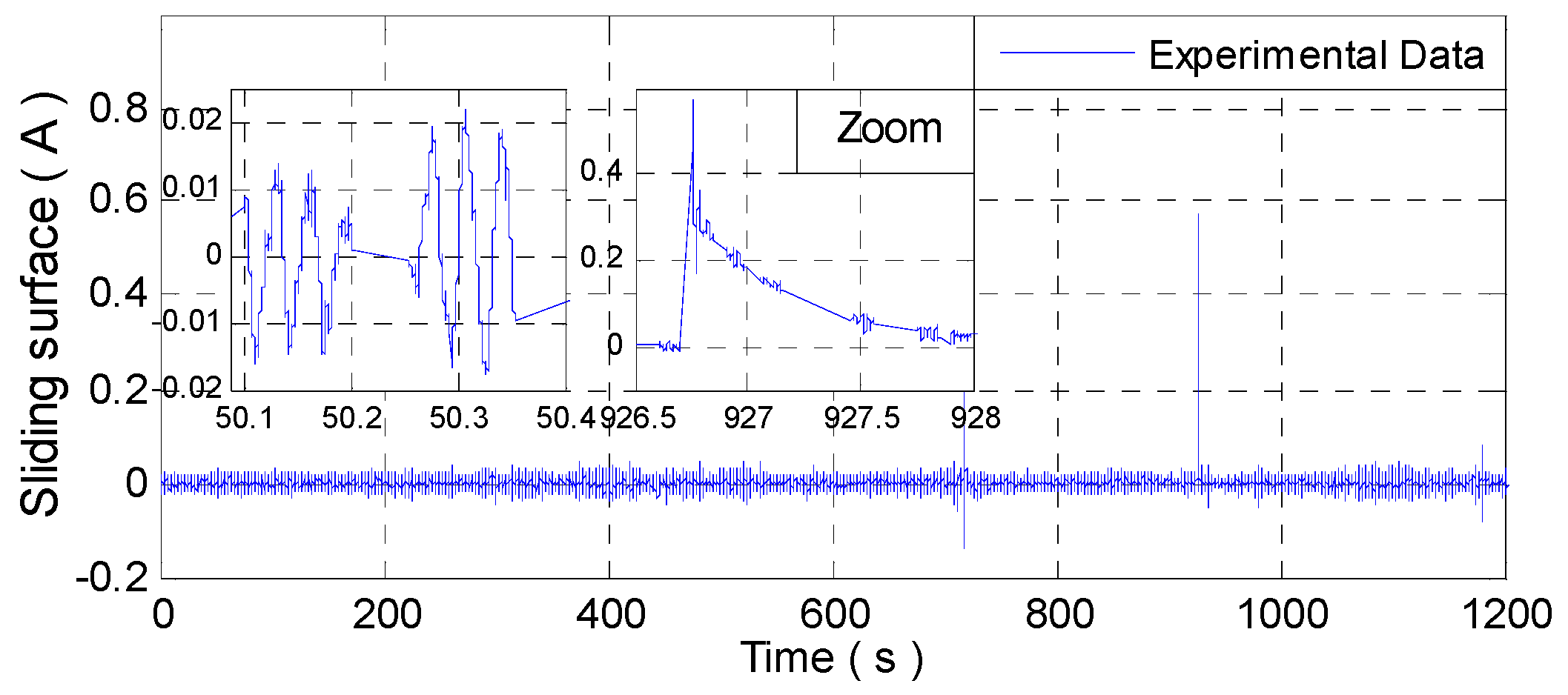
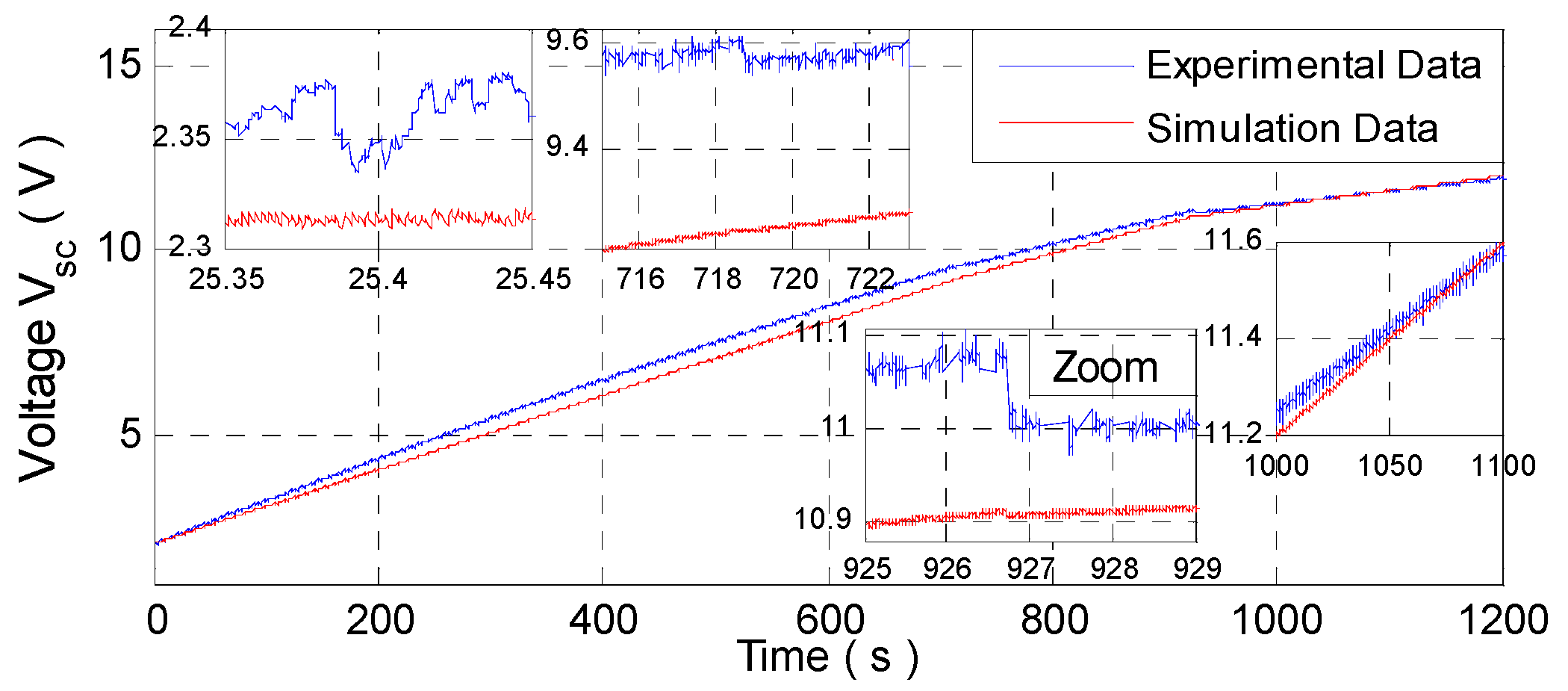
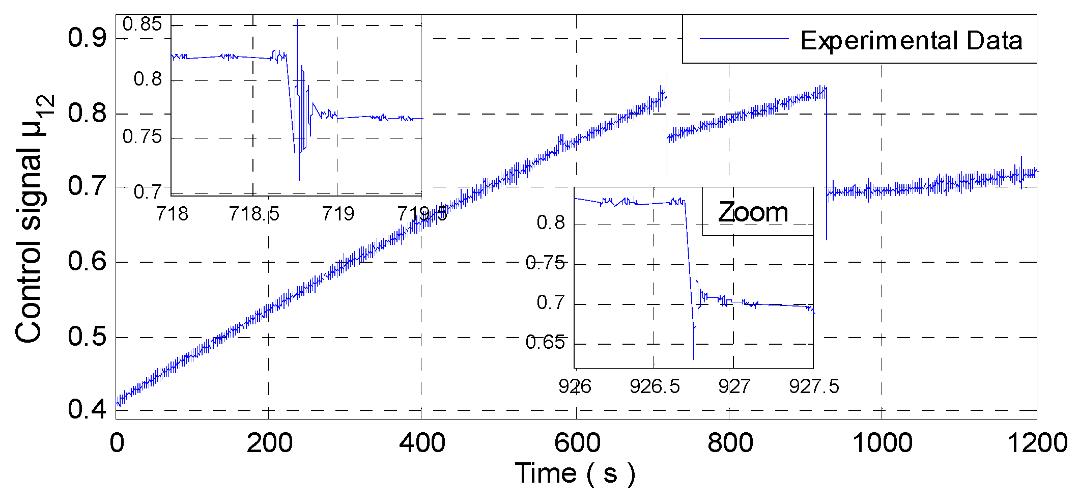
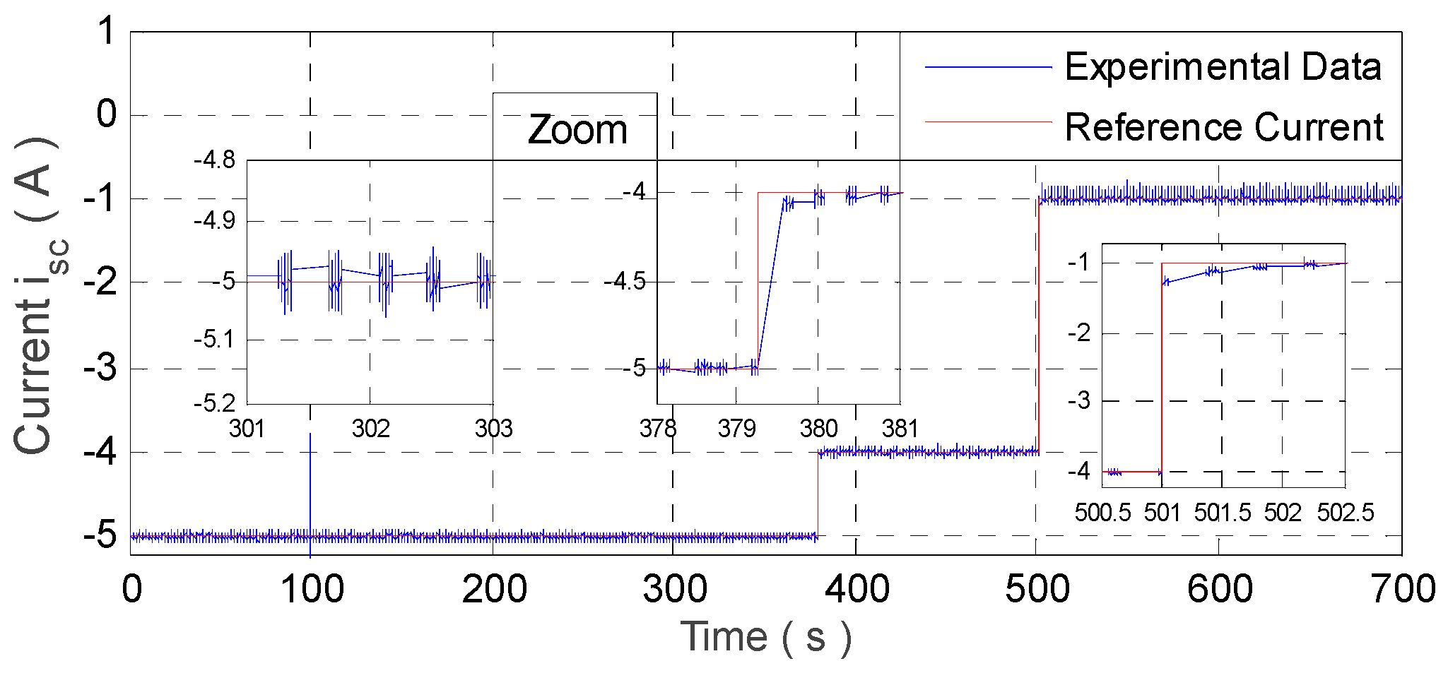
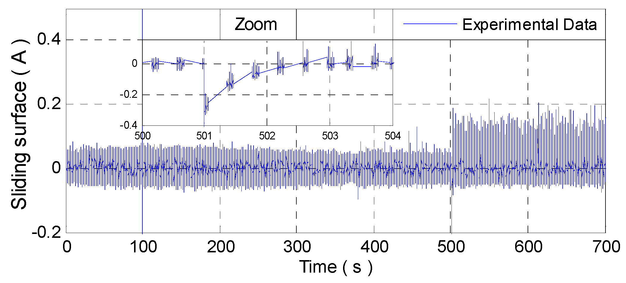
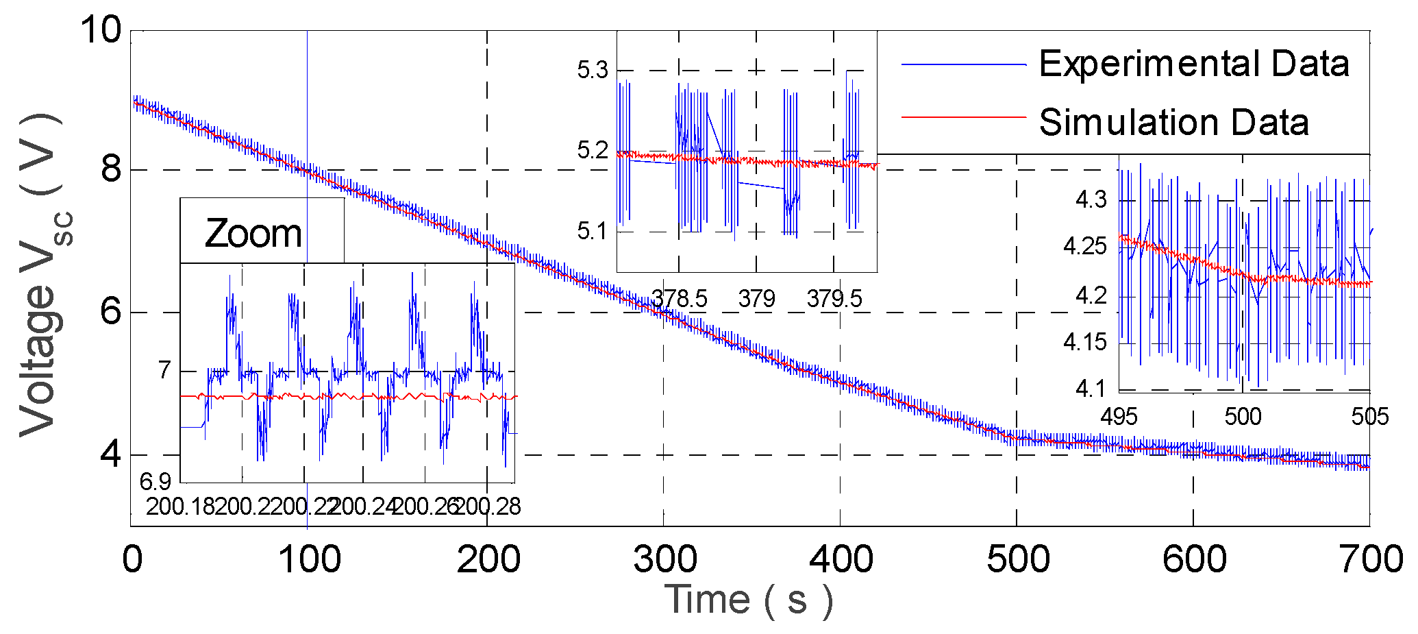
4.4. Figures and Experimental Results
- -
- The simulation and experimental results responded perfectly to the theoretical approach (ISMC, integral sliding mode control) used in this paper.
- -
- The results of the simulation of the reversible buck–boost current converter on Matlab®/Simulink® were identical to the experimental results that were taken by the dSPACE DS1202 card.
- ▪
- Charging mode of SC (Buck operation, k = 0)
- ▪
- Discharging mode of SC (Boost operation, k = 1)
5. Conclusions
Author Contributions
Funding
Acknowledgments
Conflicts of Interest
References
- Chan, C.C. The State of the Art of Electric, Hybrid, and Fuel Cell Vehicles. Proc. IEEE 2007, 95, 704–718. [Google Scholar] [CrossRef]
- Momoh, O.D.; Omoigui, M.O. An overview of hybrid electric vehicle technology. In Proceedings of the IEEE Vehicle Power and Propulsion Conference, VPPC09, Dearborn, MI, USA, 7–10 September 2009; pp. 1286–1292. [Google Scholar]
- Jung, H. Fuel Economy of Plug-In Hybrid Electric and Hybrid Electric Vehicles: Effects of Vehicle Weight, Hybridization Ratio and Ambient Temperature. World Electr. Veh. J. 2020, 11, 31. [Google Scholar] [CrossRef]
- Traube, J.; Lu, F.; Maksimović, D. Electric vehicle DC charger integrated within a photovoltaic power system. In Proceedings of the 2012 Twenty-Seventh Annual IEEE Applied Power Electronics Conference and Exposition (APEC), Orlando, FL, USA, 5–9 February 2012; Institute of Electrical and Electronics Engineers (IEEE): Piscataway, NJ, USA, 2012; pp. 352–358. [Google Scholar]
- Richardson, D.B. Electric Vehicles and the Electric Grid: A review of modeling approaches, Impacts, and renewable energy integration. Renew. Sustain. Energy Rev. 2013, 19, 247–254. [Google Scholar] [CrossRef]
- Zhang, M.; Fan, X. Review on the State of Charge Estimation Methods for Electric Vehicle Battery. World Electr. Veh. J. 2020, 11, 23. [Google Scholar] [CrossRef]
- Joos, G.; De Freige, M.; Dubois, M. Design and simulation of a fast charging station for PHEV/EV batteries. In Proceedings of the 2009 IEEE Electrical Power & Energy Conference (EPEC); Institute of Electrical and Electronics Engineers (IEEE): Piscataway, NJ, USA, 2010; pp. 1–5. [Google Scholar]
- Rajashekara, K. Hybrid Fuel-Cell Strategies for Clean Power Generation. IEEE Trans. Ind. Appl. 2005, 41, 682–689. [Google Scholar] [CrossRef]
- Pukrushpan, J.T.; Peng, H.; Stefanopoulou, A.G. Control-Oriented Modeling and Analysis for Automotive Fuel Cell Systems. J. Dyn. Syst. Meas. Control. 2004, 126, 14–25. [Google Scholar] [CrossRef]
- Pukrushpan, J.T.; Stefanopoulou, A.G.; Peng, H. Control of Fuel Cell Power Systems: Principles; Modeling; Analysis and Feedback Design; Springer-Verlag: London, UK, 2005. [Google Scholar]
- Boettner, D.D.; Paganelli, G.; Guezennec, Y.G.; Rizzoni, G.; Moran, M.J. Proton Exchange Membrane Fuel Cell System Model for Automotive Vehicle Simulation and Control. J. Energy Resour. Technol. 2002, 124, 20–27. [Google Scholar] [CrossRef]
- Emadi, A.; Rajashekara, K.; Williamson, S.; Lukic, S.M. Topological Overview of Hybrid Electric and Fuel Cell Vehicular Power System Architectures and Configurations. IEEE Trans. Veh. Technol. 2005, 54, 763–770. [Google Scholar] [CrossRef]
- Powers, W.F.; Nicastri, P.R. Automotive vehicle control challenges in the 21st century. Control. Eng. Pr. 2000, 8, 605–618. [Google Scholar] [CrossRef]
- Emadi, A.; Ehsani, M.; Miller, J.M. Vehicular Electric Power Systems; Marcel Dekker Inc.: New York, NY, USA, 2004. [Google Scholar]
- Burnett, M.B.; Borle, L.J. A power system combining batteries and supercapacitors in a solar/hydrogen hybrid electric vehicle. In Proceedings of the 2005 IEEE Vehicle Power and Propulsion Conference; Institute of Electrical and Electronics Engineers (IEEE): Piscataway, NJ, USA, 2005; pp. 7–9. [Google Scholar]
- Khaligh, A.; Li, Z. Battery, Ultracapacitor, Fuel Cell, and Hybrid Energy Storage Systems for Electric, Hybrid Electric, Fuel Cell, and Plug-In Hybrid Electric Vehicles: State of the Art. IEEE Trans. Veh. Technol. 2010, 59, 2806–2814. [Google Scholar] [CrossRef]
- Song, Z.; Hou, J.; Hofmann, H.; Li, J.; Ouyang, M. Sliding-mode and Lyapunov function-based control for battery/supercapacitor hybrid energy storage system used in electric vehicles. Energy 2017, 122, 601–612. [Google Scholar] [CrossRef]
- Xu, D.; Liu, Q.; Yan, W.; Yang, W. Adaptive Terminal Sliding Mode Control for Hybrid Energy Storage Systems of Fuel Cell, Battery and Supercapacitor. IEEE Access 2019, 7, 29295–29303. [Google Scholar] [CrossRef]
- Song, H.; Zhang, T.; Zhang, G.; Lu, C. Robust dynamic surface control of nonlinear systems with prescribed performance. Nonlinear Dyn. 2013, 76, 599–608. [Google Scholar] [CrossRef]
- Liu, Q.; Xu, D.; Jiang, B.; Ren, Y. Prescribed-Performance-Based Adaptive Control for Hybrid Energy Storage Systems of Battery and Supercapacitor in Electric Vehicles. Int. J. Innov. Comput. Inform. Contr. 2020, 16, 571–583. [Google Scholar]
- De Melo, R.R.; Tofoli, F.L.; Daher, S.; Antunes, F.L.M. Interleaved bidirectional DC–DC converter for electric vehicle applications based on multiple energy storage devices. Electr. Eng. 2020, 1–13. [Google Scholar] [CrossRef]
- Ortuzar, M.; Moreno, J.; Dixon, J. Ultracapacitor-Based Auxiliary Energy System for an Electric Vehicle: Implementation and Evaluation. IEEE Trans. Ind. Electron. 2007, 54, 2147–2156. [Google Scholar] [CrossRef]
- Belhaj, F.; El Fadil, H.; Rachid, A.; Lassioui, A.; Gaouzi, K.; Giri, F. Output feedback control of supercapacitors parallel charging system for EV applications: Theoretical design and experimental validation. Int. J. Adapt. Control. Signal Process. 2019, 33, 1374–1394. [Google Scholar] [CrossRef]
- Ben Saad, K.; Sahbani, A.; Benrejeb, M. Sliding Mode Control and Fuzzy Sliding Mode Control for DC–DC Converters. In Sliding Mode Control; IntechOpen: London, UK, 2011. [Google Scholar]
- Tahri, F. Contribution à l’étude et la commande du convertisseur CC-CC. Ph.D. Thesis, UniversitéUSTO-MB, Bir El Djir, Algeria, September 2014. [Google Scholar]
- El Fadil, H.; Giri, F.; Ouadi, H. Adaptive sliding mode control of PWM boost DC-DC converters. In Proceedings of 2006 IEEE Conference on Computer Aided Control System Design, 2006 IEEE International Conference on Control Applications, 2006 IEEE International Symposium on Intelligent Control; IEEE: Munich, Germany, 2006; pp. 3151–3156. [Google Scholar]
- El Fadil, H.; Giri, F.; Guerrero, J.M.; Tahri, A. Modeling and Nonlinear Control of a Fuel Cell/Supercapacitor Hybrid Energy Storage System for Electric Vehicles. IEEE Trans. Veh. Technol. 2014, 63, 3011–3018. [Google Scholar] [CrossRef]
- Li, H.; Yu, J.Y.; Zhang, Y.A. Stable Nonlinear Control Allocation for Aircraft with Multiple Control Effectors. Appl. Mech. Mater. 2011, 138, 404–409. [Google Scholar] [CrossRef]
- dSPACE. dSPACE Catalog 2019. Available online: https://www.dspace.com/fr/fra/home/medien/product_info/catalog_contents.cfm (accessed on 15 May 2019).
- dSPACE. dSPACE Magazine 1/2020. Available online: https://www.dspace.com/fr/fra/home/medien/dspace_news.cfm (accessed on 7 March 2020).


| Parameter | Value |
|---|---|
| Inductance L | 4 mH |
| Inductances ESR, RL | 620 mΩ |
| Supercapacitor, Csc | 500 F |
| Supercapacitor ESR, Rsc | 2.1 mΩ |
| Switching frequency, fsimulation Switching frequency, fexperimental | 25 kHz 15 kHz |
© 2020 by the authors. Licensee MDPI, Basel, Switzerland. This article is an open access article distributed under the terms and conditions of the Creative Commons Attribution (CC BY) license (http://creativecommons.org/licenses/by/4.0/).
Share and Cite
El Idrissi, Z.; El Fadil, H.; Belhaj, F.Z.; Lassioui, A.; Oulcaid, M.; Gaouzi, K. Theoretical Design and Experimental Validation of a Nonlinear Controller for Energy Storage System Used in HEV. World Electr. Veh. J. 2020, 11, 49. https://doi.org/10.3390/wevj11030049
El Idrissi Z, El Fadil H, Belhaj FZ, Lassioui A, Oulcaid M, Gaouzi K. Theoretical Design and Experimental Validation of a Nonlinear Controller for Energy Storage System Used in HEV. World Electric Vehicle Journal. 2020; 11(3):49. https://doi.org/10.3390/wevj11030049
Chicago/Turabian StyleEl Idrissi, Zakariae, Hassan El Fadil, Fatima Zahra Belhaj, Abdellah Lassioui, Mostapha Oulcaid, and Khawla Gaouzi. 2020. "Theoretical Design and Experimental Validation of a Nonlinear Controller for Energy Storage System Used in HEV" World Electric Vehicle Journal 11, no. 3: 49. https://doi.org/10.3390/wevj11030049
APA StyleEl Idrissi, Z., El Fadil, H., Belhaj, F. Z., Lassioui, A., Oulcaid, M., & Gaouzi, K. (2020). Theoretical Design and Experimental Validation of a Nonlinear Controller for Energy Storage System Used in HEV. World Electric Vehicle Journal, 11(3), 49. https://doi.org/10.3390/wevj11030049