Article

Primary Frequency Response Improvement in Interconnected Power Systems Using Electric Vehicle Virtual Power Plants

1
Department of Electrical Power Engineering, Faculty of Mechanical and Electrical Engineering, Tishreen University, Lattakia 2230, Syria
2
Department of Management Innovation Systems, University of Salerno, 84084 Salerno, Italy
3
Department of Engineering, University of Sannio, 82100 Benevento, Italy
4
Department of Electrical Engineering and Information Technology, University of Naples Federico II, Via Claudio 21, 80125 Napoli, Italy
5
Department of Power Systems, Polytechnic University of Bucharest, 060042 Bucharest, Romania
*
Author to whom correspondence should be addressed.
World Electr. Veh. J. 2020, 11(2), 40; https://doi.org/10.3390/wevj11020040
Submission received: 21 April 2020 / Revised: 5 May 2020 / Accepted: 14 May 2020 / Published: 16 May 2020
(This article belongs to the Special Issue Power System and Energy Management of Hybrid Electric Vehicles)

Abstract

:
The smart grid concept enables demand-side management, including electric vehicles (EVs). Thus way, some ancillary services can be provided in order to improve the power system stability, reliability, and security. The high penetration level of renewable energy resources causes some problems to independent system operators, such as lack of primary reserve and active power balance problems. Nowadays, many countries are encouraging the use of EVs which provide a good chance to utilize them as a virtual power plant (VPP) in order to contribute to frequency event. This paper proposes a new control method to use EV as VPP for providing primary reserve in smart grids. The primary frequency reserve helps the power system operator to intercept the frequency decline and to improve the frequency response of the whole system. The proposed method calculates the electric vehicles’ primary reserve based on EVs’ information, such as the state of charge (SOC), the arriving time and the vehicle’s departure time. The effectiveness of the proposed scheme is verified by several simulation scenarios on a real-world modern power system with different generating units, such as conventional power plants, renewable energy resources, and electric vehicles.

1. Introduction

Power systems are the power of economic advancement and human intelligence that need to be well-operated and secured. Prosperous economic leads to a huge demand of electricity power due to high industrial and commercial consumption [1]. To provide sustainable energy for the large electricity demand, many countries have increased the penetration level of renewable energy resources in their power systems due to the environmental concerns and fossil energy risks. Such high penetration of renewables provides new opportunities and challenges to modern power system operator [2]. The most important challenge of renewable energy resources is their uncertainty, and as consequence this challenge makes problems in the frequency and active power balancing control [3]. Recently, some efforts have been made for investigating the ability of renewable energy sources in providing some ancillary services such as primary and secondary reserves [3,4].
The frequency deviation is mainly caused by an imbalance between active power generation and demand. From the viewpoint of the power system security and stability, the power system frequency should be maintained in permissible ranges near to the rated value. In power systems, the frequency control is defined as the ability to return the frequency to its nominal value by maintaining the active power balance between the generation and demand [5]. To keep the balance between the generation and the demand and to maintain the frequency in acceptable rage, an active power is required to be activated quickly which called active power reserve. In conventional power systems, the active power reserve is usually planned to be available form the generation side, i.e., synchronous generators, which means that the generator can increase/decrease its active power production quickly. For increasing its active power generation, a portion of the generation capacity is reserved for contingency situations which called spinning reserve. However, in recent years, new studies started focusing on providing the active power reserve from the demand-side using demand response programs and electric vehicles contributions to power system frequency control methods. Based on the activation time of the active power reserve, the frequency control is usually divided into three control levels, i.e., primary, secondary and tertiary frequency control loops. Primary frequency control is very fast and tries to intercept the frequency decline before triggering the protection relays. Secondary frequency control or load frequency control (LFC) activates the secondary reserve after primary reserve in 30 s to 30 min, which tries to bring the frequency to its rated level by removing the steady state errors in the frequency. Finally, the tertiary reserve is activated manually by re-dispatching generating units considering some economic objectives, in which is mainly used after a large disturbances or large power plant outage [6].
Nowadays, there are great efforts from researchers to enhance the frequency stability in power systems especially due load fluctuations and renewable power generation variations. Load frequency techniques are used for controlling the frequency changes due to load fluctuations. In [7], wind driven optimization (WDO) technique has been used for tuning the controller parameters to achieve optimal LFC in modern power systems. Likewise, many-objective optimization technique has been proposed in [8] for modern power systems. It has been found that the performance of many-objective optimization techniques have better performance compared to multi-objective optimization methods. In [9], the impact of sensor faults and measurement errors on the frequency control performance in power systems has been well-studied. Recently, dynamic state estimation methods, especially unknown input observers, have been proposed for controlling the frequency in smart grids and modern power systems [10,11,12,13]. Wide-area monitoring systems are also utilized for improving frequency stability in power systems by using them in the control and protection schemes [14,15,16]. Readers interested in frequency control and protection systems are referred to the latest reviews in [17,18].
The demand side can provide more reliable and less expensive primary and secondary reserves. However, different appliances, such as air conditioners, freezers, refrigerators, and water heaters can provide primary frequency control with the minimum inconvenience to the customers. Electric vehicles (EVs) are another type of demand-side appliances that can contribute to providing primary and secondary reserves by well-controlling their charging power [19]. Nowadays, EVs have gained a considerable attention from academic and industrial communities thanks to their capability of providing reliable, secure, environmentally friendly, and less expensive ancillary services [20]. By using EVs as a virtual power plant (VPP), the high expensive reserves from conventional units such as hydro and thermal units can be avoided. Ref. [21] shows that electric vehicles can effectively improve frequency stability and security in micro-grids and isolated power systems. An aggregation-based dynamic model of plug-in EVs for primary frequency control in Spanish power system has been suggested in [22]. Ref. [23] proposes a new EVs demand estimation tool in Great Britain’s power system for the year 2020. To calculate the primary reserve from all EVs integrated to the electricity network, a new grouping method has been proposed in [24]. Likewise, a simple EVs control approach based on suddenly disconnection of all plug-in EVs from the power system following a large disturbance is proposed and tested on Great Britain’s power system in [23]. Adjusting EVs’ droop coefficient according to EVs’ energy in order to achieve the best control is suggested in [25].
Despite the technical virtual power plant, distributed generation (DG) will be able to contribute in improving the network security and the management of the system, such as frequency control improvement. On the other hand, technical VPPs try to optimize control and coordination, as well as the system operation [26]. In [27], an architecture and its communication requirements of an electric vehicle-based vehicle-to-grid integrating virtual power plants is described. The communication between EVs, energy generators, grid resources and power grid is described for control purposes. Three ways of integrating electric vehicles in the form of virtual power plants have been suggested in [28,29]. Such ways are essentially based on control structures, components and methods of integration. In [30], a method of frequency control by plug-in hybrid electric vehicle as a VPP has been suggested for future power systems.
This paper proposes a new technique for the participation of EVs in the primary frequency response improvement in power systems. The proposed technique is based on the control of all EVs connected to the grid as a VPP. In this paper, the electric vehicle primary reserve is determined by using the EV information such as initial state of charge, arriving time, the required state of charge for the next trip, and the temperature time. Then, based on the determined primary reserve, a new primary frequency response model suitable for dynamic studies is proposed. The parameters of the suggested dynamic model are calculated online based on the proposed EVs aggregation method. The proposed model has several advantages including (i) its ability for assessing the frequency security in power systems, (ii) its capability to be used as a base for determining the required reserve in modern power systems, and (iii) its ability for online monitoring the frequency stability of modern power systems. The main contributions of the paper are:
  • Proposing of electric vehicle aggregator for frequency studies.
  • Suggesting electric vehicle contribution in the provision of ancillary services for smart grids.
  • Proposing virtual power plant based on the available electric vehicle stored reserves.
  • Improving the primary frequency response in power systems using vehicle-to-grid technique.
  • Suggesting a simple and accurate frequency response model for future power system studies.
  • Testing the proposed method on real-world power system.
The rest of the paper is organized as follows. Section 2 introduces a review study on VPP and frequency control. The online electric vehicle VPP based primary reserve is presented in Section 3. The dynamic model of EV for primary frequency response studies is introduced in Section 4. Section 5 presents the studied power system details and information. The simulation results and simulation scenarios are presented in Section 6, while Section 7 concludes.

2. Primary Frequency Control

2.1. Virtual Power Plant Overview

Virtual power plants can be divided into commercial and technical VPPs based on their electricity market. The commercial VPPs participate in electricity market to maximize their profit while the technical VPPs do not participate in electricity market. In other words, commercial VPPs try to optimize their profit and the technical VPPs try to optimize their participation in power system control [28].
In literature, many types of VPPs have been proposed which are, [31,32]:
  • Market-Based Virtual Power Plant (MBVPP)
  • Generic Virtual Power Plant (GVPP)
  • Commercial Virtual Power Plant (CVPP)
  • Technical Virtual Power Plant (TVPP)
  • Environmental Virtual Power Plant (EVPP)
  • Electric Vehicle Virtual Power Plant (EV-VPP)
To cover the control strategies of the above category of VPPs, there are three different approaches that can be used to control all components of virtual power plant:
  • Centralized Controlled Virtual Power Plant (CCVPP)
  • Distributed Controlled Virtual Power Plant (DCVPP)
  • Fully Distributed Controlled Virtual Power Plant (FDCVPP)
In this paper, EV-VPP is suggested to provide primary reserve for power system operators. Furthemore, the centralized controlled virtual power plant as an online control is adopted.

2.2. Frequency Control Overview

The frequency control approach in interconnected power systems basically consists of primary and secondary control loops. Primary and secondary frequency control loops in modern power systems are depicted in Figure 1. This model consists of: (1) transfer function between the power mismatch and the power system frequency deviation, (2) the demand and generation unit blocks, (3) EV dynamic model for frequency studies, and (4) the load frequency control center (LFC). In this paper, the generation unit blocks are divided into two types: (a) conventional power plants which contribute to frequency event by providing primary and secondary reserves, and (b) non-dispatchable units that cannot provide primary reserve such as wind turbines and solar panels.
In practice, the mismatch between the total generated active power and the active power demand causes the frequency deviation/oscillation, which depends on the total inertia amount of all synchronous machines in the system (H) and the frequency sensitivity load-damping (D) [5]. The dynamic model of EV for frequency studies depicted in Figure 1 will be described in Section 4.

3. Online EV-Based VPP for Primary Reserve

3.1. Multi Agent EV Based Online VPP

To achieve the online operation of VPPs, a bidirectional communication between each individual EV and power system operator is required. This paper assumes that a two-way communication based on EV multi agent system is used. A multi agent system can be defined as a group of autonomous, interacting agents sharing a common environment. To practically realize the multi agent control schemes, smart sensor network and actuators are in the demand [33]. In our study, a multi agent system which consists of three control levels, is adopted for achieving EV-VPP. The first level consists of all individual EV agents, where each individual EV is called EV agent. The second level refers to a concentrate agent and the third level consists of a VPP agent only. The VPP agent is in charge of determining the primary reserve from EVs in all power system rejoin. First, each individual EV sends its information to the concentrate agent in its area, then the concentrate agents sum up primary reserve and send it to the VPP agent. The aforementioned process of primary reserve calculation in power system is performed in each control step time. The VPP agent calculates the primary reserve and negotiates it with the system operator based on the ancillary services electricity market negotiations. To calculate the available primary reserve, some information, e.g., arriving time, state of charge (SOC), required SOC for the next trip, current SOC, departure time, battery capacity, EV owners’ decision is required.

3.2. Primary Reserve Calculation

To calculate the primary reserve in VPP agent for the next 5 min, a new grouping strategy is suggested and implemented in this paper. EVs are divided into three different groups. Group 1 consists of all disconnected EVs and connected EVs with special constraints such as SOC level and owners’ decision. EVs with SOC below 10% or more than 90% cannot contribute to primary frequency response due to battery time life constraints [24]. Likewise, EVs without owners’ permission cannot participate in primary frequency control because VPP operator cannot force EVs owners. On the other hand, Group 2 consists of all charging EV with SOC between 10% and 90%. EVs in this group participate in frequency control by stopping their charging first, then by injecting their power back into the grid. Group 3 consists of all idle EVs connected to power system. The EVs in this group contribute to primary frequency response by injecting their power into the grid. The aforementioned grouping process is arranged according to the following constraints:
  • Group 1 constraints:
    If {Connected EV to the grid status: NO) Or (Connected EV to the grid status: YES; and ( 10 % S O C 90 % )}, Then put EV in Group 1.
  • Group 2 constraints:
    If {Connected EV to the grid status: YES; and ( 10 % S O C 90 % )} Then place EV in Group 2.
  • Group 3 constraints:
    If Connected EV to the grid status: YES; and (Charging status: idle), Then place EV in Group 3.
The primary reserve from each EV group in power systems is determined as follows:
  • Group 1 does not provide any primary reserve to the power system.
  • EVs in Group 2 provide primary reserve by stopping their charge and injecting their power back into grid as follows
    p 1 r g r 2 = 2 . N e v g r 2 . P e v max
    where p 1 r g r 2 , N e v g r 2 , and P e v max are the primary reserve from all EVs in group 2, the number of EVs in group 2, and the maximum EV charging power rate in [kW], respectively. It is worth mentioning that the number 2 in Equation (1) is added because the electric vehicles in this group participate to frequency control not only by stopping their charging power, but also by injecting some of the stored electric energy in their batteries into the electric power grid.
  • EVs in group 3 provide primary reserve for primary frequency control by discharging their power only as follows
    p 1 r g r 3 = N e v g r 3 . P e v max
    where p 1 r g r 3 , and N e v g r 3 are the primary reserve from EVs in group 3 and the number of EVs in group 3, respectively.
According to the above new grouping strategy, the total primary reserve in [MW] of all aggregation groups is calculated as follows
p e v 1 r = 2 . N e v g r 2 + N e v g r 3 . P e v max

4. EV Dynamic Model for Frequency Evaluation

The MERGE project of EU countries identifies four EV types for Europe market [24]. The different EVs types are L7e, M1, N1, and N2 [24]. Based on the database in the MERGE project, the EV types with their battery information of each EV type are represented in Table 1.
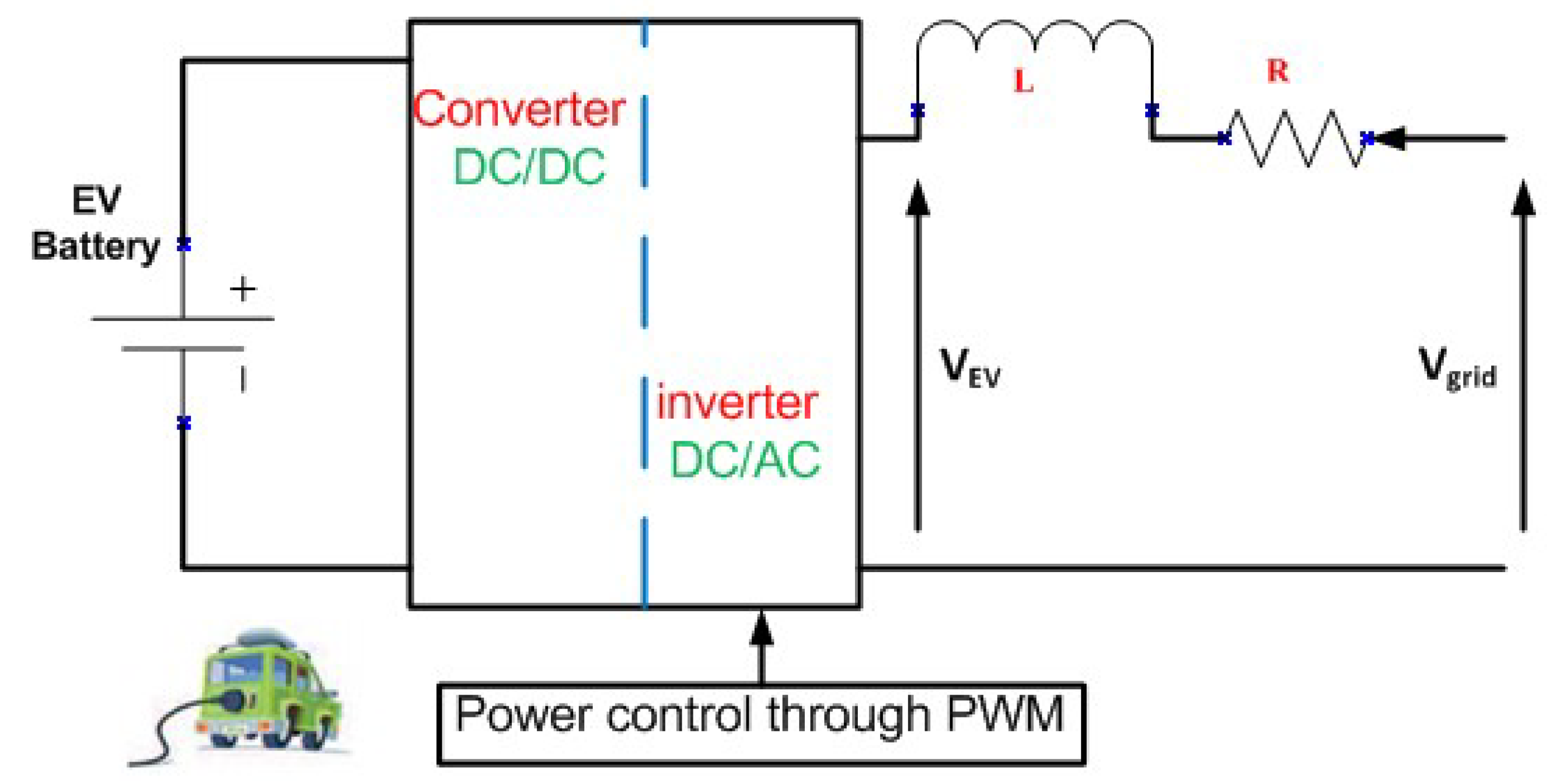
To obtain the EV dynamic response model, the related EV battery charger model is investigated. Figure 2 shows the electrical circuit of EV battery charger model which it consists of DC-DC converter and DC-AC inverter with small inductor (L) resistance (R) [23]. From Figure 2, the voltage and current equations are given as follows [34]:
V g r i d = V e v + V d r o p
V g r i d = V e v + L d i d t + R r . i
where V g r i d , V e v , V d r o p , and i are the power system network voltage, EV battery voltage, voltage losses in R and L, and the current between the inverter and the grid, respectively.
The active power exchanged between the grid and the EV battery would be presented by a differential equation. Therefore, the frequency model of EVs is modeled by using first order lag function with EV time constant T e v . The EV time constant can be calculated from Equation (5) as follows:
T e v = L R r
In power system frequency studies, EV can be modeled by a first order transfer function:
G ( s ) = 1 1 + s . T e v
T e v is set to 0.05 s in this paper. However, the EV time constant can be used as a variable number between 35 ms and 100 ms [23,35]. The aggregate model of all EVs available in the system can be modeled as shown in Figure 3. Basically, the primary frequency control consists of adjusted frequency droop coefficient R which depends on primary reserve from EV and frequency dead-band with upper and lower power limits. The dynamic function block of primary frequency control of EV is shown in Figure 3.

5. The Case Study System

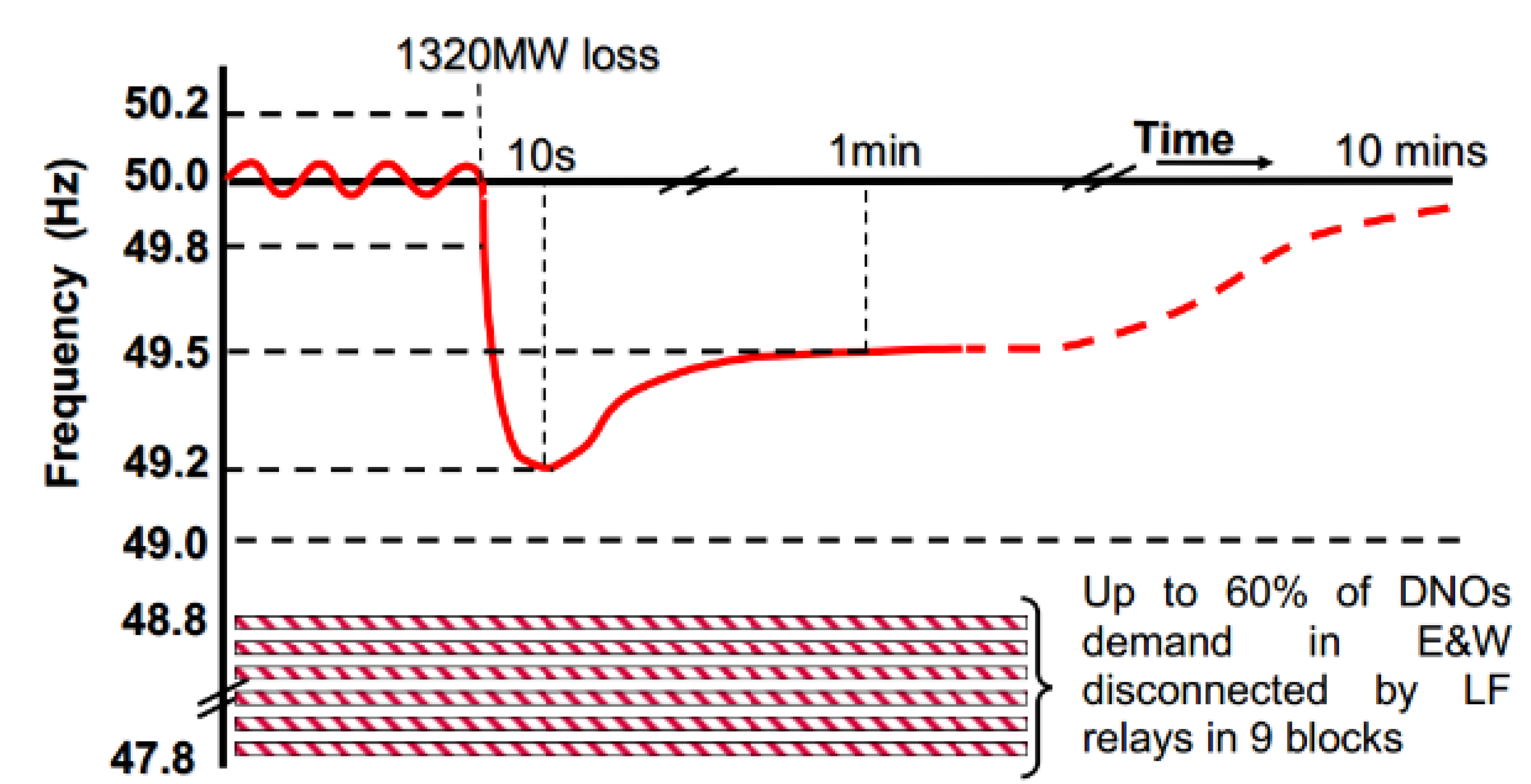
In this research, Great Britain’s power system is selected for simulation study due to availability of required information and parameters. Great Britain’s power system consists of conventional power plants with high penetration level of wind energy resources. This system is designed to accept steady state frequency deviation less than 0.5 Hz. Great Britain’s system can accept the most credible loss of 1320 MW of generation with maximum frequency nadir 49.2 Hz and restoration time 1 min to steady state frequency as shown in Figure 4 [28].
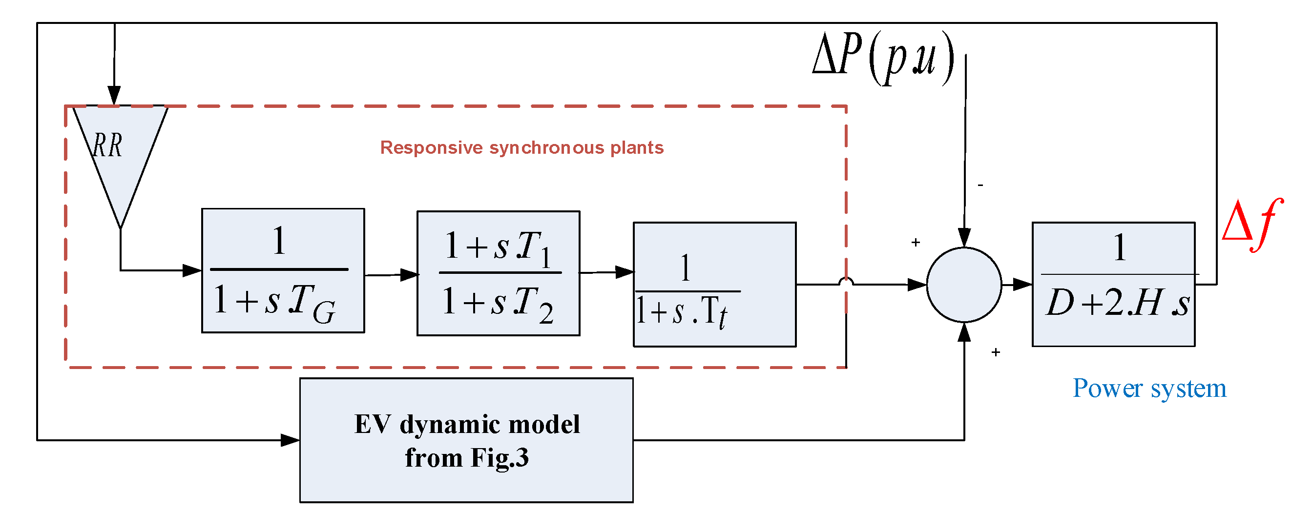
The MERGE project provides a statistical estimation of EVs penetration in Great Britain’s power system in 2020. The number of each type of EVs for year 2020 is estimated as follows: 8281 EVs of L7e, 486,341 EVs of M1, 55576 EVs of N1, and 5558 EVs of N2. The studied dynamic model of Great Britain’s system with EVs is shown in Figure 5. For Great Britain’s power system, H was calculated as 4.44 s which was obtained from [23]. The damping constant was set to 1.1 and the inverse of the total droop coefficient was set to −11. Furthemore, in this simulation study, the time constant of governor actuator ( T G ), the constant times of led lag transfer function ( T 1 , T 2 ), and turbine constant time ( T T ) were set to 0.2, 2, 12, 0.3, respectively. The aforementioned parameters of simplified frequency response model of Great Britain’s power system were calculated based on contingency event that occurred on 27 May 2008 [28]. The data are given in Appendix A, the primary frequency response in Great Britain’s power system with EV penetration level is studied and the results are given in the next section. The details of the dynamic model of EV are presented in previous section and the dynamic model of Great Britain’s power system with EVs is used as shown in Figure 1.

6. Simulations and Discussions

The simulation is performed by using MATLAB/SIMULINK environment and the power system parameters shown in the Appendix. The simulation study is divided into two scenarios: (a) in the first scenario, the impact of the EV reserve control on the frequency is investigated, in the second scenario (b) primary frequency response and the impact of EVs into conventional power plant response are studied.
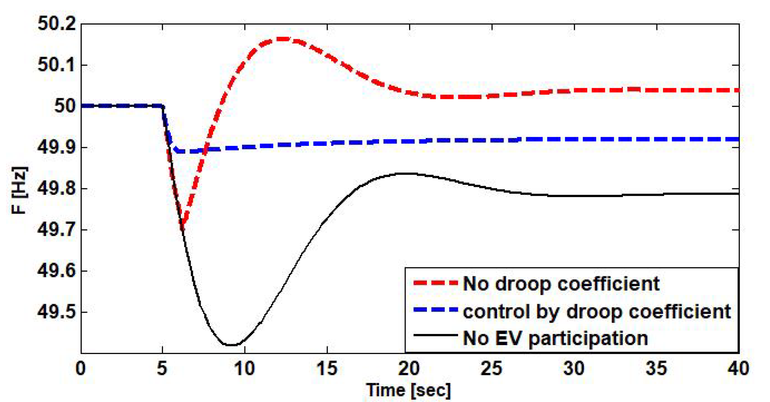
To investigate the proposed primary reserve from EV in Section 3, the proposed EV primary reserve control is compared to the proposed method in [23]. Ref. [23] proposed to control EV without adjusted droop coefficient (R) by stopping EV charging power when frequency drop below 49.7 Hz instantly. The aforementioned method is implemented in Great Britain’s power system and compared with the proposed method in this paper by using fix droop coefficient for each individual EV. In this study the drop coefficient is set to 0.05. Figure 6 presents the frequency simulation result of this scenario and shows the superiority of the proposed control method. Without EVs participation, the frequency drops below 49.5 Hz, while the frequency nadir is above 49.85 Hz when the proposed method is used. In the contrast, the primary frequency response becomes worse when the proposed method in [23] is used. Controlling EV primary reserve without an adjusted droop coefficient may cause over-frequency response and, as a consequence, may lead to triggering over-frequency relay or generating the unit’s protection relay.
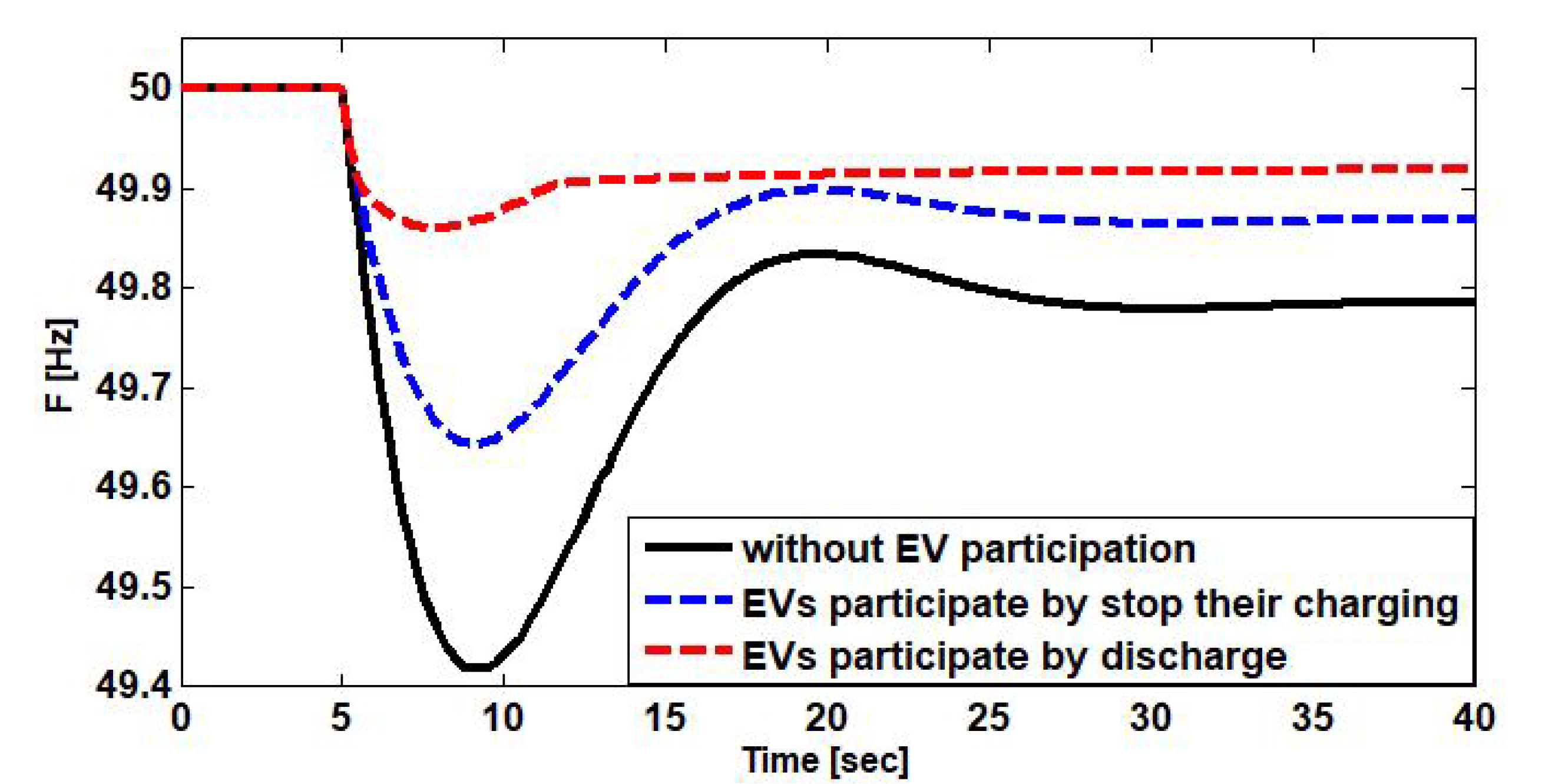
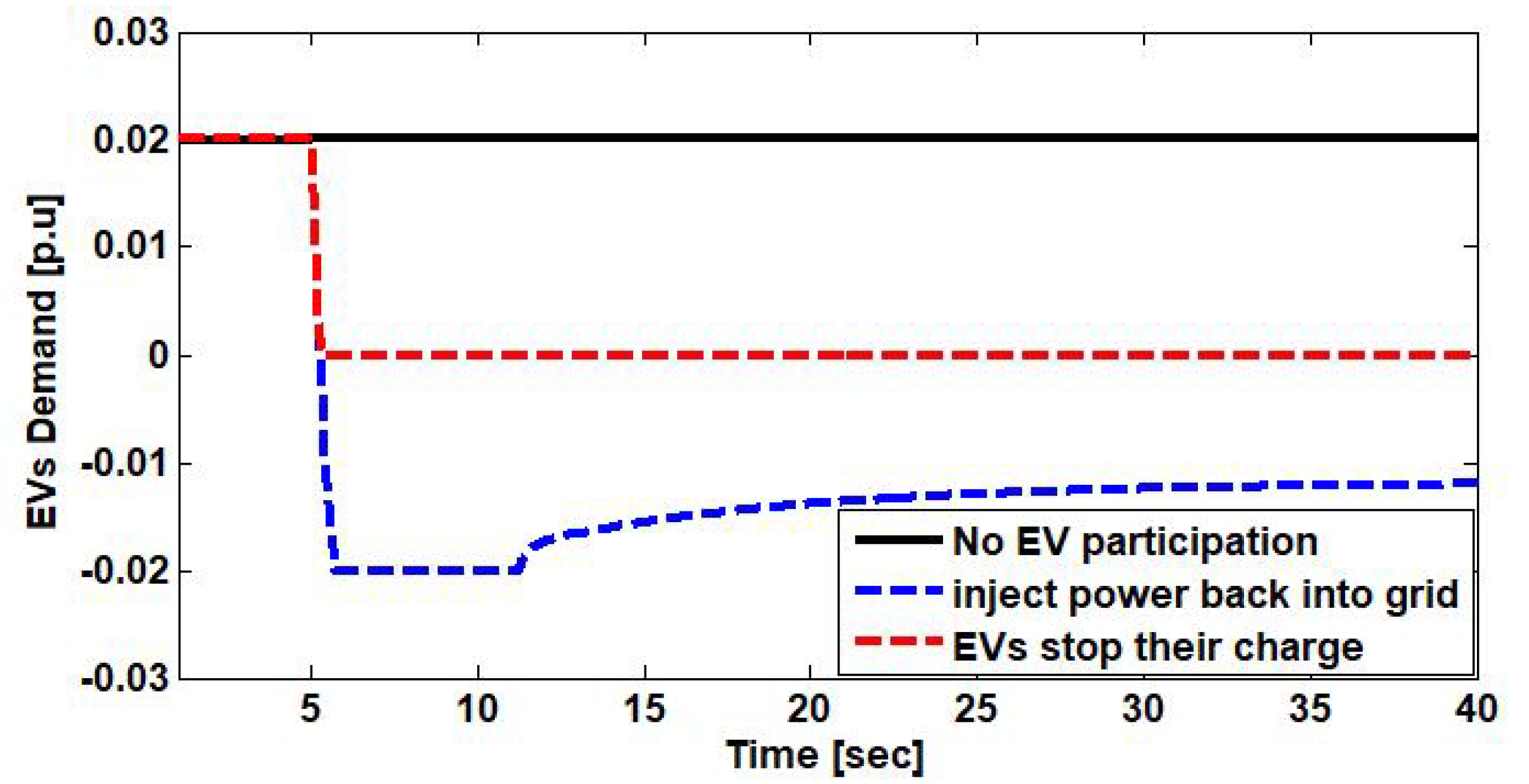
In scenario (b), primary frequency response in Great Britain’s power system is investigated. We assume that the EV demand when the contingency event is occurred is 700 MW (0.02 p.u). The contingency event in the studied power system is defined as 1800 MW generation loss [28]. Figure 7 shows the primary frequency response with and without EV participation. Without EV participation in the frequency event, the frequency nadir is less than 49.45 Hz while the frequency nadir is kept above 49.65 Hz when EVs participate by stopping their charging power. The frequency nadir is 49.88 Hz when EVs discharge their power into the grid. These results show that EVs provide a good opportunity to the grid operator to intercept frequency decline before triggering the under-frequency load shedding relays.
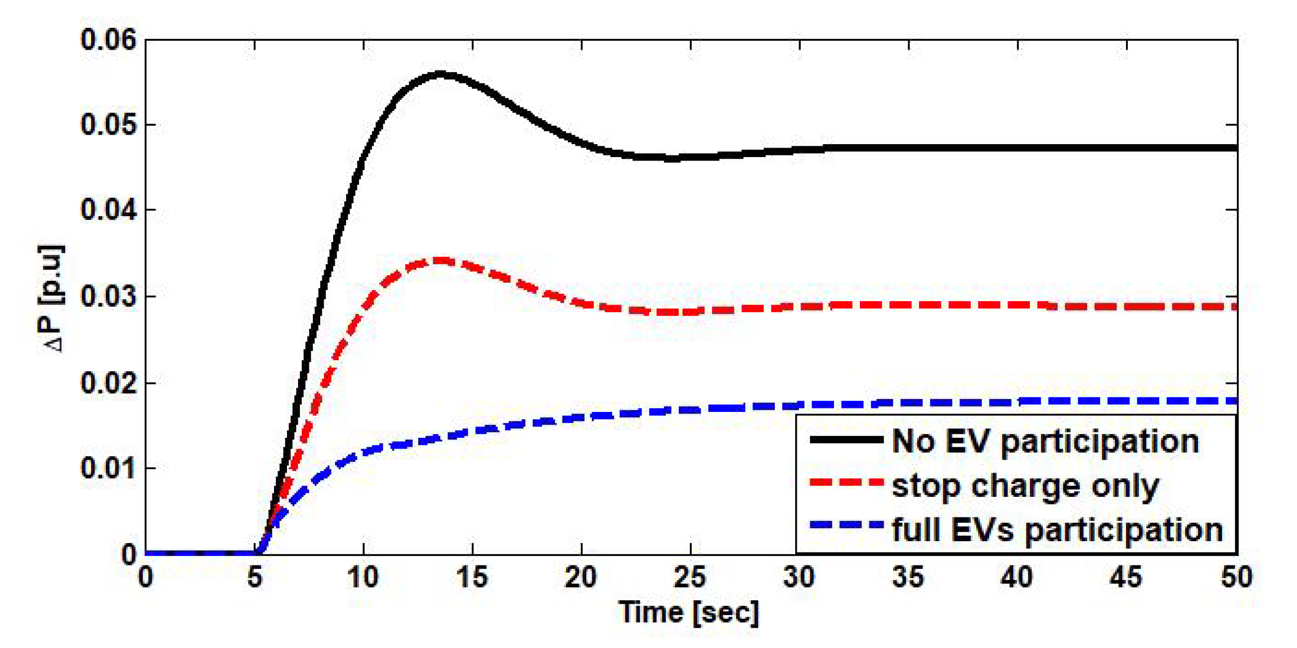
In the next step, the conventional power plant response with and without EV is investigated. Figure 8 shows the power plant output when Great Britain’s power system encounters 1800 MW generation loss. Without EV participation, the grid operator needs a primary reserve equal to 0.05 p.u during 10 s from conventional power plants while the required primary reserve from conventional power plants is 0.015 p.u when EVs contribute to the frequency event. The active power demand of all EVs and the EV demand response in the studied power system is shown in Figure 9, which depicts the behaviors of EVs in Groups 2 3. The above results verify the superiority of the proposed primary frequency response improvement based on the novel EV-based VPP technique.

7. Comparison Study

As aforementioned, the proposed primary frequency enhancement using EVs proposed in this paper has several advantages in comparison with other methods, such as the one in [23]. The method proposed in [23] uses EVs reserve by stopping the charging of all EVs when frequency drop below 49.7 Hz instantly. This means that the method in [23] does not consider any adjusted droop coefficient (R) which makes the frequency response worst in some some case, as shown in Figure 6. In our method, the drop coefficient is set to 0.05 and compared to the method in [23]. Figure 6 presents the frequency simulation result of this scenario and shows the superiority of the proposed control method. In the contrast, the primary frequency response becomes worse when the proposed method in [23] is used. Controlling the EV primary reserve without adjusted droop coefficient may cause over-frequency response and as consequence may lead to triggering over-frequency relay or generating unit’s protection relay.

8. Conclusions

This paper proposed a new technique for the participation of electric vehicles (EVs) in the primary frequency response in modern power systems. In particular, the primary frequency response with electric vehicles as a virtual power plant (EV-VPP) was investigated. A grouping strategy based on the EV’s information for VPP was used. The proposed technique was based on the online control of all EVs as a VPP. The electric vehicle primary reserve was determined by using the EVs’ information such as initial state of charge, arriving time, the required state of charge for the next trip, and the temperature time. Then, based on the determined primary reserve, a new primary frequency response model suitable for dynamic studies was proposed. The parameters of the suggested dynamic model were calculated online based on the proposed EVs aggregation method. The simulation results have highlighted several advantages of the proposed method including (i) its ability for assessing the frequency security in power systems, (ii) the capability to be used as a base to determine the required reserve in modern power systems, and (iii) its ability for online monitoring the frequency stability of modern power systems.

Author Contributions

All authors has worked on this paper. Conceptualization, H.H.A., P.S., M.T., R.I., and F.M.; methodology, H.H.A., P.S., M.T., R.I., and F.M.; software, H.H.A., P.S., M.T., R.I., and F.M.; validation, H.H.A., P.S., M.T., R.I., and F.M.; formal analysis, H.H.A., P.S., M.T., R.I., and F.M.; investigation, H.H.A., P.S., M.T., R.I., and F.M.; resources, H.H.A., P.S., M.T., R.I., and F.M.; data curation, H.H.A., P.S., M.T., R.I., and F.M.; writing–original draft preparation, H.H.A., P.S., M.T., R.I., and F.M.; writing–review and editing, H.H.A., P.S., M.T., R.I., and F.M.; visualization, H.H.A., P.S., M.T., R.I., and F.M.; supervision, H.H.A., P.S., M.T., R.I., and F.M.; project administration, H.H.A., P.S., M.T., R.I., and F.M.; funding acquisition, H.H.A., P.S., M.T., R.I., and F.M. All authors have read and agreed to the published version of the manuscript.

Funding

This research received no external funding.

Acknowledgments

Authors thank all colleagues for their great help for finalizing this paper.

Conflicts of Interest

The authors declare no conflict of interest.

Abbreviations

The following abbreviations are used in this manuscript:
EVElectric vehicle
VPPVirtual power plant
SOCState of charge
LFCLoad frequency control
DGDistributed generation
MBVPPMarket-Based Virtual Power Plant
GVPPGeneric Virtual Power Plant
CVPPCommercial Virtual Power Plant
TVPPTechnical Virtual Power Plant
EVPPEnvironmental Virtual Power Plant
EV-VPPElectric Vehicle Virtual Power Plant
CCVPPCentralized Controlled Virtual Power Plant
DCVPPDistributed Controlled Virtual Power Plant
FDCVPPFully Distributed Controlled Virtual Power Plant
HAll synchronous machines in the system
DThe frequency sensitivity load-damping

Appendix A. Parameters of the Studied Power System Model

H = 4.44 s, D = 1.1, T 1 = 2 s, T 2 = 12 s, T T = 0.3 s, T G = 0.2 s, R R = 1/( R e q ) = −11. T e v = 0.05 s, R e v = 0.05, upper and lower frequency dead band = 0 . 00002 H z .

References

  1. Lee, M.; Aslam, O.; Foster, B.; Kathan, D.; Kwok, J.; Medearis, L.; Palmer, R.; Sporborg, P.; Tita, M. Assessment of Demand Response and Advanced Metering; Technical Report; Federal Energy Regulatory Commission: Washington, DC, USA, 2013. [Google Scholar]
  2. Blaabjerg, F.; Teodorescu, R.; Liserre, M.; Timbus, A.V. Overview of control and grid synchronization for distributed power generation systems. IEEE Trans. Ind. Electr. 2006, 53, 1398–1409. [Google Scholar] [CrossRef] [Green Version]
  3. Gevorgian, V.; Zhang, Y.; Ela, E. Investigating the impacts of wind generation participation in interconnection frequency response. IEEE Trans. Sustain. Energy 2014, 6, 1004–1012. [Google Scholar] [CrossRef]
  4. Pearmine, R.; Song, Y.; Chebbo, A. Influence of wind turbine behaviour on the primary frequency control of the British transmission grid. IET Renew. Power Gener. 2007, 1, 142–150. [Google Scholar] [CrossRef]
  5. Kundur, P.; Balu, N.J.; Lauby, M.G. Power System Stability and Control; McGraw-Hill: New York, NY, USA, 1994; Volume 7. [Google Scholar]
  6. Bevrani, H.; Hiyama, T. Intelligent Automatic Generation Control; CRC Press: Boca Raton, FL, USA, 2016. [Google Scholar]
  7. Haes Alhelou, H.; Hamedani Golshan, M.E.; Hajiakbari Fini, M. Wind driven optimization algorithm application to load frequency control in interconnected power systems considering GRC and GDB nonlinearities. Electr. Power Compon. Syst. 2018, 46, 1223–1238. [Google Scholar] [CrossRef]
  8. Fini, M.H.; Yousefi, G.R.; Alhelou, H.H. Comparative study on the performance of many-objective and single-objective optimisation algorithms in tuning load frequency controllers of multi-area power systems. IET Gener. Trans. Distrib. 2016, 10, 2915–2923. [Google Scholar] [CrossRef]
  9. Alhelou, H.H.; Golshan, M.H.; Askari-Marnani, J. Robust sensor fault detection and isolation scheme for interconnected smart power systems in presence of RER and EVs using unknown input observer. Int. J. Electr. Power Energy Syst. 2018, 99, 682–694. [Google Scholar] [CrossRef]
  10. Alhelou, H.H.; Hamedani-Golshan, M.E.; Heydarian-Forushani, E.; Al-Sumaiti, A.S.; Siano, P. Decentralized fractional order control scheme for LFC of deregulated nonlinear power systems in presence of EVs and RER. In Proceedings of the 2018 International Conference on Smart Energy Systems and Technologies (SEST), Sevilla, Spain, 10–12 September 2018; pp. 1–6. [Google Scholar]
  11. Alhelou, H.H.; Golshan, M.E.H.; Hatziargyriou, N.D. A decentralized functional observer based optimal LFC considering unknown inputs, uncertainties, and cyber-attacks. IEEE Trans. Power Syst. 2019, 34, 4408–4417. [Google Scholar] [CrossRef]
  12. Alhelou, H.H.; Golshan, M.E.H.; Hatziargyriou, N.D. Deterministic dynamic state estimation-based optimal LFC for interconnected power systems using unknown input observer. IEEE Trans. Smart Grid 2019, 11, 1582–1592. [Google Scholar] [CrossRef]
  13. Alhelou, H.H.; Golshan, M. Decision-making-based optimal generation-side secondary-reserve scheduling and optimal LFC in deregulated interconnected power system. In Decision Making Applications in Modern Power Systems; Elsevier: Amsterdam, The Netherlands, 2020; pp. 269–299. [Google Scholar]
  14. Njenda, T.C.; Golshan, M.; Alhelou, H.H. WAMS based intelligent under frequency load shedding considering online disturbance estimation. In Proceedings of the 2018 Smart Grid Conference (SGC), Sanandaj, Iran, 28–29 November 2018; pp. 1–5. [Google Scholar]
  15. Haes Alhelou, H.; Hamedani Golshan, M.E.; Njenda, T.C.; Siano, P. Wams-based online disturbance estimation in interconnected power systems using disturbance observer. Appl. Sci. 2019, 9, 990. [Google Scholar] [CrossRef] [Green Version]
  16. Haes Alhelou, H.; Hamedani-Golshan, M.E.; Njenda, T.C.; Siano, P. Wide-area measurement system-based optimal multi-stage under-frequency load-shedding in interconnected smart power systems using evolutionary computing techniques. Appl. Sci. 2019, 9, 508. [Google Scholar] [CrossRef] [Green Version]
  17. Alhelou, H.H.; Hamedani-Golshan, M.E.; Zamani, R.; Heydarian-Forushani, E.; Siano, P. Challenges and opportunities of load frequency control in conventional, modern and future smart power systems: A comprehensive review. Energies 2018, 11, 2497. [Google Scholar] [CrossRef] [Green Version]
  18. Haes Alhelou, H.; Hamedani-Golshan, M.E.; Njenda, T.C.; Siano, P. A survey on power system blackout and cascading events: Research motivations and challenges. Energies 2019, 12, 682. [Google Scholar] [CrossRef] [Green Version]
  19. Baboli, P.T.; Moghaddam, M.P.; Fallahi, F. Utilizing electric vehicles on primary frequency control in smart power grids. In Proceedings of the International Conference Petroleum and Sustainable Develop, Dubai, United Arab Emirates, 28–30 December 2011; pp. 6–10. [Google Scholar]
  20. Tomić, J.; Kempton, W. Using fleets of electric-drive vehicles for grid support. J. Power Sour. 2007, 168, 459–468. [Google Scholar] [CrossRef]
  21. Pillai, J.R.; Bak-Jensen, B. Vehicle-to-grid systems for frequency regulation in an Islanded Danish distribution network. In Proceedings of the 2010 IEEE Vehicle Power and Propulsion Conference, Lille, France, 1–3 September 2010; pp. 1–6. [Google Scholar]
  22. Izadkhast, S.; Garcia-Gonzalez, P.; Frías, P. An aggregate model of plug-in electric vehicles for primary frequency control. IEEE Trans. Power Syst. 2014, 30, 1475–1482. [Google Scholar] [CrossRef]
  23. Mu, Y.; Wu, J.; Ekanayake, J.; Jenkins, N.; Jia, H. Primary frequency response from electric vehicles in the Great Britain power system. IEEE Trans. Smart Grid 2012, 4, 1142–1150. [Google Scholar] [CrossRef]
  24. Alhelou, H.S.H.; Golshan, M.; Fini, M.H. Multi agent electric vehicle control based primary frequency support for future smart micro-grid. In Proceedings of the 2015 Smart Grid Conference (SGC), Tehran, Iran, 22–23 December 2015; pp. 22–27. [Google Scholar]
  25. Liu, H.; Hu, Z.; Song, Y.; Lin, J. Decentralized vehicle-to-grid control for primary frequency regulation considering charging demands. IEEE Trans. Power Syst. 2013, 28, 3480–3489. [Google Scholar] [CrossRef]
  26. Pudjianto, D.; Ramsay, C.; Strbac, G. Virtual power plant and system integration of distributed energy resources. IET Renew. Power Gener. 2007, 1, 10–16. [Google Scholar] [CrossRef]
  27. Jansen, B.; Binding, C.; Sundstrom, O.; Gantenbein, D. Architecture and communication of an electric vehicle virtual power plant. In Proceedings of the 2010 First IEEE International Conference on Smart Grid Communications, Gaithersburg, MD, USA, 4–6 October 2010; pp. 149–154. [Google Scholar]
  28. Raab, A.; Ferdowsi, M.; Karfopoulos, E.; Unda, I.G.; Skarvelis-Kazakos, S.; Papadopoulos, P.; Abbasi, E.; Cipcigan, L.; Jenkins, N.; Hatziargyriou, N.; et al. Virtual power plant control concepts with electric vehicles. In Proceedings of the 2011 16th International Conference on Intelligent System Applications to Power Systems, Hersonissos, Greece, 25–28 September 2011; pp. 1–6. [Google Scholar]
  29. Alhelou, H.H.; Golshan, M. Hierarchical plug-in EV control based on primary frequency response in interconnected smart grid. In Proceedings of the 2016 24th Iranian Conference on Electrical Engineering (ICEE), Shiraz, Iran, 10–12 May 2016; pp. 561–566. [Google Scholar]
  30. Galus, M.D.; Koch, S.; Andersson, G. Provision of load frequency control by PHEVs, controllable loads, and a cogeneration unit. IEEE Trans. Indust. Electron. 2011, 58, 4568–4582. [Google Scholar] [CrossRef]
  31. You, S.; Træholt, C.; Poulsen, B. A market-based virtual power plant. In Proceedings of the 2009 International Conference on Clean Electrical Power, Capri, Italy, 9–11 June 2009; pp. 460–465. [Google Scholar]
  32. Barata, P.N.A.; Ribeiro Filho, M.; Nunes, M.V.A. Consolidating learning in power systems: Virtual reality applied to the study of the operation of electric power transformers. IEEE Trans. Educ. 2015, 58, 255–261. [Google Scholar] [CrossRef]
  33. Dimeas, A.L.; Hatziargyriou, N.D. Operation of a multiagent system for microgrid control. IEEE Trans. Power Syst. 2005, 20, 1447–1455. [Google Scholar] [CrossRef]
  34. Zhao, Y.; Hu, X.H.; He, Z.Y.; Tang, G.F. A study of mathematic modeling of VSC for electromechanical transient analysis. In Proceedings of the 2008 China International Conference on Electricity Distribution, Guangzhou, China, 10–13 December 2008; pp. 1–6. [Google Scholar]
  35. Jaganathan, S.; Gao, W. Battery charging power electronics converter and control for plug-in hybrid electric vehicle. In Proceedings of the 2009 IEEE Vehicle Power and Propulsion Conference, Dearborn, MI, USA, 7–10 September 2009; pp. 440–447. [Google Scholar]
Figure 1. Primary and secondary frequency control.
Wevj 11 00040 g001
Figure 2. EV battery charger model.
Wevj 11 00040 g002
Figure 3. EV dynamic model for primary frequency studies.
Wevj 11 00040 g003
Figure 4. Frequency deviation following a loss of 1320 MW generation.
Wevj 11 00040 g004
Figure 5. The studied Great British power system model with proposed EV model in MATLAB.
Wevj 11 00040 g005
Figure 6. Primary frequency response by using droop coefficient control.
Wevj 11 00040 g006
Figure 7. Primary frequency response.
Wevj 11 00040 g007
Figure 8. Conventional power plant output.
Wevj 11 00040 g008
Figure 9. EV demand response to frequency deviation.
Wevj 11 00040 g009
Table 1. EV information used in simulations.
Classification of EVL7eM1N1N2
EV charging power [kW]33310
EV battery capacity [kWh]157240120