Abstract
This paper presents a novel inductive link for wireless power transfer (WPT) system of electric vehicles (EVs). The WPT technology uses an alternating magnetic field to transfer electric power through space. The use of the WPT technology for charging electric vehicle provides an excellent alternative to the existing plug-in charging technology. It has been reported that the inductive link using planar coils such as the circular and rectangular coil are capable of transferring a high power with high efficiency. However, they have a poor tolerance for lateral misalignment, thus their power transfer efficiency decreases significantly with the misalignment. Due to the poor misalignment performance of the planar coil topology, extensive studies have been carried out on the flux pipe topology due to their excellent misalignment tolerance. To address this, in this paper, a novel inductive link using double helix flux pipe topology is proposed. The performances of the inductive link using the proposed double helix flux pipe are analyzed and compared with inductive links using conventional flux pipe. The proposed model has excellent characteristics in terms of the power transfer efficiency and tolerance against misalignments. The proposed model is capable of transferring over 1.6 kW of power with a coil-to-coil efficiency of over 98.5% at a load resistance of 20 Ω.
1. Introduction
Wireless charging technology is attracting attention for charging the batteries of electric vehicles (EVs). Inductive power transfer (IPT) is one of the most commonly used technologies to perform wireless charging [1,2,3,4,5,6,7,8,9,10]. A typical IPT system is composed of a transmitter coil and receiver coil which enables electric power transfer by alternating magnetic field. The current is passed through the transmitter coil which produces an alternating magnetic field, thus inducing a current in the receiver coil which can be used to charge the battery of EV. The technologies use a friendlier and convenient charging process. They offer the advantage of eliminating the hazards, especially when using an old and cracked cable, which expose the user to an electrical shock.
The performance of the IPT system depends on the structure and characteristics of the compensation network, converter and coil. In particular, the inductive link, including two coils, has a significant impact on the performance of IPT systems. The performances of the inductive link depend on the coil configuration design, coil alignment, material property of ferromagnetic core, and configuration of the ferromagnetic core. A practical inductive link design involves the selection of an appropriate ferromagnetic core and configuration of two coils [11]. It was noted that coil geometry significantly impacts the power transfer efficiency. Planar coils, such as flat circular coils, rectangular coils, and bipolar coils, are capable of transferring electrical power with high efficiency. However, the limitation of the planar coil includes high sensitivity to misalignment between two coils, which leads to inefficient power transfer [11,12,13]. The misalignment is inevitable due to limited parking accuracy. In addition, to reduce charging times, it is necessary to perform IPT at a reasonable power level, which requires high magnetic coupling.
This paper proposes a novel inductive link, which use double helix (DH) flux pipe structure. In this flux pipe, two helical coils are tilted at opposite angles of 45° to form a cross configuration. The proposed DH flux pipe magnifies the coupling coefficient and high misalignment tolerance. Here, the coupling coefficient is the ratio of the mutual impedance to the square root of the product of the self-impedances of the coupled circuits. The coupling coefficient is an important parameter for inductive links, and it is related to how much power from the generated electromagnetic (EM) field is induced in the secondary coil. The coupling coefficient and power transfer efficiency of inductive link applying the DH flux pipe is analyzed based on the finite element analysis. The proposed configuration can be utilized as an efficient inductive link for existing IPT system of the EV which has the large misalignment and thus the low power transfer efficiency.
2. Double Helix Flux Pipe-Based Inductive Link
2.1. IPT System Using SS Topology
The basic block diagram of the IPT system for EVs is illustrated in Figure 1. To enable power transfer from the transmitter coil to the receiver coil, AC power from the grid is converted into high frequency (HF) AC power AC/DC and DC/AC converters. In the IPT system, a compensation network is necessary to reduce the leakage inductance because the primary coil (TX coil) and the secondary coil (RX coil) are loosely coupled. The compensation capacitors are generally used for compensating the leakage inductance. The compensation networks can be classified into four types: the series-series (SS), parallel-parallel (PP), series-parallel (SP), and parallel-series (PS) types. Source compensation is used to reduce the reactive power on the transmitter side [11,14], and receiver compensation is used to maximize the power transfer and efficiency. The features of the compensation networks are listed in Table 1 [15,16]. From Table 1, we can see that the primary capacitance of the SS topology has a constant value, regardless of the coupling coefficient and load conditions. On the other hand, the capacitances in SP topology vary when the coupling coefficient changes. For PS and PP topology, the capacitances depend on both the coupling coefficient and load conditions. The type of compensation network can be selected using the specific application requirements for the IPT system [17,18,19,20,21]. The series-series (SS) compensation topology is suitable for charging EV battery because the capacitance on the primary side is independent of the load and magnetic coupling coefficient [22,23].
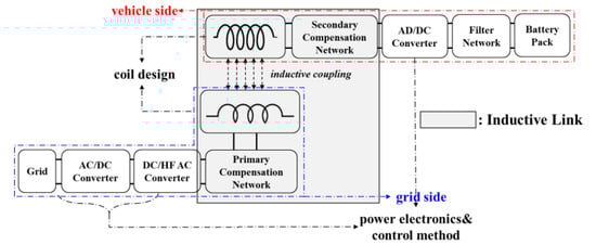
Figure 1.
Block diagram of general inductive power transfer (IPT) system.

Table 1.
Features of compensation networks.
The equivalent circuit model of the IPT system applying SS compensation topology is shown in Figure 2. In this IPT system, load resistance can be calculated as follows:
where Qs = w0LS/RS. When the inductances of TX coil and RX coil are LP and LS, respectively, the compensation capacitance at the primary side and secondary side can be expressed as follows:
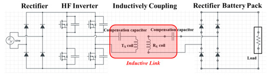
Figure 2.
The IPT system model using series-series (SS) compensation topology.
Also, the total impedance ZT of the inductive link is calculated by Equation (3).
where RP, RS, and M are the TX coil resistance, RX coil resistance, and mutual inductance between the two coils, respectively. In addition, the quality factors of the TX coil QP and RX coil QS can be expressed as follows:
For IPT systems, the coupling coefficient k is very small because the two coils are coupled very loosely. For the series-series (SS) topology, the TX coil and RX coil are connected to the compensation capacitors in series. When the capacitors are added to the primary side and secondary side, the system resonates, and the power transferred to the load increases. If the currents through the TX coil and the RX coil are IP and IS, respectively, the output power is written as follows:
In addition, the input power can be expressed as follows:
The transfer power efficiency can be calculated by Equation (7).
The maximum efficiency is achieved at RP/RS = (1+k2QPQS)1/2, and it can be expressed as follows:
According to Equation (7), the transfer power efficiency depends on the coupling coefficient between the TX coil and the RX coil, and the larger the coupling coefficient, the higher the efficiency.
2.2. Flux Pipe for IPT System
Magnetic couplers can be classified into planar type and solenoid type. The planar type has a magnetic field structure to perpendicularly pass from its center, and it is very sensitive to misalignment [24,25]. In particular, the coupling coefficient of the planar type becomes nearly zero when the lateral misalignment is approximately 40% of the coil size. The solenoid type has a magnetic field structure parallel to the coils, so it is less sensitive to misalignment [26,27,28,29]. For the solenoid type, if the secondary coil is moved laterally from the center of the primary coil, the total flux penetrating the secondary winding will decrease only slightly, and the reduction in the coupling coefficient will be small. Therefore, the solenoid type has excellent tolerance to lateral misalignment. Figure 3 shows magnetic field structures according to different winding types.
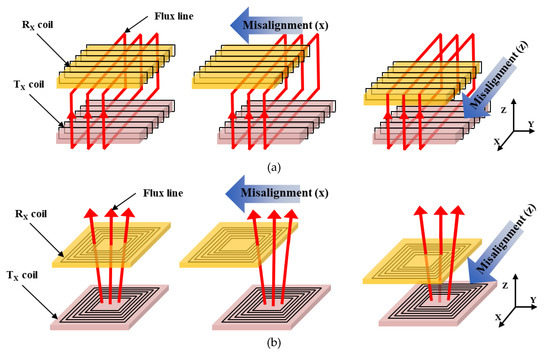
Figure 3.
Magnetic field by magnetic coupler type: (a) planar type and (b) solenoid type.
Figure 4 shows configurations and dimensional parameters of the RX coils for flux pipe-based inductive link. The ideal solenoid coil for the flux pipe can be used to simplify modeling, but it is not an accurate model because it requires a turn-to-turn pitch when the solenoid coil is actually manufactured. The helix model, on the other hand, is relatively accurate compared to the ideal solenoid because it takes into account the turn-to-turn pitch that can occur during production. In this paper, we set the helix angle of the coil to 45° and all other specifications such as the winding turns and coil sizes. The double helix coil is in two layers, of which the tilted angle θ is 45° to form cross configuration. The inner layer and outer layer are connected in series.
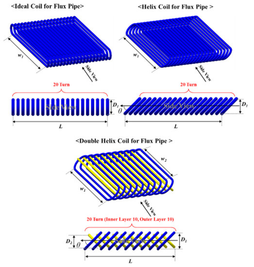
Figure 4.
The structures of the RX coils for flux pipe-based inductive link.
Table 2 shows the specifications of the simulation models for comparing the performance of the inductive link according to the type of the flux pipe. Aside from the flux pipe models described above, a planar coil in the form of double D (DD), which are applied to conventional IPT systems, was also modeled together for comparative study. In the case of the flux pipe model, the coil size and winding turns were set to be the same, and the same model was used for the TX pad. In addition, the DD coil was designed to have the same number of turns within the same width and length, and Litz wire with 200 strands at 2.2 mm diameter was used for both the TX coil and the RX coil. The litz wire is used by most engineers and researchers for the two coils of wireless power transfer systems. [30,31,32]. Compensation capacitors connected in series with the coils on the secondary and primary sides were calculated using Equation (2).
Table 2.
Simulation models for comparative study of inductive link.
3. Characteristics Analysis
3.1. Coupling Coefficient Between Two Coils
One of the most important factors in the performance of an IPT system is the coupling coefficient between two coils. In this study, coupling coefficients according to the types of inductive links were calculated for electromagnetic analysis. Figure 5 shows the simulation results of magnetic field distribution in each model. This analysis was performed in the physical center without the misalignment of the RX coil, and the change in the coupling coefficient according to misalignment in the x, y, and z axis directions was simulated. Figure 6 shows the variation of the coupling coefficient with the size of misalignment in each direction. Here, misalignment in the z direction indicates misalignment in the gap direction between the RX coil and the TX pad, and x and y directions indicate lateral misalignment in the axial direction and the width direction of the coil, respectively.
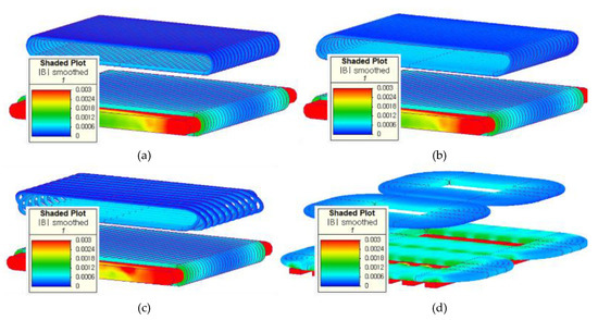
Figure 5.
The simulation results of magnetic distributions according to inductive link type. (a) Ideal flux pipe, (b) helix flux pipe, (c) double helix flux pipe, and (d) planar coil.
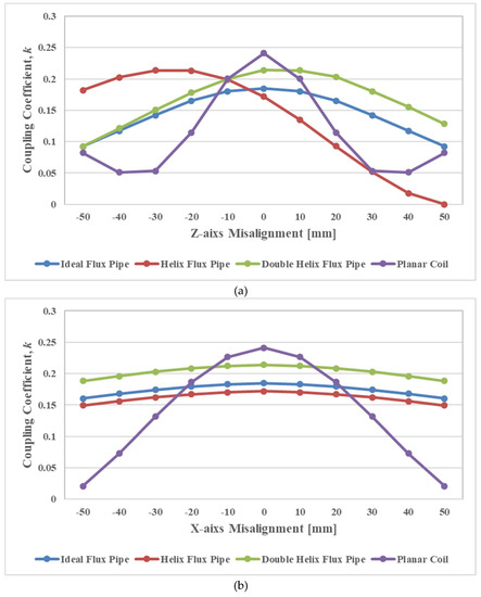
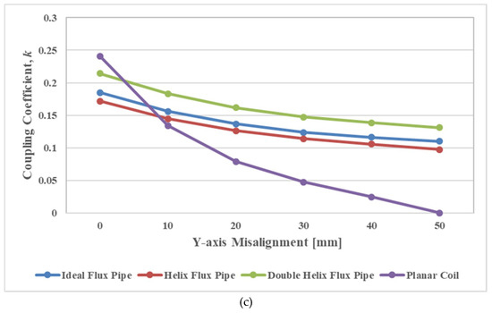
Figure 6.
The coupling coefficient according to the misalignment: (a) x direction misalignment, (b) y direction misalignment, (c) z direction misalignment.
As can be seen from the simulation results, the coupling coefficient between two coils in the aligned state is the largest in the conventional DD type. However, in the conventional DD type, as the misalignment increases, the coupling coefficient decreases rapidly. In particular, when the misalignment in the y direction reaches 50 mm, the coupling coefficient becomes almost zero. In the conventional DD type, the coupling coefficient increases when the z misalignment is greater than 40 mm because one of the two symmetrical D coils enters the alignment region again as the size of the misalignment increases.
Helix flux pipe type has high coupling coefficient tolerance for misalignment in y and z directions but low tolerance in the x direction. In particular, the coupling coefficient in the x direction was asymmetrical with respect to the physical origin. This is because the helix coil has an asymmetrical shape with respect to the coil center due to the tiled angle. Therefore, the existing actual flux pipe type has such asymmetrical characteristics around the physical center.
On the other hand, the double helix flux type has a relatively high coupling coefficient and excellent tolerance of the coupling coefficient reduction according to misalignment. Coupling coefficients due to misalignment in the x-direction are asymmetrical, but are much smaller than in helix coils. The asymmetry characteristic of the double helix type is due to the difference in the outer diameter of the inner and outer layers. However, this result shows that the double helix topology can be considered as a solution to the problem of asymmetry according to the misalignment of the actual flux pipe.
3.2. Power Transfer Efficiency of IPT System
Figure 7 shows the calculation results of maximum power transfer efficiency in each model. The reduction rate of the maximum power transfer efficiency due to a misalignment on the y-axis was relatively large for the conventional DD type; specifically, misalignment of 40 mm or more was found to lead to the high reduction effect. Also, this is the lowest maximum power transfer efficiency due to low self-inductance of the TX pad. On the other hand, the most suitable inductive link for the IPT system was the double helix flux pipe type in terms of the maximum power transfer efficiency and their reduction rate.
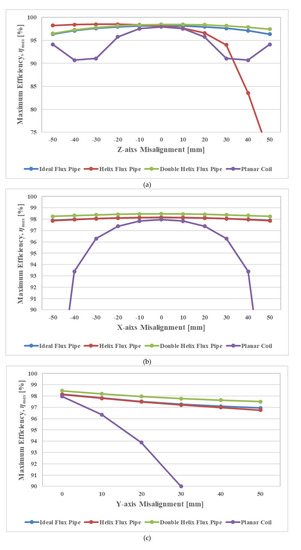
Figure 7.
The maximum power transfer efficiency according to the misalignment: (a) x direction misalignment, (b) y direction misalignment, (c) z direction misalignment.
To determine the impact of the load resistance on the power transfer efficiency, the coil-to-coil power transfer efficiency at a resonance frequency of 85 kHz for each inductive link model was evaluated. These simulation results are presented in Figure 8. From the simulation results, it is confirmed that the optimal load resistances for the ideal flux pipe type, helix flux type, and planar coil type are 15 Ω in all cases. On the other hand, the optimal load resistance for the double helix flux pipe type is 20 Ω. The double helix flux pipe type has a relatively constant power transfer efficiency value according to the load resistance.
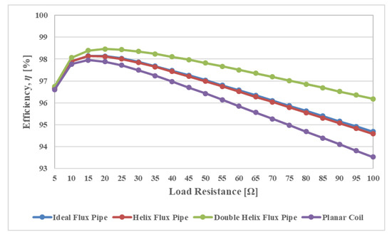
Figure 8.
Effect of load resistance on the power transfer efficiency.
4. Discussion
This paper deals with a double helix (DH) flux pipe-based inductive link for wireless charging of electric vehicles (EVs). In a wireless charging system for EVs, a misalignment tolerance is very important for high-efficiency performance. Planar coils such as circular coils, rectangular coils, and double D (DD) coils have a relatively high power transfer efficiency when the two coils are aligned, but they have a low misalignment tolerance performance for two-coil coupling and power transfer efficiency. Due to the poor misalignment tolerance performance of wireless charging system applying the planar coils, various studies have been conducted on the flux pipe topology with an excellent misalignment tolerance. In this paper, we propose a novel inductive link based on a flux pipe and series-series (SS) compensation network. The proposed flux pipe uses a double helix coil, which improves the coupling coefficient and misalignment tolerance. In the proposed flux pipe topology, two helical coils are tilted at opposite angles of 45° to form a cross configuration. To verify the feasibility of the proposed DH model, the coupling coefficient between two-coils and the power transfer efficiency of the inductive link according to misalignment were analyzed. In addition to the DH coil model, the characteristics of the inductive link models with ideal solenoid coil, helix coil and DD coil were also analyzed. The results show that the proposed model has the best characteristics in terms of the power transfer efficiency and tolerance against misalignments. All of these models have the same coil size and number of turns, so it is expected that the cost of manufacturing a two-coil system is almost the same. Although not covered in this study, the coils of the flux pipe topology including the DH coil can be manufactured by using a traverse winding machine used in existing power transformers, so it is easy to manufacture. In addition, it is expected that it can be manufactured relatively robustly because it can maintain winding tension. The analytical results demonstrate that the proposed DH flux pipe-based inductive link is capable of effective misalignment tolerance performance. However, further research on the applicability of the proposed model is needed, with the fabrication and testing of prototype models.
5. Conclusion
An inductive link including a double helix flux pipe was proposed and analyzed for an IPT system of an EV. The simulation results confirm that the proposed double helix type has the best characteristics in terms of the power transfer efficiency and tolerance against misalignments. At the same time, the double helix flux pipe type also showed an excellent coupling coefficient. This means that the novel flux pipe type proposed in this paper has potential as an inductive link for IPT systems of electric vehicles. However, further research on the applicability of the proposed double helix flux pipe is needed through the fabrication and test of prototype models. This study is expected to serve as a reference for performance improvements of IPT systems for electric vehicles.
Author Contributions
The authors contributed to this work by collaboration. Y.J.H. designed the overall structure of the paper and performed the simulations; J.M.K. performed the data analysis. All authors have read and agreed to the published version of the manuscript.
Acknowledgments
This work was supported by the Korea Institute for Advancement of Technology under Grant P0006943.
Conflicts of Interest
The authors declare no conflict of interest.
References
- Matias, R.; Cunha, B.; Martins, R. Modeling inductive coupling for wireless power transfer to integrated circuits. In Proceedings of the IEEE Wireless Power Transfer (WPT), Perugia, Italy, 15–16 May 2013; Volume 2, pp. 198–201. [Google Scholar]
- Kalwar, K.A.; Aamir, M.; Mekhilef, S. Inductively coupled power transfer (ICPT) for electric vehicle charging—A review. Renew. Sustain. Energy Rev. 2015, 47, 462–475. [Google Scholar] [CrossRef]
- Lempidis, G.; Zhang, Y.; Jung, M.; Marklein, R.; Sotiriou, S.; Ma, Y. Wired and wireless charging of electric vehicles. In Proceedings of the 2014 4th International Electric Drives Production Conference (EDPC), Nuremberg, Germany, 30 September–1 October 2014; pp. 1–7. [Google Scholar]
- Wang, R.; Zhou, X.; Zheng, J.; Yang, D. Research on the efficiency of wireless power transfer system based on multi-auxiliary transmitting coils. In Proceedings of the 4th International Conference on Information Science and Control Engineering (ICISCE), Changsha, China, 21–23 July 2017; pp. 1677–1681. [Google Scholar]
- Zhai, L.; Zhong, G.; Cao, Y.; Hu, G.; Li, X. Research on Magnetic Field Distribution and Characteristics of a 3.7 kW Wireless Charging System for Electric Vehicles under Offset. Energies 2019, 12, 392. [Google Scholar] [CrossRef]
- Ahmad, A.; Alam, M.S.; Chabaan, R. A Comprehensive Review of Wireless Charging Technologies for Electric Vehicles. IEEE Trans. Transp. Electrif. 2018, 4, 38–63. [Google Scholar] [CrossRef]
- Moon, H.; Kim, S.; Park, H.H.; Ahn, S. Design of a resonant reactive shield with double coils and a phase shifter for wireless charging of electric vehicles. IEEE Trans. Magn. 2015, 51, 8700104. [Google Scholar]
- Yang, Y.; Mohamaed, E.B.; Yuanfeng, L.; Yassine, B.; Joeri, V.M.; Omar, H. Design Methodology, Modeling, and Comparative Study of Wireless Power Transfer Systems for Electric Vehicles. Energies 2018, 11, 1716. [Google Scholar] [CrossRef]
- Cai, C.; Wang, J.; Fang, Z.; Zhang, P.; Hu, M.; Zhang, J.; Li, L.; Lin, Z. Design and Optimization of Load-Independent Magnetic Resonant Wireless Charging System for Electric Vehicles. IEEE Access 2018, 6, 17264–17274. [Google Scholar] [CrossRef]
- Li, Z.; Yu, C.; Liwen, L.; Tao, Z.; Steve, K. Mitigation Conducted Emission Strategy Based on Transfer Function from a DC-Fed Wireless Charging System for Electric Vehicles. Energies 2018, 11, 477. [Google Scholar]
- Li, S.; Mi, C. Wireless Power Transfer for Electric Vehicle Applications. IEEE J. Emerg. Sel. Top. Power Electron. 2015, 3, 4–17. [Google Scholar]
- Elnail, K.E.I.; Huang, X.; Xiao, C.; Tan, L.; Haozhe, X. Core Structure and Electromagnetic Field Evaluation in WPT Systems for Charging Electric Vehicles. Energies 2018, 11, 1734. [Google Scholar] [CrossRef]
- Imura, T.; Okabe, H.; Hori, Y. Basic experimental study on helical antennas of wireless power transfer for Electric Vehicles by using magnetic resonant couplings. In Proceedings of the 2009 IEEE Vehicle Power and Propulsion Conference (VPPC ’09), Dearborn, MI, USA, 7–10 September 2009. [Google Scholar]
- Sabki, S.A.; Tan, N.M.L. Wireless power transfer for electric vehicle. In Proceedings of the 2014 IEEE 8th International Power Engineering and Optimization Conference (PEOCO2014), Langkawi, Malaysia, 24–25 March 2014; pp. 41–46. [Google Scholar]
- Zhao, J.; Cai, T.; Duan, S.; Feng, H.; Chen, C.; Zhang, X. A general design method of primary compensation network for dynamic WPT system maintaining stable transmission power. IEEE Trans. Power Electron. 2016, 31, 8343–8358. [Google Scholar] [CrossRef]
- Kalwar, K.; Mekhilef, S.; Seyedmahmoudian, M.; Horan, B. Coil design for high misalignment tolerant inductive power transfer system for EV charging. Energies 2016, 9, 937. [Google Scholar] [CrossRef]
- Budhia, M.; Covic, G.A.; Boys, J.T. Design and Optimisation of Magnetic Structures for Lumped Inductive Power Transfer Systems. IEEE ECCE 2009, 2009, 2081–2088. [Google Scholar]
- Khaligh, A.; Dusmez, S. Comprehensive topological analysis of conductive and inductive charging solutions for plug-in electric vehicles. IEEE Trans. Veh. Technol. 2012, 61, 3475–3484. [Google Scholar] [CrossRef]
- Zhang, W.; Wong, S.-C.; Tse, C.K.; Chen, Q. Analysis and comparison of secondary series- and parallel-compensated inductive power transfer systems operating for optimal efficiency and load-independent voltage-transfer ratio. IEEE Trans. Power Electron. 2014, 29, 2979–2990. [Google Scholar] [CrossRef]
- Duan, C.; Jiang, C.; Taylor, A.; Bai, K. Design of a zero-voltage switching large-air-gap wireless charger with low electric stress for electric vehicles. IET Power Electron. 2013, 6, 1742–1750. [Google Scholar] [CrossRef]
- Boys, J.T.; Covic, G.; Green, A.W. Stability and control of inductively coupled power transfer systems. Proc. IEE Electr. Power Appl. 2000, 147, 37–43. [Google Scholar] [CrossRef]
- Chinthavali, M.; Zhiqiang, W.; Campbell, S. Analytical modeling of wireless power transfer (WPT) systems for electric vehicle application. In Proceedings of the 2016 IEEE Transportation Electrification Conference & Expo (ITEC 16), Dearborn, MI, USA, 27 June 2016; pp. 1–8. [Google Scholar]
- Spanik, P.; Frivaldsky, M.; Drgona, P.; Jaros, V. Analysis of proper configuration of wireless power transfer system for electric vehicle charging. ELELKTRO 2016, 2016, 231–237. [Google Scholar]
- Ishizaki, T.; Fukada, D.; Awai, I. A novel concept for 2-dimensional free-access wireless power transfer system using asymmetric coupling resonators with different sizes. In Proceedings of the IEEE MTT-S International Microwave Workshop Series on Innovative Wireless Power Transmission: Technologies, Systems, and Applications, Kyoto, Japan, 12–13 May 2011; pp. 243–246. [Google Scholar]
- Budhia, M.; Covic, G.A.; Boys, J.T.; Huang, C.Y. Development and evaluation of single sided flux couplers for contactless electric vehicle charging. In Proceedings of the IEEE Energy Conversion Congress and Exposition, Phoenix, AZ, USA, 17–22 September 2011; pp. 614–621. [Google Scholar]
- Babatunde, O.; Julius, P.; Richard, B. Finite Element Modeling and Analysis of High Power Low-loss Flux-Pipe Resonant Coils for Static Bidirectional Wireless Power Transfer. Energies 2019, 12, 3534. [Google Scholar]
- Nguyen, T.D.; Li, S.; Li, W.; Mi, C.C. Feasibility study on bipolar pads for efficient wireless power chargers. In Proceedings of the IEEE Applied Power Electronics Conference and Exposition-APEC, Fort Worth, TX, USA, 16–20 March 2014; pp. 1676–1682. [Google Scholar]
- Chigira, M.; Nagatsuka, Y.; Kaneko, Y.; Abe, S.; Yasuda, T.; Suzuki, A. Small-size light-weight transformer with new core structure for contactless electric vehicle power transfer system. In Proceedings of the IEEE Energy Conversion Congress and Exposition, Phoenix, AZ, USA, 17–22 September 2011; pp. 260–266. [Google Scholar]
- Takanashi, H.; Sato, Y.; Kaneko, Y.; Abe, S.; Yasuda, T. A large air gap 3 kW wireless power transfer system for electric vehicles. In Proceedings of the IEEE Energy Conversion Congress and Exposition (ECCE), Raleigh, NC, USA, 15–20 September 2012; pp. 269–274. [Google Scholar]
- Munir, A.B.; Kumar, N.; Karim, M.E.; Reza, A.W.; Barman, S.D. Wireless powering by magnetic resonant coupling: Recent trends in wireless power transfer system and its applications. Renew. Sustain. Energy Rev. 2015, 51, 1525–1552. [Google Scholar]
- Mizuno, T.; Yachi, S.; Kamiya, A.; Yamamoto, D. Improvement in efficiency of wireless power transfer of magnetic resonant coupling using magnetoplated wire. IEEE Trans. Magn. 2011, 47, 4445–4448. [Google Scholar] [CrossRef]
- Wojda, R.P. Winding resistance and power loss for inductors with litz and solid-round wires. IEEE Trans. Ind. Appl. 2018, 54, 3548–3557. [Google Scholar] [CrossRef]


© 2020 by the authors. Licensee MDPI, Basel, Switzerland. This article is an open access article distributed under the terms and conditions of the Creative Commons Attribution (CC BY) license (http://creativecommons.org/licenses/by/4.0/).