Article

Material Characterization and Analysis on the Effect of Vibration and Nail Penetration on Lithium Ion Battery

by
Ajeet Babu K. Parasumanna
*,
Ujjwala S. Karle
and
Mangesh R. Saraf
The Automotive Research Association of India, Pune 411038, India
*
Author to whom correspondence should be addressed.
World Electr. Veh. J. 2019, 10(4), 69; https://doi.org/10.3390/wevj10040069
Submission received: 9 August 2019 / Revised: 16 October 2019 / Accepted: 25 October 2019 / Published: 30 October 2019

Abstract

:
Battery packaging in a vehicle depends on the cell chemistry being used and its behavior plays an important role in the safety of the entire battery pack. Chemical degradation of various parts of a cell such as the cathode or anode is a concern as it adversely affects performance and safety. A cell in its battery pack once assembled can have two different mechanical abuse condition. One is the vibration generated from the vehicle and the second is the intrusion of external elements in case of accident. In this paper, a commercially available 32,700 lithium ion cell with lithium iron phosphate (LFP) chemistry is studied for its response to both the abuse conditions at two different states of charge (SoC). The primary aim of this study is to understand their effect on the surface morphology of the cathode and the anode. The cells are also characterized to study impedance behavior before and after being abused mechanically. The cells tested for vibration were also analyzed for dynamic stiffness. A microscopy technique such as scanning electron microscopy (SEM) was used to study the surface morphology and electrochemical impedance spectroscopy (EIS) characterization was carried out to study the internal resistance of the cell. It was observed that there was a drop in internal resistance and increase in the stiffness after the cells subjected to mechanical abuse. The study also revealed different morphology at the center and at the corner of the cell subjected to nail penetration at 50% SoC.

1. Introduction

The lithium ion battery (LiB) nowadays is used for various applications because of its high specific capacity, lower weight, and longer cycle life. Today lithium ion batteries (LiBs) gravimetric energy density is up to 260 Wh kg−1 which was not expected 10 years ago. The specific energy of a Li-ion battery can be further enhanced by Ni-rich electrodes. Today, the LiB has been transformed from a device powering portable electronics to an energy solution for different sectors and automotive is one of the biggest beneficiary of this technology. This transformation has led to research for improving the energy density of LiBs [1,2,3,4,5,6]. A LiB contains an electrolyte, separator, cathode and anode in different form factors such as cylindrical, prismatic and pouch. The cylindrical form factor varies from standard 18,650 to new designs such as 21,700, 32,700 etc. The anode stores the Li+ ions during charging and the cathode acts as reservoir of Li+ ions during discharging. The solid electrolyte interphase (SEI) layer is formed during the charge–discharge cycle and it should properly adhere to the electrode material as it prevents the electrolyte decomposition thereby increasing cycling stability to prevent the electrolyte decomposition increasing cycling stability. As the negative electrode is dominated by carbonaceous materials, many improvements in the cell are targeted at the positive terminal. It has been emphasized that cathode material is identified as the most promising component for improvement of the lithium ion battery. There have been various types of cathode materials developed in recent times to satisfy different functional requirements and also to store more energy. Olivine LiFePO4 was first developed by Goodenough and his co-workers in 1997. Lithium iron phosphate (LFP) is the most promising cathode material for large-scale lithium ion batteries because of its safety and low cost [7,8,9,10,11,12]. Safety of cells is one of the primary requirement while being considered for any vehicular applications because the battery pack of any xEV consists of hundreds of cells connected in series or parallel to produce high voltage and current The topotactic reaction was first demonstrated in the 1970s, and layered Li transition metal oxides (LiMO2, M = Co, Ni, Mn) have been a shining star throughout the research and innovation in intercalation materials due to their appealing merits. The LiMO2 cells are also used for power tools transiting from power tools to electric vehicles, but an environmentally hazardous Ni/Cd battery presently meets the requirements. The boost in the specific energy of LiB cells can also be achieved by increasing the cell voltage and/or the specific capacities of the electrodes. The cell is subjected to vibration once mounted in the vehicle and the structural stability of the cell needs to be evaluated for this condition. Generally, the cells with a single kind of transition metal ion suffers from safety concerns and structural instability. Various researchers have compared and stated that the vibration imparted in batteries is comparable with corresponding position of conventional cars [13,14,15,16,17]. United states advanced battery consortium (USABC) recommends both random vibration and sine harmonic vibration [18]. European regulation ECE R100.2 involves swept sine vibration only in the Z direction [19]. With respect to standards adopting sine vibrations, the acceleration suggested by USABC is much higher than the ECE standard. Apart from the existing vibration which happens during the lifetime of the cell fitted in the vehicle, the cell may also experience extreme abuse such as in the event of an accident it is likely that an external object can penetrate the battery pack. Penetration of cells by any sharp object can be one of the reasons for damage during such conditions. It is thus important to understand the behavior of the cell in these extreme abuse conditions as well. The nail penetration test is recommended as per Automotive Industry Standard 048 [20]. A nail-penetrated cell, along with a new cell, is generally used for further comparison by a material characterization study.
Material characterization techniques by scanning electron microscopy (SEM) are used to study morphology, and energy-dispersive X-ray (EDX) analysis is used to study elemental composition. The changes taking place in the electrode of an abused cell are observed and can be compared with the electrodes of the new cell. In research work carried out by Wanga et al. the SEM technique was used to study the cathode and anode of the 18,650 Li-ion cell. Schindler U. et al. used advanced SEM technology to study the degradation phenomenon in LiB. They used detector strategies and voltage contrast to improve the resolution of images of cell electrodes [21]. Liu et al. used electrochemical impedance spectroscopy (EIS) and SEM to check and relate the resistance stability of electrode and the morphology characteristics [22]. Babu P A et al. studied the performance of the cell by SEM analysis of the cathode and anode for different abuse conditions [23]. The above researchers used the SEM technique extensively for their study.
EIS is another characterization technique that has revealed its importance and value through several applications [24]. It has been shown that it is a powerful device to characterize electrochemical processes occurring in a cell and to thereby estimate useful states indicators [25]. Therefore, it has become a major tool for investigating the properties of cells in electric vehicles (EVs) and hybrid electric vehicles (HEVs) [26,27]. Farhat et al. used EIS to study the charge transfer resistance and diffusion resistance of cell. Their research states that in EIS result, the charge transfer resistance is obtained at higher frequency range than the frequency of range of diffusion resistance [28]. Liu et al. in their work investigated the effect of microstructure morphology on the impedance response. They found out that the EIS curve varies with the nature of reaction kinetics in the solid-electrolyte interface, exchange current density and dielectric property of the materials [22]. Illig et al. in this study, investigates the impedance response of an 18,650 cell inside a frequency range of 100 kHz–2 μHz by merging electrochemical impedance spectroscopy and time-domain measurements. This study identified the dominating physical processes which were hidden in the impedance spectrum of the cell [29]. Although its robustness and high accuracy results, it is still more common in laboratory tests than in online field equipment.
Apart from material and electrochemical behavioural study, in recent times, various researchers have started to use mechanical behavior as an indicator of cell status [30,31,32]. Hooper et al. claimed that the natural frequency of a li-ion cell is independent of its state of charge (SoC), but frequency information of the same cells with various SoCs was not investigated in his work [33]. Pham et al. asserted a linear relationship between the SoC and frequency of a cell based on the fact that the frequency response function (FRF) curves with different SoCs had similar spacing [34].
Various researchers have worked on characterizing the new cathode materials, but very little literature is available with respect to behavior of cell components when it comes to external abuse conditions. In this research a commercially available LFP-chemistry based 32,700 cylindrical form factor LiB is selected for the study. The cell was subjected to two different abuse conditions i.e., Nail penetration and sinusoidal vibration. Nail penetration was done at two different SoC i.e., 100% and 50% and vibration was carried out at 100% SoC. In the case of nail penetration, the cells electrode morphology was studied using SEM along with EDS and in the case of vibration the cells were characterized for its internal resistance and dynamic stiffness. All the properties are compared with the benchmark condition of a new cell.

2. Experimental Setup

The batteries were charged under constant current and constant voltage protocol (CC-CV). A bitrod cell cycler was used for carrying out charging and discharging. The nail penetration test was carried out at two different SoC i.e., 100% and 50%. The cell was penetrated with a mild steel (conductive) pointed rod of 3 mm diameter, which was electrically insulated from the test fixture. The rate of penetration was kept at 8 cm/s. The orientation of the penetration was perpendicular to the electrode plates. The cell was observed, with the rod remaining in place, for one hour after the test. The test was carried out using a hydraulic actuator.
Sinusoidal vibration test at single axis wherein the cell was vertically held was carried out in a single-axis shaker table. An aluminium fixture was designed in such a way that all degrees of freedom were arrested and the vibration effect was directly imparted to the internal structure of the cell. The top and bottom of the cell was covered with non-metal to prevent formation of any electrical connection. Refer to Figure 1 for the experimental setup. Accelerometers were placed on the cells to measure the vibration profile and to control the tests. The test fixtures were properly secured to the shaker table and the frequency and “g” Value for the sinusoidal vibration in vertical direction is given in Table 1. Six numbers of cells were tested for both the abuse testing for statistical confidence.
To carry out morphological analysis the samples were disassembled and the electrodes which were spirally wound together with the separator in between them were carefully taken out. The SEM was performed on sample electrodes of new and nail-penetrated cells. The surface morphology study was done at different magnification and the voltage was kept as 20 kv. The compositional analysis was conducted using an Oxford detector EDX analyzer. EIS was performed to check the internal resistance of the cell at a different SoC. EIS was done when the cell was fully charged in the new cell and when it had completed vibration testing. The frequency range for EIS is kept high, and the minimum frequency is 10−2 Hz and the maximum frequency is 5 × 10⁵ Hz. The experimental setup which is used for calculation of dynamic stiffness is shown in Figure 2. This setup consisted of four batteries fixed in the vibration testing fixture, impact hammer, an accelerometer, analyzer learning management system (LMS). The fixture was rigidly fixed and the cell was mounted in vertical direction as in the real operating conditions. The hammer was used to excite the test specimen and the accelerometer was mounted on the top of the cell and used to record the input side acceleration. Calibration of sensors is done before each measurement. Five averages were taken where the averages type is linear average. The resulting signals captured from the force transducer and accelerometer were then analysed by using LMS software. Refer to Figure 2 for the experimental setup.

3. Results and Discussion

3.1. Morphology Analysis

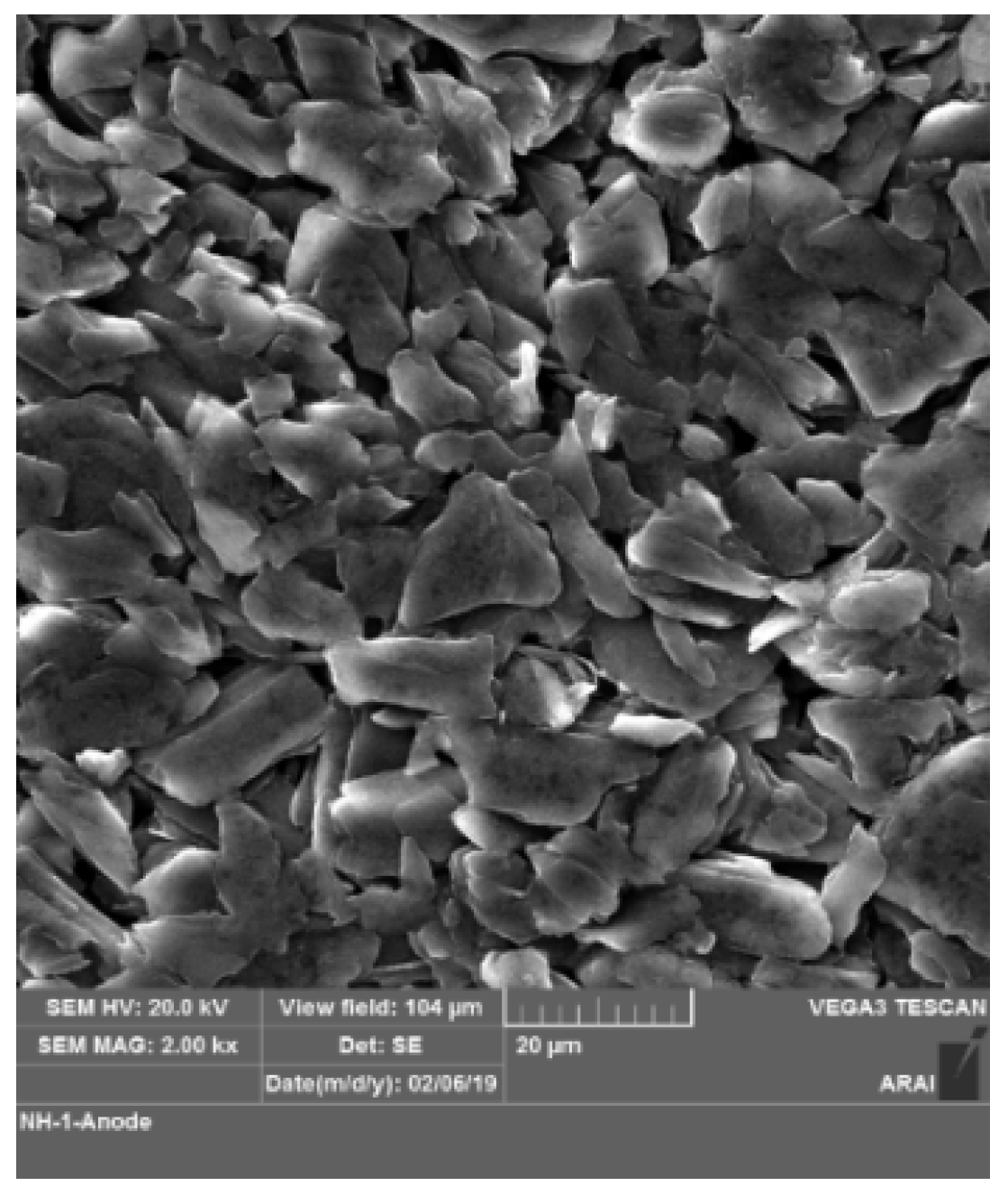
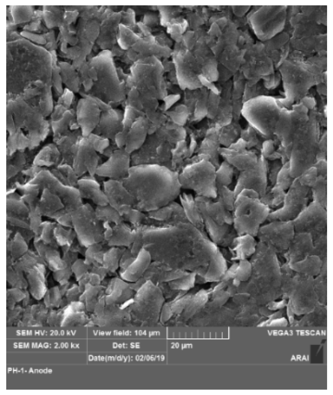
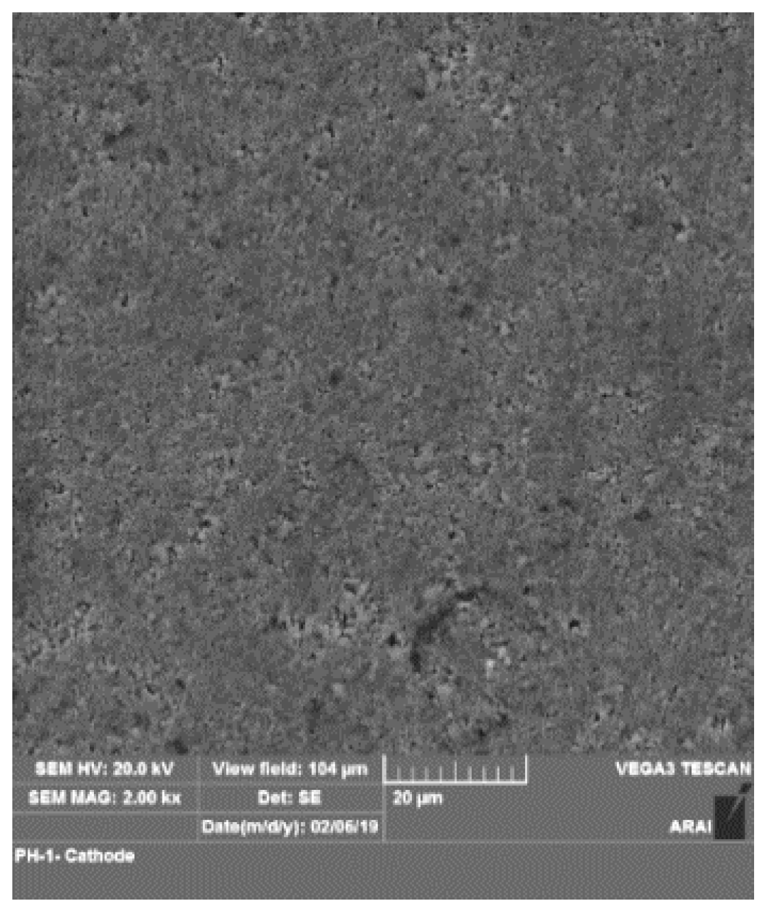
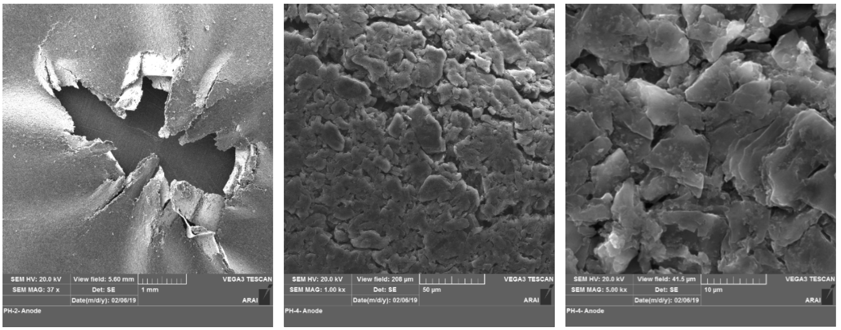
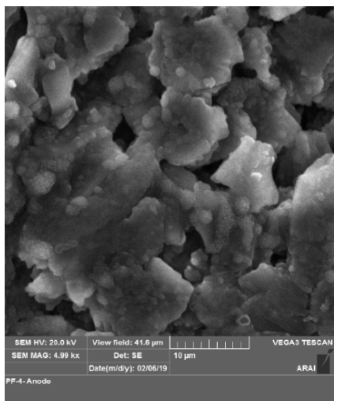
The surface morphology of the anode and cathode of the new cell is given in Figure 3 and Figure 4 respectively. In the case of samples which had undergone nail penetration at 50% SoC, the location for composition analysis was done at two distinct places. The first location was at the centre of the cell where in the cylindrical rod had pierced the cell and the second location was at top of the electrode which is away from the centre where there is no physical damage during the testing. In the case of samples which have undergone nail penetration at 50% SoC, no changes in anode morphology were observed at location away from centre as compared with new cells shown in Figure 5, thus it can be stated that the material could be further used for recovery of carbon material. In the cathode, cracks were observed in the morphology of the particles as shown in Figure 6 and no other impurity or foreign elements presence were detected. The active material may be used again for reuse applications. In the centre location, the anode showed layer separation distinctly along with multiple cracks as shown in Figure 7. In the cathode, the particles were completely destroyed and cracks were observed as shown in Figure 8.
In the case of samples that had undergone nail penetration at 100% SoC, the test conditions led to the explosion of the cells and thus the electrode sample could not be distinguished as centre and away from centre. The anode surface showed inhomogeneity in the particle structure and particle size was not uniform as shown in Figure 9. In the cathode, carbon particles were observed which is due to transfer from anode and also structure was destroyed along with the presence of solidification network due to melting as a result of firing as shown in Figure 10. In a new cell, the average particle size of the anode is 12 µm and 0.56 µm for the cathode. In the case of nail penetrated samples the particle size of the anode reduced to 7 µm and the particle size of cathode increased to 1 µm.
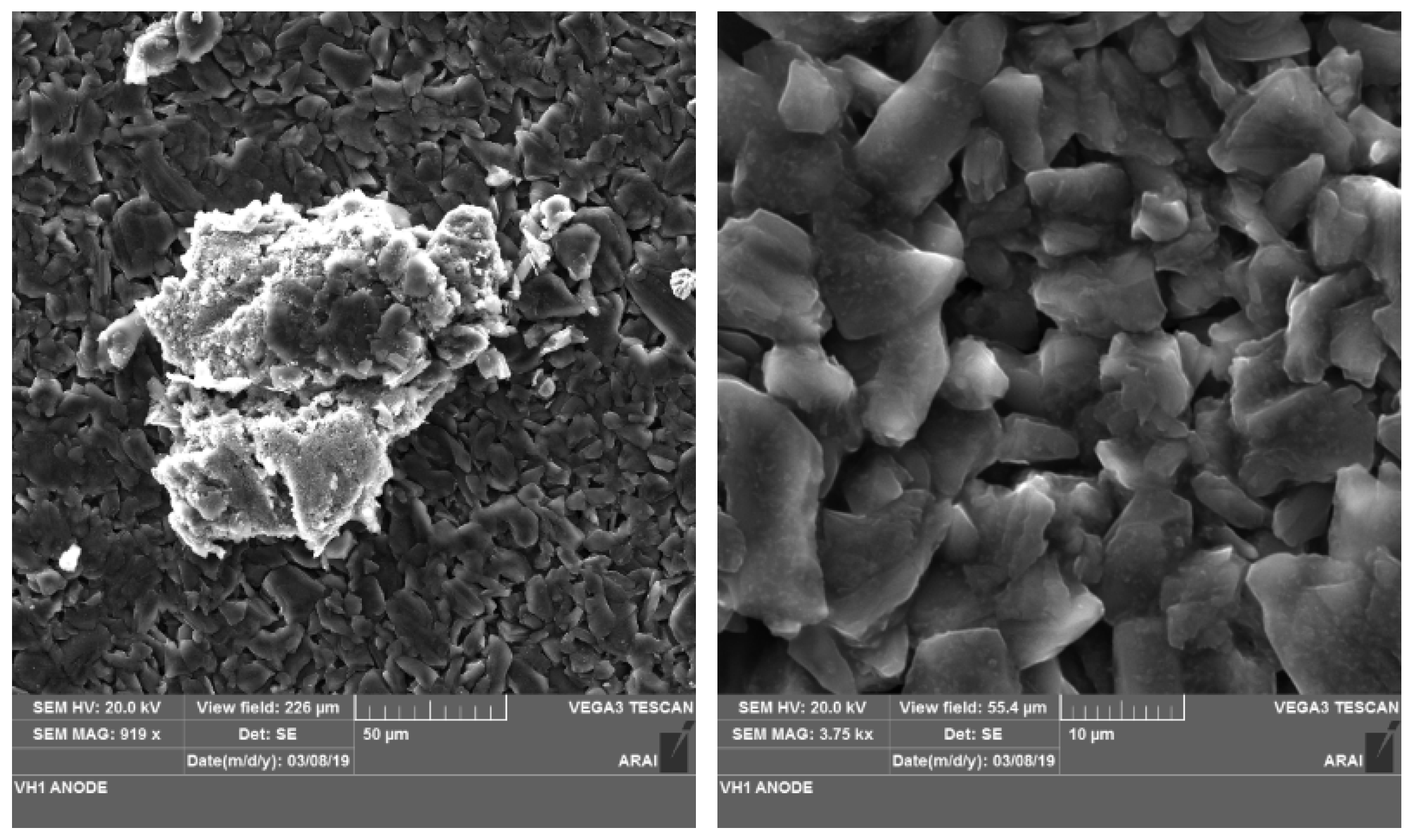
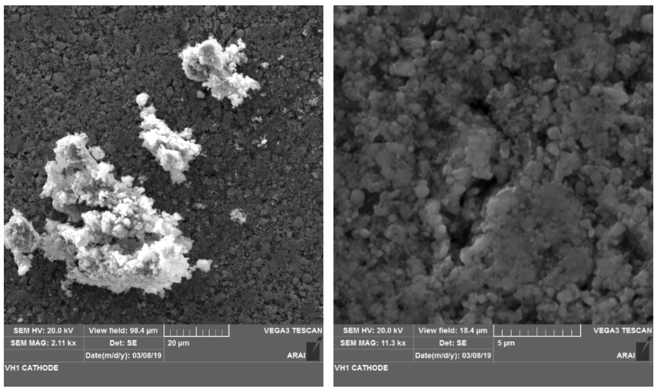
In the case of samples which have undergone sinusoidal vibration at 100% SoC, the anode was found intact and was comparable with the surface of the new cell anode; however, throughout the surface was the presence of a tower-like structure which had grown due to deposition of elements from the cathode as shown in Figure 11. This could have happened during the vibration testing of the cell. Similarly, in the cathode the structure was fine with small spherical particles and agglomerates. The important observation was the formation of crater-like structure on the active material as shown in Figure 12.

3.2. Composition Analysis

Electrodes of a nail-penetrated cell at 50% and 100% SoC and for the cell tested for vibration were measured for its elemental composition using the EDX facility of the scanning electron microscopy and further compared with the electrodes of the new cell. In total six samples were tested and EDX readings were taken twice at each location for all samples.
In the case of samples which had undergone nail penetration at 50% SoC, the location for composition analysis was done at two distinct places as mentioned in the morphology study. With respect to the cathode, in the second location the elemental Wt.% for C, O, P and Fe was similar for before and after testing and thus there was no effect of abuse on the distribution of the elements excluding the structure and composition. In the center, the amount of iron increased from 26% to 52%, phosphorus decreased from 16% to 8%, oxygen decreased from 40% to 20% and carbon decreased from 13% to 7.5%. It thus can be said that when there is localized mechanical damage to the cell without leading to complete destruction/explosion then that leads to uneven distribution of the elements within the cathode surface. With respect to the anode, the elements such as C, O and P is found similar before and after the nail penetration test on the cell at both the locations.
In the case of samples which have undergone nail penetration at 100% SoC, the cell was completely destroyed due to thermal runaway. With respect to cathode, the elemental distribution of the cathode was similar to new cell. With respect to anode, the carbon Wt.% dropped from 86% to 33% and oxygen Wt.% increased from 6% to 48% and this could be due to the oxidation of the electrode due to thermal runaway. Traces of iron element is observed in the destroyed anode.
In case of samples which have undergone sinusoidal vibration at 100% SoC, the cell was further disassembled and it was observed that the anode has additional deposition of oxygen, phosphorus and iron which had come from the cathode, as compared to the new cell anode.

3.3. Internal Resistance Analysis

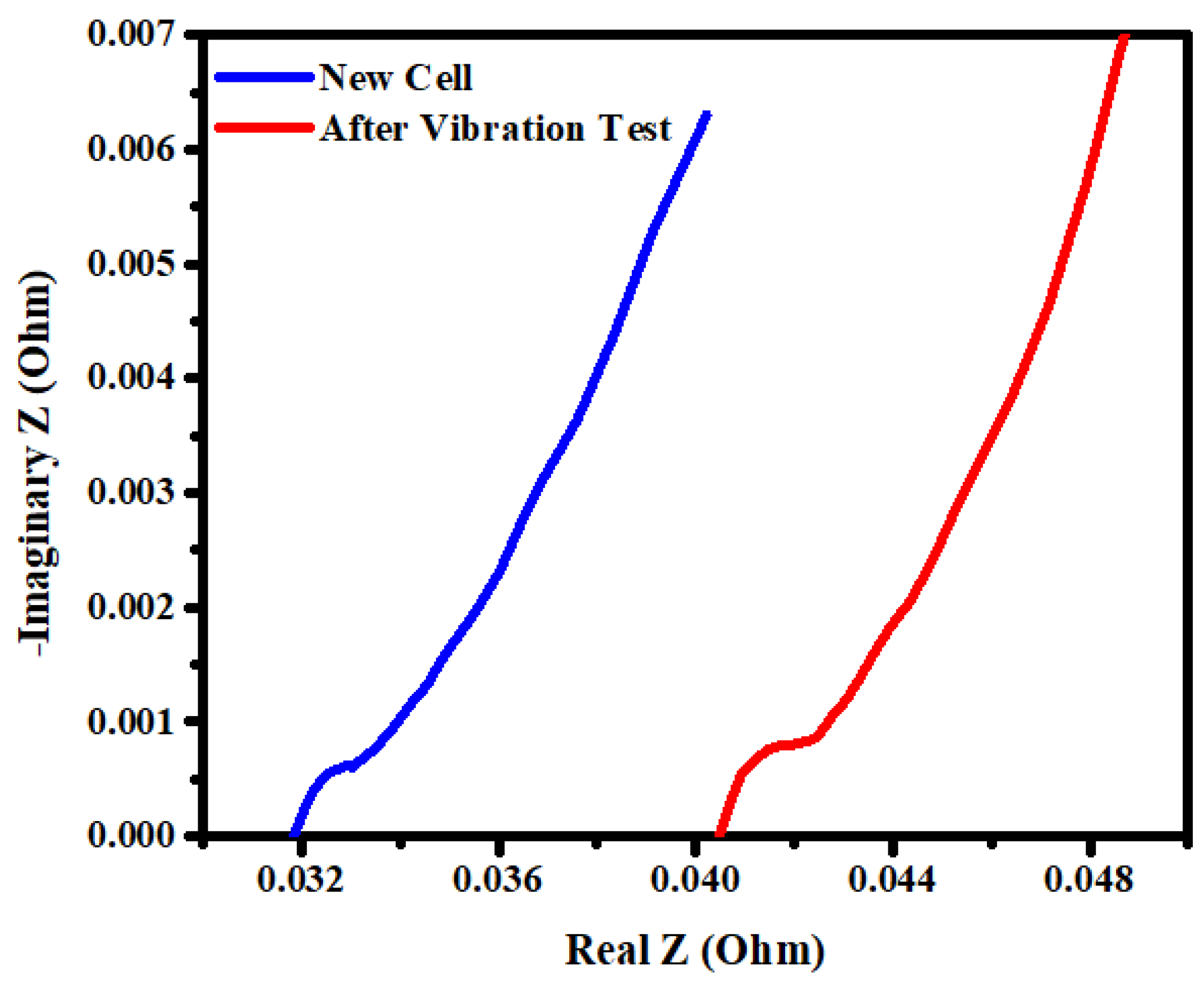
The cells were in 100% SoC capacity before the vibration test and the voltage was 3.3 V. After the test was over, the voltage of each cell dropped by 0.3–0.4 V and this corresponded to 50% SoC capacity. The EIS Nyquist plot gives the behavior of the cell. The internal resistance of the new cell at 50% SoC was found to be 30–35 mΩ and the EIS of the cell after the vibration test showed an increase in the internal resistance by 5%–25% as compared to the new cell. Six measurements were taken for each condition and the average value is reported. Refer to Figure 13 and Figure 14 for the typical EIS Nyquist plot for new and abused cells (vibration tested). It was thus observed that there was an increase in the internal resistance and performance of the cell that had been hampered after the cell had been subjected to vibration. One plausible explanation for of the fast increase of the resistance is that the surface film formed on the carbon electrode may not have been as firm or protective as it is expected to be, especially during vibration. When there is a vibration load, the internal temperature is expected to increase. The internal heat will not easily dissipate to the environment and the pressure will lead to gaseous release which will further lead to evaporation of electrolyte. This damages the surface film.

3.4. Dynamic Stiffness Analysis

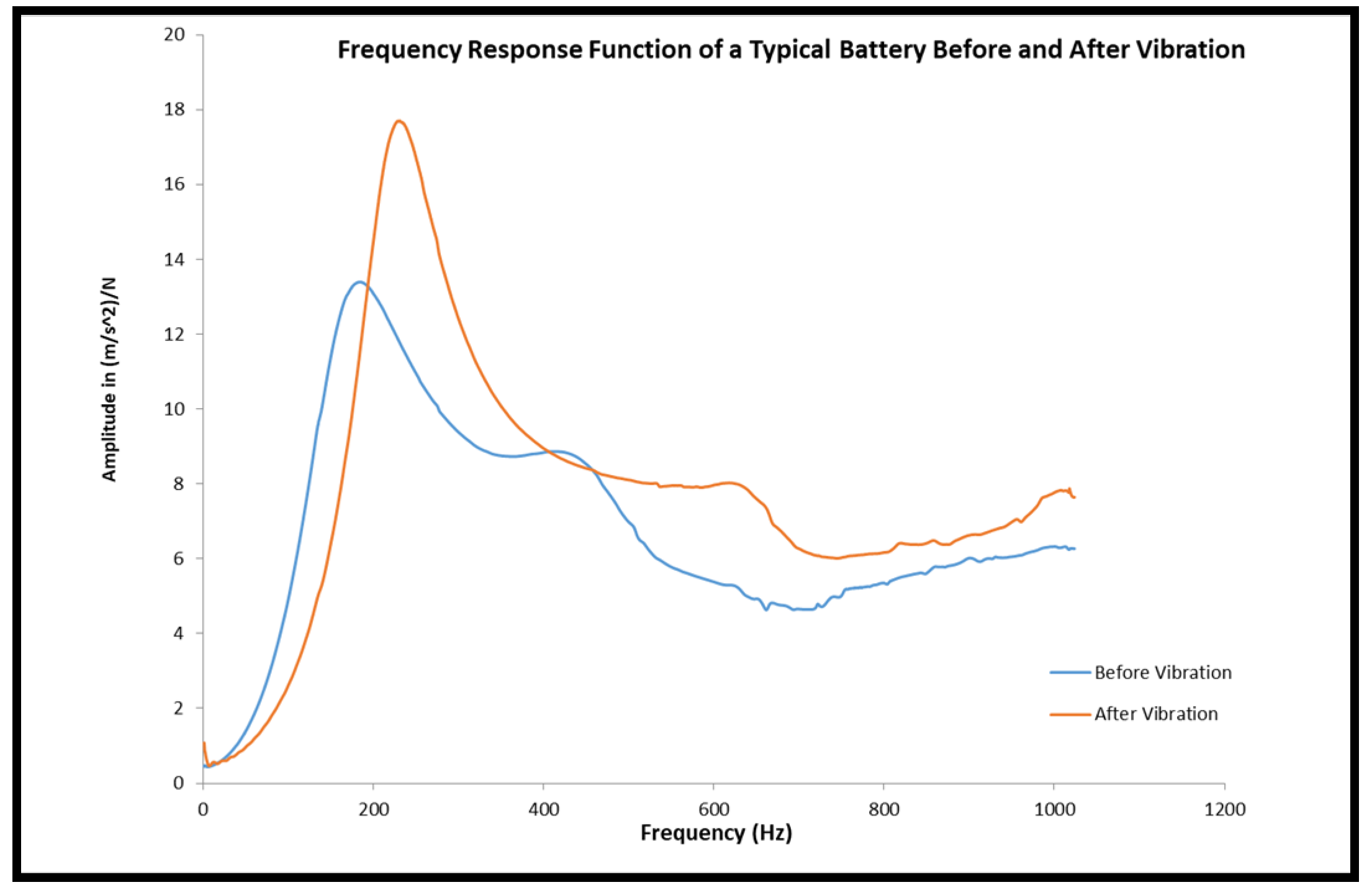
The effect of vibration on the internal components of the cell was one parameter studied as a part of the study. A FRF curve plot was drawn at two different states i.e., in the new cell and the post-vibration testing. The maximum amplitude, frequency at maximum amplitude i.e., first mode resonance frequency and the corresponding dynamic stiffness of the cell were measured and given in Table 2 for a cell without vibration and in Table 3 for a cell with vibration.
It was thus observed that the average max amplitude was 14.6 (m/s2)/N and the corresponding frequency and dynamic stiffness was 172.5 Hz and 81.63 N/mm, respectively. After the cell was tested for its vibration the average max amplitude increased to 16.7 (m/s2)/N i.e., 14% and the corresponding increase in the frequency and dynamic stiffness was 239.3 Hz and dynamic 138.83 N/mm i.e., 38% and 70%, respectively. This increment in the dynamic stiffness could be attributed to the distributed mass of the cell components which had earlier acted as lumped mass before vibration. A typical FRF curve for one cell is given in Figure 14 wherein shift in frequency and amplitude was clearly observed.

4. Conclusions

The cells were subjected to sinusoidal vibration and nail penetration at two different SoC. The following inferences were drawn from the analysis:
  • Morphology analysis of vibration-tested anode showed the presence of a tower-like structure which had grown due to deposition of Fe and P elements from the cathode.
  • Compositional analysis showed that, when the LiB undergoes localized mechanical damage without a thermal runaway then that leads to uneven distribution of the elements within the electrode surface.
  • In the top side location away from centre, for the cathode at 50% SoC in nail-penetrated samples, the elemental Wt.% for C, O, P and Fe was similar before and after testing and thus there was no effect of abuse on the distribution of the elements.
  • Capacity fade happened in the cells that were in 100% SoC to 50% SoC as the voltage dropped by 0.3 to 0.4 V.
  • After the cell was tested for its sinusoidal vibration the average max amplitude, resonance frequency, dynamic stiffness and internal resistance increased by 14%, 38%, 70% and 25% respectively.
  • FRF analysis of LiB can inform us about the state of the cell and can be used as a non-destructive evaluation technique.
  • It is important to validate the performance of an LiB for its application and the vibrational load during the lifetime of cell should be carefully considered while designing the battery pack.

Author Contributions

Conceptualization, supervision, project administration and investigation, M.R.S. and U.S.K.; Methodology, validation, writing and investigation, A.B.K.P.

Funding

This research received no external funding.

Acknowledgments

The authors would like to thank the team from Automotive Electronics Laboratory, Automotive Materials Laboratory and NVH laboratory of ARAI for their kind support on the characterization of the cells.

Conflicts of Interest

The authors declare no conflict of interest. The funders had no role in the design of the study; in the collection, analyses, or interpretation of data; in the writing of the manuscript, or in the decision to publish the results.

References

  1. Kasnatscheew, J.; Evertz, M.; Kloepsch, R.; Streipert, B.; Wagner, R.; Cekic Laskovic, I.; Winter, M. Learning from Electrochemical Data: Simple Evaluation and Classification of LiMO2-type-based Positive Electrodes for Li-Ion Batteries. Energy Technol. 2017, 5, 1670–1679. [Google Scholar] [CrossRef]
  2. Kasnatscheew, J.; Evertz, M.; Streipert, B.; Wagner, R.; Nowak, S.; Laskovic, I.C.; Winter, M. Improving cycle life of layered lithium transition metal oxide (LiMO2) based positive electrodes for Li ion batteries by smart selection of the electrochemical charge conditions. J. Power Sources 2017, 359, 458–467. [Google Scholar] [CrossRef]
  3. Scrosati, B.; Garche, J. Lithium batteries: Status, prospects and future. J. Power Sources 2010, 195, 2419–2430. [Google Scholar] [CrossRef]
  4. Choi, N.S.; Chen, Z.; Freunberger, S.A.; Ji, X.; Sun, Y.K.; Amine, K.; Yushin, G.; Nazar, L.F.; Cho, J.; Bruce, P.G. Challenges facing lithium batteries and electrical double-layer capacitors. Angew. Chem. Int. Ed. 2012, 51, 9994–10024. [Google Scholar] [CrossRef] [PubMed]
  5. Owen, J.R. Rechargeable lithium batteries. Chem. Soc. Rev. 1997, 26, 259–267. [Google Scholar] [CrossRef]
  6. Roberts, M.; Johns, P.; Owen, J.; Brandell, D.; Edstrom, K.; El Enany, G.; Guery, C.; Golodnitsky, D.; Lacey, M.; Lecoeur, C.; et al. 3D lithium ion batteries—From fundamentals to fabrication. J. Mater. Chem. 2011, 21, 9876–9890. [Google Scholar] [CrossRef]
  7. Kasnatscheew, J.; Wagner, R.; Winter, M.; Cekic-Laskovic, I. Interfaces and Materials in Lithium Ion Batteries: Challenges for Theoretical Electrochemistry. In Modeling Electrochemical Energy Storage at the Atomic Scale; Springer: Cham, Germany, 2018; pp. 23–51. [Google Scholar]
  8. Janek, J.; Zeier, W.G. A solid future for battery development. Energy 2016, 500, 300. [Google Scholar] [CrossRef]
  9. Goodenough, J.B.; Kim, Y. Challenges for rechargeable batteries. J. Power Sources 2011, 196, 6688–6694. [Google Scholar] [CrossRef]
  10. Padhi, A.K.; Nanjundaswamy, K.S.; Goodenough, J.B. Phospho-olivines as positive-electrode materials for rechargeable lithium batteries. J. Electrochem. Soc. 1997, 144, 1188–1194. [Google Scholar] [CrossRef]
  11. Liu, H.; Cao, Q.; Fu, L.J.; Li, C.; Wu, Y.P.; Wu, H.Q. Doping effects of zinc on LiFePO4 cathode material for lithium ion batteries. Electrochem. Commun. 2006, 8, 1553–1557. [Google Scholar] [CrossRef]
  12. Chung, S.Y.; Bloking, J.T.; Chiang, Y.M. Electronically conductive phospho-olivines as lithium storage electrodes. Nat. Mater. 2002, 1, 123–128. [Google Scholar] [CrossRef] [PubMed]
  13. Ellis, B.L.; Lee, K.T.; Nazar, L.F. Positive electrode materials for Li-ion and Li-batteries. Chem. Mater. 2010, 22, 691–714. [Google Scholar] [CrossRef]
  14. Whittingham, M.S. Lithium batteries and cathode materials. Chem. Rev. 2004, 104, 4271–4302. [Google Scholar] [CrossRef] [PubMed]
  15. He, P.; Yu, H.; Zhou, H. Layered lithium transition metal oxide cathodes towards high energy lithium-ion batteries. J. Mater. Chem. 2012, 22, 3680–3695. [Google Scholar] [CrossRef]
  16. Lang, J.F.; Kjell, G. Comparing vibration measurements in an electric vehicle with standard vibration requirements for Li-ion batteries using power spectral density analysis. Int. J. Electr. Hybrid Veh. 2015, 7, 272–286. [Google Scholar] [CrossRef]
  17. Hooper, J.M.; Marco, J. Characterising the in-vehicle vibration inputs to the high voltage battery of an electric vehicle. J. Power Sources 2014, 245, 510–519. [Google Scholar] [CrossRef]
  18. Unkelhaeuser, T.; Smallwood, D. Electrochemical Storage System Abuse Test Procedure Manual; USABC/SNL CRADA No. SC961447; United States Advanced Battery Consortium (USABC): Washington, WA, USA, 1999. [Google Scholar]
  19. ECE R100.2. Uniform Provisions Concerning the Approval of Vehicles with Regard to Specific Requirements for the Electric Power Train; UN/ECE: Geneva, Switzerland, 2013. [Google Scholar]
  20. Automotive Industry Standard 048—Battery Operated Vehicles—Safety Requirements of Traction Batteries; Automotive Research Association of India (ARAI): Pune, India, 2009.
  21. Golla-Schindler, U.; Zeibig, D.; Prickler, L.; Behn, S.; Bernthaler, T.; Schneider, G. Characterization of degeneration phenomena in lithium-ion batteries by combined microscopic techniques. Micron 2018, 113, 10–19. [Google Scholar] [CrossRef]
  22. Liu, S.; Hong, X.; Wang, D.; Li, Y.; Xu, J.; Zheng, C.; Xie, K. Hollow carbon spheres with nanoporous shells and tailored chemical interfaces as sulfur host for long cycle life of lithium sulfur batteries. Electrochim. Acta 2018, 279, 10–18. [Google Scholar] [CrossRef]
  23. Babu, P.A.; Waghmare, A.S.; Mulla, S.M.; Karle, U.S.; Saraf, M.R. Material characterization of Lithium-ion battery cells by scanning electron microscopy & X-ray diffraction techniques. In Proceedings of the 2017 IEEE Transportation Electrification Conference (ITEC-India), Pune, India, 13–15 December 2017; pp. 1–5. [Google Scholar]
  24. Barsoukov, E.; Macdonald, J.R. Impedance Spectroscopy: Theory, Experiment, and Applications; John Wiley & Sons: Hoboken, NJ, USA, 2018. [Google Scholar]
  25. Huet, F. A review of impedance measurements for determination of the state-of-charge or state-of-health of secondary batteries. J. Power Sources 1998, 70, 59–69. [Google Scholar] [CrossRef]
  26. Buller, S. Impedance Based Simulation Models for Energy Storage Devices in Advanced Automotive Power Systems; Shaker Verlag: Herzogenrath, Germany, 2002. [Google Scholar]
  27. Orazem, M.E.; Tribollet, B. Electrochemical Impedance Spectroscopy; John Wiley & Sons: Hoboken, NJ, USA, 2011; Volume 48. [Google Scholar]
  28. Farhat, D.; Maibach, J.; Eriksson, H.; Edström, K.; Lemordant, D.; Ghamouss, F. Towards high-voltage Li-ion batteries: Reversible cycling of graphite anodes and Li-ion batteries in adiponitrile-based electrolytes. Electrochim. Acta 2018, 281, 299–311. [Google Scholar] [CrossRef]
  29. Illig, J.; Schmidt, J.P.; Weiss, M.; Weber, A.; Ivers-Tiffée, E. Understanding the impedance spectrum of 18650 LiFePO4-cells. J. Power Sources 2013, 239, 670–679. [Google Scholar] [CrossRef]
  30. Samad, N.A.; Kim, Y.; Siegel, J.B.; Stefanopoulou, A.G. Battery capacity fading estimation using a force-based incremental capacity analysis. J. Electrochem. Soc. 2016, 163, A1584–A1594. [Google Scholar] [CrossRef]
  31. Dai, H.; Yu, C.; Wei, X.; Sun, Z. State of charge estimation for lithium-ion pouch batteries based on stress measurement. Energy 2017, 129, 16–27. [Google Scholar] [CrossRef]
  32. Cannarella, J.; Arnold, C.B. State of health and charge measurements in lithium-ion batteries using mechanical stress. J. Power Sources 2014, 269, 7–14. [Google Scholar] [CrossRef]
  33. Hooper, J.M.; Marco, J. Experimental modal analysis of lithium-ion pouch cells. J. Power Sources 2015, 285, 247–259. [Google Scholar] [CrossRef] [Green Version]
  34. Pham, H.L.; Dietz, J.E.; Adams, D.E.; Sharp, N.D. Lithium-ion battery cell health monitoring using vibration diagnostic test. In Proceedings of the ASME 2013 International Mechanical Engineering Congress and Exposition, San Diego, CA, USA, 15–21 November 2013; American Society of Mechanical Engineers: New York, NY, USA, 2013; p. V04BT04A048. [Google Scholar]
Figure 1. Vibration test fixture and setup.
Wevj 10 00069 g001
Figure 2. Dynamic stiffness measurement set up.
Wevj 10 00069 g002
Figure 3. New cell anode.
Wevj 10 00069 g003
Figure 4. New cell cathode.
Wevj 10 00069 g004
Figure 5. Nail-penetrated cell anode with location away from centre (50% state of charge (SoC)).
Wevj 10 00069 g005
Figure 6. Nail-penetrated cell cathode with location away from centre (50% SoC).
Wevj 10 00069 g006
Figure 7. Nail-penetrated cell anode with location at centre (50% SoC).
Wevj 10 00069 g007
Figure 8. Nail-penetrated cell cathode with location at centre (50% SoC).
Wevj 10 00069 g008
Figure 9. Nail-penetrated cell anode with location at centre (100% SoC).
Wevj 10 00069 g009
Figure 10. Nail-penetrated cell cathode with location at centre (100% SoC).
Wevj 10 00069 g010
Figure 11. Anode of the cell after vibration testing.
Wevj 10 00069 g011
Figure 12. Cathode of the cell after vibration testing.
Wevj 10 00069 g012
Figure 13. Nyquist plot for new cell and cell tested after vibration testing.
Wevj 10 00069 g013
Figure 14. Typical FRF curve for cell before and after vibration.
Wevj 10 00069 g014
Table 1. Test profile for sinusoidal vibration.
Frequency Range (Hz)Peak Acceleration (g)Duration (min)
20–10372
20–40272
40–901.572
90–140172
140–1900.7572
Table 2. Frequency response function (FRF) analysis of new cell.
CurveMax Amplitude (m/s2)/NMax Amplitude’s Freq, (Hz)Dynamic Stiffness at Max Amplitude Freq (N/mm)
Cell 115.3156.5063.17
Cell 215.1177.2582.18
Cell 313.4183.7599.53
Average14.6172.5081.63
Table 3. FRF analysis of cell after vibration.
CurveMax Amplitude (m/s2)/NMax Amplitude’s Freq, (Hz)Dynamic Stiffness at Max Amplitude Freq (N/mm)
Cell 117.0216.5109.09
Cell 215.3270.5188.45
Cell 317.7231.0118.96
Average16.7239.3138.83